WO2025046856A1 - 磁気粒子イメージング装置用磁石 - Google Patents
磁気粒子イメージング装置用磁石 Download PDFInfo
- Publication number
- WO2025046856A1 WO2025046856A1 PCT/JP2023/031911 JP2023031911W WO2025046856A1 WO 2025046856 A1 WO2025046856 A1 WO 2025046856A1 JP 2023031911 W JP2023031911 W JP 2023031911W WO 2025046856 A1 WO2025046856 A1 WO 2025046856A1
- Authority
- WO
- WIPO (PCT)
- Prior art keywords
- pair
- coil
- coils
- magnet
- split
- Prior art date
- Legal status (The legal status is an assumption and is not a legal conclusion. Google has not performed a legal analysis and makes no representation as to the accuracy of the status listed.)
- Pending
Links
Images






Classifications
-
- A—HUMAN NECESSITIES
- A61—MEDICAL OR VETERINARY SCIENCE; HYGIENE
- A61B—DIAGNOSIS; SURGERY; IDENTIFICATION
- A61B5/00—Measuring for diagnostic purposes; Identification of persons
- A61B5/05—Detecting, measuring or recording for diagnosis by means of electric currents or magnetic fields; Measuring using microwaves or radio waves
- A61B5/0515—Magnetic particle imaging
Definitions
- This disclosure relates to magnets for magnetic particle imaging devices.
- Patent Document 1 JP 2022-126838 A (Patent Document 1) describes a magnet for a magnetic particle imaging (MPI: Magnet Particle Imaging) device.
- the magnet for the magnetic particle imaging device described in Patent Document 1 has a pair of DC coils and a pair of AC coils.
- a magnetic field is generated along the third direction at the position where the ends of the pair of DC coils in the third direction face each other. Due to the generation of such a magnetic field, the length of the zero magnetic field region in the third direction becomes smaller. In order to extend the length of the zero magnetic field region in the third direction, a circular correction coil is used in the magnet for magnetic particle imaging devices described in Patent Document 1.
- the present disclosure has been made in consideration of the problems of the conventional technology described above. More specifically, the present disclosure provides a magnet for a magnetic particle imaging device that can prevent the zero magnetic field region from becoming shorter when the zero magnetic field region is moved.
- the magnet for a magnetic particle imaging device of the present disclosure comprises a pair of first DC coils, a pair of second DC coils, and a pair of AC coils.
- the pair of first DC coils are arranged opposite each other in a first direction.
- the pair of second DC coils are arranged opposite each other in a second direction perpendicular to the first direction or in a third direction perpendicular to the first and second directions.
- the pair of AC coils are arranged opposite each other in the first direction or the second direction.
- Each of the pair of second DC coils has a pair of first straight portions. Each of the pair of first straight portions extends along the same direction as the direction in which the pair of AC coils are arranged opposite each other.
- the magnet for magnetic particle imaging devices disclosed herein can prevent the zero magnetic field region from becoming shorter when the zero magnetic field region is moved.
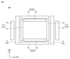
- FIG. 1 is a perspective view of a magnet 100 for a magnetic particle imaging device.
- 1 is a schematic first cross-sectional view of a magnet 100 for a magnetic particle imaging device.
- FIG. 2 is a schematic second cross-sectional view of the magnet 100 for a magnetic particle imaging device.
- FIG. 3 is a schematic third cross-sectional view of the magnet 100 for a magnetic particle imaging device.
- FIG. 2 is a perspective view of a magnet 200 for a magnetic particle imaging device.
- 1 is a schematic first cross-sectional view of a magnet 200 for a magnetic particle imaging device.
- FIG. 2 is a schematic second cross-sectional view of the magnet 200 for a magnetic particle imaging device.
- FIG. 3 is a schematic third cross-sectional view of the magnet 200 for a magnetic particle imaging device.
- FIG. 11 is a graph showing the relationship between the position in the first direction DR1 and the magnetic fields 14, 23, and 51.
- FIG. 3 is a perspective view of a magnet 300 for a magnetic particle imaging device.
- FIG. 4 is a side view of a magnet 400 for a magnetic particle imaging device.
- FIG. 4 is a plan view of a magnet 400 for a magnetic particle imaging device.
- Embodiment 1 A description will be given of a magnet for a magnetic particle imaging device according to embodiment 1.
- the magnet for a magnetic particle imaging device according to embodiment 1 is taken as a magnet 100 for a magnetic particle imaging device.
- FIG. 1 is a perspective view of a magnet 100 for a magnetic particle imaging device. As shown in FIG. 1, the magnet 100 for a magnetic particle imaging device has a pair of first DC coils 10, a pair of second DC coils 20, and a pair of AC coils 30.
- the pair of first DC coils 10 are arranged facing each other with a gap in between in the first direction DR1. That is, the first direction DR1 is the direction in which the pair of first DC coils 10 are arranged facing each other.
- the second direction DR2 is a direction perpendicular to the first direction DR1
- the third direction DR3 is a direction perpendicular to the first direction DR1 and the second direction DR2.
- the first DC coil 10 has a pair of straight portions 11 and a pair of straight portions 12.
- the pair of straight portions 11 are arranged facing each other with a gap in the second direction DR2.
- the straight portions 11 extend along the third direction DR3.
- One of the pair of straight portions 11 may be referred to as straight portion 11a, and the other of the pair of straight portions 11 may be referred to as straight portion 11b.
- the pair of straight portions 12 are arranged facing each other with a gap in the third direction DR3.
- the straight portions 12 extend along the second direction DR2.
- One of the pair of straight portions 12 may be referred to as straight portion 12a, and the other of the pair of straight portions 12 may be referred to as straight portion 12b.
- the straight line portions 11a and 11b of the first DC coil 10a are arranged opposite the straight line portions 11a and 11b of the first DC coil 10b with a gap therebetween.
- the straight line portions 12a and 12b of the first DC coil 10a are arranged opposite the straight line portions 12a and 12b of the first DC coil 10b with a gap therebetween.
- the direction of the current flowing through the first DC coil 10a is opposite to the direction of the current flowing through the first DC coil 10b.
- the direction of the current flowing through the straight portion 11a of the first DC coil 10a is opposite to the direction of the current flowing through the straight portion 11a of the first DC coil 10b
- the direction of the current flowing through the straight portion 11b of the first DC coil 10a is opposite to the direction of the current flowing through the straight portion 11b of the first DC coil 10b
- the direction of the current flowing through the straight portion 12a of the first DC coil 10a is opposite to the direction of the current flowing through the straight portion 12a of the first DC coil 10b
- the direction of the current flowing through the straight portion 12b of the first DC coil 10a is opposite to the direction of the current flowing through the straight portion 12b of the first DC coil 10b.
- the current flowing through the first DC coil 10 is supplied from a DC power source (not shown).
- FIG. 2 is a schematic first cross-sectional view of the magnet 100 for magnetic particle imaging device.
- the pair of second DC coils 20 and the pair of AC coils 30 are omitted, and the generated magnetic field is shown by a dotted line.
- FIG. 2 also shows a cross section perpendicular to the second direction DR2.
- a magnetic field as shown in FIG. 2 is generated due to the direction of the current as described above. More specifically, the pair of first DC coils 10 generates a zero magnetic field region 13 between the pair of first DC coils 10. In the zero magnetic field region 13, the component of the magnetic field along the third direction DR3 is zero. The zero magnetic field region 13 extends in the third direction DR3. When no current flows through the pair of AC coils 30, the zero magnetic field region 13 is at the midpoint MP of the pair of first DC coils 10 in the first direction DR1.
- the pair of first DC coils 10 generate a magnetic field 14 at a position where one end of the first DC coil 10a in the third direction DR3 faces one end of the first DC coil 10b in the third direction DR3, and at a position where the other end of the first DC coil 10a in the third direction DR3 faces the other end of the first DC coil 10b in the third direction DR3.
- the direction of the magnetic field 14 is along the third direction DR3.
- the first DC coil 10 has a first length and a second length.
- the first length is the length of the first DC coil 10 in the second direction DR2.
- the second length is the length of the first DC coil 10 in the third direction DR3. It is preferable that the second length is greater than the first length. In other words, it is preferable that the longitudinal direction of the first DC coil 10 is aligned with the third direction DR3. From another perspective, it is preferable that the length of the straight portion 11 is greater than the length of the straight portion 12.
- the pair of second DC coils 20 are arranged, for example, facing each other with a gap in between in the third direction DR3. Note that one of the pair of second DC coils 20 may be referred to as the second DC coil 20a, and the other of the pair of second DC coils 20 may be referred to as the second DC coil 20b.
- the second DC coil 20 has a pair of straight portions 21 and a pair of straight portions 22.
- the pair of straight portions 21 are arranged facing each other with a gap in the first direction DR1.
- the straight portions 21 extend along the second direction DR2.
- One of the pair of straight portions 21 may be referred to as straight portion 21a, and the other of the pair of straight portions 21 may be referred to as straight portion 21b.
- the pair of straight portions 22 are arranged facing each other with a gap in the second direction DR2.
- the straight portions 22 extend along the first direction DR1.
- One of the pair of straight portions 22 may be referred to as straight portion 22a, and the other of the pair of straight portions 22 may be referred to as straight portion 22b.
- the shape and ampere-turns of the second DC coil 20 are different from those of the first DC coil 10, for example. Note that an ampere-turn is the product of the coil current per turn and the number of turns.
- the straight line portions 21a and 21b of the second DC coil 20a are arranged opposite the straight line portions 21a and 21b of the second DC coil 20b with a gap therebetween.
- the straight line portions 22a and 22b of the second DC coil 20a are arranged opposite the straight line portions 22a and 22b of the second DC coil 20b with a gap therebetween. Note that the straight line portion 21a is closer to the first DC coil 10a than the straight line portion 21b in the first direction DR1.
- the direction of the current flowing through the second DC coil 20a is opposite to the direction of the current flowing through the second DC coil 20b.
- the direction of the current flowing through the straight portion 21a of the second DC coil 20a is opposite to the direction of the current flowing through the straight portion 21a of the second DC coil 20b
- the direction of the current flowing through the straight portion 21b of the second DC coil 20a is opposite to the direction of the current flowing through the straight portion 21b of the second DC coil 20b
- the direction of the current flowing through the straight portion 22a of the second DC coil 20a is opposite to the direction of the current flowing through the straight portion 12a of the second DC coil 20b
- the direction of the current flowing through the straight portion 22b of the second DC coil 20a is opposite to the direction of the current flowing through the straight portion 22b of the second DC coil 20b.
- the current flowing through the second DC coil 20 is supplied from a DC power source (not shown).
- the second DC coil 20 has a third length and a fourth length.
- the third length is the length of the second DC coil 20 in the first direction DR1.
- the fourth length is the length of the second DC coil 20 in the second direction DR2. It is preferable that the third length is greater than the fourth length. In other words, it is preferable that the longitudinal direction of the second DC coil 20 is aligned with the first direction DR1. From another perspective, it is preferable that the length of the straight portion 22 is greater than the length of the straight portion 21.
- FIG. 3 is a schematic second cross-sectional view of the magnet 100 for magnetic particle imaging device.
- the pair of first DC coils 10 and the pair of AC coils 30 are omitted, and the generated magnetic field is indicated by a dotted line.
- FIG. 3 also shows a cross section perpendicular to the first direction DR1.
- the pair of second DC coils 20 generate a magnetic field 23 at a position where one end of the first DC coil 10a in the third direction DR3 faces one end of the first DC coil 10b in the third direction DR3, and at a position where the other end of the first DC coil 10a in the third direction DR3 faces the other end of the first DC coil 10b in the third direction DR3.
- the direction of the magnetic field 23 is along the third direction DR3, and is opposite to the direction of the magnetic field 14.
- the direction of the current flowing through the straight portion 21a of the second DC coil 20a is opposite to the direction of the current flowing through the straight portion 12a of the first DC coil 10a
- the direction of the current flowing through the straight portion 21b of the second DC coil 20a is opposite to the direction of the current flowing through the straight portion 12a of the first DC coil 10b
- the direction of the current flowing through the straight portion 21a of the second DC coil 20b is opposite to the direction of the current flowing through the straight portion 12b of the first DC coil 10a
- the direction of the current flowing through the straight portion 21b of the second DC coil 20b is opposite to the direction of the current flowing through the straight portion 12b of the first DC coil 10b.
- the pair of AC coils 30 are arranged facing each other with a gap in between in the first direction DR1.
- One of the pair of AC coils 30 may be referred to as AC coil 30a, and the other of the pair of AC coils 30 may be referred to as AC coil 30b.
- the pair of AC coils 30 are arranged between the pair of first DC coils 10.
- the AC coil 30a is closer to the first DC coil 10a than the AC coil 30b.
- the AC coil 30 has a pair of straight portions 31 and a pair of straight portions 32.
- the pair of straight portions 31 are arranged facing each other with a gap in the second direction DR2.
- the straight portions 31 extend along the third direction DR3.
- One of the pair of straight portions 31 may be referred to as straight portion 31a, and the other of the pair of straight portions 31 may be referred to as straight portion 31b.
- the pair of straight portions 32 are arranged facing each other with a gap in the third direction DR3.
- the straight portions 32 extend along the second direction DR2.
- One of the pair of straight portions 32 may be referred to as straight portion 32a, and the other of the pair of straight portions 32 may be referred to as straight portion 32b.
- the straight line portions 31a and 31b of the AC coil 30a are arranged opposite the straight line portions 31a and 31b of the AC coil 30b with a gap therebetween.
- the straight line portions 32a and 32b of the AC coil 30a are arranged opposite the straight line portions 32a and 32b of the AC coil 30b with a gap therebetween.
- the direction of the current flowing through the AC coil 30a is the same as the direction of the current flowing through the AC coil 30b.
- the direction of the current flowing through the straight portion 31a of the AC coil 30a is the same as the direction of the current flowing through the straight portion 31a of the AC coil 30b
- the direction of the current flowing through the straight portion 31b of the AC coil 30a is the same as the direction of the current flowing through the straight portion 31b of the AC coil 30b
- the direction of the current flowing through the straight portion 32a of the AC coil 30a is the same as the direction of the current flowing through the straight portion 32a of the AC coil 30b
- the direction of the current flowing through the straight portion 32b of the AC coil 30a is the same as the direction of the current flowing through the straight portion 32b of the AC coil 30b.
- the current flowing through the AC coil 30 is supplied from an AC power source (not shown). When a current flows through the pair of AC coils 30, the zero magnetic field region 13 moves along the first direction DR1.
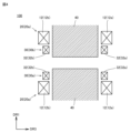
- FIG. 4 is a schematic third cross-sectional view of the magnet 100 for a magnetic particle imaging device.
- the pair of second DC coils 20 are omitted.
- FIG. 4 also shows a cross section perpendicular to the second direction DR2.
- the magnet 100 for a magnetic particle imaging device may further have an iron core 40.
- the pair of AC coils 30 may be arranged opposite to each other in the second direction DR2. In this case, when a current flows through the pair of AC coils 30, the zero magnetic field region 13 moves along the second direction DR2.
- the first DC coil 10 has both the pair of straight portions 11 and the pair of straight portions 12, but the first DC coil 10 does not have to have any straight portions. That is, the first DC coil 10 may be a circular coil. Furthermore, the first DC coil 10 may have only either the pair of straight portions 11 or the pair of straight portions 12.
- the effects of the magnet 100 for magnetic particle imaging devices will be described below in comparison with a magnet for magnetic particle imaging devices according to a comparative example.
- the magnet for magnetic particle imaging devices according to the comparative example will be referred to as a magnet 200 for magnetic particle imaging devices.
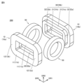
- Figure 5 is a perspective view of magnet 200 for a magnetic particle imaging device.
- magnet 200 for a magnetic particle imaging device has a pair of DC circular coils 50 instead of the pair of second DC coils 20.
- the pair of DC circular coils 50 are arranged facing each other with a gap in between in the second direction DR2, similar to the pair of second DC coils 20.
- the configuration of magnet 200 for a magnetic particle imaging device is the same as the configuration of magnet 100 for a magnetic particle imaging device.
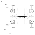
- FIG. 6 is a schematic first cross-sectional view of the magnet 200 for magnetic particle imaging device.
- the pair of first DC coils 10 and the pair of AC coils 30 are omitted, and the generated magnetic field is shown by a dotted line.
- FIG. 6 shows a cross section passing through the midpoint MP and perpendicular to the first direction DR1. As shown in FIG.
- the pair of DC circular coils 50 generate a magnetic field 51 at a position where one end of the first DC coil 10a in the third direction DR3 faces one end of the first DC coil 10b in the third direction DR3, and at a position where the other end of the first DC coil 10a in the third direction DR3 faces the other end of the first DC coil 10b in the third direction DR3.
- the direction of the magnetic field 51 is along the third direction DR3, which is opposite to the direction of the magnetic field 14.
- Figure 7 is a schematic second cross-sectional view of magnet 200 for magnetic particle imaging device.
- the pair of AC coils 30 and the pair of DC circular coils 50 are omitted, and the generated magnetic field is shown by dotted lines.
- Figure 7 also shows a cross section perpendicular to second direction DR2.
- magnetic field 51 cancels out magnetic field 14, so that zero magnetic field region 13 is extended along third direction DR3 (see dotted line).
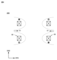
- FIG. 8 is a schematic third cross-sectional view of the magnet 200 for a magnetic particle imaging device.
- the pair of first DC coils 10 and the pair of AC coils 30 are omitted, and the generated magnetic field is shown by a dotted line.
- FIG. 8 also shows a cross section passing through a position shifted from the midpoint MP and perpendicular to the first direction DR1. As shown in FIG. 8, due to the circular shape of the DC circular coil 50, the magnetic field 51 fluctuates along the first direction DR1.
- the magnetic field 14 cannot be sufficiently canceled by the magnetic field 51, and the length of the zero magnetic field region 13 in the third direction DR3 becomes shorter.
- the second DC coil 20 has a pair of straight portions 22.
- the pair of straight portions 22 extend along the first direction DR1, i.e., the direction in which the pair of AC coils 30 move the zero magnetic field region 13 (the direction in which the pair of AC coils 30 face each other). Therefore, in the second DC coil 20, the fluctuation of the magnetic field 23 along the first direction DR1 is smaller than the fluctuation of the magnetic field 51 along the first direction DR1.
- a pair of second DC coils 20 are arranged facing each other with a gap in the second direction DR2.
- each of the pair of straight portions 21 extends along the third direction DR3.
- the configuration of the magnet 300 for magnetic particle imaging devices is different from the configuration of the magnet 100 for magnetic particle imaging devices. Note that in the magnet 100 for magnetic particle imaging devices, the second DC coil 20 does not generate a gradient magnetic field, but in the magnet 300 for magnetic particle imaging devices, the second DC coil 20 generates a gradient magnetic field.
- the magnitude of the gradient magnetic field generated by the first DC coil 10 is G
- the gradient magnetic field per unit current generated by the first DC coil 10 is C1
- the gradient magnetic field per unit current generated by the second DC coil 20 is C2
- the current flowing through the first DC coil 10 is I1
- the current flowing through the second DC coil 20 is I2
- the magnetic field 14 per unit current is Bz1
- the magnetic field 23 per unit current is Bz2 .
- C1 ⁇ I1 + C2 ⁇ I2 G (Equation 1)
- Bz1 ⁇ I1 + Bz2 ⁇ I2 0 (Equation 2).
- the pair of second DC coils 20 also generate a magnetic field 23 that cancels out the magnetic field 14, and the variation of the magnetic field 23 along the first direction DR1 is small, so that even when the pair of AC coils 30 move the zero magnetic field region 13 along the first direction DR1, the length of the zero magnetic field region 13 in the third direction DR3 can be maintained.
- each of the first split DC coil 24 and the second split DC coil 25, like the second DC coil 20, has a pair of straight portions arranged opposite each other with a gap in the first direction DR1 and extending along the third direction DR3, and a pair of other straight portions arranged opposite each other with a gap in the third direction DR3 and extending along the first direction DR1.
- Each of the first split AC coil 33 and the second split AC coil 34, like the AC coil 30, has a pair of straight portions arranged opposite each other with a gap in the second direction DR2 and extending along the third direction DR3, and a pair of other straight portions arranged opposite each other with a gap in the third direction DR3 and extending along the second direction DR2.
- Each of the pair of first DC coils has a pair of second straight portions, Each of the pair of second linear portions extends along the third direction, 2.
- Each of the pair of second DC coils includes at least a first split DC coil and a second split DC coil, the second split DC coil of one of the pair of second DC coils and the second split DC coil of the other of the pair of second DC coils are disposed opposite to each other with the first split DC coil of one of the pair of second DC coils and the first split DC coil of the other of the pair of second DC coils interposed therebetween, 9.
Landscapes
- Health & Medical Sciences (AREA)
- Life Sciences & Earth Sciences (AREA)
- Nuclear Medicine, Radiotherapy & Molecular Imaging (AREA)
- Biomedical Technology (AREA)
- Medical Informatics (AREA)
- Biophysics (AREA)
- Pathology (AREA)
- Engineering & Computer Science (AREA)
- Radiology & Medical Imaging (AREA)
- Heart & Thoracic Surgery (AREA)
- Physics & Mathematics (AREA)
- Molecular Biology (AREA)
- Surgery (AREA)
- Animal Behavior & Ethology (AREA)
- General Health & Medical Sciences (AREA)
- Public Health (AREA)
- Veterinary Medicine (AREA)
- Magnetic Resonance Imaging Apparatus (AREA)
- Measurement And Recording Of Electrical Phenomena And Electrical Characteristics Of The Living Body (AREA)
Priority Applications (3)
| Application Number | Priority Date | Filing Date | Title |
|---|---|---|---|
| CN202380101523.2A CN121729175A (zh) | 2023-08-31 | 2023-08-31 | 磁粒子成像装置用磁铁 |
| PCT/JP2023/031911 WO2025046856A1 (ja) | 2023-08-31 | 2023-08-31 | 磁気粒子イメージング装置用磁石 |
| JP2024501607A JP7573782B1 (ja) | 2023-08-31 | 2023-08-31 | 磁気粒子イメージング装置用磁石 |
Applications Claiming Priority (1)
| Application Number | Priority Date | Filing Date | Title |
|---|---|---|---|
| PCT/JP2023/031911 WO2025046856A1 (ja) | 2023-08-31 | 2023-08-31 | 磁気粒子イメージング装置用磁石 |
Publications (1)
| Publication Number | Publication Date |
|---|---|
| WO2025046856A1 true WO2025046856A1 (ja) | 2025-03-06 |
Family
ID=93154629
Family Applications (1)
| Application Number | Title | Priority Date | Filing Date |
|---|---|---|---|
| PCT/JP2023/031911 Pending WO2025046856A1 (ja) | 2023-08-31 | 2023-08-31 | 磁気粒子イメージング装置用磁石 |
Country Status (3)
| Country | Link |
|---|---|
| JP (1) | JP7573782B1 (https=) |
| CN (1) | CN121729175A (https=) |
| WO (1) | WO2025046856A1 (https=) |
Citations (6)
| Publication number | Priority date | Publication date | Assignee | Title |
|---|---|---|---|---|
| US20110089942A1 (en) * | 2008-06-23 | 2011-04-21 | Goodwill Patrick W | Improved techniques for magnetic particle imaging |
| JP2013518657A (ja) * | 2010-02-08 | 2013-05-23 | コーニンクレッカ フィリップス エレクトロニクス エヌ ヴィ | 片面送信コイルセットのアレイを持つ視野内の磁性粒子に作用する及び/又は検出するための装置及び方法 |
| US20150276902A1 (en) * | 2012-11-01 | 2015-10-01 | The Trustees Of Dartmouth College | System And Apparatus For Combined Magnetic Resonance Imaging With Magnetic Spectroscopy of Brownian Motion And/Or Magnetic Nanoparticle Imaging |
| JP2019523115A (ja) * | 2016-07-12 | 2019-08-22 | マグネティック・インサイト・インコーポレイテッドMagnetic Insight, Inc. | 磁気粒子イメージング |
| CN112155544A (zh) * | 2020-09-21 | 2021-01-01 | 东北大学 | 基于零磁场线的成像方法及装置、电子设备和存储介质 |
| WO2022220113A1 (ja) * | 2021-04-13 | 2022-10-20 | 三菱電機株式会社 | 磁気微粒子イメージング装置 |
-
2023
- 2023-08-31 WO PCT/JP2023/031911 patent/WO2025046856A1/ja active Pending
- 2023-08-31 CN CN202380101523.2A patent/CN121729175A/zh active Pending
- 2023-08-31 JP JP2024501607A patent/JP7573782B1/ja active Active
Patent Citations (6)
| Publication number | Priority date | Publication date | Assignee | Title |
|---|---|---|---|---|
| US20110089942A1 (en) * | 2008-06-23 | 2011-04-21 | Goodwill Patrick W | Improved techniques for magnetic particle imaging |
| JP2013518657A (ja) * | 2010-02-08 | 2013-05-23 | コーニンクレッカ フィリップス エレクトロニクス エヌ ヴィ | 片面送信コイルセットのアレイを持つ視野内の磁性粒子に作用する及び/又は検出するための装置及び方法 |
| US20150276902A1 (en) * | 2012-11-01 | 2015-10-01 | The Trustees Of Dartmouth College | System And Apparatus For Combined Magnetic Resonance Imaging With Magnetic Spectroscopy of Brownian Motion And/Or Magnetic Nanoparticle Imaging |
| JP2019523115A (ja) * | 2016-07-12 | 2019-08-22 | マグネティック・インサイト・インコーポレイテッドMagnetic Insight, Inc. | 磁気粒子イメージング |
| CN112155544A (zh) * | 2020-09-21 | 2021-01-01 | 东北大学 | 基于零磁场线的成像方法及装置、电子设备和存储介质 |
| WO2022220113A1 (ja) * | 2021-04-13 | 2022-10-20 | 三菱電機株式会社 | 磁気微粒子イメージング装置 |
Also Published As
| Publication number | Publication date |
|---|---|
| CN121729175A (zh) | 2026-03-24 |
| JPWO2025046856A1 (https=) | 2025-03-06 |
| JP7573782B1 (ja) | 2024-10-25 |
Similar Documents
| Publication | Publication Date | Title |
|---|---|---|
| US10291085B2 (en) | Magnetic assembly for an electric motor | |
| JP6397349B2 (ja) | 三相五脚型鉄心および静止電磁機器 | |
| TWI670745B (zh) | 緊湊型致偏磁體 | |
| US20080303620A1 (en) | DC Inductor | |
| JP7573782B1 (ja) | 磁気粒子イメージング装置用磁石 | |
| US6548919B2 (en) | Linear motor | |
| US5557205A (en) | Magnetic field generating apparatus for use in MRI | |
| CN116733846A (zh) | 一种悬浮力对称六极恒流源励磁电磁轴承及其设计方法 | |
| EP0764853B1 (en) | Magnet assembly in MRI instrument | |
| JP6926787B2 (ja) | 鉄心構造体、トランス、及び鉄損抑制方法 | |
| JP2011188546A (ja) | ボイスコイルモータ | |
| JP2016178828A (ja) | 電動機の回転子 | |
| US20200018804A1 (en) | Electric current sensor | |
| JP2018153030A (ja) | リニアモータ | |
| JP2865951B2 (ja) | 電磁石装置 | |
| JPWO2025046856A5 (https=) | ||
| JP5630861B2 (ja) | 外乱磁場計測センサ及びアクティブ型磁気シールドシステム | |
| JP3824032B2 (ja) | ボイスコイルモータ | |
| JP2005317623A (ja) | 直流リアクトル | |
| GB2533334A (en) | Improved magnet | |
| JP2017090126A (ja) | 電流センサ | |
| JP4215227B2 (ja) | 電磁石 | |
| JP2980226B2 (ja) | 荷電粒子蓄積リング用の電磁石 | |
| JP3868103B2 (ja) | 荷電粒子ビーム軌道の形成装置及びその運転方法 | |
| JP5587150B2 (ja) | 磁場制御装置 |
Legal Events
| Date | Code | Title | Description |
|---|---|---|---|
| ENP | Entry into the national phase |
Ref document number: 2024501607 Country of ref document: JP Kind code of ref document: A |
|
| WWE | Wipo information: entry into national phase |
Ref document number: 2024501607 Country of ref document: JP |
|
| 121 | Ep: the epo has been informed by wipo that ep was designated in this application |
Ref document number: 23950799 Country of ref document: EP Kind code of ref document: A1 |