WO2025046764A1 - 蓄熱タンク及び蓄熱空調給湯システム - Google Patents
蓄熱タンク及び蓄熱空調給湯システム Download PDFInfo
- Publication number
- WO2025046764A1 WO2025046764A1 PCT/JP2023/031356 JP2023031356W WO2025046764A1 WO 2025046764 A1 WO2025046764 A1 WO 2025046764A1 JP 2023031356 W JP2023031356 W JP 2023031356W WO 2025046764 A1 WO2025046764 A1 WO 2025046764A1
- Authority
- WO
- WIPO (PCT)
- Prior art keywords
- heat
- heat medium
- temperature
- medium
- heat storage
- Prior art date
- Legal status (The legal status is an assumption and is not a legal conclusion. Google has not performed a legal analysis and makes no representation as to the accuracy of the status listed.)
- Pending
Links
Images






Classifications
-
- F—MECHANICAL ENGINEERING; LIGHTING; HEATING; WEAPONS; BLASTING
- F24—HEATING; RANGES; VENTILATING
- F24F—AIR-CONDITIONING; AIR-HUMIDIFICATION; VENTILATION; USE OF AIR CURRENTS FOR SCREENING
- F24F5/00—Air-conditioning systems or apparatus not covered by F24F1/00 or F24F3/00, e.g. using solar heat or combined with household units such as an oven or water heater
-
- F—MECHANICAL ENGINEERING; LIGHTING; HEATING; WEAPONS; BLASTING
- F24—HEATING; RANGES; VENTILATING
- F24H—FLUID HEATERS, e.g. WATER OR AIR HEATERS, HAVING HEAT-GENERATING MEANS, e.g. HEAT PUMPS, IN GENERAL
- F24H7/00—Storage heaters, i.e. heaters in which the energy is stored as heat in masses for subsequent release
- F24H7/02—Storage heaters, i.e. heaters in which the energy is stored as heat in masses for subsequent release the released heat being conveyed to a transfer fluid
-
- F—MECHANICAL ENGINEERING; LIGHTING; HEATING; WEAPONS; BLASTING
- F28—HEAT EXCHANGE IN GENERAL
- F28D—HEAT-EXCHANGE APPARATUS, NOT PROVIDED FOR IN ANOTHER SUBCLASS, IN WHICH THE HEAT-EXCHANGE MEDIA DO NOT COME INTO DIRECT CONTACT
- F28D20/00—Heat storage plants or apparatus in general; Regenerative heat-exchange apparatus not covered by groups F28D17/00 or F28D19/00
Definitions
- This disclosure relates to a heat storage tank and a heat storage air conditioning and hot water supply system in the fields of air conditioning devices and hot water supply equipment.
- Patent Document 1 Conventionally, some heat storage air conditioning and hot water systems are equipped with a heat pump refrigeration cycle, a hot water tank, and a cold water tank (see, for example, Patent Document 1).
- the heat storage air conditioning and hot water system of Patent Document 1 stores hot exhaust heat during cooling operation and uses it for hot water supply, or stores cold exhaust heat during hot water heating and uses it for cooling operation, thereby utilizing heat that would have been wasted in conventional air conditioners and reducing power consumption.
- Patent Document 1 The heat storage air conditioning and hot water supply system of Patent Document 1 requires two pipes each for the heat medium to go and return between the cold water tank and the hot water tank and the heat source, i.e., a total of four pipes. This large number of pipes and the many construction steps required for installation make it difficult to install.
- the present disclosure aims to solve the problems described above, and to provide a heat storage tank and a heat storage air conditioning and hot water supply system that reduce the number of pipes in the heat storage air conditioning and hot water supply system and make installation easier.
- the heat storage tank includes a heat medium tank for storing a heat medium, and piping through which the heat medium flows, the high-temperature piping connected to the top of the heat medium tank, the low-temperature piping connected to the bottom of the heat medium tank, and a medium-temperature piping connected to the heat medium tank between the high-temperature piping and the low-temperature piping in the vertical direction of the heat medium tank, a first heat medium pump connected to the high-temperature piping and for causing the heat medium to flow into the heat medium tank and for causing the heat medium to flow out of the heat medium tank, and a second heat medium pump connected to the low-temperature piping and for causing the heat medium to flow into the heat medium tank and for causing the heat medium to flow out of the heat medium tank.
- the system includes a body pump, a first pipe connecting a high-temperature pipe and a medium-temperature pipe, a second pipe connecting the first pipe and a low-temperature pipe, a first flow path switching valve connected to the first pipe and the second pipe and switching the flow path through which the heat medium flows, and a second flow path switching valve connected to the second pipe and the low-temperature pipe and switching the flow path through which the heat medium flows.
- the first flow path switching valve and the second flow path switching valve are used to switch the flow path of the heat medium flowing inside the high-temperature pipe, the medium-temperature pipe, and the low-temperature pipe, thereby switching between low-temperature heat storage operation, high-temperature heat storage operation, heat dissipation operation, and simultaneous operation of each.
- the heat storage air conditioning and hot water supply system includes a heat storage tank of the above configuration, a plurality of indoor units having a user-side heat exchanger that exchanges heat between air and a heat medium, a heat medium circulation circuit including at least one of the plurality of indoor units and a heat storage tank, a heating inter-heat medium heat exchanger that heats the heat medium by exchanging heat between the heat source fluid of the heat source unit and the heat medium circulating in the heat medium circulation circuit, a cooling inter-heat medium heat exchanger that cools the heat medium by exchanging heat between the heat source fluid of the heat source unit and the heat medium circulating in the heat medium circulation circuit, a first heat medium circulation pump provided in the heat medium circulation circuit corresponding to the heating inter-heat medium heat exchanger, a second heat medium circulation pump provided in the heat medium circulation circuit corresponding to the cooling inter-heat medium heat exchanger, and a heat medium circulation pump that connects the indoor units and the heat storage tank to the heating inter-heat medium heat exchanger and the cooling inter
- a heat medium circulation circuit that connects the indoor unit and the heat storage tank to the heating inter-heat medium heat exchanger and the cooling inter-heat medium heat exchanger includes a plurality of heat medium flow control devices that control the flow rate of the heat medium
- a heat medium circulation circuit that connects the indoor unit and the heat storage tank to the heating inter-heat medium heat exchanger and the cooling inter-heat medium heat exchanger includes a plurality of heat medium temperature detection sensors that detect the temperature of the heat medium, and based on the detection information of the plurality of heat medium temperature detection sensors, the heat medium circulation circuit selects cooling, heating, cold heat storage, hot heat storage, hot water supply, and a combination of these operations by controlling the plurality of heat medium flow control valves and the plurality of heat medium flow control devices.
- the heat storage tank and heat storage air conditioning hot water supply system use a first flow path switching valve and a second flow path switching valve to switch the flow path of the heat medium flowing inside the high temperature pipe, the medium temperature pipe, and the low temperature pipe, thereby switching between low temperature heat storage operation, high temperature heat storage operation, heat release operation, and simultaneous operation of each.
- the heat storage tank and heat storage air conditioning hot water supply system require two pipes each for the forward and return of the heat medium for low temperature and high temperature heat storage and release, i.e., a total of four pipes.
- the heat storage tank and heat storage air conditioning hot water supply system uses a high temperature pipe, a medium temperature pipe, and a low temperature pipe, and can integrate the flow path of the medium temperature heat medium after heat storage and release into one, thereby reducing the number of pipes.
- the heat storage tank, the heat source unit, and the heat medium converter are often installed separately from each other, and reducing the number of connecting pipes simplifies the construction when installing the heat storage tank and the heat storage air conditioning hot water supply system, making installation easier.
- FIG. 4 is a circuit diagram showing a flow direction of a circulating medium during cold heat storage in the heat storage tank according to the first embodiment.
- FIG. 4 is a circuit diagram showing a flow direction of a circulating medium during hot heat storage in the heat storage tank according to the first embodiment.
- FIG. 4 is a circuit diagram showing a flow direction of a circulating medium during hot heat storage in the heat storage tank according to the first embodiment.
- FIG. 4 is a circuit diagram showing a flow direction of a circulating medium when simultaneously storing hot and cold heat in the heat storage tank according to the first embodiment.
- FIG. 4 is a circuit diagram showing a flow direction of a circulating medium during hot water supply operation of the heat storage tank according to the first embodiment.
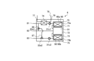
- FIG. FIG. 11 is a schematic diagram showing a heat storage tank according to a second embodiment.
- FIG. 11 is a circuit diagram showing a flow direction of a circulating medium during cold heat storage in a heat storage tank according to a second embodiment.
- FIG. 11 is a circuit diagram showing a flow direction of a circulating medium during hot heat storage in a heat storage tank according to a second embodiment.
- FIG. 11 is a circuit diagram showing a flow direction of a circulating medium during hot heat storage in a heat storage tank according to a second embodiment.
- FIG. 11 is a circuit diagram showing a flow direction of a circulating medium during hot heat storage in a heat storage tank according to a second embodiment.
- FIG. 11 is a circuit diagram showing the flow direction of a circulating medium when simultaneously storing hot and cold heat in a heat storage tank according to a second embodiment.
- FIG. 11 is a circuit diagram showing a flow direction of a circulating medium during hot water supply operation of a heat storage tank according to a second embodiment.
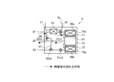
- FIG. 11 is a schematic diagram showing a heat storage tank according to a third embodiment.
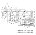
- FIG. 13 is a schematic diagram of a first example of a heat storage air conditioning and hot water supply system according to embodiment 4.
- FIG. 13 is a schematic diagram of a second example of a heat storage air conditioning and hot water supply system according to embodiment 4.
- 13 is a circuit diagram showing the flow direction of a circulating medium during heat storage utilization cooling and heating operation of a heat storage air conditioning hot water supply system according to embodiment 4.
- FIG. 13 is a circuit diagram showing the flow direction of the circulating medium during simultaneous hot and cold heat storage operation of the heat-storage air-conditioning and hot water supply system according to embodiment 4.
- FIG. 1 is a schematic diagram showing a heat storage tank 6 according to the first embodiment.
- the heat storage tank 6 is a tank for storing heat generated by a heat source unit.
- the heat storage tank 6 is used in a heat storage air conditioning hot water supply system 200 described later as an example (see FIG. 14).
- the heat storage tank 6 includes a heat medium tank 72, a high temperature pipe 81, a low temperature pipe 83, a medium temperature pipe 82, a hot water supply heat exchanger 74, a first heat medium pump 31c1, a second heat medium pump 31c2, a first pipe 86, and a second pipe 87.
- the heat storage tank 6 also includes a first flow path switching valve 32a1 and a second flow path switching valve 32a2. The configurations of the heat storage tank 6 described above will be described below.
- the heat storage tank 6 includes a heat medium tank 72 that stores a heat medium 91.
- the heat medium tank 72 stores the heat medium 91 that stores and releases heat.
- the heat medium 91 can be water, antifreeze, or an ethylene glycol aqueous solution.
- the upper part 72a of the heat medium tank 72 is a high-temperature heat medium part, where the high-temperature heat medium 91 is stored.
- the central part 72b of the heat medium tank 72 is a medium-temperature heat medium part, where the medium-temperature heat medium 91 is stored.
- the lower part 72c of the heat medium tank 72 is a low-temperature heat medium part, where the low-temperature heat medium 91 is stored.
- the heat storage tank 6 includes a high-temperature pipe 81 connected to the upper portion 72a of the heat medium tank 72, and a low-temperature pipe 83 connected to the lower portion 72c of the heat medium tank 72.
- the heat storage tank 6 also includes a medium-temperature pipe 82, through which the heat medium 91 flows, connected to the heat medium tank 72 between the high-temperature pipe 81 and the low-temperature pipe 83 in the vertical direction of the heat medium tank 72.
- the high-temperature pipe 81, the medium-temperature pipe 82, and the low-temperature pipe 83 are pipes through which the heat medium 91 flows.
- the high-temperature pipe 81, the medium-temperature pipe 82, and the low-temperature pipe 83 are connected to the heat medium tank 72 at three different heights.
- the high-temperature pipe 81 is connected to the upper part 72a of the heat medium tank 72
- the medium-temperature pipe 82 is connected to the central part 72b of the heat medium tank 72
- the low-temperature pipe 83 is connected to the lower part 72c of the heat medium tank 72.
- the high-temperature pipe 81 is connected to the upper part 72a of the heat medium tank 72, and the other end is connected to the pipe of the heat medium converter 3 described later (see FIG. 14).
- the hot water heat exchanger 74 and the first heat medium pump 31c1 are connected to the high-temperature pipe 81 midway through the pipe.
- the high-temperature pipe 81 is branched midway through the first pipe 86 described later, and is connected to the medium-temperature pipe 82 via the first pipe 86 and the first flow path switching valve 32a1 described later.
- the high-temperature pipe 81 is connected to the low-temperature pipe 83 via the first pipe 86, the first flow path switching valve 32a1, the second pipe 87, and the second flow path switching valve 32a2 described later.
- the medium temperature pipe 82 is connected to the center 72b of the heat medium tank 72, and the other end is connected to the pipe of the heat medium converter 3 (see FIG. 14).
- the medium temperature pipe 82 is branched midway through the pipeline by a first pipe 86 (described later), and is connected to the high temperature pipe 81 via the first pipe 86 and a first flow path switching valve 32a1 (described later).
- the low-temperature pipe 83 is connected to the lower part 72c of the heat medium tank 72, and the other end is connected to the pipe of the heat medium converter 3 described later (see FIG. 14).
- the low-temperature pipe 83 is also connected to the second flow path switching valve 32a2 and the second heat medium pump 31c2 midway through the pipeline.
- the low-temperature pipe 83 is connected to the high-temperature pipe 81 via the first pipe 86, the first flow path switching valve 32a1, the second pipe 87, and the second flow path switching valve 32a2 described later.
- the heat storage tank 6 is connected to the high-temperature pipe 81 and the water pipe 78 through which water flows, and is equipped with a hot water heat exchanger 74 that exchanges heat between the heat medium 91 flowing through the high-temperature pipe 81 and the water flowing through the water pipe 78.
- the hot water heat exchanger 74 is connected to the high-temperature pipe 81. In other words, the hot water heat exchanger 74 is provided on the high-temperature pipe 81.
- the hot water heat exchanger 74 is also connected to the water pipe 78.
- the hot water heat exchanger 74 exchanges heat between the water flowing through the water pipe 78 that flows in from the water supply port 76 and the heat medium 91 that flows in from the high-temperature pipe 81, and heats the water to a hot water supply temperature, and then flows out from the hot water supply port 77 and supplies hot water through the water pipe 78.
- the water is, for example, city water.
- the hot water supply temperature is a temperature suitable for use by the user, for example, 40°C.
- the heat storage tank 6 is equipped with a first heat medium pump 31c1 that causes the heat medium 91 to flow into the heat medium tank 72 and causes the heat medium 91 to flow out from the heat medium tank 72.
- the first heat medium pump 31c1 is connected to the high-temperature pipe 81. In other words, the first heat medium pump 31c1 is provided in the high-temperature pipe 81.
- the first heat medium pump 31c1 circulates the heat medium 91 stored inside the heat medium tank 72 within a circuit through which the heat medium 91 flows.
- the heat storage tank 6 is equipped with a second heat medium pump 31c2 that causes the heat medium 91 to flow into the heat medium tank 72 and causes the heat medium 91 to flow out from the heat medium tank 72.
- the second heat medium pump 31c2 is connected to the low-temperature piping 83. In other words, the second heat medium pump 31c2 is provided in the low-temperature piping 83.
- the second heat medium pump 31c2 circulates the heat medium 91 stored inside the heat medium tank 72 within the circuit through which the heat medium 91 flows.
- the first heat medium pump 31c1 and the second heat medium pump 31c2 are devices that are driven by, for example, a motor (not shown) and send the heat medium 91 by the action of pressure.
- the heat medium 91 is circulated in the piping by the first heat medium pump 31c1 and the second heat medium pump 31c2.
- the heat storage tank 6 only needs to have at least the first heat medium pump 31c1, and may not need to have the second heat medium pump 31c2.
- the heat medium 91 is circulated in the piping by the first heat medium pump 31c1, the first heat medium circulation pump 31a described later, or the second heat medium circulation pump 31b described later (see FIG. 14).
- the heat storage tank 6 includes a first pipe 86 that connects the high-temperature pipe 81 and the medium-temperature pipe 82 at a position on the high-temperature pipe 81 opposite the hot water supply heat exchanger 74 from the side where the heat medium tank 72 is located.
- One end of the first pipe 86 is connected to the high-temperature pipe 81, and the other end is connected to the medium-temperature pipe 82.
- the first pipe 86 also has a first flow path switching valve 32a1 connected midway through the pipeline.
- the heat storage tank 6 includes a second pipe 87 that connects the first pipe 86 and the low-temperature pipe 83.
- One end of the second pipe 87 is connected to the first pipe 86 via the first flow path switching valve 32a1, and the other end is connected to the low-temperature pipe 83 via the second flow path switching valve 32a2.
- the heat storage tank 6 is connected to the first pipe 86 and the second pipe 87, and is equipped with a first flow path switching valve 32a1 that switches the flow path through which the heat medium 91 flows.
- the heat storage tank 6 is also connected to the second pipe 87 and the low-temperature pipe 83, and is equipped with a second flow path switching valve 32a2 that switches the flow path through which the heat medium 91 flows.
- the first flow path switching valve 32a1 and the second flow path switching valve 32a2 switch the flow direction of the heat medium 91 in the circuit through which the heat medium 91 flows.
- the first flow path switching valve 32a1 and the second flow path switching valve 32a2 are, for example, three-way valves.
- the flow direction of the heat medium 91 is controlled by the first flow path switching valve 32a1 and the second flow path switching valve 32a2.
- the first flow path switching valve 32a1 and the second flow path switching valve 32a2 for example, switch between a circuit in which the heat medium 91 circulates between the upper portion 72a and the central portion 72b of the heat medium tank 72, and a circuit in which the heat medium 91 circulates between the upper portion 72a and the lower portion 72c.
- the heat storage tank 6 switches the flow path of the heat medium 91 flowing inside the high temperature pipe 81, the medium temperature pipe 82, and the low temperature pipe 83 using the first flow path switching valve 32a1 and the second flow path switching valve 32a2.
- the heat storage tank 6 switches between low temperature heat storage operation, high temperature heat storage operation, heat dissipation operation, and simultaneous operation of each of them, by switching the flow path of the heat medium 91 using the first flow path switching valve 32a1 and the second flow path switching valve 32a2.
- the heat storage tank 6 switches between low temperature heat storage operation, high temperature heat storage operation, heat dissipation operation, and simultaneous operation of each of them, by switching the flow direction of the heat medium 91 using the first flow path switching valve 32a1 and the second flow path switching valve 32a2.
- FIG. 2 is a circuit diagram showing the flow direction of the circulating medium during cold heat storage in the heat storage tank 6 according to the first embodiment.
- the arrows in FIG. 2 show the flow direction of the heat medium 91 during low-temperature heat storage operation.
- the heat medium 91 in the heat medium tank 72 flows out of the heat storage tank 6 through the medium temperature piping 82 and is cooled by the cold heat source 101 of the heat storage air conditioning and hot water supply system 200 described below (see FIG. 14).
- the heat medium 91 cooled by the cold heat source 101 flows into the lower part 72c of the heat medium tank 72 through the low-temperature piping 83.
- the flow direction of the heat medium 91 is reversed, and the heat medium 91 flowing out of the low-temperature pipes 83 is supplied to the indoor unit 2b instead of the cold heat source 101 (see FIG. 14).
- operation using heat storage is called heat dissipation operation.
- the heat storage tank 6 and the heat storage air conditioning and hot water supply system 200 perform cooling operation by supplying low-temperature heat medium 91 from the heat storage tank 6 to the indoor unit 2b, and exchanging heat between the heat medium 91 and the indoor air by the user-side heat exchanger 30a.
- FIG. 3 is a circuit diagram showing the flow direction of the circulating medium during warm heat storage in the heat storage tank 6 according to the first embodiment.
- the arrows in FIG. 3 show the flow direction of the heat medium 91 during high-temperature heat storage operation.
- the heat medium 91 that flows out of the lower part 72c of the heat medium tank 72 flows out of the heat storage tank 6 through the low-temperature piping 83 and is heated by the heat source 100 of the heat storage air conditioning hot water supply system 200 (described later) (see FIG. 14).
- the heat medium 91 heated by the heat source 100 flows into the upper part 72a of the heat medium tank 72 through the high-temperature piping 81.
- the heat medium 91 that passes through the inside of the heat medium tank 72 flows out of the lower part 72c of the heat medium tank 72.
- the flow direction of the heat medium 91 is reversed, and the heat medium 91 flowing out of the high-temperature pipe 81 is supplied to the indoor unit 2a instead of the heat source 100 (see FIG. 14).
- operation using heat storage is called heat dissipation operation.
- the heat storage tank 6 and the heat storage air conditioning and hot water supply system 200 perform heating operation by supplying high-temperature heat medium 91 from the heat storage tank 6 to the indoor unit 2a, and exchanging heat between the heat medium 91 and the indoor air by the user-side heat exchanger 30a.
- the heat medium 91 also flows in the same direction as in FIG. 3 in the heat storage tank 6 and the heat storage air conditioning and hot water supply system 200 during cold heat utilization hot heat storage operation.
- the heat medium 91 flowing out of the low-temperature piping 83 of the heat storage tank 6 passes through the indoor unit 2a, cools the air, and is supplied to the heat source 100 after flowing out of the indoor unit 2a (see FIG. 14).
- the heat medium 91 heated by the heat source 100 flows through the high-temperature piping 81 into the upper part 72a of the heat medium tank 72.
- FIG. 4 is a circuit diagram showing the flow direction of the circulating medium when storing hot heat in the heat storage tank 6 according to embodiment 1.
- the arrows in FIG. 4 indicate the flow direction of the heat medium 91.
- the heat storage tank 6 When storing hot heat, the heat storage tank 6 performs high-temperature heat storage operation as shown in FIG. 4.
- the heat medium 91 flowing out of the heat medium tank 72 passes through the medium-temperature piping 82 and is heated by the heat source 100 of the heat storage air conditioning and hot water supply system 200 (see FIG. 14).
- FIG. 5 is a circuit diagram showing the flow direction of the circulating medium during simultaneous cold and hot heat storage in the heat storage tank 6 according to embodiment 1.
- the arrows in FIG. 5 indicate the flow direction of the heat medium 91 during simultaneous cold and hot heat storage operation.
- the heat medium 91 flowing out of the heat medium tank 72 passes through the medium temperature piping 82, and part of it is supplied to the heat source 100 of the heat storage air conditioning and hot water supply system 200, and the rest is supplied to the cold heat source 101 of the heat storage air conditioning and hot water supply system 200 (see FIG. 14).
- a portion of the heat medium 91 is heated by the heat source 100 and then flows through the high-temperature piping 81 into the upper portion 72a of the heat medium tank 72. Meanwhile, the remaining heat medium 91 is cooled by the cold heat source 101 and then flows through the low-temperature piping 83 into the lower portion 72c of the heat medium tank 72.
- the heat storage tank 6 and the heat storage air conditioning and hot water supply system 200 are capable of simultaneous hot and cold heat storage operation, which uses a portion of the heat medium 91 inside the heat medium tank 72 to store high-temperature heat, and the remaining heat medium 91 to store low-temperature heat.
- the heat storage tank 6 and the heat storage air conditioning and hot water supply system 200 can use heat storage to perform simultaneous cooling and heating operations by reversing the flow direction of the heat medium 91 in FIG. 5.
- the heat medium 91 flowing out of the heat medium tank 72 passes through the high-temperature pipe 81 and the low-temperature pipe 83 and is supplied to the indoor units 2a and 2b, rather than the heat source 100 and the cold heat source 101.
- the heat storage tank 6 and the heat storage air conditioning and hot water supply system 200 are capable of simultaneous heating and cooling by supplying the indoor units 2a and 2b with the low-temperature heat medium 91 flowing out of the low-temperature pipe 83 and the high-temperature heat medium 91 flowing out of the high-temperature pipe 81.
- the heat medium 91 that has been heat exchanged in the user-side heat exchanger 30a of the indoor units 2a and 2b joins together and flows from the medium-temperature pipe 82 into the center portion 72b of the heat medium tank 72.
- FIG. 6 is a circuit diagram showing the flow direction of the circulating medium during hot water supply operation of the heat storage tank 6 according to embodiment 1.
- the arrows in FIG. 6 indicate the flow direction of the heat medium 91 when hot water supply operation is performed using heat storage.
- the heat medium 91 flowing out of the upper part 72a of the heat medium tank 72 exchanges heat with the water in the water pipe 78 by the hot water supply heat exchanger 74.
- the water flowing into the heat storage tank 6 from the water supply port 76 is heated to the hot water supply temperature by the hot water supply heat exchanger 74, and then flows out from the hot water supply port 77.
- the heat medium 91 that has exchanged heat with the water and been cooled in the hot water heat exchanger 74 is at a medium temperature, e.g., 40°C, and flows through the first pipe 86, the medium temperature pipe 82, and into the center 72b of the heat medium tank 72.
- the flow path of the heat medium 91 is switched by the first flow path switching valve 32a1, and the heat medium 91 circulates through the high temperature pipe 81, the first pipe 86, the medium temperature pipe 82, and the heat medium tank 72.
- the temperature of the heat medium 91 cooled by the hot water heat exchanger 74 drops.
- the heat medium 91 desirably flows into the lower part 72c of the heat medium tank 72, rather than into the central part 72b, and stores heat in the lower part 72c of the heat medium tank 72. This is because the heat medium 91 stored inside the heat medium tank 72 has a different temperature distribution depending on the vertical height.
- the heat medium 91 has its flow path switched by the first flow path switching valve 32a1 and the second flow path switching valve 32a2, and circulates through the high temperature pipe 81, the first pipe 86, the second pipe 87, the low temperature pipe 83, and the heat medium tank 72.
- the heat storage tank 6 includes a heat medium tank 72 that stores a heat medium 91, a high-temperature pipe 81 connected to an upper portion 72a of the heat medium tank 72, and a low-temperature pipe 83 connected to a lower portion 72c of the heat medium tank 72.
- the heat storage tank 6 also includes a medium-temperature pipe 82 connected to the heat medium tank 72 between the high-temperature pipe 81 and the low-temperature pipe 83 in the vertical direction of the heat medium tank 72.
- the heat storage tank 6 is also connected to the high-temperature pipe 81 and includes a first heat medium pump 31c1 that causes the heat medium 91 to flow into the heat medium tank 72 and also causes the heat medium 91 to flow out from the heat medium tank 72.
- the heat storage tank 6 is also connected to the low-temperature pipe 83 and includes a second heat medium pump 31c2 that causes the heat medium 91 to flow into the heat medium tank 72 and also causes the heat medium 91 to flow out from the heat medium tank 72.
- the heat storage tank 6 is also provided with a first pipe 86 that connects the high-temperature pipe 81 and the medium-temperature pipe 82, and a second pipe 87 that connects the first pipe 86 and the low-temperature pipe 83.
- the heat storage tank 6 is also connected to the first pipe 86 and the second pipe 87, and is equipped with a first flow path switching valve 32a1 that switches the flow path through which the heat medium 91 flows.
- the heat storage tank 6 is also connected to the second pipe 87 and the low-temperature pipe 83, and is equipped with a second flow path switching valve 32a2 that switches the flow path through which the heat medium 91 flows.
- the heat storage tank 6 uses the first flow path switching valve 32a1 and the second flow path switching valve 32a2 to switch the flow path of the heat medium 91 flowing inside the high temperature pipe 81, the medium temperature pipe 82, and the low temperature pipe 83.
- the heat storage tank 6 switches between low temperature heat storage operation, high temperature heat storage operation, heat release operation, and simultaneous operation of each by switching the flow path of the heat medium 91 flowing inside the high temperature pipe 81, the medium temperature pipe 82, and the low temperature pipe 83.
- a heat storage tank requires two pipes for each of the heat medium's forward and return directions, i.e., a total of four pipes, to store and release low and high temperatures.
- the heat storage tank 6 uses a high temperature pipe 81, a medium temperature pipe 82, and a low temperature pipe 83, and can integrate the flow path of the medium temperature heat medium 91 after storing and releasing heat into one, thereby reducing the number of pipes.
- the heat storage tank 6, the heat source unit 1a, and the heat medium converter 3 are often installed separately from each other, and reducing the number of connecting pipes simplifies the installation of the heat storage tank 6 and the heat storage air conditioning hot water supply system 200, making installation easier.
- the heat storage tank 6 can form a temperature distribution in one heat medium tank 72 and store high and low temperatures due to the above configuration, so the number of parts can be reduced by reducing the number of tanks for heat storage.
- the heat storage tank 6 is also connected to the high-temperature pipe 81 and the water pipe 78 through which water flows, and is equipped with a hot water heat exchanger 74 that exchanges heat between the heat medium 91 flowing through the high-temperature pipe 81 and the water flowing through the water pipe 78. Because the heat storage tank 6 and the heat storage air conditioning hot water supply system 200 are equipped with the hot water heat exchanger 74, hot water supply operation can be performed using the hot water heat exchanger 74. Therefore, the heat storage tank 6 and the heat storage air conditioning hot water supply system 200 can perform hot water supply operation at the same time as performing cooling operation or heating operation using the outdoor unit 1 and the heat medium converter 3.
- Embodiment 2 is a schematic diagram showing a heat storage tank 6 according to embodiment 2.
- the same reference numerals are used for parts having the same configuration as the heat storage tank 6 in Figs. 1 to 6, and the description thereof will be omitted.
- the heat storage tank 6 according to embodiment 2 differs from the heat storage tank 6 according to embodiment 1 in that it has a high-temperature heat storage tank 71 and a low-temperature heat storage tank 73.
- the following description will focus on the configuration of the heat storage tank 6 according to embodiment 2 that differs from the heat storage tank 6 according to embodiment 1, and the configuration not described in embodiment 2 is the same as in embodiment 1.
- the heat storage tank 6 includes a high-temperature heat storage tank 71 connected in the high-temperature piping 81 between the hot water supply heat exchanger 74 and the heat medium tank 72, and a low-temperature heat storage tank 73 connected in the low-temperature piping 83 between the second flow path switching valve 32a2 and the heat medium tank 72.
- the high-temperature heat storage tank 71 is connected in the high-temperature piping 81 between the connection part of the first piping 86 and the heat medium tank 72.
- the high-temperature heat storage tank 71 has therein a high-temperature heat storage material 90a that exchanges heat with the heat medium 91 and has a larger amount of heat stored per unit volume than the heat medium 91, and a high-temperature heat storage heat exchanger 75a through which the heat medium 91 circulates and exchanges heat with the high-temperature heat storage material 90a.
- the low-temperature heat storage tank 73 has therein a low-temperature heat storage material 90b that exchanges heat with the heat medium 91 and has a larger amount of heat stored per unit volume than the heat medium 91, and a low-temperature heat storage heat exchanger 75b through which the heat medium 91 circulates and exchanges heat with the low-temperature heat storage material 90b.
- the heat storage tank 6 has the high-temperature heat storage tank 71, the heat medium tank 72, and the low-temperature heat storage tank 73 connected in series via piping.
- the high-temperature heat storage tank 71 and the low-temperature heat storage tank 73 are filled with latent heat storage material 90, and a heat storage heat exchanger 75 that exchanges heat between the latent heat storage material 90 and the heat medium 91 is stored.
- the latent heat storage material 90 is a high-temperature heat storage material 90a and a low-temperature heat storage material 90b.
- the heat storage heat exchanger 75 is a high-temperature heat storage heat exchanger 75a and a low-temperature heat storage heat exchanger 75b.
- the high-temperature heat storage tank 71 is filled with high-temperature heat storage material 90a, and a high-temperature heat storage heat exchanger 75a that exchanges heat between the high-temperature heat storage material 90a and the heat medium 91 is stored.
- the low-temperature heat storage tank 73 is filled with low-temperature heat storage material 90b, and a low-temperature heat storage heat exchanger 75b that exchanges heat between the low-temperature heat storage material 90b and the heat medium
- the high-temperature heat storage tank 71, the heat medium tank 72, and the low-temperature heat storage tank 73 are each connected in series in that order.
- high-temperature fluid rises and low-temperature fluid tries to fall due to natural convection, so by placing the high-temperature heat storage tank 71 at the top of the heat medium tank 72 and the low-temperature heat storage tank 73 at the bottom of the heat medium tank 72, it becomes easy to keep the high-temperature heat storage tank 71 at a high temperature and the low-temperature heat storage tank 73 at a low temperature.
- the heat medium 91 that has exchanged heat with the low-temperature heat storage material 90b in the low-temperature heat storage tank 73 flows out of the low-temperature piping 83 connected to the upper part of the low-temperature heat storage tank 73 and flows into the lower part 72c (see FIG. 1) of the heat medium tank 72. Then, the heat medium 91 that flows out of the high-temperature piping 81 connected to the upper part 72a (see FIG. 1) of the heat medium tank 72 flows into the high-temperature heat storage tank 71 and exchanges heat with the high-temperature heat storage material 90a by the high-temperature heat storage heat exchanger 75a.
- the high-temperature heat storage tank 71 can store heat in the high-temperature heat storage material 90a that has exchanged heat with the heat medium 91 in the high-temperature heat storage heat exchanger 75a.
- the high-temperature heat storage material 90a which is the latent heat storage material 90 in the high-temperature heat storage tank 71, can be made of a material that has a melting point at a temperature higher than the hot water supply temperature (for example, 40 to 80°C), such as paraffin or sodium acetate trihydrate.
- the low-temperature heat storage tank 73 can store heat in the low-temperature heat storage material 90b that has exchanged heat with the heat medium 91 in the low-temperature heat storage heat exchanger 75b.
- the low-temperature heat storage material 90b which is the latent heat storage material 90 in the low-temperature heat storage tank 73, can be a material with a melting point between 0°C and 20°C, for example, and ice, a TBAB aqueous solution, pentadecane, or the like can be used.
- the heat storage tank 6 has a high-temperature pipe 81 connected to the high-temperature heat storage tank 71, a low-temperature pipe 83 connected to the low-temperature heat storage tank 73, and a heat medium tank 72 connected to the high-temperature pipe 81, the medium-temperature pipe 82, and the low-temperature pipe 83.
- the high-temperature pipe 81 is connected to the hot water supply heat exchanger 74, the first heat medium pump 31c1, and the high-temperature heat storage tank 71 in the middle of the pipe.
- the low-temperature pipe 83 is connected to the second flow path switching valve 32a2, the second heat medium pump 31c2, and the low-temperature heat storage tank 73 in the middle of the pipe.
- the heat storage tank 6 may have at least the first heat medium pump 31c1 and may not have the second heat medium pump 31c2.
- the heat medium 91 circulates inside the pipe by the first heat medium pump 31c1, the first heat medium circulation pump 31a described later, or the second heat medium circulation pump 31b described later (see FIG. 15).
- FIG. 8 is a circuit diagram showing the flow direction of the circulating medium during cold heat storage in the heat storage tank 6 according to the second embodiment.
- the arrows in FIG. 8 show the flow direction of the heat medium 91 during low-temperature heat storage operation.
- the heat medium 91 in the heat medium tank 72 flows out of the medium-temperature pipe 82 and is cooled by the cold heat source 101 of the heat storage air conditioning and hot water supply system 200 described later (see FIG. 15).
- the heat medium 91 cooled by the cold heat source 101 flows through the low-temperature piping 83 into the low-temperature heat storage tank 73.
- the heat medium 91 that flows into the low-temperature heat storage tank 73 passes through the low-temperature heat storage heat exchanger 75b, cools the low-temperature heat storage material 90b, and then flows into the lower part 72c of the heat medium tank 72 (see Figure 1).
- the flow direction of the heat medium 91 is reversed, and the heat medium 91 flowing out of the low-temperature pipe 83 is supplied to the indoor unit 2b instead of the cold heat source 101 (see FIG. 15).
- the heat storage tank 6 and the heat storage air conditioning and hot water supply system 200 supply low-temperature heat medium 91 from the heat storage tank 6 to the indoor unit 2b, and perform cooling operation by exchanging heat between the heat medium 91 and the indoor air by the user-side heat exchanger 30a.
- FIG. 9 is a circuit diagram showing the flow direction of the circulating medium during warm heat storage in the heat storage tank 6 according to embodiment 2.
- the arrows in FIG. 9 show the flow direction of the heat medium 91 during high-temperature heat storage operation.
- the heat medium 91 flows out of the lower part 72c (see FIG. 1) of the heat medium tank 72, passes through the low-temperature heat storage tank 73, and then flows out of the low-temperature heat storage tank 73, passes through the low-temperature piping 83, and flows out of the heat storage tank 6, and is heated by the heat source 100 of the heat storage air conditioning and hot water supply system 200 described later (see FIG. 15).
- the heat medium 91 heated by the heat source 100 flows through the high-temperature piping 81 into the high-temperature heat storage tank 71.
- the heat medium 91 that flows into the high-temperature heat storage tank 71 passes through the high-temperature heat storage heat exchanger 75a in the high-temperature heat storage tank 71, heats the high-temperature heat storage material 90a, and then flows into the upper part 72a of the heat medium tank 72 (see Figure 1).
- the heat medium 91 that passes through the inside of the heat medium tank 72 flows out from the lower part 72c of the heat medium tank 72 and flows into the low-temperature heat storage tank 73.
- the flow direction of the heat medium 91 is reversed, and the heat medium 91 flowing out of the high-temperature pipe 81 is supplied to the indoor unit 2a instead of the heat source 100 (see FIG. 15).
- the heat storage tank 6 and the heat storage air conditioning and hot water supply system 200 perform heating operation by supplying high-temperature heat medium 91 from the heat storage tank 6 to the indoor unit 2a, and exchanging heat between the heat medium 91 and the indoor air by the user-side heat exchanger 30a.
- the heat medium 91 also flows in the same direction as in FIG. 9 in the heat storage tank 6 and the heat storage air conditioning and hot water supply system 200 during cold heat utilization hot heat storage operation.
- the heat medium 91 flowing out of the low-temperature piping 83 of the heat storage tank 6 passes through the indoor unit 2a to cool the air, and after flowing out of the indoor unit 2a, is supplied to the heat source 100 (see FIG. 15).
- the heat medium 91 heated by the heat source 100 flows through the high-temperature piping 81 into the high-temperature heat storage tank 71, and then flows into the upper part 72a of the heat medium tank 72 (see FIG. 1).
- FIG. 10 is a circuit diagram showing the flow direction of the circulating medium when storing hot heat in the heat storage tank 6 according to the second embodiment.
- the arrows in FIG. 10 indicate the flow direction of the heat medium 91.
- the heat storage tank 6 When storing hot heat, the heat storage tank 6 performs the high-temperature heat storage operation shown in FIG. 10.
- the heat medium 91 flowing out of the heat medium tank 72 passes through the medium-temperature piping 82 and is heated by the heat source 100 of the heat storage air conditioning and hot water supply system 200 (see FIG. 15).
- the heated heat medium 91 flows into the high-temperature heat storage tank 71 through the high-temperature piping 81.
- the heat medium 91 that flows into the high-temperature heat storage tank 71 passes through the high-temperature heat storage heat exchanger 75a in the high-temperature heat storage tank 71, heats the high-temperature heat storage material 90a, and then flows into the upper part 72a of the heat medium tank 72.
- the heat medium 91 that passes through the inside of the heat medium tank 72 flows out from the medium temperature piping 82 in the center part 72b of the heat medium tank 72.
- the heat storage tank 6 and the heat storage air conditioning hot water supply system 200 are capable of high-temperature heat storage operation while keeping the inside of the low-temperature heat storage tank 73 at a low temperature because the heat medium 91 does not pass through the inside of the low-temperature heat storage tank 73 and heat exchange between the heat medium 91 and the low-temperature heat storage material 90b is not performed.
- FIG. 11 is a circuit diagram showing the flow direction of the circulating medium during simultaneous cold and hot heat storage in the heat storage tank 6 according to embodiment 2.
- the arrows in FIG. 11 show the flow direction of the heat medium 91 during simultaneous cold and hot heat storage operation.
- the heat medium 91 flowing out of the heat medium tank 72 passes through the medium temperature piping 82, and part of it is supplied to the heat source 100 of the heat storage air conditioning and hot water supply system 200, and the rest is supplied to the cold heat source 101 of the heat storage air conditioning and hot water supply system 200 (see FIG. 15).
- the heat medium 91 After being heated by the heat source 100, a portion of the heat medium 91 flows through the high-temperature piping 81 into the high-temperature heat storage tank 71.
- the heat medium 91 that flows into the high-temperature heat storage tank 71 passes through the high-temperature heat storage heat exchanger 75a in the high-temperature heat storage tank 71, heats the high-temperature heat storage material 90a, and then flows into the upper portion 72a of the heat medium tank 72 (see FIG. 1).
- the remaining heat medium 91 is cooled by the cold heat source 101, and then flows into the low-temperature heat storage tank 73 through the low-temperature piping 83.
- the heat medium 91 that flows into the low-temperature heat storage tank 73 passes through the low-temperature heat storage heat exchanger 75b in the low-temperature heat storage tank 73 to cool the low-temperature heat storage material 90b, and then flows into the lower part 72c of the heat medium tank 72 (see FIG. 1).
- the heat storage tank 6 and the heat storage air conditioning and hot water supply system 200 are capable of simultaneous cold and hot heat storage operation, which uses part of the heat medium 91 inside the heat medium tank 72 to store high-temperature heat, and the remaining heat medium 91 to store low-temperature heat.
- the heat storage tank 6 and the heat storage air conditioning and hot water supply system 200 can use heat storage to perform simultaneous cooling and heating operations by reversing the flow direction of the heat medium 91 in FIG. 11.
- the heat medium 91 flowing out of the heat medium tank 72 passes through the high-temperature pipe 81 and the low-temperature pipe 83 and is supplied to the indoor units 2a and 2b, rather than to the heat source 100 and the cold heat source 101.
- the heat storage tank 6 and the heat storage air conditioning and hot water supply system 200 are capable of simultaneous heating and cooling by supplying the indoor units 2a and 2b with the low-temperature heat medium 91 flowing out of the low-temperature pipe 83 and the high-temperature heat medium 91 flowing out of the high-temperature pipe 81.
- the heat medium 91 that has been heat exchanged in the user-side heat exchanger 30a of the indoor units 2a and 2b joins together and flows from the medium-temperature pipe 82 into the center portion 72b of the heat medium tank 72.
- FIG. 12 is a circuit diagram showing the flow direction of the circulating medium during hot water supply operation of the heat storage tank 6 according to the second embodiment.
- the arrows in FIG. 12 show the flow direction of the heat medium 91 and water when hot water supply operation is performed using heat storage.
- the heat medium 91 flows out of the upper part 72a of the heat medium tank 72, passes through the high-temperature heat storage tank 71, and flows out of the high-temperature heat storage tank 71, where it exchanges heat with the water in the water pipe 78 by the hot water supply heat exchanger 74.
- the water that flows into the heat storage tank 6 from the water supply port 76 is heated to the hot water supply temperature by the hot water supply heat exchanger 74, and then flows out of the hot water supply port 77.
- the heat medium 91 that has exchanged heat with the water and been cooled in the hot water heat exchanger 74 is at a medium temperature, e.g., 40°C, and flows through the first pipe 86, the medium temperature pipe 82, and into the center 72b of the heat medium tank 72.
- the flow path of the heat medium 91 is switched by the first flow path switching valve 32a1, and the heat medium 91 circulates through the high temperature pipe 81, the first pipe 86, the medium temperature pipe 82, and the heat medium tank 72.
- the temperature of the heat medium 91 cooled by the hot water heat exchanger 74 drops.
- the heat medium 91 desirably flows into the lower part 72c of the heat medium tank 72, rather than into the central part 72b, and stores heat in the lower part 72c of the heat medium tank 72. This is because the heat medium 91 stored inside the heat medium tank 72 has a different temperature distribution depending on the vertical height.
- the flow path of the heat medium 91 is switched by the first flow path switching valve 32a1 and the second flow path switching valve 32a2, and the heat medium 91 circulates through the high temperature pipe 81, the first pipe 86, the second pipe 87, the low temperature pipe 83, the low temperature heat storage tank 73, and the heat medium tank 72.
- the heat storage tank 6 includes a high-temperature heat storage tank 71 connected in the high-temperature piping 81 between the connection portion of the first piping 86 and the heat medium tank 72, and a low-temperature heat storage tank 73 connected in the low-temperature piping 83 between the second flow path switching valve 32a2 and the heat medium tank 72.
- the high-temperature heat storage tank 71 includes therein a high-temperature heat storage material 90a that exchanges heat with the heat medium 91 and has a larger amount of heat stored per unit volume than the heat medium 91, and a high-temperature heat storage heat exchanger 75a through which the heat medium 91 circulates and exchanges heat with the high-temperature heat storage material 90a.
- the low-temperature heat storage tank 73 includes therein a low-temperature heat storage material 90b that exchanges heat with the heat medium 91 and has a larger amount of heat stored per unit volume than the heat medium 91, and a low-temperature heat storage heat exchanger 75b through which the heat medium 91 circulates and exchanges heat with the low-temperature heat storage material 90b.
- the heat storage tank 6 has a high-temperature heat storage tank 71, a heat medium tank 72, and a low-temperature heat storage tank 73 connected in series.
- the heat storage tank 6 of the second embodiment can reduce the size of the heat medium tank 72 and the heat storage tank 6 by using heat storage materials such as the high-temperature heat storage material 90a and the low-temperature heat storage material 90b, which have a larger amount of heat storage per unit volume than the heat medium 91.
- the heat storage tank 6 of the second embodiment has a similar structure to the heat storage tank 6 of the first embodiment, and can therefore achieve the same effects as the heat storage tank 6 of the first embodiment.
- Fig. 13 is a schematic diagram showing a heat storage tank 6 according to embodiment 3. Note that parts having the same configuration as those of the heat storage tank 6 in Figs. 1 to 12 are given the same reference numerals, and the description thereof will be omitted.
- the heat storage tank 6 according to embodiment 3 differs from the heat storage tank 6 according to embodiments 1 and 2 in the configuration of the medium temperature pipe 82. The following description will focus on the configuration of the heat storage tank 6 according to embodiment 3 that differs from the heat storage tank 6 according to embodiments 1 and 2, and the configuration not described in embodiment 3 is the same as in embodiments 1 and 2.
- the medium temperature pipe 82 of the heat storage tank 6 in the third embodiment branches into at least two pipes and connects to the heat medium tank 72.
- the medium temperature pipe 82 has a medium temperature pipe switching valve 84a at the branched portion.
- the heat storage tank 6 and the heat storage air conditioning and hot water supply system 200 can adjust the amount of low temperature heat storage and the amount of high temperature heat storage by changing the volume in the flow path of the heat medium 91 during heat storage operation using the medium temperature pipe switching valve 84a according to the amount of heat storage at the required temperature.
- the medium temperature pipe 82 is connected to two different locations in the heat medium tank 72 by a medium temperature pipe switching valve 84a.
- the medium temperature pipe switching valve 84a is, for example, a three-way valve. Note that the medium temperature pipe switching valve 84a is not limited to a three-way valve, and the configuration of the switching valve is determined by the number of branches of the medium temperature pipe 82.
- the heat storage air conditioning and hot water supply system 200 uses the medium temperature piping switching valve 84a to allow the heat medium 91 to flow out from the upper side of the heat medium tank 72 during cold energy storage, allowing most of the heat medium 91 in the heat medium tank 72 to be used for cold energy storage.
- the heat storage air conditioning and hot water supply system 200 uses the medium temperature piping switching valve 84a to allow the heat medium 91 to flow out from the lower side of the heat medium tank 72 and perform cold energy storage, allowing most of the heat medium 91 in the upper side of the heat medium tank 72 to be used for hot energy storage.
- the medium temperature pipe 82 of the heat storage tank 6 is branched into at least two pipes and connected to the heat medium tank 72, and has a medium temperature pipe switching valve 84a at the branched portion.
- the heat storage tank 6 adjusts the low temperature heat storage amount and the high temperature heat storage amount by changing the volume of the flow path of the heat medium 91 during heat storage operation according to the heat storage amount of the required temperature using the medium temperature pipe switching valve 84a.
- the heat storage tank 6 can adjust the temperature distribution of the heat medium 91 to high or low when the temperature zone of the required heat storage is different, such as in winter or summer, due to the configuration of the medium temperature pipe 82, and the heat medium tank 72 can be made smaller, so that the heat storage tank 6 can be made smaller.
- the heat storage tank 6 can adjust the heat storage amount of each of the cold heat and hot heat according to the utilization rate by the medium temperature pipe 82 having the medium temperature pipe switching valve 84a, so that the space of the heat storage tank 6 can be effectively used and the entire tank can be made compact.
- the heat storage tank 6 of the third embodiment has a structure similar to that of the heat storage tank 6 of the first and second embodiments, it can achieve the same effects as the heat storage tank 6 of the first and second embodiments.
- FIG. 14 is a schematic diagram of a first example of the heat storage air conditioning hot water supply system 200 according to the fourth embodiment.
- FIG. 15 is a schematic diagram of a second example of the heat storage air conditioning hot water supply system 200 according to the fourth embodiment.
- the first example of the heat storage air conditioning hot water supply system 200 shown in FIG. 14 is a heat storage air conditioning hot water supply system 200 equipped with the heat storage tank 6 of the first embodiment.
- the second example of the heat storage air conditioning hot water supply system 200 shown in FIG. 15 is a heat storage air conditioning hot water supply system 200 equipped with the heat storage tank 6 of the second embodiment.
- the heat storage air conditioning hot water supply system 200 according to the fourth embodiment may be equipped with the heat storage tank 6 according to the third embodiment.
- the heat storage air conditioning and hot water supply system 200 includes a heat storage tank 6, a plurality of indoor units 2, a heat medium circulation circuit 10b, a heating heat medium heat exchanger 14a, a cooling heat medium heat exchanger 14b, a first heat medium circulation pump 31a, and a second heat medium circulation pump 31b.
- the heat storage air conditioning and hot water supply system 200 also includes a plurality of heat medium flow path switching valves 32a, a plurality of heat medium flow rate adjustment devices 34a, and a plurality of heat medium temperature detection sensors 35a.
- the heat storage air conditioning and hot water supply system 200 controls the multiple heat medium flow path switching valves 32a and the multiple heat medium flow rate adjustment devices 34a based on the detection information of the multiple heat medium temperature detection sensors 35a.
- the heat storage air conditioning and hot water supply system 200 selects cooling, heating, cold heat storage, hot heat storage, hot water supply, and combinations thereof by controlling the multiple heat medium flow path switching valves 32a and the multiple heat medium flow rate adjustment devices 34a.
- the heat storage air conditioning and hot water supply system 200 includes an outdoor unit 1 which is a heat source unit 1a, a heat medium converter 3 which heats and cools a heat medium 91 and switches the flow path of the heat medium 91, and at least one indoor unit 2 which supplies conditioned air.
- the heat storage air conditioning and hot water supply system 200 further includes a heat storage tank 6 which stores the heat of the heat medium 91 and exchanges heat between the heat medium 91 and the water flowing through the water piping 78.
- the outdoor unit 1 serves as a heat source for the heat storage air conditioning and hot water supply system 200.
- the outdoor unit 1 has a compressor 10, a refrigerant flow switching device 11, an air heat exchanger 12, and an accumulator 16.
- the outdoor unit 1 also has an outdoor air temperature detection sensor 37.
- the compressor 10 is provided in the refrigerant circulation circuit 10a described later, and compresses and discharges the sucked refrigerant.
- the compressor 10 sucks in low-temperature, low-pressure refrigerant, compresses the sucked refrigerant, and discharges high-temperature, high-pressure refrigerant.
- the refrigerant flow path switching device 11 switches the direction in which the refrigerant flows in the refrigerant circulation circuit 10a.
- the refrigerant flow path switching device 11 is, for example, a four-way valve.
- the refrigerant flow path switching device 11 switches the valve corresponding to the operating mode related to heating and cooling based on instructions from the control device 50 described later, and switches the refrigerant circulation circuit.
- the air heat exchanger 12 is provided in the refrigerant circulation circuit 10a and performs heat exchange between the air and the refrigerant. More specifically, the air heat exchanger 12 performs heat exchange between the air surrounding the air heat exchanger 12 and the refrigerant flowing inside the air heat exchanger 12.
- the air heat exchanger 12 functions as an evaporator or a condenser by switching the refrigerant circulation circuit 10a by the refrigerant flow path switching device 11.
- the accumulator 16 has a refrigerant storage function for storing excess refrigerant, and a gas-liquid separation function by storing liquid refrigerant that is temporarily generated when the operating state changes.
- the outside air temperature detection sensor 37 detects the temperature of the outside air.
- the heat medium converter 3 has a heating heat medium heat exchanger 14a, a cooling heat medium heat exchanger 14b, a first expansion device 15a, a second expansion device 15b, a first heat medium circulation pump 31a, and a second heat medium circulation pump 31b.
- the heat medium converter 3 also has a plurality of heat medium flow path switching valves 32a, a plurality of heat medium flow rate control devices 34a, and a plurality of heat medium temperature detection sensors 35a.
- the heating inter-heat medium heat exchanger 14a and the cooling inter-heat medium heat exchanger 14b are provided in the refrigerant circulation circuit 10a and the heat medium circulation circuit 10b, and perform heat exchange between the refrigerant flowing in the refrigerant circulation circuit 10a and the heat medium 91 flowing in the heat medium circulation circuit 10b.
- the heating inter-heat medium heat exchanger 14a and the cooling inter-heat medium heat exchanger 14b perform heat exchange between the refrigerant flowing in the refrigerant circulation circuit 10a and the heat medium 91 flowing in the heat medium circulation circuit 10b, and heat or cool the heat medium 91.
- the heating heat medium heat exchanger 14a exchanges heat between the heat source fluid of the heat source unit 1a and the heat medium 91 circulating in the heat medium circulation circuit 10b to heat the heat medium 91.
- the cooling heat medium heat exchanger 14b exchanges heat between the heat source fluid of the heat source unit 1a and the heat medium 91 circulating in the heat medium circulation circuit 10b to cool the heat medium 91.
- the heat medium 91 is heated by the heating heat medium heat exchanger 14a in the heat medium converter 3 and cooled by the cooling heat medium heat exchanger 14b.
- the heating heat medium heat exchanger 14a and the cooling heat medium heat exchanger 14b function as a condenser or an evaporator.
- the heating heat medium heat exchanger 14a serves as the heat source 100, and stores hot heat in the heat storage tank 6 by heating the heat medium 91.
- the cooling heat medium heat exchanger 14b serves as the cold heat source 101, and stores cold heat in the heat storage tank 6 by cooling the heat medium 91.
- the first expansion device 15a and the second expansion device 15b are provided in the refrigerant circulation circuit 10a and are pressure reducing devices that reduce the pressure of the refrigerant flowing through the refrigerant circulation circuit 10a.
- the first expansion device 15a and the second expansion device 15b are, for example, electronic expansion valves that can adjust the aperture, and by adjusting the aperture, the pressure of the refrigerant flowing into the air heat exchanger 12, the heating heat medium heat exchanger 14a, or the cooling heat medium heat exchanger 14b is controlled.
- the first heat medium circulation pump 31a and the second heat medium circulation pump 31b are devices that are driven by, for example, a motor (not shown) and send the heat medium 91 by the action of pressure.
- the first heat medium circulation pump 31a and the second heat medium circulation pump 31b change the flow rate (discharge flow rate) of the heat medium 91 by changing the rotation speed of the built-in motor (not shown) within a certain range.
- the first heat medium circulation pump 31a is provided in the heat medium circulation circuit 10b in correspondence with the heating heat medium heat exchanger 14a.
- the second heat medium circulation pump 31b is provided in the heat medium circulation circuit 10b in correspondence with the cooling heat medium heat exchanger 14b.
- the heat medium 91 circulates through the heat storage air conditioning and hot water supply system 200 by the first heat medium circulation pump 31a and the second heat medium circulation pump 31b in the heat medium converter 3.
- the heat medium 91 circulates through the piping that constitutes the heat medium circulation circuit 10b by the first heat medium circulation pump 31a and the second heat medium circulation pump 31b.
- the multiple heat medium flow path switching valves 32a are provided in the heat medium circulation circuit 10b that connects the indoor unit 2 and the heat storage tank 6 to the heating inter-heat medium heat exchanger 14a and the cooling inter-heat medium heat exchanger 14b.
- the multiple heat medium flow path switching valves 32a switch the connection destination of the indoor unit 2 and the heat storage tank 6 to the heating inter-heat medium heat exchanger 14a and the cooling inter-heat medium heat exchanger 14b in the heat medium circulation circuit 10b.
- the multiple heat medium flow path switching valves 32a are, for example, three-way valves.
- the flow direction of the heat medium 91 is controlled by the multiple heat medium flow path switching valves 32a.
- the multiple heat medium flow path switching valves 32a switch the flow direction of the heat medium 91 by valve control, and also switch the flow path through which the heat medium 91 flows.
- the multiple connection heat medium pipes 5 connected to the indoor units 2 are each provided with a heat medium flow path switching valve 32a, and the flow of the heat medium 91 is changed by switching between heating and cooling, etc., by switching the flow path using the heat medium flow path switching valve 32a.
- the plurality of heat medium flow path switching valves 32a are each connected to the heat medium inlet of the utilization side heat exchanger 30a, and switch the flow path at the inlet side (heat medium inlet side) of the utilization side heat exchanger 30a.
- the plurality of heat medium flow path switching valves 32a e.g., three-way valves, are each connected to the heat medium outlet side of the utilization side heat exchanger 30a, and switch the flow path at the outlet side (heat medium outlet side) of the utilization side heat exchanger 30a.
- These heat medium flow path switching valves 32a switch the heat medium circulation circuit 10b to circulate either the heat medium 91 heated or cooled in the cooling inter-heat medium heat exchanger 14b and the heating inter-heat medium heat exchanger 14a to the utilization side heat exchanger 30a.
- the multiple heat medium flow rate control devices 34a are provided in the heat medium circulation circuit 10b that connects the indoor unit 2 and the heat storage tank 6 to the heating heat medium heat exchanger 14a and the cooling heat medium heat exchanger 14b, and control the flow rate of the heat medium 91 flowing through the heat medium circulation circuit 10b.
- the heat medium flow rate control devices 34a are, for example, two-way valves.
- the heat medium flow rate control devices 34a control the flow rate of the heat medium 91 flowing through the heat medium circulation circuit 10b in the heat storage air conditioning hot water supply system 200.
- the heat medium flow rate control devices 34a are connected to the connection heat medium pipes 5 connected to the utilization side heat exchanger 30a described later, and the connection heat medium pipes 5 connected to the high temperature pipes 81 and low temperature pipes 83 of the heat storage tank 6.
- the multiple heat medium flow rate control devices 34a which are two-way valves, each adjust the flow rate of the heat medium 91 flowing into the user-side heat exchanger 30a.
- the multiple heat medium flow rate control devices 34a also adjust the flow rate of the heat medium 91 flowing into the heat storage tank 6.
- the heat medium temperature detection sensors 35a detect the temperature of the heat medium 91 flowing through the heat medium circulation circuit 10b.
- the heat medium temperature detection sensors 35a are provided in the heat medium circulation circuit 10b that connects the indoor unit 2 and the heat storage tank 6 to the heating inter-heat medium heat exchanger 14a and the cooling inter-heat medium heat exchanger 14b, and detect the temperature of the heat medium 91 flowing through the heat medium circulation circuit 10b.
- the connecting heat medium pipes 5 connected to the user side heat exchanger 30a of the indoor units 2 are each equipped with a heat medium temperature detection sensor 35a.
- the heat medium temperature detection sensor 35a measures the temperature of the heat medium 91 going to and returning from the indoor units 2. In other words, the heat medium temperature detection sensor 35a measures the temperature of the heat medium 91 going from the heat medium converter 3 to the indoor units 2.
- the heat medium temperature detection sensor 35a also measures the temperature of the heat medium 91 returning from the indoor units 2 to the heat medium converter 3.
- the connecting heat medium pipes 5 connected to the high temperature pipe 81, medium temperature pipe 82, and low temperature pipe 83 of the heat storage tank 6 are each equipped with a heat medium temperature detection sensor 35a.
- the heat medium temperature detection sensor 35a measures the temperature of the heat medium 91 going to and returning from the heat storage tank 6. That is, the heat medium temperature detection sensor 35a measures the temperature of the heat medium 91 going from the heat medium converter 3 to the heat storage tank 6.
- the heat medium temperature detection sensor 35a also measures the temperature of the heat medium 91 returning from the heat storage tank 6 to the heat medium converter 3.
- the indoor unit 2 has a user-side heat exchanger 30a that exchanges heat between the air and the heat medium 91. Note that, in Figs. 14 and 15, indoor unit 2a and indoor unit 2b are shown as examples of the indoor unit 2.
- the indoor unit 2 is a general term for the indoor unit 2a, indoor unit 2b, etc. In Figs. 14 and 15, two indoor units 2, indoor unit 2a and indoor unit 2b, are shown, but the heat storage air conditioning hot water supply system 200 may have three or more. It is sufficient that the heat storage air conditioning hot water supply system 200 is equipped with at least one indoor unit 2.
- the utilization side heat exchanger 30a is provided in the heat medium circulation circuit 10b, and performs heat exchange between the air and the heat medium 91. More specifically, the utilization side heat exchanger 30a performs heat exchange between the indoor air surrounding the utilization side heat exchanger 30a and the heat medium 91 flowing inside the utilization side heat exchanger 30a. The utilization side heat exchanger 30a performs heat exchange between the heat medium 91 and the air in the air-conditioned space in each indoor unit 2, and heats or cools the air in the air-conditioned space.
- the heat storage air conditioning and hot water supply system 200 supplies heat medium 91 to multiple indoor units 2, and performs heating or cooling operation of the air conditioned space by heating or cooling the air in the air conditioned space using the utilization side heat exchanger 30a.
- the heat storage air conditioning and hot water supply system 200 exchanges heat between the refrigerant flowing through the refrigerant circulation circuit 10a of the outdoor unit 1 and the heat medium 91 flowing through the heat medium circulation circuit 10b, thereby heating or cooling the heat medium 91 flowing through the heat medium circulation circuit 10b.
- the refrigerant is an example of a heat source fluid flowing through the outdoor unit 1, which is the heat source unit 1a of the heat storage air conditioning and hot water supply system 200.
- the refrigerant circulation circuit 10a is formed by sequentially connecting a compressor 10, a refrigerant flow switching device 11, an air heat exchanger 12, a first expansion device 15a, a cooling heat medium heat exchanger 14b, a second expansion device 15b, a heating heat medium heat exchanger 14a, and an accumulator 16.
- the refrigerant circulation circuit 10a forms a flow path through which the refrigerant flows.
- the refrigerant circulation circuit 10a is a closed circuit formed in a ring shape. The refrigerant flows so as to circulate inside the refrigerant circulation circuit 10a.
- the heat storage air conditioning and hot water supply system 200 has refrigerant piping 18, and the refrigerant piping 18 and various devices such as the compressor 10 connected to the refrigerant piping 18 form a refrigerant circulation circuit 10a.
- the compressor 10, the refrigerant flow switching device 11, the air heat exchanger 12, the first expansion device 15a, the cooling heat medium heat exchanger 14b, the second expansion device 15b, the heating heat medium heat exchanger 14a, and the accumulator 16 are connected by the refrigerant piping 18.
- the refrigerant circulation circuit 10a An example of the operation of the refrigerant circulation circuit 10a is shown.
- the refrigerant compressed by the compressor 10 flows from the outdoor unit 1 into the heat medium converter 3 and is supplied to the heating heat medium heat exchanger 14a, where it heats the heat medium 91.
- the refrigerant that has heated the heat medium 91 is expanded by the second expansion device 15b, and cools the heat medium 91 by the cooling heat medium heat exchanger 14b. The refrigerant then returns from the heat medium converter 3 to the outdoor unit 1.
- the heat medium circulation circuit 10b is formed by connecting the heating inter-heat medium heat exchanger 14a, the first heat medium circulation pump 31a, the heat medium flow path switching valve 32a, the heat medium flow control device 34a, the utilization side heat exchanger 30a of the indoor unit 2, and the heat storage tank 6.
- the heat medium circulation circuit 10b is also formed by connecting the cooling inter-heat medium heat exchanger 14b, the second heat medium circulation pump 31b, the heat medium flow path switching valve 32a, the heat medium flow control device 34a, the utilization side heat exchanger 30a of the indoor unit 2, and the heat storage tank 6.
- the heat medium circulation circuit 10b includes at least one of the multiple indoor units 2 and the heat storage tank 6.
- the heat medium circulation circuit 10b forms a flow path through which the heat medium 91 flows.
- the heat medium circulation circuit 10b is formed in a ring shape.
- the heat medium 91 flows so as to circulate within the heat medium circulation circuit 10b.
- the heat storage air conditioning hot water supply system 200 has a heat medium piping 28, and the heat medium circulation circuit 10b is constituted by the heat medium piping 28 and various devices such as the heating heat medium heat exchanger 14a and the cooling heat medium heat exchanger 14b connected to the heat medium piping 28.
- the heating heat medium heat exchanger 14a, the first heat medium circulation pump 31a, the heat medium flow path switching valve 32a, the heat medium flow rate adjustment device 34a, the user side heat exchanger 30a of the indoor unit 2, and the heat storage tank 6 are connected by a heat medium pipe 28.
- the cooling heat medium heat exchanger 14b, the second heat medium circulation pump 31b, the heat medium flow path switching valve 32a, the heat medium flow rate adjustment device 34a, the user side heat exchanger 30a of the indoor unit 2, and the heat storage tank 6 are connected by a heat medium pipe 28.
- the heat storage air conditioning and hot water supply system 200 has a heat medium circulation circuit 10b in which the heat medium 91 circulates between the heat medium converter 3 and the user-side heat exchanger 30a.
- the refrigerant circulating in the refrigerant circulation circuit 10a and the heat medium 91 circulating in the heat medium circulation circuit 10b exchange heat in the heating inter-heat medium heat exchanger 14a and the cooling inter-heat medium heat exchanger 14b.
- the heat source unit 1a and the heat medium converter 3 are connected by a connection refrigerant pipe 4.
- the heat medium converter 3 is also connected to the indoor units 2a and 2b via a connection heat medium pipe 5. That is, the indoor units 2 are connected to the heating inter-heat medium heat exchanger 14a and the cooling inter-heat medium heat exchanger 14b by the connection heat medium pipe 5.
- the flow rate of the heat medium 91 that flows through the connection heat medium pipe 5 and is supplied to the indoor units 2 is adjusted by the heat medium flow rate adjustment device 34a.
- the connection refrigerant pipe 4 is part of the pipe that constitutes the refrigerant pipe 18, and the connection heat medium pipe 5 is part of the pipe that constitutes the heat medium pipe 28.
- the heat storage tank 6 and the heat medium converter 3 are connected by a high temperature pipe 81, a medium temperature pipe 82, and a low temperature pipe 83 via the connecting heat medium pipe 5. That is, the heat storage tank 6 is connected to the heating heat medium heat exchanger 14a and the cooling heat medium heat exchanger 14b via the high temperature pipe 81, the medium temperature pipe 82, and the low temperature pipe 83.
- the flow rate of the heat medium 91 supplied to the heat storage tank 6 through the high temperature pipe 81 and the low temperature pipe 83 is adjusted by the heat medium flow rate adjustment device 34a.
- the high temperature pipe 81, the medium temperature pipe 82, and the low temperature pipe 83 are part of the pipes that make up the heat medium pipe 28.
- the heat storage air conditioning and hot water supply system 200 has a control device 50 that controls the entire heat storage air conditioning and hot water supply system 200.
- the control device 50 controls the heat storage air conditioning and hot water supply system 200 by controlling the various devices that make up the heat storage air conditioning and hot water supply system 200.
- the control device 50 is composed of dedicated hardware or a CPU (Central Processing Unit, also called a central processing unit, processing unit, arithmetic unit, microprocessor, microcomputer, or processor) that executes programs stored in memory.
- a CPU Central Processing Unit, also called a central processing unit, processing unit, arithmetic unit, microprocessor, microcomputer, or processor
- control device 50 When the control device 50 is dedicated hardware, the control device 50 is, for example, a single circuit, a composite circuit, an application specific integrated circuit (ASIC), a field-programmable gate array (FPGA), or a combination of these. Each of the functional units realized by the control device 50 may be realized by separate hardware, or each functional unit may be realized by a single piece of hardware.
- ASIC application specific integrated circuit
- FPGA field-programmable gate array
- each function executed by the control device 50 is realized by software, firmware, or a combination of software and firmware.
- Software and firmware are written as programs and stored in memory.
- the CPU realizes each function of the control device 50 by reading and executing the programs stored in the memory.
- the memory is, for example, a non-volatile or volatile semiconductor memory such as RAM, ROM, flash memory, EPROM, EEPROM, etc.
- control device 50 may be realized by dedicated hardware, and some by software or firmware.
- the control device 50 controls the heat storage air conditioning and hot water supply system 200 according to preset settings. Alternatively, the control device 50 controls the heat storage air conditioning and hot water supply system 200 according to settings set by the user.
- the control device 50 also communicates with the outside air temperature detection sensor 37 and the heat medium temperature detection sensor 35a, and controls the heat storage air conditioning and hot water supply system 200 based on the outside air temperature detection sensor 37 and the heat medium temperature detection sensor 35a.
- the control device 50 controls the compressor 10 by controlling the frequency of the compressor 10.
- the control device 50 controls the refrigerant flow switching device 11 to control the direction of refrigerant flow in the refrigerant circulation circuit 10a.
- the control device 50 controls the valve opening of the first expansion device 15a and the second expansion device 15b.
- the control device 50 may also control the first heat medium circulation pump 31a, the second heat medium circulation pump 31b, the first heat medium pump 31c1, the second heat medium pump 31c2, etc., to control the amount of heat medium 91 discharged.
- the control device 50 controls the heat medium flow path switching valve 32a, the first flow path switching valve 32a1, and the second flow path switching valve 32a2 to switch the flow path of the heat medium circulation circuit 10b and also to switch the flow direction of the heat medium 91.
- the control device 50 controls the valve opening of the heat medium flow rate adjustment device 34a to control the flow rate of the heat medium 91 flowing inside the heat medium circulation circuit 10b.
- the control device 50 selects cooling, heating, cold heat storage, hot heat storage, hot water supply, or a combination of these operations by controlling the multiple heat medium flow rate adjustment devices 34a and the multiple heat medium flow path switching valves 32a based on detection information from the multiple heat medium temperature detection sensors 35a.
- FIG. 16 is a circuit diagram showing the direction of flow of the circulating medium during heat storage-based cooling and heating operation of the heat storage air conditioning hot water supply system 200 according to embodiment 4.
- FIG. 17 shows the flow of the heat medium 91 during simultaneous cooling and heating operation using the heat storage tank 6 in the heat storage air conditioning hot water supply system 200.
- An example of an operating pattern of the heat storage air conditioning hot water supply system 200 will be described using FIG. 16. Note that some of the symbols have been omitted in FIG. 16 in order to explain the flow of the heat medium 91.
- FIG. 16 explains the flow of the heat medium 91 using FIG. 15, but the heat medium 91 also flows in the same way in the heat storage air conditioning and hot water supply system 200 shown in FIG. 14.
- the dotted arrows indicate the flow direction of the heat medium 91 for cooling
- the solid arrows indicate the flow direction of the heat medium 91 for heating.
- the heat medium circulation circuit 10b shown in FIG. 15 is shown with fine dotted lines, coarse dotted lines, dashed dotted lines, thin solid lines, and thick solid lines.
- the high temperature heat storage tank 71 shown below is the upper part 72a of the heat medium tank 72
- the low temperature heat storage tank 73 is the lower part 72c of the heat medium tank 72 (see FIG. 1).
- the high-temperature heat medium 91 flows out of the high-temperature heat storage tank 71 through the high-temperature pipe 81 and the connecting heat medium pipe 5, and into the heat medium converter 3.
- the heat medium 91 is then sent to the user-side heat exchanger 30a of the indoor unit 2a that performs heating, and after heating the indoor air, flows into the heat medium tank 72 through the connecting heat medium pipe 5 and the medium temperature pipe 82.
- the low-temperature heat medium 91 flowing out of the low-temperature heat storage tank 73 passes through the low-temperature pipe 83 and the connecting heat medium pipe 5 and flows into the heat medium converter 3.
- the heat medium 91 is then sent to the user-side heat exchanger 30a of the indoor unit 2b that performs cooling, and after cooling the indoor air, flows into the heat medium tank 72 through the connecting heat medium pipe 5 and the medium temperature pipe 82.
- FIG. 17 is a circuit diagram showing the direction of flow of the circulating medium during simultaneous cold and hot heat storage operation of the heat storage air conditioning and hot water supply system 200 according to embodiment 4.
- FIG. 17 shows the flow of the heat medium 91 when cold heat and hot heat are stored simultaneously in the heat storage tank 6.
- An example of an operating pattern of the heat storage air conditioning and hot water supply system 200 will be described using FIG. 17. Note that some of the symbols have been omitted in FIG. 17 in order to explain the flow of the heat medium 91.
- FIG. 17 explains the flow of the heat medium 91 using FIG. 15, but the heat medium 91 also flows in the same way in the heat storage air conditioning hot water supply system 200 shown in FIG. 14.
- the dotted arrows indicate the flow direction of the heat medium 91 that stores low-temperature heat
- the solid arrows indicate the flow direction of the heat medium 91 that stores high-temperature heat.
- the heat medium circulation circuit 10b shown in FIG. 15 is shown with dotted lines, dashed lines, thin solid lines, and thick solid lines.
- the high-temperature heat storage tank 71 shown below is the upper part 72a of the heat medium tank 72
- the low-temperature heat storage tank 73 is the lower part 72c of the heat medium tank 72 (see FIG. 1).
- a portion of the heat medium 91 that flows out of the heat medium tank 72 and passes through the medium temperature pipe 82 and the connecting heat medium pipe 5 is supplied to the heating heat medium heat exchanger 14a.
- the remaining heat medium 91 that flows out of the heat medium tank 72 and passes through the medium temperature pipe 82 and the connecting heat medium pipe 5 is supplied to the cooling heat medium heat exchanger 14b.
- the heat medium 91 cooled by the cooling heat medium heat exchanger 14b flows into the low-temperature heat storage tank 73 through the connecting heat medium pipe 5 and the low-temperature pipe 83.
- the amount of heat medium 91 supplied to each of the heat medium heat exchangers, the heating heat medium heat exchanger 14a and the cooling heat medium heat exchanger 14b, is adjusted by the heat medium flow rate adjustment device 34a provided on the connecting heat medium pipe 5 connected to the high temperature pipe 81 and the low temperature pipe 83.
- FIG. 18 is a circuit diagram showing the direction of flow of the circulating medium during simultaneous cold and hot heat storage and simultaneous cooling and heating operation of the heat storage air conditioning and hot water supply system 200 according to embodiment 4.
- FIG. 18 shows the flow of the heat medium 91 in an operation pattern in which cooling, heating, cold heat storage, and hot heat storage are performed simultaneously.
- An example of an operation pattern of the heat storage air conditioning and hot water supply system 200 will be described using FIG. 18. Note that some of the symbols have been omitted in FIG. 18 in order to explain the flow of the heat medium 91.
- FIG. 18 explains the flow of the heat medium 91 using FIG. 15, but the heat medium 91 also flows in the heat storage air conditioning hot water supply system 200 shown in FIG. 14 in the same way.
- the dotted arrows indicate the flow direction of the heat medium 91 that stores low-temperature heat and performs cooling
- the solid arrows indicate the flow direction of the heat medium 91 that stores high-temperature heat and performs heating.
- the heat medium circulation circuit 10b shown in FIG. 15 is shown with fine dotted lines, coarse dotted lines, dashed dotted lines, thin solid lines, and thick solid lines.
- the high-temperature heat storage tank 71 shown below is the upper part 72a of the heat medium tank 72
- the low-temperature heat storage tank 73 is the lower part 72c of the heat medium tank 72 (see FIG. 1).
- the heat storage air conditioning and hot water supply system 200 is configured so that a portion of the heat medium 91 heated by the heating heat medium heat exchanger 14a is supplied to the user side heat exchanger 30a of the indoor unit 2a that performs heating, heats the air in the air-conditioned space, and then returns to the heating heat medium heat exchanger 14a.
- the heat storage air conditioning hot water supply system 200 is configured such that the remaining heat medium 91 heated by the heating heat medium heat exchanger 14a flows into the high-temperature heat storage tank 71 in the heat storage tank 6 through the connecting heat medium pipe 5 and the high-temperature pipe 81.
- the heat medium 91 that flows into the high-temperature heat storage tank 71 exchanges heat with the high-temperature heat storage material 90a in the high-temperature heat storage tank 71, then flows out of the heat medium tank 72 via the heat medium tank 72, passes through the medium-temperature pipe 82 and the connecting heat medium pipe 5, and returns to the heating heat medium heat exchanger 14a again.
- the heat storage air conditioning and hot water supply system 200 is configured so that a portion of the heat medium 91 cooled by the cooling heat medium heat exchanger 14b is supplied to the user side heat exchanger 30a of the indoor unit 2b that performs cooling, cools the air in the air-conditioned space, and then returns to the cooling heat medium heat exchanger 14b.
- the heat storage air conditioning hot water supply system 200 is configured such that the remaining cooled heat medium 91 from the heat medium 91 cooled by the cooling heat medium heat exchanger 14b flows into the low-temperature heat storage tank 73 in the heat storage tank 6 through the connecting heat medium piping 5 and the low-temperature piping 83.
- the heat medium 91 that flows into the low-temperature heat storage tank 73 exchanges heat with the low-temperature heat storage material 90b in the low-temperature heat storage tank 73, then flows out of the heat medium tank 72 via the heat medium tank 72, passes through the medium temperature piping 82 and the connecting heat medium piping 5, and returns to the cooling heat medium heat exchanger 14b again.
- the heat storage air conditioning and hot water supply system 200 shown in Figures 14 and 15 can perform hot water supply operation using the hot water supply heat exchanger 74 as described above by circulating the heat medium 91 using the first heat medium pump 31c1 provided in the heat storage tank 6. Therefore, the heat storage air conditioning and hot water supply system 200 can perform hot water supply operation at the same time as performing cooling operation or heating operation using the outdoor unit 1 and the heat medium converter 3.
- the heat-storage air-conditioning and hot water supply system 200 includes the heat storage tank 6 according to the first to third embodiments, a plurality of indoor units 2 having a use-side heat exchanger 30a that exchanges heat between air and a heat medium 91, and a heat medium circulation circuit 10b including at least one of the plurality of indoor units 2 and the heat storage tank 6.
- the heat-storage air-conditioning and hot water supply system 200 also includes a heating heat medium heat exchanger 14a that exchanges heat between the heat source fluid of the heat source unit 1a and the heat medium 91 circulating in the heat medium circulation circuit 10b to heat the heat medium 91.
- the heat-storage air-conditioning and hot water supply system 200 also includes a cooling heat medium heat exchanger 14b that exchanges heat between the heat source fluid of the heat source unit 1a and the heat medium 91 circulating in the heat medium circulation circuit 10b to cool the heat medium 91.
- the heat storage air conditioning hot water supply system 200 includes a first heat medium circulation pump 31a provided in the heat medium circulation circuit 10b corresponding to the heating heat medium heat exchanger 14a, and a second heat medium circulation pump 31b provided in the cooling heat medium heat exchanger 14b.
- the heat storage air conditioning hot water supply system 200 is also provided in the heat medium circulation circuit 10b, and includes a plurality of heat medium flow path switching valves 32a that switch the connection destination of the indoor unit 2 and the heat storage tank 6 for the heating heat medium heat exchanger 14a and the cooling heat medium heat exchanger 14b.
- the heat storage air conditioning hot water supply system 200 is also provided in the heat medium circulation circuit 10b, and includes a plurality of heat medium flow rate adjustment devices 34a that control the flow rate of the heat medium 91, and a plurality of heat medium temperature detection sensors 35a that detect the temperature of the heat medium 91.
- the heat storage air conditioning hot water supply system 200 selects cooling, heating, cold heat storage, hot heat storage, hot water supply, and a combination of these operations by controlling the multiple heat medium flow path switching valves 32a and the multiple heat medium flow rate adjustment devices 34a based on the detection information of the heat medium temperature detection sensor 35a.
- Conventional heat storage air conditioning hot water supply systems that do not have a heat storage tank 6 require the operation of a heat source unit when air conditioning is used.
- the heat storage air conditioning hot water supply system 200 can perform air conditioning using the heat in the heat storage tank 6, so it can store inexpensive nighttime electricity or low-temperature exhaust heat during boiling operation and perform cooling at the required time.
- the heat storage air conditioning hot water supply system 200 can reduce the power consumption fee required for air conditioning compared to conventional heat storage air conditioning hot water supply systems that do not have a heat storage tank 6.
- the heat storage air conditioning hot water supply system 200 since the heat storage air conditioning hot water supply system 200 has a heat storage tank 6, it has the same effect as the heat storage tank 6 in the first to third embodiments.
Landscapes
- Engineering & Computer Science (AREA)
- Mechanical Engineering (AREA)
- General Engineering & Computer Science (AREA)
- Physics & Mathematics (AREA)
- Thermal Sciences (AREA)
- Chemical & Material Sciences (AREA)
- Combustion & Propulsion (AREA)
- Life Sciences & Earth Sciences (AREA)
- Sustainable Development (AREA)
- Heat-Pump Type And Storage Water Heaters (AREA)
Priority Applications (2)
| Application Number | Priority Date | Filing Date | Title |
|---|---|---|---|
| PCT/JP2023/031356 WO2025046764A1 (ja) | 2023-08-30 | 2023-08-30 | 蓄熱タンク及び蓄熱空調給湯システム |
| JP2025542548A JP7802252B2 (ja) | 2023-08-30 | 2023-08-30 | 蓄熱タンク及び蓄熱空調給湯システム |
Applications Claiming Priority (1)
| Application Number | Priority Date | Filing Date | Title |
|---|---|---|---|
| PCT/JP2023/031356 WO2025046764A1 (ja) | 2023-08-30 | 2023-08-30 | 蓄熱タンク及び蓄熱空調給湯システム |
Publications (1)
| Publication Number | Publication Date |
|---|---|
| WO2025046764A1 true WO2025046764A1 (ja) | 2025-03-06 |
Family
ID=94818434
Family Applications (1)
| Application Number | Title | Priority Date | Filing Date |
|---|---|---|---|
| PCT/JP2023/031356 Pending WO2025046764A1 (ja) | 2023-08-30 | 2023-08-30 | 蓄熱タンク及び蓄熱空調給湯システム |
Country Status (2)
| Country | Link |
|---|---|
| JP (1) | JP7802252B2 (https=) |
| WO (1) | WO2025046764A1 (https=) |
Citations (6)
| Publication number | Priority date | Publication date | Assignee | Title |
|---|---|---|---|---|
| JPS5818039A (ja) * | 1981-07-23 | 1983-02-02 | Sanyo Electric Co Ltd | 給湯装置 |
| JPS6139587B2 (https=) * | 1980-12-02 | 1986-09-04 | Hitachi Ltd | |
| JPS62233689A (ja) * | 1986-04-02 | 1987-10-14 | Kajima Corp | 蓄熱槽 |
| JPH09126500A (ja) * | 1995-10-30 | 1997-05-16 | Mitsubishi Heavy Ind Ltd | 蓄熱式空気調和機 |
| JP2009281641A (ja) * | 2008-05-21 | 2009-12-03 | Daikin Ind Ltd | 空調システム |
| WO2015033435A1 (ja) * | 2013-09-06 | 2015-03-12 | 三菱電機株式会社 | 蓄熱システム |
-
2023
- 2023-08-30 WO PCT/JP2023/031356 patent/WO2025046764A1/ja active Pending
- 2023-08-30 JP JP2025542548A patent/JP7802252B2/ja active Active
Patent Citations (6)
| Publication number | Priority date | Publication date | Assignee | Title |
|---|---|---|---|---|
| JPS6139587B2 (https=) * | 1980-12-02 | 1986-09-04 | Hitachi Ltd | |
| JPS5818039A (ja) * | 1981-07-23 | 1983-02-02 | Sanyo Electric Co Ltd | 給湯装置 |
| JPS62233689A (ja) * | 1986-04-02 | 1987-10-14 | Kajima Corp | 蓄熱槽 |
| JPH09126500A (ja) * | 1995-10-30 | 1997-05-16 | Mitsubishi Heavy Ind Ltd | 蓄熱式空気調和機 |
| JP2009281641A (ja) * | 2008-05-21 | 2009-12-03 | Daikin Ind Ltd | 空調システム |
| WO2015033435A1 (ja) * | 2013-09-06 | 2015-03-12 | 三菱電機株式会社 | 蓄熱システム |
Also Published As
| Publication number | Publication date |
|---|---|
| JP7802252B2 (ja) | 2026-01-19 |
| JPWO2025046764A1 (https=) | 2025-03-06 |
Similar Documents
| Publication | Publication Date | Title |
|---|---|---|
| JP3858015B2 (ja) | 冷媒回路及びヒートポンプ給湯機 | |
| JP6644154B2 (ja) | 空気調和装置 | |
| JP5373964B2 (ja) | 空調給湯システム | |
| US20070289319A1 (en) | Geothermal air conditioning system | |
| JP5572711B2 (ja) | 空調給湯システム | |
| JP5969268B2 (ja) | 地中熱利用ヒートポンプ装置 | |
| JP2013083421A (ja) | 給湯空調システム | |
| US20100243202A1 (en) | Hot water circulation system associated with heat pump | |
| KR100998483B1 (ko) | 지열히트펌프를 이용한 모듈멀티형 냉난방시스템 | |
| KR20120042922A (ko) | 공조 급탕 시스템 및 히트 펌프 유닛 | |
| KR101045435B1 (ko) | 냉매사이클 연동 물 순환 시스템 | |
| KR20150033157A (ko) | 하이브리드 히트펌프 보일러 시스템 | |
| WO2018043454A1 (ja) | 空調給湯システム | |
| US9810466B2 (en) | Heat pump system | |
| JP2013083439A (ja) | 給湯空調システム | |
| KR20210004565A (ko) | 차량용 히트 펌프 시스템 | |
| JP7802252B2 (ja) | 蓄熱タンク及び蓄熱空調給湯システム | |
| JP2015124909A (ja) | 給湯空調システム | |
| JP2015124910A (ja) | 給湯空調システム | |
| JP5333557B2 (ja) | 給湯空調システム | |
| JPH03294754A (ja) | 空気調和装置 | |
| CN216384419U (zh) | 四管制风冷冷热水机组 | |
| KR100877055B1 (ko) | 급탕기능을 갖는 하이브리드 히트펌프 시스템 | |
| JP3723401B2 (ja) | 空気調和装置 | |
| JP2015124908A (ja) | 給湯空調システム |
Legal Events
| Date | Code | Title | Description |
|---|---|---|---|
| 121 | Ep: the epo has been informed by wipo that ep was designated in this application |
Ref document number: 23950713 Country of ref document: EP Kind code of ref document: A1 |
|
| ENP | Entry into the national phase |
Ref document number: 2025542548 Country of ref document: JP Kind code of ref document: A |
|
| WWE | Wipo information: entry into national phase |
Ref document number: 2025542548 Country of ref document: JP |