WO2025046733A1 - コークス炉の補修方法および補修装置 - Google Patents
コークス炉の補修方法および補修装置 Download PDFInfo
- Publication number
- WO2025046733A1 WO2025046733A1 PCT/JP2023/031191 JP2023031191W WO2025046733A1 WO 2025046733 A1 WO2025046733 A1 WO 2025046733A1 JP 2023031191 W JP2023031191 W JP 2023031191W WO 2025046733 A1 WO2025046733 A1 WO 2025046733A1
- Authority
- WO
- WIPO (PCT)
- Prior art keywords
- combustion chamber
- coke oven
- repair
- bricks
- wall
- Prior art date
- Legal status (The legal status is an assumption and is not a legal conclusion. Google has not performed a legal analysis and makes no representation as to the accuracy of the status listed.)
- Pending
Links
Images






Classifications
-
- C—CHEMISTRY; METALLURGY
- C10—PETROLEUM, GAS OR COKE INDUSTRIES; TECHNICAL GASES CONTAINING CARBON MONOXIDE; FUELS; LUBRICANTS; PEAT
- C10B—DESTRUCTIVE DISTILLATION OF CARBONACEOUS MATERIALS FOR PRODUCTION OF GAS, COKE, TAR, OR SIMILAR MATERIALS
- C10B29/00—Other details of coke ovens
- C10B29/06—Preventing or repairing leakages of the brickwork
Definitions
- the present invention relates to a method and device for hot repairing a coke oven by replacing the oven wall bricks that make up the oven wall separating the carbonization chamber and the combustion chamber.
- a chamber-type coke oven has multiple carbonization chambers 51 and combustion chambers 52 above a heat storage chamber 53. These carbonization chambers 51 and combustion chambers 52 are formed alternately above the heat storage chamber 53, and multiple coal loading ports 54 are opened in the ceiling of each carbonization chamber 51. These coal loading ports 54 are for loading coal carried by a coal loading car 55 traveling above the coke oven into the carbonization chamber 51. The coal loaded into the carbonization chamber 51 from the coal loading port 54 is carbonized by heat from the combustion chamber 52, becoming red-hot coke, which is pushed out of the carbonization chamber 51 by an extruder 56.
- the red-hot coke pushed out of the carbonization chamber 51 by the extruder 56 is then transferred to a fire extinguishing car 58 via a guide car 57, and transported by the fire extinguishing car 58 to a red-hot coke quenching facility (not shown).
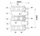
- the carbonization chamber 51, the combustion chamber 52 and the heat storage chamber 53 are constructed of a large number of bricks, and inside the combustion chamber 52, as shown in Figure 13, a number of flues (vertical flame ducts) 59 are formed along a direction (furnace length direction) perpendicular to the arrangement direction of the carbonization chamber 51 and the combustion chamber 52.
- the carbonization chamber 51 also has a kiln opening into which the extrusion ram 56a (see Figure 12) of the extruder 56 is inserted, and a kiln opening from which the red-hot coke is extruded.
- Backstays 60 made of H-shaped steel or the like are erected near these kiln openings to prevent deformation or collapse of the furnace walls.
- Patent No. 5347614 JP 2022-110682 A Patent No. 6587951 Patent No. 6280453 Patent No. 6482484 Patent No. 6502435 Patent No. 6502436 JP 2017-137447 A
- the present invention aims to solve the above problems by providing a method and device for repairing coke ovens that, when hot repairing the bricks that make up the walls of the combustion chamber of a coke oven, prevents the remaining bricks of the adjacent combustion chamber or the unrepaired parts that remain undismantled from protruding into the carbonization chamber after repair.
- the method for repairing a coke oven of the present invention is a method for repairing a combustion chamber brick of a coke oven by hot replacing two or more oven wall bricks and binder bricks from the oven mouth along the oven length direction, and is characterized by including a confirmation step of observing the unevenness of the oven wall of the combustion chamber adjacent to the combustion chamber to be replaced from the oven mouth with a three-dimensional measuring device to confirm that the protrusion amount of the oven wall of the adjacent combustion chamber is less than a predetermined value, a re-stacking step of dismantling the part of the oven wall of the combustion chamber to be replaced that needs repair and stacking new oven wall bricks and binder bricks in the dismantled area when it is confirmed in the confirmation step that the protrusion amount of the oven wall of the adjacent combustion chamber is less than the predetermined value, and a step of using a preformed oven wall refractory assembly and a preformed ceiling refractory assembly as the newly replaced oven wall and ceiling of the combustion chamber to be replaced.
- the predetermined value is 40 mm; (2) including a repair range determination step of determining the range of the oven wall bricks and binder bricks that need repair by observing the unevenness of the oven wall from the kiln mouth with a three-dimensional measuring device before dismantling the portion of the combustion chamber to be replaced that needs repair, and a step of further confirming the protrusions of the oven wall determined in the repair range determination step from the flue hole, and dismantling binder bricks up to the binder bricks that are closer to the kiln mouth than the binder bricks determined to be sound; (3) With a portion of the combustion chamber wall opened in advance, the gas hole and air hole of the existing combustion chamber are covered with a covering material, or the gas hole and air hole are covered by filling the insulation material through the flue hole at the top of the combustion chamber wall, thereby preventing falling debris from entering the heat storage chamber when the combustion chamber is dismantled and reloaded
- the furnace wall refractory assembly and the ceiling refractory assembly are transported and carried in by using a cart that travels across the furnace;
- the method includes a step of positioning the furnace wall refractory assembly and the ceiling refractory assembly in the horizontal direction by a laser beam when arranging the furnace wall refractory assembly and the ceiling refractory assembly horizontally, and a step of installing spacers to make the mortar joint thickness uniform.
- the method includes a step of installing the ceiling refractory assembly and pouring casters into the gaps around the ceiling refractory assembly to fill them.
- a coke oven repair apparatus is a coke oven repair apparatus used in the above-mentioned coke oven repair method, (1) A slide gate is provided on the top of a coke oven, and the slide gate can be moved laterally to open when the coke oven top is dismantled and close when the coke oven dismantling work is suspended, and the slide gate is provided with safety handrails around it.
- a thermal insulation structure is provided in which several types of thermal insulation materials are stacked and fixed together in an iron frame, and the thermal insulation structure is provided between the combustion chamber to be transferred and the adjacent combustion chamber in order to retain heat in the combustion chamber adjacent to the combustion chamber to be transferred and to insulate the space for the transfer work in the combustion chamber to be transferred when the coke oven is dismantled.
- a sliding scaffolding that can be attached and detached from outside the coke oven and can be connected together is provided.
- a ceiling support beam is provided, which is formed by welding and fixing a beam and a heat-insulating structure with heat-insulating material applied to the existing bricks, and which prevents the insulation and collapse of the existing bricks of an adjacent combustion chamber when dismantling the ceiling of the combustion chamber to be repaired by replacing it. is considered to be a more preferable solution.
- the coke oven repair method and repair device of the present invention by observing the condition of the adjacent combustion chamber wall before dismantling the bricks of the combustion chamber to be repaired, it is possible to determine the range of oven wall bricks and binder bricks to be appropriately repaired, and the problem of the wall of the adjacent combustion chamber protruding into the coke chamber after repair can be solved.
- FIG. 13 is a diagram for explaining repair when there is no overhang in the furnace wall of an adjacent combustion chamber.
- FIG. 13 is a diagram for explaining repair when there is no overhang in the furnace wall of an adjacent combustion chamber.
- FIG. 13 is a diagram for explaining repair when there is no overhang in the furnace wall of an adjacent combustion chamber.
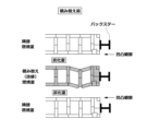
- FIG. 13 is a diagram for explaining repair when there is an overhang on the furnace wall of an adjacent combustion chamber.
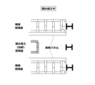
- FIG. 13 is a diagram for explaining repair when there is an overhang on the furnace wall of an adjacent combustion chamber.
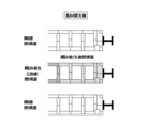
- FIG. 13 is a diagram for explaining repair when there is an overhang on the furnace wall of an adjacent combustion chamber.
- 1A and 1B are diagrams illustrating an example of a slide gate as a preferred embodiment of the coke oven repair method of the present invention.
- FIG. 1A and 1B are diagrams for explaining an example of a heat insulating structure as a preferred embodiment of a coke oven repair apparatus used in the coke oven repair method of the present invention.
- FIG. 2 is a diagram for explaining an example of pre-curing of gas holes as a preferred embodiment of the coke oven repair method of the present invention.
- 1A and 1B are diagrams for explaining an example of an in-furnace sliding scaffold as a preferred embodiment of a coke oven repair apparatus used in the coke oven repair method of the present invention.
- FIG. 2 is a diagram for explaining an example of a ceiling support beam as a preferred embodiment of a coke oven repair apparatus used in the coke oven repair method of the present invention.
- FIG. 2 is a diagram for explaining an example of a crossover MCB as a preferred embodiment of the coke oven repair method of the present invention.
- FIG. 2 is a diagram for explaining an implementation state of the first embodiment.
- FIG. 11 is a diagram for explaining the implementation state of the second embodiment.
- FIG. 13 is a diagram for explaining the implementation state of the third embodiment.
- FIG. 1 is a diagram for explaining an example of a known coke oven.
- FIG. 1 is a top view of a known coke oven.
- the present invention relates to a method and an apparatus for repairing a coke oven, and has been achieved based on the following findings.
- Conventionally, in the method for repairing a coke oven when repairing a combustion chamber to be repaired, there was a problem that the furnace wall of the combustion chamber adjacent to the combustion chamber to be repaired protrudes toward the carbonization chamber.
- the insulation panel cannot be installed properly, and as a result, the temperature of the adjacent combustion chamber drops and protrudes into the carbonization chamber.
- Figures 1A to 1C are diagrams each for explaining repairs when there is no overhang on the furnace wall of an adjacent combustion chamber.
- Figure 1A the unevenness of the furnace wall of the combustion chamber adjacent to the combustion chamber to be repaired is observed with a three-dimensional measuring device to confirm that the overhang of the furnace wall is less than a specified value.
- Figure 1B a heat insulating panel is installed on the surface of the adjacent combustion chamber facing the combustion chamber to be repaired, and the replaced part of the combustion chamber to be repaired is dismantled.
- Figure 1C the dismantled part of the combustion chamber to be repaired is replaced, and the combustion chamber to be repaired is repaired.
- the adjacent combustion chambers where it was confirmed in Figure 1A that the overhang of the furnace wall is less than the specified value, none of them have any overhang of the furnace wall, as shown in Figure 1C.
- Figures 2A to 2C are diagrams for explaining repairs when there is an overhang on the furnace wall of an adjacent combustion chamber.
- Figure 2A shows an example of an observation in which the furnace wall of the combustion chamber adjacent to the upper side of the combustion chamber to be repaired overhangs a predetermined value or more, preferably 40 mm or more, and the furnace wall of the combustion chamber adjacent to the lower side of the combustion chamber to be repaired overhangs less than a predetermined value, preferably less than 40 mm.
- an insulating panel is installed on the surface of the adjacent combustion chamber facing the combustion chamber to be repaired, and the re-installed part of the combustion chamber to be repaired is dismantled.
- the overhanging part of the furnace wall of the upper combustion chamber that overhangs 40 mm or more gets in the way when installing the insulating panel.
- the part is re-installed on the dismantled part of the combustion chamber to be repaired, and the combustion chamber to be repaired is repaired.
- the coke oven repair method of the present invention is a method for repairing the combustion chamber bricks of a coke oven by hot replacing two or more oven wall bricks and binder bricks from the oven mouth along the oven length direction, and is characterized by including a confirmation step of observing the unevenness of the oven wall of the combustion chamber adjacent to the combustion chamber to be replaced with a three-dimensional measuring device from the oven mouth to confirm that the protrusion of the oven wall of the adjacent combustion chamber is equal to or less than a predetermined value, and a re-stacking step of dismantling the portion of the oven wall of the combustion chamber to be replaced that needs repair and stacking new oven wall bricks and binder bricks in the dismantled area if it is confirmed in the confirmation step that the protrusion of the oven wall of the adjacent combustion chamber is less than the predetermined value.
- the predetermined value is preferably 40 mm.
- the adjacent combustion chamber walls will no longer protrude into the carbonization chamber after repair.
- the coke oven repair method of the present invention includes a step of using a preformed oven wall refractory assembly and a preformed ceiling refractory assembly as the oven wall and ceiling to be newly replaced in the combustion chamber to be replaced. According to this embodiment, it is possible to provide a repair method that improves the efficiency of repair work in the coke oven repair method of the present invention.
- the refractory assembly referred to here refers to firebrick blocks and fired/unfired castable blocks, etc.
- the method for repairing a coke oven of the present invention includes a repair range determination step in which, before dismantling the portion of the combustion chamber that needs repair, the range of oven wall bricks and binder bricks that need repair is determined by observing the unevenness of the oven wall from the kiln mouth with a three-dimensional measuring device, and a step in which the convex parts of the oven wall determined in the repair range determination step are further confirmed from the flue hole, and the binder bricks that are closer to the kiln mouth than the binder bricks determined to be sound are dismantled up to the binder bricks.
- the coke oven repair method of the present invention when hot repairing the bricks that make up the furnace wall of the combustion chamber of a coke oven, the remaining bricks in the unrepaired portion of the combustion chamber that is left undismantled to repair will not protrude toward the carbonization chamber after repair.
- a preferred embodiment of the repair device (slide gate): 3(a) and 3(b) are diagrams for explaining an example of a slide gate as a preferred embodiment of the method for repairing a coke oven of the present invention.
- Figures 3(a) and 3(b) are diagrams showing a combustion chamber seen from above, in which 1 is a coal loading car rail for a coal loading car that loads coal into the combustion chamber, 2-1 and 2-2 are movable slide gates that open and close an opening 3 above the furnace, 4 is a slide gate rail for moving the slide gates 2-1 and 2-2, and 5 is a safety handrail provided on each slide gate.
- the opening 3 targeted in this embodiment is formed by collapse or the like in the ceiling of the combustion chamber to be repaired.
- Slide gates 2-1, 2-2 are provided in the portion to be repaired that has the opening 3 in the ceiling of the combustion chamber to be repaired, and are removed after the repair is completed.
- the slide gates 2-1, 2-2 can move laterally along the slide gate rail 4. By moving the slide gates 2-1, 2-2 in opposite directions, the opening 3 is closed as shown in FIG. 3(a) when work is suspended, and is open as shown in FIG. 3(b) when work is being performed.
- the safety handrail 5 is provided to prevent people or objects from falling from the opening 3 when it is open, as shown in FIG. 3(b).
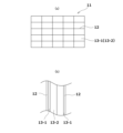
- a preferred embodiment of the repair device (thermal insulation structure): 4(a) and 4(b) are diagrams for explaining an example of a heat insulating structure as a preferred embodiment of a coke oven repair apparatus used in the coke oven repair method of the present invention.
- a heat insulating structure 11 of this embodiment is a heat insulating structure in which several types of heat insulating materials 13-1 and 13-2 are stacked and fixed in an iron frame 12 to be integrated.
- the heat insulating structure 11 is composed of a pair of biosoluble heat insulating materials 13-1 and a high-performance heat insulating material 13-2 sandwiched between the pair of biosoluble heat insulating materials 13-1, between a pair of iron frames 12.
- the high-performance heat insulating material 13-2 has a thermal conductivity of up to 0.003 W/mk, which is about 1/10 of the thermal conductivity of the biosoluble heat insulating material 13-1.
- the high-performance heat insulating material 13-2 is itself brittle.
- the high-performance heat insulating material 13-2 can be suitably fixed.
- the heat insulating structure 11 is provided only in the part of the combustion chamber to be dismantled.
- the heat insulating structure 11 of this embodiment is provided between the combustion chamber to be replaced and the adjacent combustion chamber to insulate the heat of the combustion chamber adjacent to the combustion chamber to be replaced and to insulate the space for the brick replacement work in the combustion chamber to be replaced when the coke oven is dismantled.
- the heat insulating structure 11 of this embodiment is provided on the surface facing the combustion chamber to be repaired outside the adjacent combustion chamber, thereby retaining heat in the existing oven wall (adjacent combustion chamber) and suitably insulating the space for the brick replacement work.
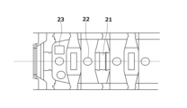
- Fig. 5 is a diagram for explaining an example of prior gas hole curing as a preferred embodiment of the coke oven repair method of the present invention.
- Fig. 5 is a diagram of the combustion chamber viewed from the top to the bottom, and at the bottom of the combustion chamber there are an M gas (mixed gas of blast furnace gas and coke gas) hole 21, a C gas (coke gas) hole 22, and an air hole 23. In this embodiment, it is preferable to cure these gas holes in advance before repair.
- M gas mixed gas of blast furnace gas and coke gas
- C gas coke gas
- the existing combustion chamber gas and air holes are covered with protective materials.
- covering with a lid is to dismantle the furnace wall bricks at the bottom of the combustion chamber to be repaired and install insulation material (iron plate or cloth) at the bottom of the combustion chamber before repairs.
- Another example of covering with a lid is to fill the combustion chamber with insulation material through the flue hole at the top of the combustion chamber to be repaired until it is completely filled. Covering of the gas holes only needs to be done in the parts that correspond to the parts of the combustion chamber to be dismantled.
- the coke oven repair method of the present invention if the pre-gas hole curing of this embodiment is performed, it is possible to prevent falling debris from being mixed into the heat storage chamber during dismantling in the combustion chamber to be repaired. This makes it possible to advantageously reduce the need to suction and remove fallen debris that has entered the heat storage chamber, which was previously necessary.
- 6(a) and 6(b) are diagrams for explaining an example of an in-oven sliding scaffold as a preferred embodiment of the coke oven repair device used in the coke oven repair method of the present invention.
- 31 is a coke oven
- 32 is an in-oven sliding scaffold installed in the coke oven.
- the in-oven sliding scaffold 32 of this embodiment is a sliding scaffold that can be attached and detached from outside the coke oven 31, with the aim of preventing a worker 33 from falling and securing a foothold during work, and has a structure that allows it to be connected and linked.
- the in-furnace sliding scaffolding 32 of this embodiment is installed in the carbonization chamber of the coke oven 31 from the mouth side to create a scaffold inside the carbonization chamber and is used to secure a foothold for workers.
- the in-furnace sliding scaffolding 32 can be connected and extended while sliding in the furnace interior direction, and can also be connected and stacked in the furnace height direction. If the in-furnace sliding scaffolding of this embodiment is used as the coke oven repair device for use in the coke oven repair method of the present invention, it is possible to prevent workers involved in repair work from falling and to secure a foothold during work.
- FIG. 7 is a diagram for explaining an example of a ceiling holding beam as a preferred embodiment of the coke oven repair device used in the coke oven repair method of the present invention.
- the ceiling holding beam 41 has a structure in which an insulating structure 44, which is an integrated structure of insulating material 42 fixed with an iron frame 43, is placed against the existing ceiling part 45 of the coke oven, and a beam 46 is welded and fixed to the iron frame 43.
- the ceiling holding beam 41 needs to be formed only in the part corresponding to the part of the combustion chamber to be dismantled.
- the ceiling support beam of this embodiment is used as the coke oven repair device for the coke oven repair method of the present invention, it is possible to effectively insulate the existing bricks and prevent them from collapsing after dismantling the ceiling of the combustion chamber to be repaired.
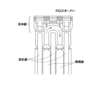
- FIG. 8 is a diagram for explaining an example of crossover MCB (Module Castable Blocks) as a preferred embodiment of the coke oven repair method of the present invention.
- Fig. 8 shows a structure that serves as a passage for exhausting combustion exhaust gas between adjacent combustion chambers.
- a one-piece or two-piece large precast block including a brick cavity is formed and stacked.
- a pair of combustion chambers are treated as one combustion chamber. Therefore, in this embodiment, repair work is performed not on each combustion chamber individually, but on a pair of combustion chambers formed integrally by stacking one-piece or two-piece precast blocks to repair brick cavities formed in the ceilings of adjacent combustion chambers. This means that the coke oven repair method of the present invention can be suitably applied even to coke ovens with a crossover MCB.
- a more preferred embodiment is a coke oven repair method and coke oven repair apparatus using techniques already publicly known in patent publications and published publications, as exemplified below.
- the method for repairing a coke oven of the present invention preferably includes a step of installing an insulating panel by placing the insulating panel on a transport cart and pulling it with a towing wire into a specified carbonization chamber and stopping it, or by pushing it out with an extruder and stopping it, before dismantling the portion of the combustion chamber that needs repair, before transferring it to another place.
- an insulating wall for protecting workers when repairing the entire length of the combustion chamber wall from the pusher side to the fire truck side of the coke oven, an insulating wall for protecting workers can be installed in the oven in a short time and at low cost.
- the coke oven repair method of the present invention preferably includes a step of using a demolition heavy machinery cart when dismantling the portion of the combustion chamber to be reloaded that requires repair.
- the demolition heavy machinery can be easily transported to the location where the walls and ceiling of the coke oven combustion chamber are to be dismantled. As a result, it becomes possible to carry out the demolition work efficiently and safely, shortening the construction period and reducing construction costs.
- the method for repairing a coke oven of the present invention preferably includes a step of using a cart that travels across the oven to transport the oven wall refractory assembly and the ceiling refractory assembly.
- the method for repairing a coke oven of the present invention it is possible to efficiently transport modular blocks for constructing new walls and ceilings of the combustion chamber of the coke oven to the repair site, and further to easily and safely carry the modular blocks and castable blocks into the oven.
- the coke oven repair method of the present invention preferably includes a step of positioning the oven wall refractory assemblies and ceiling refractory assemblies horizontally using a laser beam when arranging them horizontally, and a step of installing spacers to keep the mortar joint thickness constant.
- the coke oven repair method of the present invention can prevent deformation or collapse of walls constructed by stacking modular blocks.
- the method for repairing a coke oven of the present invention preferably includes a step of installing a ceiling refractory assembly when forming a new ceiling to be replaced, and then pouring casters into the gaps around the ceiling refractory assembly to fill them.
- the method for repairing a coke oven of the present invention can efficiently repair the ceilings of the carbonization chamber and combustion chamber of the coke oven in a short time.
- Patent Document 8 JP Patent Publication 2017-137447
- the method for repairing a coke oven of the present invention makes it possible to efficiently carry out repair work on the combustion chamber of a coke oven, thereby shortening the construction period, reducing the workload, and improving safety, and also improving durability after repair.
- Example 1 As shown in Fig. 9, for the combustion chamber to be repaired and the two combustion chambers adjacent to the combustion chamber to be repaired that constitute the coke oven, the unevenness of the furnace walls was measured using a laser scanner at a predetermined position of the kiln mouth bricks of the adjacent combustion chambers before and after the combustion chamber to be repaired was replaced. In addition, before the combustion chamber to be repaired was replaced, the presence or absence of cracks was observed from the flue hole. The results are shown in Table 1 below.
- Example 2 As shown in Fig. 10, in an example in which bricks to prevent kiln mouth extension were placed between a combustion chamber to be repaired and two combustion chambers adjacent to the combustion chamber to be repaired that constitute a coke oven, a laser scanner was used to measure the unevenness of the oven wall at a specified position of the kiln mouth bricks of the adjacent combustion chambers before and after the bricks were replaced with the combustion chamber to be repaired. In addition, before the combustion chamber to be repaired was replaced, the presence or absence of cracks was observed from the flue hole. The results are shown in Table 2 below.
Landscapes
- Chemical & Material Sciences (AREA)
- Engineering & Computer Science (AREA)
- Materials Engineering (AREA)
- Oil, Petroleum & Natural Gas (AREA)
- Organic Chemistry (AREA)
- Furnace Housings, Linings, Walls, And Ceilings (AREA)
Priority Applications (3)
| Application Number | Priority Date | Filing Date | Title |
|---|---|---|---|
| PCT/JP2023/031191 WO2025046733A1 (ja) | 2023-08-29 | 2023-08-29 | コークス炉の補修方法および補修装置 |
| PCT/JP2024/025252 WO2025047148A1 (ja) | 2023-08-29 | 2024-07-12 | コークス炉の補修方法および補修装置 |
| JP2024562153A JPWO2025047148A1 (https=) | 2023-08-29 | 2024-07-12 |
Applications Claiming Priority (1)
| Application Number | Priority Date | Filing Date | Title |
|---|---|---|---|
| PCT/JP2023/031191 WO2025046733A1 (ja) | 2023-08-29 | 2023-08-29 | コークス炉の補修方法および補修装置 |
Publications (1)
| Publication Number | Publication Date |
|---|---|
| WO2025046733A1 true WO2025046733A1 (ja) | 2025-03-06 |
Family
ID=94818503
Family Applications (2)
| Application Number | Title | Priority Date | Filing Date |
|---|---|---|---|
| PCT/JP2023/031191 Pending WO2025046733A1 (ja) | 2023-08-29 | 2023-08-29 | コークス炉の補修方法および補修装置 |
| PCT/JP2024/025252 Pending WO2025047148A1 (ja) | 2023-08-29 | 2024-07-12 | コークス炉の補修方法および補修装置 |
Family Applications After (1)
| Application Number | Title | Priority Date | Filing Date |
|---|---|---|---|
| PCT/JP2024/025252 Pending WO2025047148A1 (ja) | 2023-08-29 | 2024-07-12 | コークス炉の補修方法および補修装置 |
Country Status (2)
| Country | Link |
|---|---|
| JP (1) | JPWO2025047148A1 (https=) |
| WO (2) | WO2025046733A1 (https=) |
Citations (15)
| Publication number | Priority date | Publication date | Assignee | Title |
|---|---|---|---|---|
| JPS4923562B1 (https=) * | 1970-11-17 | 1974-06-17 | ||
| JPS5351107A (en) * | 1976-10-21 | 1978-05-10 | Sugagumi Kouji Kk | Cornice deck for prevention of fall |
| JPS5798589A (en) * | 1980-12-10 | 1982-06-18 | Sumikin Coke Co Ltd | Method for preventing drop in temperature of horizontal cross passage and regenerative chamber during hot stacking and replacing operation of coke oven |
| JP2000313882A (ja) * | 1999-03-03 | 2000-11-14 | Sumitomo Metal Ind Ltd | コークス炉炉壁煉瓦熱間積替え時の非積替え煉瓦の拘束方法 |
| JP2003239531A (ja) * | 2002-02-14 | 2003-08-27 | Mitsubishi Heavy Ind Ltd | 足 場 |
| JP2004203966A (ja) * | 2002-12-24 | 2004-07-22 | Kansai Coke & Chem Co Ltd | コークス炉炉壁状況の評価方法 |
| JP2013082909A (ja) * | 2011-09-28 | 2013-05-09 | Jfe Steel Corp | コークス炉の炉壁診断方法およびコークス炉の炉壁補修方法 |
| JP2017137447A (ja) * | 2016-02-05 | 2017-08-10 | 株式会社メガテック | コークス炉の燃焼室の補修方法 |
| JP6280453B2 (ja) * | 2014-06-11 | 2018-02-14 | 株式会社メガテック | コークス炉燃焼室の壁体と天井およびその燃焼室に隣接する炭化室の天井の補修方法 |
| JP6482484B2 (ja) * | 2016-02-05 | 2019-03-13 | 株式会社メガテック | コークス炉の補修用のモジュールブロックを運搬する炉上台車 |
| JP6502435B2 (ja) * | 2017-08-23 | 2019-04-17 | 株式会社メガテック | コークス炉補修用のモジュールブロックの水平配列方法 |
| JP6502436B2 (ja) * | 2017-08-23 | 2019-04-17 | 株式会社メガテック | コークス炉の天井の補修方法 |
| JP6587951B2 (ja) * | 2016-02-05 | 2019-10-09 | 株式会社メガテック | コークス炉燃焼室の解体用重機を運搬する重機台車 |
| JP2022110682A (ja) * | 2021-01-19 | 2022-07-29 | 株式会社メガテック | コークス炉補修用断熱壁の設置方法 |
| WO2023064916A1 (en) * | 2021-10-15 | 2023-04-20 | Vanocur Refractories Llc | Cross over duct for heating walls of a coke oven or coke oven battery |
Family Cites Families (2)
| Publication number | Priority date | Publication date | Assignee | Title |
|---|---|---|---|---|
| JPS59187082A (ja) * | 1983-04-08 | 1984-10-24 | Nippon Steel Corp | コ−クス炉炭化室炉底煉瓦の補修法 |
| JP5347614B2 (ja) | 2009-03-19 | 2013-11-20 | Jfeスチール株式会社 | コークス炉の熱間補修方法 |
-
2023
- 2023-08-29 WO PCT/JP2023/031191 patent/WO2025046733A1/ja active Pending
-
2024
- 2024-07-12 JP JP2024562153A patent/JPWO2025047148A1/ja active Pending
- 2024-07-12 WO PCT/JP2024/025252 patent/WO2025047148A1/ja active Pending
Patent Citations (15)
| Publication number | Priority date | Publication date | Assignee | Title |
|---|---|---|---|---|
| JPS4923562B1 (https=) * | 1970-11-17 | 1974-06-17 | ||
| JPS5351107A (en) * | 1976-10-21 | 1978-05-10 | Sugagumi Kouji Kk | Cornice deck for prevention of fall |
| JPS5798589A (en) * | 1980-12-10 | 1982-06-18 | Sumikin Coke Co Ltd | Method for preventing drop in temperature of horizontal cross passage and regenerative chamber during hot stacking and replacing operation of coke oven |
| JP2000313882A (ja) * | 1999-03-03 | 2000-11-14 | Sumitomo Metal Ind Ltd | コークス炉炉壁煉瓦熱間積替え時の非積替え煉瓦の拘束方法 |
| JP2003239531A (ja) * | 2002-02-14 | 2003-08-27 | Mitsubishi Heavy Ind Ltd | 足 場 |
| JP2004203966A (ja) * | 2002-12-24 | 2004-07-22 | Kansai Coke & Chem Co Ltd | コークス炉炉壁状況の評価方法 |
| JP2013082909A (ja) * | 2011-09-28 | 2013-05-09 | Jfe Steel Corp | コークス炉の炉壁診断方法およびコークス炉の炉壁補修方法 |
| JP6280453B2 (ja) * | 2014-06-11 | 2018-02-14 | 株式会社メガテック | コークス炉燃焼室の壁体と天井およびその燃焼室に隣接する炭化室の天井の補修方法 |
| JP2017137447A (ja) * | 2016-02-05 | 2017-08-10 | 株式会社メガテック | コークス炉の燃焼室の補修方法 |
| JP6482484B2 (ja) * | 2016-02-05 | 2019-03-13 | 株式会社メガテック | コークス炉の補修用のモジュールブロックを運搬する炉上台車 |
| JP6587951B2 (ja) * | 2016-02-05 | 2019-10-09 | 株式会社メガテック | コークス炉燃焼室の解体用重機を運搬する重機台車 |
| JP6502435B2 (ja) * | 2017-08-23 | 2019-04-17 | 株式会社メガテック | コークス炉補修用のモジュールブロックの水平配列方法 |
| JP6502436B2 (ja) * | 2017-08-23 | 2019-04-17 | 株式会社メガテック | コークス炉の天井の補修方法 |
| JP2022110682A (ja) * | 2021-01-19 | 2022-07-29 | 株式会社メガテック | コークス炉補修用断熱壁の設置方法 |
| WO2023064916A1 (en) * | 2021-10-15 | 2023-04-20 | Vanocur Refractories Llc | Cross over duct for heating walls of a coke oven or coke oven battery |
Also Published As
| Publication number | Publication date |
|---|---|
| JPWO2025047148A1 (https=) | 2025-03-06 |
| WO2025047148A1 (ja) | 2025-03-06 |
Similar Documents
| Publication | Publication Date | Title |
|---|---|---|
| US6539602B1 (en) | Method of repairing coke oven | |
| US11845898B2 (en) | System and method for repairing a coke oven | |
| JP6008071B1 (ja) | コークス炉の建設方法 | |
| JP6280453B2 (ja) | コークス炉燃焼室の壁体と天井およびその燃焼室に隣接する炭化室の天井の補修方法 | |
| JP3397723B2 (ja) | コークス炉の補修方法 | |
| JP6844332B2 (ja) | 室炉式コークス炉の炉頂部の築造方法、及び室炉式コークス炉の炉頂部構造 | |
| CN101842655A (zh) | 耐火炉中的加热壁的修补 | |
| WO2025046733A1 (ja) | コークス炉の補修方法および補修装置 | |
| JP7594920B2 (ja) | コークス炉補修用断熱壁の設置方法 | |
| JP2000313882A (ja) | コークス炉炉壁煉瓦熱間積替え時の非積替え煉瓦の拘束方法 | |
| JP4049310B2 (ja) | コークス炉炭化室壁の熱間補修方法 | |
| JP7356038B2 (ja) | 耐火物ブロック及びその設置方法 | |
| JP3933211B2 (ja) | 熱風炉の補修工事方法 | |
| JP3421280B2 (ja) | コークス炉レンガ補修時の炉内断熱方法 | |
| JP4851127B2 (ja) | 断熱ボックスの挿入方法および挿入装置 | |
| JP2020070341A (ja) | コークス炉の解体建設方法 | |
| WO2025046734A1 (ja) | コークス炉の補修方法 | |
| JP6543310B2 (ja) | コークス炉のピニオンウォールに隣接する燃焼室の構築方法 | |
| JP2020117559A (ja) | コークス炉構築工法及びコークス炉構築用仮設構台 |
Legal Events
| Date | Code | Title | Description |
|---|---|---|---|
| 121 | Ep: the epo has been informed by wipo that ep was designated in this application |
Ref document number: 23950683 Country of ref document: EP Kind code of ref document: A1 |