WO2025041266A1 - Dispositif de gestion de filtre - Google Patents
Dispositif de gestion de filtre Download PDFInfo
- Publication number
- WO2025041266A1 WO2025041266A1 PCT/JP2023/030159 JP2023030159W WO2025041266A1 WO 2025041266 A1 WO2025041266 A1 WO 2025041266A1 JP 2023030159 W JP2023030159 W JP 2023030159W WO 2025041266 A1 WO2025041266 A1 WO 2025041266A1
- Authority
- WO
- WIPO (PCT)
- Prior art keywords
- filter
- rotation speed
- oil mist
- fan motor
- concentration
- Prior art date
- Legal status (The legal status is an assumption and is not a legal conclusion. Google has not performed a legal analysis and makes no representation as to the accuracy of the status listed.)
- Pending
Links
Images




Classifications
-
- B—PERFORMING OPERATIONS; TRANSPORTING
- B23—MACHINE TOOLS; METAL-WORKING NOT OTHERWISE PROVIDED FOR
- B23Q—DETAILS, COMPONENTS, OR ACCESSORIES FOR MACHINE TOOLS, e.g. ARRANGEMENTS FOR COPYING OR CONTROLLING; MACHINE TOOLS IN GENERAL CHARACTERISED BY THE CONSTRUCTION OF PARTICULAR DETAILS OR COMPONENTS; COMBINATIONS OR ASSOCIATIONS OF METAL-WORKING MACHINES, NOT DIRECTED TO A PARTICULAR RESULT
- B23Q11/00—Accessories fitted to machine tools for keeping tools or parts of the machine in good working condition or for cooling work; Safety devices specially combined with or arranged in, or specially adapted for use in connection with, machine tools
- B23Q11/10—Arrangements for cooling or lubricating tools or work
-
- B—PERFORMING OPERATIONS; TRANSPORTING
- B23—MACHINE TOOLS; METAL-WORKING NOT OTHERWISE PROVIDED FOR
- B23Q—DETAILS, COMPONENTS, OR ACCESSORIES FOR MACHINE TOOLS, e.g. ARRANGEMENTS FOR COPYING OR CONTROLLING; MACHINE TOOLS IN GENERAL CHARACTERISED BY THE CONSTRUCTION OF PARTICULAR DETAILS OR COMPONENTS; COMBINATIONS OR ASSOCIATIONS OF METAL-WORKING MACHINES, NOT DIRECTED TO A PARTICULAR RESULT
- B23Q17/00—Arrangements for observing, indicating or measuring on machine tools
Definitions
- This disclosure relates to a filter management device that manages the filters of a mist collector.
- the filter management device comprises a receiving unit that receives concentration information indicating the oil mist concentration from a concentration meter that measures the oil mist concentration in the working chamber of the machine tool, a rotation speed control unit that controls the rotation speed of a fan motor of a mist collector that collects the oil mist in the working chamber using a filter based on the received concentration information, a determination unit that determines whether a filter abnormality has occurred or the need for filter replacement based on the controlled fan motor rotation speed, and a warning generation unit that generates a warning when it is determined that a filter abnormality has occurred or the filter needs replacing.
- FIG. 1 is a diagram showing a filter management system including a filter management device according to the present embodiment.
- FIG. 2 is a hardware configuration diagram of the filter management device according to this embodiment.
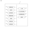
- FIG. 3 is a functional block diagram of the filter management device according to the present embodiment.
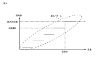
- FIG. 4 is a diagram showing an example of a pattern of the rotation speed control of the fan motor by the rotation speed control unit of FIG.
- FIG. 5 is a diagram showing another example of a pattern of the rotation speed control of the fan motor by the rotation speed control unit of FIG.
- FIG. 6 is a diagram showing an example of a threshold information management table stored in the storage unit of FIG.
- FIG. 7 is a supplementary diagram for explaining an example of the determination process by the determination unit in FIG.
- FIG. 8 is a supplementary diagram for explaining another example of the determination process by the determination unit in FIG.
- FIG. 9 is a diagram showing another example of the threshold information management table stored in the storage unit of FIG.
- Machine tool is a device that performs a predetermined process such as manufacturing a molded part, or joining a molded part to a supplied workpiece, machining, etc.
- the machine tool refers to various devices that generate oil mist during operation, such as a turning machine or a cutting machine.
- a machining room is a space that is partitioned from the outside by a cover that covers the entire machining tool.
- the machining room is one element that constitutes a machine tool.
- the machining room may be a room in which the machine tool is located.
- Concentration meter A device for measuring the oil mist concentration in a machining chamber.
- the concentration meter is an external device independent of the machine tool.
- the concentration meter may be an element constituting the machine tool.
- Mist collector A device for collecting oil mist in the machining chamber. In this embodiment, it is a filter type mist collector.
- the filter management device has the function of determining whether an abnormality has occurred in the filter installed in the mist collector or whether the filter needs to be replaced.
- the basic principle of this determination process is as follows. Filters with reduced filter performance, such as filters with an abnormality or filters that are clogged to the point of needing replacement, are collectively referred to as abnormal filters.
- the oil mist generation conditions under which oil mist is generated in the work chamber such as the concentration, amount, and timing of the oil mist generated in the work chamber
- the oil mist collection conditions under which oil mist is collected such as the amount of oil mist collected in the work chamber and the change over time in the collection amount
- the filter management device uses the basic principles of the above-mentioned judgment process to determine whether a filter abnormality has occurred or whether the filter needs to be replaced, on the premise that the rotation speed of the mist collector fan motor is controlled according to the oil mist concentration.
- the rotation speed refers to the number of rotations per unit time.
- a filter management device 2 is a device that functions as the core of a filter management system 1.
- the filter management system 1 has the filter management device 2, a machine tool 5, a concentration meter 6, and a mist collector 7.
- the machine tool 5 has a work room 52 and a control panel 55 that controls the entire machine tool 5.
- the control panel 55 has a function to set machining conditions and a function to control the operation of the machining tools in the work room 52 in accordance with the machining conditions.
- the control panel 55 also has a function to transmit data regarding the machining conditions to the filter management device 2 in response to a request to obtain machining conditions from the filter management device 2.
- the control panel 55 is realized by a numerical control device, a PC, or the like.
- the machining conditions here include conditions that can change the concentration, amount, timing, etc. of the oil mist generated in the work room when the machine tool 5 operates in accordance with the machining conditions. Examples of such conditions include machining time, machining speed, type of lubricant, and amount of lubricant supplied.
- the concentration meter 6 measures the oil mist concentration in the work chamber 52 and transmits concentration information indicating the oil mist concentration to the filter management device 2 .
- the mist collector 7 has a housing 72 installed outside the work chamber 52. The work chamber 52 and the housing 72 are connected by a duct 71. Inside the housing 72, a fan 75 for sucking the air in the work chamber 52 together with the oil mist, a filter 73 for recovering the oil mist from the air sucked by the fan 75, and a fan motor 77 for driving the fan 75 are arranged. Inside or outside the housing 72, a driver (not shown) for controlling the rotation speed of the fan motor 77 is arranged.
- the driver generates a drive current according to a command value of the rotation speed (referred to as a rotation speed command value) input from an input device (not shown) provided in the mist collector 7 or a filter management device 2 connected to the mist collector 7.
- the drive current generated by the driver is supplied to the fan motor 77.
- the fan motor 77 rotates at the rotation speed according to the command value.
- FIG. 2 is a hardware configuration diagram of the filter management device 2.
- the filter management device 2 is configured by connecting a RAM 12, a ROM 13, a storage device 14, a mist collector I/F 15, a concentration meter I/F 16, a machine tool I/F 17, an input device 18, a display device 19, a speaker 20, and a signal light 21 to a processor 11 via a data/control bus 10.
- the processor 11 is realized by a CPU, a GPU, etc.
- the RAM 12 functions as the main memory, work area, etc. of the processor 11.
- the ROM 13 stores the BIOS, OS, etc.
- the storage device 14 stores a filter management program. The various data stored in the storage device 14 may be recorded on removable media and distributed to users, or may be distributed by being downloaded to the filter management device 2 via a network.
- the mist collector 7 is connected to the mist collector I/F 15.
- a rotation speed command value for the fan motor 77 is input from the filter management device 2 to the mist collector 7 via the mist collector I/F 15.
- the concentration meter 6 is connected to the concentration meter I/F 16.
- Concentration information indicating the oil mist concentration is input from the concentration meter 6 to the filter management device 2 via the concentration meter I/F 16.
- the machine tool 5 is connected to the machine tool I/F 17.
- a request to obtain the machining conditions that are planned to be used or are currently being used is input from the filter management device 2 to the machine tool 5 via the machine tool I/F 17, and the machining conditions corresponding to the request are input from the machine tool 5 to the filter management device 2.
- the input device 18 is realized by a keyboard, a mouse, a jog, etc.
- a user can input various information to the filter management device 2 via the input device 18.
- the display device 19 is realized by an organic EL display, an LCD, etc.
- the display device 19 displays various screens according to the control of the processor 11.
- the speaker 20 generates sound to notify the user of a warning or alarm according to the control of the processor 11.
- the signal light 21 lights up to notify the user of a warning or alarm according to the control of the processor 11.
- FIG. 3 is a functional block diagram of the filter management device 2.
- the filter management device 2 When the filter management program loaded from the storage device 14 to the RAM 12 is executed by the processor 11, the filter management device 2 functions as an input unit 30, a processing condition receiving unit 31, a concentration information receiving unit 32, a storage unit 33, a screen creating unit 34, a display unit 35, a condition setting unit 36, a rotation speed control unit 37, a determination unit 38, a sound generating unit 39, and a signal generating unit 40.
- the input unit 30 is a function related to the input device 18 in FIG. 2, and inputs user operations to the filter management device 2.
- the machining condition receiving unit 31 receives machining conditions from the control panel 55 of the machine tool 5.
- the concentration information receiving unit 32 receives concentration information indicating the oil mist concentration from the concentration meter 6.
- the memory unit 33 is a function related to the storage device 14 in FIG. 2, and stores various information related to the processing of the filter management program. Specifically, the memory unit 33 stores data of a threshold information management table that summarizes threshold information. The threshold information management table will be described in detail later.
- the screen creation unit 34 displays various screens related to the filter management program. Specifically, the screen creation unit 34 creates a condition setting screen, a warning screen, and the like.
- the condition setting screen is configured to be able to set a pattern for controlling the rotation speed of the fan motor 77.
- the warning screen is created when the determination unit 38 determines that an abnormality has occurred in the filter 73 or that replacement of the filter 73 is necessary.
- the warning screen is configured to allow the user to recognize that an abnormality has occurred in the filter 73 or that replacement of the filter 73 is necessary.
- the warning screen may be configured to include a mark or text information indicating that an abnormality has occurred in the filter 73 or that replacement of the filter 73 is necessary, or the warning screen may be configured so that all or part of it is a warning color such as red or yellow.
- the display unit 35 is a function related to the display device 19 in FIG. 2, and displays the condition setting screen, warning screen, etc. created by the screen creation unit 34. In other words, the display unit 35 functions as a warning generation unit that generates a warning.
- the condition setting unit 36 sets a pattern for controlling the rotation speed of the fan motor 77 according to user operations on the condition setting screen.
- the rotation speed control unit 37 controls the fan motor 77 according to the rotation speed control pattern set by the user. Specifically, the rotation speed control unit 37 uses the set rotation speed control pattern to identify a rotation speed according to the oil mist concentration, and creates a rotation speed command value for rotating the fan motor 77 at the identified rotation speed. The rotation speed command value created by the rotation speed control unit 37 is sent to the mist collector 7.
- the determination unit 38 determines whether an abnormality has occurred in the filter 73 or whether replacement of the filter 73 is necessary based on the rotation speed of the fan motor 77. Details of the determination process by the determination unit 38 will be described later.
- the rotation speed of the fan motor 77 used in the determination process by the determination unit 38 is the rotation speed represented by a rotation speed command value generated by a rotation speed control unit 37 described later and transmitted to the mist collector 7, that is, the planned value of the rotation speed at which the fan motor 77 will rotate.
- the rotation speed of the fan motor 77 used in the determination process by the determination unit 38 may also be the rotation speed based on the output of an encoder (not shown) equipped on the fan motor 77, that is, the actual rotation speed of the fan motor 77.
- the sound generating unit 39 generates a predetermined sound (alarm sound) for notifying the user of an alarm when the determination unit 38 determines that an abnormality has occurred in the filter 73 or that replacement of the filter 73 is necessary.
- the sound generating unit 39 also generates a predetermined sound (warning sound) for notifying the user of a warning when the determination unit 38 determines that there is a sign of an abnormality occurring in the filter 73 or that the time to replace the filter 73 is approaching.
- the sound generating unit 39 functions as a warning generating unit that generates a warning.
- the signal generating unit 40 generates a first signal for turning on the signal light 21 in the first mode when the determining unit 38 determines that an abnormality has occurred in the filter 73 or that the filter 73 needs to be replaced.
- the signal generating unit 40 generates a second signal for turning on the signal light 21 in the second mode when the determining unit 38 determines that there is a sign of an abnormality occurring in the filter 73 or that the time to replace the filter 73 is approaching.
- the first signal turns on the signal light 21 in red
- the second signal turns on the signal light 21 in yellow.
- the first mode is different from the second mode, but may be the same as the second mode.
- the signal generating unit 40 functions as a warning generating unit that generates a warning.
- Figure 4 shows an example of a control pattern in which the rotation speed of the fan motor 77 is changed in stages in accordance with fluctuations in the oil mist concentration.
- the first pattern indicates that when the oil mist concentration is equal to or higher than concentration B1, the fan motor 77 rotates at the maximum rotation speed, and the rotation speed of the fan motor 77 is changed in five stages in accordance with fluctuations in the oil mist concentration until the rotation speed of the fan motor 77 reaches the maximum rotation speed.
- FIG. 5 shows an example of a control pattern for continuously changing the rotation speed of the fan motor 77 in accordance with the variation in the oil mist concentration.
- the second, third and fourth patterns indicate that the fan motor 77 rotates at the maximum rotation speed when the oil mist concentration is equal to or higher than concentration B1.
- the second pattern indicates that the rotation speed of the fan motor 77 increases linearly in accordance with the variation in the oil mist concentration until the rotation speed of the fan motor 77 reaches the maximum rotation speed.
- the third pattern indicates that the rotation speed of the fan motor 77 increases quadratically in accordance with the variation in the oil mist concentration until the rotation speed of the fan motor 77 reaches the maximum rotation speed.
- the fourth pattern indicates that while the oil mist concentration is low, the rotation speed of the fan motor 77 increases linearly little by little in accordance with the variation in the oil mist concentration, and when the oil mist concentration increases, the rotation speed of the fan motor 77 increases linearly and greatly in accordance with the variation in the oil mist concentration.
- the maximum rotation speed is not the maximum rotation speed in the specifications of the fan motor 77, but the maximum rotation speed controlled by the filter management device 2.
- the maximum rotation speed controlled by the filter management device 2 may also be the maximum rotation speed in the specifications of the fan motor 77.
- FIG. 6 is a diagram showing an example of the threshold management table stored in the memory unit 33.
- the processing conditions, the rotation speed control pattern, and the duration of the maximum rotation speed are associated with the management number.
- the duration of the maximum rotation speed is the time during which the state in which the rotation speed of the fan motor 77 indicates the maximum rotation speed continues, and is a threshold used in the judgment process of the judgment unit 38.
- the management number "001" indicates that the threshold value of the time during which the state in which the rotation speed of the fan motor 77 indicates the maximum rotation speed continues when the machine tool 5 operates according to the first processing conditions and the rotation speed of the fan motor 77 of the mist collector 7 is controlled according to the first pattern is T11.
- the threshold value is a threshold value for judging the occurrence of an abnormality in the filter 73 or the need to replace the filter 73.
- the threshold value T11 corresponds to the time during which the state in which the rotation speed of the fan motor 77 indicates the maximum rotation speed continues when the machine tool 5 operates according to the first machining condition, the rotation speed of the fan motor 77 of the mist collector 7 is controlled according to the first pattern, and an abnormal filter 73 is used as the filter 73 of the mist collector 7.
- the threshold value T11 may be a value actually measured using the abnormal filter 73, or may be a calculated value derived based on a simulation or the like.
- the conditions for generating oil mist in the machining chamber 52 such as the concentration, amount, and timing, change due to changes in the machining conditions, it is desirable to set a threshold value for each machining condition of the machine tool 5. If the recovery conditions, such as the amount and speed of oil mist collected, change due to changes in the pattern of control of the rotation speed of the fan motor 77, it is desirable to set a threshold value for each control pattern.
- FIG. 7 is a supplementary diagram for explaining an example of the determination process by the determination unit 38, and is a graph showing the change over time in the oil mist concentration measured by the concentration meter 6. Both of the two graphs 200, 300 show the change over time in the oil mist concentration when the first machining conditions are set for the machine tool 5 and the first pattern of rotation speed control is set for the fan motor 77. As shown in FIG. 4, the threshold value when the first machining conditions are set for the machine tool 5 and the first pattern is set for the fan motor 77 is T11.
- the determination unit 38 compares the duration Tm1 during which the rotation speed of the fan motor 77 remains at the maximum rotation speed in the first graph 200 with the threshold value T11. Because the duration Tm1 in the first graph 200 is less than the threshold value T11, the determination unit 38 determines that the filter 73 used in the mist collector 7 when the first graph 200 was obtained is a normal filter 73, and that no abnormality has occurred or that replacement of the filter 73 is not required.
- the determination unit 38 compares the duration Tm2 during which the rotation speed of the fan motor 77 in the second graph 300 remains at the maximum rotation speed with the threshold value T11. Because the duration Tm2 in the second graph 300 is equal to or greater than the threshold value T11, the determination unit 38 determines that an abnormality has occurred in the filter 73 used in the mist collector 7 when the second graph 300 was obtained, or that the filter 73 needs to be replaced.
- the filter management device 2 can determine whether an abnormality has occurred in the filter 73 or whether replacement of the filter 73 is necessary based on the rotation speed of the controlled fan motor 77.
- the user can be notified of this by an alarm sound, a signal light being turned on, or a warning screen being displayed.
- This allows the user to grasp the state of the filter 73, and can avoid situations in which a filter 73 with low oil mist collection efficiency is continued to be used for an extended period of time due to the inability to grasp the state of the filter 73 as in the past, or where the filter 73 is replaced even though the filter performance has not yet deteriorated.
- the user can replace the filter at a more appropriate time from the viewpoint of using up the filter 73.
- the above-mentioned determination process by the filter management device 2 according to this embodiment can be realized if the change over time in the oil mist concentration in the work chamber 52 and the rotation speed of the fan motor 77 of the mist collector 7 can be acquired, so there is no need to install new sensors, etc., and the introduction cost of the technology according to this embodiment can be said to be very low.
- the time during which the rotational speed of the fan motor 77 continues to indicate the maximum rotational speed is used as a judgment parameter for judging the occurrence of an abnormality in the filter 73 based on the rotational speed of the fan motor 77 or the need to replace the filter 73.
- This utilizes the fact that, if the generation conditions of the oil mist generated in the work chamber 52 and the collection conditions of the oil mist generated in the work chamber 52 are the same, the oil mist concentration in the work chamber 52 when a filter 73 having an abnormality is used in the mist collector 7 is less likely to decrease than the oil mist concentration in the work chamber 52 when a normal filter 73 is used in the mist collector 7.
- the judgment parameter is not limited to the time during which the rotational speed of the fan motor 77 continues to indicate the maximum rotational speed.
- it may be the time during which the rotation speed of the fan motor 77 continues to be equal to or greater than a predetermined rotation speed that is lower than the maximum rotation speed.
- FIG. 8 is a supplementary diagram for explaining another example of the judgment process by the judgment unit 38, and is a graph showing the change in oil mist concentration over time measured by the concentration meter 6.
- the first and second graphs 200 and 300 in FIG. 8 are the same graphs as FIG. 7.
- the judgment unit 38 calculates the gradient of the change in oil mist concentration over time, and when the calculated gradient is steeper than a threshold value, judges that an abnormality has occurred in the filter 73 or that the filter 73 needs to be replaced.
- the judgment unit 38 calculates gradients Gr2 and Gr3 for the first and second graphs 200 and 300, respectively, based on multiple measured values in which the oil mist concentration falls within the range from B2 to B1, and compares them with the threshold value. For example, if the gradient Gr2 is gentler than the threshold, the determination unit 38 determines that the filter 73 used in the mist collector 7 when the first graph 200 was acquired is a normal filter 73, and that no abnormality has occurred or that replacement of the filter 73 is not required. Similarly, if the gradient Gr3 is steeper than the threshold, the determination unit 38 determines that the filter 73 used in the mist collector 7 when the second graph 300 was acquired is abnormal or that replacement of the filter 73 is required.
- the range of the measured values used to calculate the gradient is not limited to the above.
- it may be a range in which the rotation speed of the fan motor 77 is equal to or greater than a predetermined rotation speed and the oil mist concentration reaches a maximum concentration.
- FIG. 9 is a diagram showing another example of a threshold management table stored in the memory unit 33.
- the processing conditions, the rotation speed control pattern, the first duration of the maximum rotation speed, and the second duration of the maximum rotation speed are associated with the management number.
- the first duration of the maximum rotation speed (first threshold value) is a threshold value for determining whether an abnormality has occurred in the filter 73 or whether it is necessary to replace the filter 73.
- the second duration of the maximum rotation speed is a threshold value for determining whether an abnormality has occurred in the filter 73 or whether it is near the time to replace the filter 73.
- the second threshold value may be obtained by actual measurement, like the first threshold value, or may be a calculated value derived by simulation or the like.
- the determination unit 38 compares the duration Tm1 during which the fan motor 77 continues to rotate at the maximum speed in the first graph 200 with the first threshold value T11 and the second threshold value T12. When the duration Tm1 in the first graph 200 is smaller than the first threshold value T11 and equal to or greater than the second threshold value T12, the determination unit 38 determines that there is a sign of an abnormality occurring in the filter 73 used in the mist collector 7 when the first graph 200 was acquired, or that the time to replace the filter 73 is approaching.
- the display unit 35 displays a screen to notify the user of this, and the sound generation unit 39 generates a sound different from that generated when the determination unit 38 determines that an abnormality has occurred in the filter 73 or that the filter 73 needs to be replaced.
- the condition of the filter 73 can be determined in more detail.
- the degree of clogging may also be displayed. This allows the user to grasp the condition of the filter 73 currently in use in more detail, and allows the user to prepare the filter 73 and plan a filter replacement schedule in advance. This contributes to improving the efficiency of the user's filter replacement work.
- the filter management device 2 comprises a receiving unit 32 that receives concentration information indicating the oil mist concentration from a concentration meter 6 that measures the oil mist concentration in the work chamber 52 of the machine tool 5, a rotation speed control unit 37 that controls the rotation speed of a fan motor 77 of a mist collector 7 that collects the oil mist in the work chamber 52 using a filter 73 based on the received concentration information, a determination unit 38 that determines whether an abnormality has occurred in the filter 73 or the need for replacement of the filter 73 based on the controlled rotation speed of the fan motor 77, and warning generating units 35, 39 that generate a warning when it is determined that an abnormality has occurred in the filter or that replacement of the filter 73 is necessary.
- the judgment unit 38 judges that there is a sign of an abnormality occurring in the filter 73 or that the time to replace the filter 73 is approaching when the gradient of the change in oil mist concentration over time is between a first threshold value and a second threshold value lower than the first threshold value.
- the predetermined rotation speed or more is the maximum rotation speed at which the rotation speed control unit 37 controls the fan motor 77.
- 1...filter management system 2...filter management device, 5...machine tool, 6...concentration meter, 7...mist collector, 10...data/control bus, 11...processor, 12...RAM, 13...ROM, 14...storage device, 15...mist collector I/F, 16...concentration meter I/F, 17...machine tool I/F, 18...input device, 19...display device, 20...speaker, 30...input section, 31...processing condition receiving section, 32...concentration information receiving section, 33...storage section, 34...screen creation section, 35...display section, 36...condition setting section, 37...rotation speed control section, 38...determination section, 39...sound generation section, 40...signal generation section, 52...machine room, 55...control panel, 71...duct, 72...housing, 73...filter, 75...fan, 77...fan motor.
Landscapes
- Engineering & Computer Science (AREA)
- Mechanical Engineering (AREA)
- Filtering Of Dispersed Particles In Gases (AREA)
Abstract
Un dispositif de gestion de filtre selon la présente divulgation comprend : une unité de réception qui reçoit des informations de concentration indiquant une concentration de brouillard d'huile à partir d'un compteur de concentration qui mesure la concentration de brouillard d'huile dans une chambre d'usinage d'une machine-outil; une unité de régulation de vitesse de rotation qui, sur la base des informations de concentration reçues, régule la vitesse de rotation d'un moteur de ventilateur d'un collecteur de brouillard qui récupère le brouillard d'huile dans la chambre d'usinage au moyen d'un filtre; une unité de détermination qui, sur la base de la vitesse de rotation régulée du moteur de ventilateur, détermine si une anomalie s'est produite dans le filtre ou si le remplacement du filtre est nécessaire; et une unité de génération d'avertissement qui génère un avertissement lorsqu'il est déterminé qu'une anomalie s'est produite dans le filtre ou que le remplacement du filtre est nécessaire.
Priority Applications (1)
| Application Number | Priority Date | Filing Date | Title |
|---|---|---|---|
| PCT/JP2023/030159 WO2025041266A1 (fr) | 2023-08-22 | 2023-08-22 | Dispositif de gestion de filtre |
Applications Claiming Priority (1)
| Application Number | Priority Date | Filing Date | Title |
|---|---|---|---|
| PCT/JP2023/030159 WO2025041266A1 (fr) | 2023-08-22 | 2023-08-22 | Dispositif de gestion de filtre |
Publications (1)
| Publication Number | Publication Date |
|---|---|
| WO2025041266A1 true WO2025041266A1 (fr) | 2025-02-27 |
Family
ID=94731535
Family Applications (1)
| Application Number | Title | Priority Date | Filing Date |
|---|---|---|---|
| PCT/JP2023/030159 Pending WO2025041266A1 (fr) | 2023-08-22 | 2023-08-22 | Dispositif de gestion de filtre |
Country Status (1)
| Country | Link |
|---|---|
| WO (1) | WO2025041266A1 (fr) |
Citations (3)
| Publication number | Priority date | Publication date | Assignee | Title |
|---|---|---|---|---|
| JP2020078765A (ja) * | 2018-11-12 | 2020-05-28 | 株式会社コガネイ | 除塵装置 |
| WO2020196274A1 (fr) * | 2019-03-28 | 2020-10-01 | パナソニックIpマネジメント株式会社 | Appareil de ventilation |
| WO2022259671A1 (fr) * | 2021-06-09 | 2022-12-15 | Dmg森精機株式会社 | Machine-outil, procédé de commande, et programme de commande |
-
2023
- 2023-08-22 WO PCT/JP2023/030159 patent/WO2025041266A1/fr active Pending
Patent Citations (3)
| Publication number | Priority date | Publication date | Assignee | Title |
|---|---|---|---|---|
| JP2020078765A (ja) * | 2018-11-12 | 2020-05-28 | 株式会社コガネイ | 除塵装置 |
| WO2020196274A1 (fr) * | 2019-03-28 | 2020-10-01 | パナソニックIpマネジメント株式会社 | Appareil de ventilation |
| WO2022259671A1 (fr) * | 2021-06-09 | 2022-12-15 | Dmg森精機株式会社 | Machine-outil, procédé de commande, et programme de commande |
Similar Documents
| Publication | Publication Date | Title |
|---|---|---|
| CN109799784B (zh) | 刀具磨耗检测装置、其检测方法及刀具磨耗补偿方法 | |
| CN114555292B (zh) | 作业机械的加工状态监视方法以及系统 | |
| CN102441817B (zh) | 工作历史管理方法以及工作历史管理装置 | |
| JP4625845B2 (ja) | 反応装置に関連する異常状況を検出するためのシステムおよび方法 | |
| KR101999112B1 (ko) | 공작 기계용 공구수명 관리시스템 및 공구수명 관리방법 | |
| JP6797528B2 (ja) | 監視装置及び監視方法 | |
| CN112783586B (zh) | 用于机械管理的可定制工作流程 | |
| CN106181581A (zh) | 机床的振动信息显示装置 | |
| US7571022B2 (en) | System and method for monitoring machine health | |
| CN102637017A (zh) | 主轴性能实时监控装置、方法及其标定实验装置、方法 | |
| CN110275488B (zh) | 信息处理装置、系统、信息处理方法及记录介质 | |
| JP7185247B2 (ja) | 機械の診断システム及び診断プログラム | |
| EP2740337B1 (fr) | Procédé et dispositif de détection d'une obstruction d'un filtre | |
| JP7316498B2 (ja) | 診断システム、診断方法、プログラム及び記録媒体 | |
| CN108536095A (zh) | 一种丝杠磨损量实时预测方法 | |
| CN104668974B (zh) | 一种基于plc液压站的压力/流量的闭环控制方法 | |
| JP5461136B2 (ja) | プラントの診断方法及び診断装置 | |
| JP7740864B2 (ja) | 異常検出装置、異常検出サーバ及び異常検出方法 | |
| JP7310195B2 (ja) | 診断装置、診断システム及び診断プログラム | |
| JP2018156486A (ja) | 情報提供システム、情報提供方法およびプログラム | |
| CN118647951A (zh) | 诊断装置以及计算机可读取的记录介质 | |
| CN106125667A (zh) | 数控加工在线监控系统及方法 | |
| JP6526583B2 (ja) | 切削機械監視装置 | |
| JP2018073328A (ja) | 機械の診断システム及び診断プログラム | |
| KR102901092B1 (ko) | 공작기계 상태진단 장치 및 방법 |
Legal Events
| Date | Code | Title | Description |
|---|---|---|---|
| 121 | Ep: the epo has been informed by wipo that ep was designated in this application |
Ref document number: 23949727 Country of ref document: EP Kind code of ref document: A1 |
|
| ENP | Entry into the national phase |
Ref document number: 2025541218 Country of ref document: JP Kind code of ref document: A |
|
| WWE | Wipo information: entry into national phase |
Ref document number: 2025541218 Country of ref document: JP |
|
| NENP | Non-entry into the national phase |
Ref country code: DE |