WO2025041266A1 - Filter management device - Google Patents
Filter management device Download PDFInfo
- Publication number
- WO2025041266A1 WO2025041266A1 PCT/JP2023/030159 JP2023030159W WO2025041266A1 WO 2025041266 A1 WO2025041266 A1 WO 2025041266A1 JP 2023030159 W JP2023030159 W JP 2023030159W WO 2025041266 A1 WO2025041266 A1 WO 2025041266A1
- Authority
- WO
- WIPO (PCT)
- Prior art keywords
- filter
- rotation speed
- oil mist
- fan motor
- concentration
- Prior art date
- Legal status (The legal status is an assumption and is not a legal conclusion. Google has not performed a legal analysis and makes no representation as to the accuracy of the status listed.)
- Pending
Links
Images




Classifications
-
- B—PERFORMING OPERATIONS; TRANSPORTING
- B23—MACHINE TOOLS; METAL-WORKING NOT OTHERWISE PROVIDED FOR
- B23Q—DETAILS, COMPONENTS, OR ACCESSORIES FOR MACHINE TOOLS, e.g. ARRANGEMENTS FOR COPYING OR CONTROLLING; MACHINE TOOLS IN GENERAL CHARACTERISED BY THE CONSTRUCTION OF PARTICULAR DETAILS OR COMPONENTS; COMBINATIONS OR ASSOCIATIONS OF METAL-WORKING MACHINES, NOT DIRECTED TO A PARTICULAR RESULT
- B23Q11/00—Accessories fitted to machine tools for keeping tools or parts of the machine in good working condition or for cooling work; Safety devices specially combined with or arranged in, or specially adapted for use in connection with, machine tools
- B23Q11/10—Arrangements for cooling or lubricating tools or work
-
- B—PERFORMING OPERATIONS; TRANSPORTING
- B23—MACHINE TOOLS; METAL-WORKING NOT OTHERWISE PROVIDED FOR
- B23Q—DETAILS, COMPONENTS, OR ACCESSORIES FOR MACHINE TOOLS, e.g. ARRANGEMENTS FOR COPYING OR CONTROLLING; MACHINE TOOLS IN GENERAL CHARACTERISED BY THE CONSTRUCTION OF PARTICULAR DETAILS OR COMPONENTS; COMBINATIONS OR ASSOCIATIONS OF METAL-WORKING MACHINES, NOT DIRECTED TO A PARTICULAR RESULT
- B23Q17/00—Arrangements for observing, indicating or measuring on machine tools
Definitions
- This disclosure relates to a filter management device that manages the filters of a mist collector.
- the filter management device comprises a receiving unit that receives concentration information indicating the oil mist concentration from a concentration meter that measures the oil mist concentration in the working chamber of the machine tool, a rotation speed control unit that controls the rotation speed of a fan motor of a mist collector that collects the oil mist in the working chamber using a filter based on the received concentration information, a determination unit that determines whether a filter abnormality has occurred or the need for filter replacement based on the controlled fan motor rotation speed, and a warning generation unit that generates a warning when it is determined that a filter abnormality has occurred or the filter needs replacing.
- FIG. 1 is a diagram showing a filter management system including a filter management device according to the present embodiment.
- FIG. 2 is a hardware configuration diagram of the filter management device according to this embodiment.
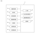
- FIG. 3 is a functional block diagram of the filter management device according to the present embodiment.
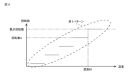
- FIG. 4 is a diagram showing an example of a pattern of the rotation speed control of the fan motor by the rotation speed control unit of FIG.
- FIG. 5 is a diagram showing another example of a pattern of the rotation speed control of the fan motor by the rotation speed control unit of FIG.
- FIG. 6 is a diagram showing an example of a threshold information management table stored in the storage unit of FIG.
- FIG. 7 is a supplementary diagram for explaining an example of the determination process by the determination unit in FIG.
- FIG. 8 is a supplementary diagram for explaining another example of the determination process by the determination unit in FIG.
- FIG. 9 is a diagram showing another example of the threshold information management table stored in the storage unit of FIG.
- Machine tool is a device that performs a predetermined process such as manufacturing a molded part, or joining a molded part to a supplied workpiece, machining, etc.
- the machine tool refers to various devices that generate oil mist during operation, such as a turning machine or a cutting machine.
- a machining room is a space that is partitioned from the outside by a cover that covers the entire machining tool.
- the machining room is one element that constitutes a machine tool.
- the machining room may be a room in which the machine tool is located.
- Concentration meter A device for measuring the oil mist concentration in a machining chamber.
- the concentration meter is an external device independent of the machine tool.
- the concentration meter may be an element constituting the machine tool.
- Mist collector A device for collecting oil mist in the machining chamber. In this embodiment, it is a filter type mist collector.
- the filter management device has the function of determining whether an abnormality has occurred in the filter installed in the mist collector or whether the filter needs to be replaced.
- the basic principle of this determination process is as follows. Filters with reduced filter performance, such as filters with an abnormality or filters that are clogged to the point of needing replacement, are collectively referred to as abnormal filters.
- the oil mist generation conditions under which oil mist is generated in the work chamber such as the concentration, amount, and timing of the oil mist generated in the work chamber
- the oil mist collection conditions under which oil mist is collected such as the amount of oil mist collected in the work chamber and the change over time in the collection amount
- the filter management device uses the basic principles of the above-mentioned judgment process to determine whether a filter abnormality has occurred or whether the filter needs to be replaced, on the premise that the rotation speed of the mist collector fan motor is controlled according to the oil mist concentration.
- the rotation speed refers to the number of rotations per unit time.
- a filter management device 2 is a device that functions as the core of a filter management system 1.
- the filter management system 1 has the filter management device 2, a machine tool 5, a concentration meter 6, and a mist collector 7.
- the machine tool 5 has a work room 52 and a control panel 55 that controls the entire machine tool 5.
- the control panel 55 has a function to set machining conditions and a function to control the operation of the machining tools in the work room 52 in accordance with the machining conditions.
- the control panel 55 also has a function to transmit data regarding the machining conditions to the filter management device 2 in response to a request to obtain machining conditions from the filter management device 2.
- the control panel 55 is realized by a numerical control device, a PC, or the like.
- the machining conditions here include conditions that can change the concentration, amount, timing, etc. of the oil mist generated in the work room when the machine tool 5 operates in accordance with the machining conditions. Examples of such conditions include machining time, machining speed, type of lubricant, and amount of lubricant supplied.
- the concentration meter 6 measures the oil mist concentration in the work chamber 52 and transmits concentration information indicating the oil mist concentration to the filter management device 2 .
- the mist collector 7 has a housing 72 installed outside the work chamber 52. The work chamber 52 and the housing 72 are connected by a duct 71. Inside the housing 72, a fan 75 for sucking the air in the work chamber 52 together with the oil mist, a filter 73 for recovering the oil mist from the air sucked by the fan 75, and a fan motor 77 for driving the fan 75 are arranged. Inside or outside the housing 72, a driver (not shown) for controlling the rotation speed of the fan motor 77 is arranged.
- the driver generates a drive current according to a command value of the rotation speed (referred to as a rotation speed command value) input from an input device (not shown) provided in the mist collector 7 or a filter management device 2 connected to the mist collector 7.
- the drive current generated by the driver is supplied to the fan motor 77.
- the fan motor 77 rotates at the rotation speed according to the command value.
- FIG. 2 is a hardware configuration diagram of the filter management device 2.
- the filter management device 2 is configured by connecting a RAM 12, a ROM 13, a storage device 14, a mist collector I/F 15, a concentration meter I/F 16, a machine tool I/F 17, an input device 18, a display device 19, a speaker 20, and a signal light 21 to a processor 11 via a data/control bus 10.
- the processor 11 is realized by a CPU, a GPU, etc.
- the RAM 12 functions as the main memory, work area, etc. of the processor 11.
- the ROM 13 stores the BIOS, OS, etc.
- the storage device 14 stores a filter management program. The various data stored in the storage device 14 may be recorded on removable media and distributed to users, or may be distributed by being downloaded to the filter management device 2 via a network.
- the mist collector 7 is connected to the mist collector I/F 15.
- a rotation speed command value for the fan motor 77 is input from the filter management device 2 to the mist collector 7 via the mist collector I/F 15.
- the concentration meter 6 is connected to the concentration meter I/F 16.
- Concentration information indicating the oil mist concentration is input from the concentration meter 6 to the filter management device 2 via the concentration meter I/F 16.
- the machine tool 5 is connected to the machine tool I/F 17.
- a request to obtain the machining conditions that are planned to be used or are currently being used is input from the filter management device 2 to the machine tool 5 via the machine tool I/F 17, and the machining conditions corresponding to the request are input from the machine tool 5 to the filter management device 2.
- the input device 18 is realized by a keyboard, a mouse, a jog, etc.
- a user can input various information to the filter management device 2 via the input device 18.
- the display device 19 is realized by an organic EL display, an LCD, etc.
- the display device 19 displays various screens according to the control of the processor 11.
- the speaker 20 generates sound to notify the user of a warning or alarm according to the control of the processor 11.
- the signal light 21 lights up to notify the user of a warning or alarm according to the control of the processor 11.
- FIG. 3 is a functional block diagram of the filter management device 2.
- the filter management device 2 When the filter management program loaded from the storage device 14 to the RAM 12 is executed by the processor 11, the filter management device 2 functions as an input unit 30, a processing condition receiving unit 31, a concentration information receiving unit 32, a storage unit 33, a screen creating unit 34, a display unit 35, a condition setting unit 36, a rotation speed control unit 37, a determination unit 38, a sound generating unit 39, and a signal generating unit 40.
- the input unit 30 is a function related to the input device 18 in FIG. 2, and inputs user operations to the filter management device 2.
- the machining condition receiving unit 31 receives machining conditions from the control panel 55 of the machine tool 5.
- the concentration information receiving unit 32 receives concentration information indicating the oil mist concentration from the concentration meter 6.
- the memory unit 33 is a function related to the storage device 14 in FIG. 2, and stores various information related to the processing of the filter management program. Specifically, the memory unit 33 stores data of a threshold information management table that summarizes threshold information. The threshold information management table will be described in detail later.
- the screen creation unit 34 displays various screens related to the filter management program. Specifically, the screen creation unit 34 creates a condition setting screen, a warning screen, and the like.
- the condition setting screen is configured to be able to set a pattern for controlling the rotation speed of the fan motor 77.
- the warning screen is created when the determination unit 38 determines that an abnormality has occurred in the filter 73 or that replacement of the filter 73 is necessary.
- the warning screen is configured to allow the user to recognize that an abnormality has occurred in the filter 73 or that replacement of the filter 73 is necessary.
- the warning screen may be configured to include a mark or text information indicating that an abnormality has occurred in the filter 73 or that replacement of the filter 73 is necessary, or the warning screen may be configured so that all or part of it is a warning color such as red or yellow.
- the display unit 35 is a function related to the display device 19 in FIG. 2, and displays the condition setting screen, warning screen, etc. created by the screen creation unit 34. In other words, the display unit 35 functions as a warning generation unit that generates a warning.
- the condition setting unit 36 sets a pattern for controlling the rotation speed of the fan motor 77 according to user operations on the condition setting screen.
- the rotation speed control unit 37 controls the fan motor 77 according to the rotation speed control pattern set by the user. Specifically, the rotation speed control unit 37 uses the set rotation speed control pattern to identify a rotation speed according to the oil mist concentration, and creates a rotation speed command value for rotating the fan motor 77 at the identified rotation speed. The rotation speed command value created by the rotation speed control unit 37 is sent to the mist collector 7.
- the determination unit 38 determines whether an abnormality has occurred in the filter 73 or whether replacement of the filter 73 is necessary based on the rotation speed of the fan motor 77. Details of the determination process by the determination unit 38 will be described later.
- the rotation speed of the fan motor 77 used in the determination process by the determination unit 38 is the rotation speed represented by a rotation speed command value generated by a rotation speed control unit 37 described later and transmitted to the mist collector 7, that is, the planned value of the rotation speed at which the fan motor 77 will rotate.
- the rotation speed of the fan motor 77 used in the determination process by the determination unit 38 may also be the rotation speed based on the output of an encoder (not shown) equipped on the fan motor 77, that is, the actual rotation speed of the fan motor 77.
- the sound generating unit 39 generates a predetermined sound (alarm sound) for notifying the user of an alarm when the determination unit 38 determines that an abnormality has occurred in the filter 73 or that replacement of the filter 73 is necessary.
- the sound generating unit 39 also generates a predetermined sound (warning sound) for notifying the user of a warning when the determination unit 38 determines that there is a sign of an abnormality occurring in the filter 73 or that the time to replace the filter 73 is approaching.
- the sound generating unit 39 functions as a warning generating unit that generates a warning.
- the signal generating unit 40 generates a first signal for turning on the signal light 21 in the first mode when the determining unit 38 determines that an abnormality has occurred in the filter 73 or that the filter 73 needs to be replaced.
- the signal generating unit 40 generates a second signal for turning on the signal light 21 in the second mode when the determining unit 38 determines that there is a sign of an abnormality occurring in the filter 73 or that the time to replace the filter 73 is approaching.
- the first signal turns on the signal light 21 in red
- the second signal turns on the signal light 21 in yellow.
- the first mode is different from the second mode, but may be the same as the second mode.
- the signal generating unit 40 functions as a warning generating unit that generates a warning.
- Figure 4 shows an example of a control pattern in which the rotation speed of the fan motor 77 is changed in stages in accordance with fluctuations in the oil mist concentration.
- the first pattern indicates that when the oil mist concentration is equal to or higher than concentration B1, the fan motor 77 rotates at the maximum rotation speed, and the rotation speed of the fan motor 77 is changed in five stages in accordance with fluctuations in the oil mist concentration until the rotation speed of the fan motor 77 reaches the maximum rotation speed.
- FIG. 5 shows an example of a control pattern for continuously changing the rotation speed of the fan motor 77 in accordance with the variation in the oil mist concentration.
- the second, third and fourth patterns indicate that the fan motor 77 rotates at the maximum rotation speed when the oil mist concentration is equal to or higher than concentration B1.
- the second pattern indicates that the rotation speed of the fan motor 77 increases linearly in accordance with the variation in the oil mist concentration until the rotation speed of the fan motor 77 reaches the maximum rotation speed.
- the third pattern indicates that the rotation speed of the fan motor 77 increases quadratically in accordance with the variation in the oil mist concentration until the rotation speed of the fan motor 77 reaches the maximum rotation speed.
- the fourth pattern indicates that while the oil mist concentration is low, the rotation speed of the fan motor 77 increases linearly little by little in accordance with the variation in the oil mist concentration, and when the oil mist concentration increases, the rotation speed of the fan motor 77 increases linearly and greatly in accordance with the variation in the oil mist concentration.
- the maximum rotation speed is not the maximum rotation speed in the specifications of the fan motor 77, but the maximum rotation speed controlled by the filter management device 2.
- the maximum rotation speed controlled by the filter management device 2 may also be the maximum rotation speed in the specifications of the fan motor 77.
- FIG. 6 is a diagram showing an example of the threshold management table stored in the memory unit 33.
- the processing conditions, the rotation speed control pattern, and the duration of the maximum rotation speed are associated with the management number.
- the duration of the maximum rotation speed is the time during which the state in which the rotation speed of the fan motor 77 indicates the maximum rotation speed continues, and is a threshold used in the judgment process of the judgment unit 38.
- the management number "001" indicates that the threshold value of the time during which the state in which the rotation speed of the fan motor 77 indicates the maximum rotation speed continues when the machine tool 5 operates according to the first processing conditions and the rotation speed of the fan motor 77 of the mist collector 7 is controlled according to the first pattern is T11.
- the threshold value is a threshold value for judging the occurrence of an abnormality in the filter 73 or the need to replace the filter 73.
- the threshold value T11 corresponds to the time during which the state in which the rotation speed of the fan motor 77 indicates the maximum rotation speed continues when the machine tool 5 operates according to the first machining condition, the rotation speed of the fan motor 77 of the mist collector 7 is controlled according to the first pattern, and an abnormal filter 73 is used as the filter 73 of the mist collector 7.
- the threshold value T11 may be a value actually measured using the abnormal filter 73, or may be a calculated value derived based on a simulation or the like.
- the conditions for generating oil mist in the machining chamber 52 such as the concentration, amount, and timing, change due to changes in the machining conditions, it is desirable to set a threshold value for each machining condition of the machine tool 5. If the recovery conditions, such as the amount and speed of oil mist collected, change due to changes in the pattern of control of the rotation speed of the fan motor 77, it is desirable to set a threshold value for each control pattern.
- FIG. 7 is a supplementary diagram for explaining an example of the determination process by the determination unit 38, and is a graph showing the change over time in the oil mist concentration measured by the concentration meter 6. Both of the two graphs 200, 300 show the change over time in the oil mist concentration when the first machining conditions are set for the machine tool 5 and the first pattern of rotation speed control is set for the fan motor 77. As shown in FIG. 4, the threshold value when the first machining conditions are set for the machine tool 5 and the first pattern is set for the fan motor 77 is T11.
- the determination unit 38 compares the duration Tm1 during which the rotation speed of the fan motor 77 remains at the maximum rotation speed in the first graph 200 with the threshold value T11. Because the duration Tm1 in the first graph 200 is less than the threshold value T11, the determination unit 38 determines that the filter 73 used in the mist collector 7 when the first graph 200 was obtained is a normal filter 73, and that no abnormality has occurred or that replacement of the filter 73 is not required.
- the determination unit 38 compares the duration Tm2 during which the rotation speed of the fan motor 77 in the second graph 300 remains at the maximum rotation speed with the threshold value T11. Because the duration Tm2 in the second graph 300 is equal to or greater than the threshold value T11, the determination unit 38 determines that an abnormality has occurred in the filter 73 used in the mist collector 7 when the second graph 300 was obtained, or that the filter 73 needs to be replaced.
- the filter management device 2 can determine whether an abnormality has occurred in the filter 73 or whether replacement of the filter 73 is necessary based on the rotation speed of the controlled fan motor 77.
- the user can be notified of this by an alarm sound, a signal light being turned on, or a warning screen being displayed.
- This allows the user to grasp the state of the filter 73, and can avoid situations in which a filter 73 with low oil mist collection efficiency is continued to be used for an extended period of time due to the inability to grasp the state of the filter 73 as in the past, or where the filter 73 is replaced even though the filter performance has not yet deteriorated.
- the user can replace the filter at a more appropriate time from the viewpoint of using up the filter 73.
- the above-mentioned determination process by the filter management device 2 according to this embodiment can be realized if the change over time in the oil mist concentration in the work chamber 52 and the rotation speed of the fan motor 77 of the mist collector 7 can be acquired, so there is no need to install new sensors, etc., and the introduction cost of the technology according to this embodiment can be said to be very low.
- the time during which the rotational speed of the fan motor 77 continues to indicate the maximum rotational speed is used as a judgment parameter for judging the occurrence of an abnormality in the filter 73 based on the rotational speed of the fan motor 77 or the need to replace the filter 73.
- This utilizes the fact that, if the generation conditions of the oil mist generated in the work chamber 52 and the collection conditions of the oil mist generated in the work chamber 52 are the same, the oil mist concentration in the work chamber 52 when a filter 73 having an abnormality is used in the mist collector 7 is less likely to decrease than the oil mist concentration in the work chamber 52 when a normal filter 73 is used in the mist collector 7.
- the judgment parameter is not limited to the time during which the rotational speed of the fan motor 77 continues to indicate the maximum rotational speed.
- it may be the time during which the rotation speed of the fan motor 77 continues to be equal to or greater than a predetermined rotation speed that is lower than the maximum rotation speed.
- FIG. 8 is a supplementary diagram for explaining another example of the judgment process by the judgment unit 38, and is a graph showing the change in oil mist concentration over time measured by the concentration meter 6.
- the first and second graphs 200 and 300 in FIG. 8 are the same graphs as FIG. 7.
- the judgment unit 38 calculates the gradient of the change in oil mist concentration over time, and when the calculated gradient is steeper than a threshold value, judges that an abnormality has occurred in the filter 73 or that the filter 73 needs to be replaced.
- the judgment unit 38 calculates gradients Gr2 and Gr3 for the first and second graphs 200 and 300, respectively, based on multiple measured values in which the oil mist concentration falls within the range from B2 to B1, and compares them with the threshold value. For example, if the gradient Gr2 is gentler than the threshold, the determination unit 38 determines that the filter 73 used in the mist collector 7 when the first graph 200 was acquired is a normal filter 73, and that no abnormality has occurred or that replacement of the filter 73 is not required. Similarly, if the gradient Gr3 is steeper than the threshold, the determination unit 38 determines that the filter 73 used in the mist collector 7 when the second graph 300 was acquired is abnormal or that replacement of the filter 73 is required.
- the range of the measured values used to calculate the gradient is not limited to the above.
- it may be a range in which the rotation speed of the fan motor 77 is equal to or greater than a predetermined rotation speed and the oil mist concentration reaches a maximum concentration.
- FIG. 9 is a diagram showing another example of a threshold management table stored in the memory unit 33.
- the processing conditions, the rotation speed control pattern, the first duration of the maximum rotation speed, and the second duration of the maximum rotation speed are associated with the management number.
- the first duration of the maximum rotation speed (first threshold value) is a threshold value for determining whether an abnormality has occurred in the filter 73 or whether it is necessary to replace the filter 73.
- the second duration of the maximum rotation speed is a threshold value for determining whether an abnormality has occurred in the filter 73 or whether it is near the time to replace the filter 73.
- the second threshold value may be obtained by actual measurement, like the first threshold value, or may be a calculated value derived by simulation or the like.
- the determination unit 38 compares the duration Tm1 during which the fan motor 77 continues to rotate at the maximum speed in the first graph 200 with the first threshold value T11 and the second threshold value T12. When the duration Tm1 in the first graph 200 is smaller than the first threshold value T11 and equal to or greater than the second threshold value T12, the determination unit 38 determines that there is a sign of an abnormality occurring in the filter 73 used in the mist collector 7 when the first graph 200 was acquired, or that the time to replace the filter 73 is approaching.
- the display unit 35 displays a screen to notify the user of this, and the sound generation unit 39 generates a sound different from that generated when the determination unit 38 determines that an abnormality has occurred in the filter 73 or that the filter 73 needs to be replaced.
- the condition of the filter 73 can be determined in more detail.
- the degree of clogging may also be displayed. This allows the user to grasp the condition of the filter 73 currently in use in more detail, and allows the user to prepare the filter 73 and plan a filter replacement schedule in advance. This contributes to improving the efficiency of the user's filter replacement work.
- the filter management device 2 comprises a receiving unit 32 that receives concentration information indicating the oil mist concentration from a concentration meter 6 that measures the oil mist concentration in the work chamber 52 of the machine tool 5, a rotation speed control unit 37 that controls the rotation speed of a fan motor 77 of a mist collector 7 that collects the oil mist in the work chamber 52 using a filter 73 based on the received concentration information, a determination unit 38 that determines whether an abnormality has occurred in the filter 73 or the need for replacement of the filter 73 based on the controlled rotation speed of the fan motor 77, and warning generating units 35, 39 that generate a warning when it is determined that an abnormality has occurred in the filter or that replacement of the filter 73 is necessary.
- the judgment unit 38 judges that there is a sign of an abnormality occurring in the filter 73 or that the time to replace the filter 73 is approaching when the gradient of the change in oil mist concentration over time is between a first threshold value and a second threshold value lower than the first threshold value.
- the predetermined rotation speed or more is the maximum rotation speed at which the rotation speed control unit 37 controls the fan motor 77.
- 1...filter management system 2...filter management device, 5...machine tool, 6...concentration meter, 7...mist collector, 10...data/control bus, 11...processor, 12...RAM, 13...ROM, 14...storage device, 15...mist collector I/F, 16...concentration meter I/F, 17...machine tool I/F, 18...input device, 19...display device, 20...speaker, 30...input section, 31...processing condition receiving section, 32...concentration information receiving section, 33...storage section, 34...screen creation section, 35...display section, 36...condition setting section, 37...rotation speed control section, 38...determination section, 39...sound generation section, 40...signal generation section, 52...machine room, 55...control panel, 71...duct, 72...housing, 73...filter, 75...fan, 77...fan motor.
Landscapes
- Engineering & Computer Science (AREA)
- Mechanical Engineering (AREA)
- Filtering Of Dispersed Particles In Gases (AREA)
Abstract
Description
本開示は、ミストコレクタのフィルタを管理するフィルタ管理装置に関する。 This disclosure relates to a filter management device that manages the filters of a mist collector.
工作機械を稼働させる際、ボールねじなどの機構部の摩擦低減、機械の気密、冷却、洗浄と様々な役割を果たす潤滑油が使用される。この潤滑油が飛散して微粒子となったものは一般的にオイルミストと呼ばれる。オイルミストは、人体に対して有害であり、作業性の低下や、電子機器の故障などを引き起こす。そのため、潤滑油が使用される空間に、当該空間に充満したオイルミストを除去するためのミストコレクタが知られている(例えば、特許文献1)。ミストコレクタによるオイルミストの除去方式として、様々な方式が知られている。例えば、ファンモータにより吸引したオイルミストを含む空気をフィルタでろ過することで、オイルミストを回収するフィルタ方式がある。フィルタ方式のミストコレクタでは、オイルミストの油分によってフィルタが目詰まりしてしまうと、吸引力が低下し、オイルミストの除去効果が低下してしまうため、オイルミストの除去効果が低下しないように、目詰まりが発生しているフィルタは交換しなければならない。しかしながら、フィルタの交換タイミングは明確ではないため、実際の現場では、まだ目詰まりが発生していないにも関わらずフィルタが交換されてしまい、また、既にフィルタの効果がほとんどないようなフィルタが継続して使用されている。 When machine tools are operated, lubricating oil is used to reduce friction in mechanical parts such as ball screws, and to seal, cool, and clean the machine. When this lubricating oil scatters and turns into fine particles, it is generally called oil mist. Oil mist is harmful to the human body and can cause workability problems and electronic device failures. For this reason, mist collectors are known for removing the oil mist that fills the space where the lubricating oil is used (for example, Patent Document 1). There are various methods for removing oil mist using mist collectors. For example, there is a filter method in which air containing oil mist sucked in by a fan motor is filtered through a filter to collect the oil mist. In a filter-type mist collector, if the filter becomes clogged with oil from the oil mist, the suction power decreases and the oil mist removal effect decreases, so a clogged filter must be replaced to prevent the oil mist removal effect from decreasing. However, because the timing for filter replacement is not clear, in actual practice, filters are replaced even when they are not yet clogged, and filters that already have little to no effect continue to be used.
ミストコレクタのフィルタの状態を把握することができる技術の提案が望まれている。 There is a need for technology that can grasp the condition of mist collector filters.
本開示に係るフィルタ管理装置は、工作機械の工作室内のオイルミスト濃度を測定する濃度計からオイルミスト濃度を表す濃度情報を受信する受信部と、受信された濃度情報に基づいて、工作室内のオイルミストをフィルタを用いて回収するミストコレクタのファンモータの回転数を制御する回転数制御部と、制御されたファンモータの回転数に基づいて、フィルタの異常発生又はフィルタの交換の必要性を判定する判定部と、フィルタの異常発生又はフィルタの交換が必要であると判定されたとき、ウォーニングを発生するウォーニング発生部と、具備する。 The filter management device according to the present disclosure comprises a receiving unit that receives concentration information indicating the oil mist concentration from a concentration meter that measures the oil mist concentration in the working chamber of the machine tool, a rotation speed control unit that controls the rotation speed of a fan motor of a mist collector that collects the oil mist in the working chamber using a filter based on the received concentration information, a determination unit that determines whether a filter abnormality has occurred or the need for filter replacement based on the controlled fan motor rotation speed, and a warning generation unit that generates a warning when it is determined that a filter abnormality has occurred or the filter needs replacing.
図面を参照しながら本実施形態に係るフィルタ管理装置を説明する。以下の説明において、略同一の機能及び構成を有する構成要素については、同一符号を付し、重複説明は必要な場合にのみ行う。 The filter management device according to this embodiment will be described with reference to the drawings. In the following description, components having substantially the same functions and configurations will be given the same reference numerals, and repeated explanations will be given only when necessary.
本実施形態において、用語を以下のように定義する。
工作機械:工作機械は、成形部品の作製、または、供給されるワークに対する成形部品の結合や機械加工などの所定の処理を行う装置である。特に、本実施形態において、工作機械は、旋削加工機、切削加工機などの動作時にオイルミストを発生する種々の装置を表す。
工作室:加工工具の全体を覆うカバーによって、外部空間に対して区画された空間である。典型的には、工作室は、工作機械を構成する一要素である。しかしながら、工作室は、工作機械が配置された部屋であってもよい。
濃度計:工作室内のオイルミスト濃度を測定する装置である。典型的には、濃度計は、工作機械に対して独立した外部装置である。しかしながら、濃度計は、工作機械を構成する一要素であってもよい。
ミストコレクタ:工作室内のオイルミストを回収する装置である。本実施形態では、フィルタ方式のミストコレクタであるものとする。
In this embodiment, the terms are defined as follows.
Machine tool: A machine tool is a device that performs a predetermined process such as manufacturing a molded part, or joining a molded part to a supplied workpiece, machining, etc. In particular, in this embodiment, the machine tool refers to various devices that generate oil mist during operation, such as a turning machine or a cutting machine.
A machining room is a space that is partitioned from the outside by a cover that covers the entire machining tool. Typically, the machining room is one element that constitutes a machine tool. However, the machining room may be a room in which the machine tool is located.
Concentration meter: A device for measuring the oil mist concentration in a machining chamber. Typically, the concentration meter is an external device independent of the machine tool. However, the concentration meter may be an element constituting the machine tool.
Mist collector: A device for collecting oil mist in the machining chamber. In this embodiment, it is a filter type mist collector.
本実施形態に係るフィルタ管理装置は、ミストコレクタに装備されたフィルタの異常発生又はフィルタの交換の必要性を判定する機能を有する。この判定処理の基本的な原理は以下の通りである。なお、異常が発生したフィルタや交換が必要なほど目詰まりしたフィルタ等のフィルタ性能が低下したフィルタをまとめて異常を有するフィルタと称する。 The filter management device according to this embodiment has the function of determining whether an abnormality has occurred in the filter installed in the mist collector or whether the filter needs to be replaced. The basic principle of this determination process is as follows. Filters with reduced filter performance, such as filters with an abnormality or filters that are clogged to the point of needing replacement, are collectively referred to as abnormal filters.
すなわち、工作室内に発生されるオイルミストの濃度、量、タイミング等のオイルミストが発生されるオイルミストの発生条件と、工作室内に発生されたオイルミストの回収量、回収量の時間変化等のオイルミストが回収されるオイルミストの回収条件とが同一である場合、ミストコレクタに正常なフィルタを使用したときの工作室内のオイルミスト濃度に比べて、ミストコレクタに異常を有するフィルタが使用されたときの工作室内のオイルミスト濃度は急峻に上昇し、上昇したオイルミスト濃度は下がりにくい。これは、正常なフィルタを使用したときに比べて、異常を有するフィルタを使用したときにミストコレクタに取り込むことのできる空気の量が減り、またフィルタによるオイルミストの回収効率(回収量)が低下するためである。したがって、正常なフィルタを使用したときのオイルミスト濃度の時間変化や、異常を有するフィルタを使用したときのオイルミスト濃度の時間変化が分かっていれば、現在測定中のオイルミスト濃度の時間変化から、ミストコレクタに使用されているフィルタの異常発生又はフィルタの交換の必要性を判定することができる。 In other words, if the oil mist generation conditions under which oil mist is generated in the work chamber, such as the concentration, amount, and timing of the oil mist generated in the work chamber, and the oil mist collection conditions under which oil mist is collected, such as the amount of oil mist collected in the work chamber and the change over time in the collection amount, are the same, the oil mist concentration in the work chamber when an abnormal filter is used in the mist collector will rise sharply and the increased oil mist concentration will be difficult to reduce, compared to the oil mist concentration in the work chamber when a normal filter is used in the mist collector. This is because the amount of air that can be taken into the mist collector is reduced when an abnormal filter is used, and the oil mist collection efficiency (amount collected) by the filter is reduced, compared to when a normal filter is used. Therefore, if the change over time in the oil mist concentration when a normal filter is used or the change over time in the oil mist concentration when an abnormal filter is used is known, it is possible to determine whether an abnormality has occurred in the filter used in the mist collector or the need to replace the filter from the change over time in the oil mist concentration currently being measured.
本実施形態に係るフィルタ管理装置は、オイルミスト濃度に従って、ミストコレクタのファンモータの回転数を制御することを前提に、上記の判定処理の基本的な原理を用いて、フィルタの異常発生又はフィルタの交換の必要性を判定する。なお、本実施形態において、回転数とは、単位時間あたりの回転数を表すものとする。 The filter management device according to this embodiment uses the basic principles of the above-mentioned judgment process to determine whether a filter abnormality has occurred or whether the filter needs to be replaced, on the premise that the rotation speed of the mist collector fan motor is controlled according to the oil mist concentration. Note that in this embodiment, the rotation speed refers to the number of rotations per unit time.
典型的には、本実施形態に係るフィルタ管理装置は以下のように構成される。
図1に示すように、本実施形態に係るフィルタ管理装置2は、フィルタ管理システム1の中枢として機能する装置である。フィルタ管理システム1は、フィルタ管理装置2と、工作機械5と、濃度計6と、ミストコレクタ7とを有する。
Typically, the filter management device according to this embodiment is configured as follows.
1 , a
工作機械5は、工作室52と、工作機械5の全体を制御する制御盤55と、を有する。具体的には、制御盤55は、加工条件を設定する機能と、加工条件に従って、工作室52内の加工工具の動作を制御する機能と、を有する。また、制御盤55は、フィルタ管理装置2から加工条件の取得要求に呼応して、加工条件に関するデータをフィルタ管理装置2に送信する機能も有する。制御盤55は、数値制御装置、PCなどにより実現される。ここでの、加工条件は、当該加工条件に従って工作機械5が動作したときに工作室内に発生するオイルミストの濃度、量、タイミング等を変化させ得る条件を含む。このような条件としては、例えば、加工時間、加工速度、潤滑油の種類、潤滑油の供給量などがあげられる。
The
濃度計6は、工作室52内のオイルミスト濃度を測定し、オイルミスト濃度を表す濃度情報をフィルタ管理装置2に送信する。
ミストコレクタ7は、工作室52の外部に設置される筐体72を有する。工作室52と筐体72との間は、ダクト71により連通する。筐体72の内部には、工作室52内の空気をオイルミストとともに吸引するためのファン75と、ファン75により吸引された空気からオイルミストを回収するフィルタ73と、ファン75を駆動するファンモータ77とが配置される。筐体72の内部又は筐体72の外部には、ファンモータ77の回転数を制御するドライバ(図示しない)が配置されている。ドライバは、ミストコレクタ7が備える入力装置(図示しない)又はミストコレクタ7に接続されたフィルタ管理装置2から入力された回転数の指令値(回転数指令値と称する)に応じた駆動電流を発生する。ドライバにより発生された駆動電流はファンモータ77に供給される。それにより、ファンモータ77は指令値通りの回転数で回転される。
The
The
図2は、フィルタ管理装置2のハードウェア構成図である。図2に示すように、フィルタ管理装置2は、プロセッサ11に対してデータ/制御バス10を介して、RAM12、ROM13、記憶装置14、ミストコレクタI/F15、濃度計I/F16、工作機械I/F17,入力装置18、表示装置19、スピーカ20、信号灯21が接続されて構成されている。
FIG. 2 is a hardware configuration diagram of the
プロセッサ11は、CPU、GPUなどにより実現される。RAM12は、プロセッサ11の主メモリ、ワークエリア等として機能する。ROM13には、BIOS,OSなどが記憶されている。記憶装置14には、フィルタ管理プログラムが記憶されている。記憶装置14に記憶されている各種データは、リムーバブルメディアに記録されてユーザに配布されてもよいし、ネットワークを介してフィルタ管理装置2にダウンロードされることにより配布されてもよい。
The
ミストコレクタI/F15にはミストコレクタ7が接続されている。ミストコレクタI/F15を介して、フィルタ管理装置2からミストコレクタ7にファンモータ77の回転数指令値が入力される。濃度計I/F16には、濃度計6が接続されている。濃度計I/F16を介して、濃度計6からフィルタ管理装置2にオイルミスト濃度を表す濃度情報が入力される。工作機械I/F17には工作機械5が接続されている。工作機械I/F17を介して、フィルタ管理装置2から工作機械5に、使用予定又は使用中の加工条件の取得要求が入力され、工作機械5からフィルタ管理装置2に、取得要求に呼応した加工条件が入力される。
The
入力装置18は、キーボード、マウス、ジョグ等により実現される。ユーザは、入力装置18を介して、フィルタ管理装置2に対して各種情報を入力することができる。表示装置19は、有機ELディスプレイ、LCD等により実現される。表示装置19は、プロセッサ11の制御に従って、各種画面を表示する。スピーカ20は、プロセッサ11の制御に従って、ウォーニング又はアラームをユーザに通知するための音声を発生する。信号灯21は、プロセッサ11の制御に従って、ウォーニング又はアラームをユーザに通知するために点灯する。
The
図3は、フィルタ管理装置2の機能ブロック図である。記憶装置14からRAM12にロードされたフィルタ管理プログラムがプロセッサ11により実行されることで、フィルタ管理装置2は、入力部30、加工条件受信部31、濃度情報受信部32、記憶部33、画面作成部34、表示部35、条件設定部36、回転数制御部37、判定部38、音声発生部39、信号発生部40として機能する。
FIG. 3 is a functional block diagram of the
入力部30は、図2の入力装置18に係る機能であり、フィルタ管理装置2に対してユーザ操作を入力する。加工条件受信部31は、工作機械5の制御盤55から加工条件を受信する。濃度情報受信部32は、濃度計6からオイルミスト濃度を表す濃度情報を受信する。記憶部33は、図2の記憶装置14に係る機能であり、フィルタ管理プログラムの処理に係る各種情報を記憶する。具体的には、記憶部33は、閾値情報をまとめた閾値情報管理テーブルのデータを記憶する。閾値情報管理テーブルの詳細は後述する。
The
画面作成部34は、フィルタ管理プログラムに係る各種画面を表示する。具体的には、画面作成部34は、条件設定画面、ウォーニング画面等を作成する。例えば、条件設定画面は、ファンモータ77の回転数制御のパターンを設定可能に構成される。ウォーニング画面は、フィルタ73に異常が発生したこと、又はフィルタ73の交換が必要であることが判定部38により判定されたことを契機に作成される。ウォーニング画面は、フィルタ73に異常が発生したこと、又はフィルタ73の交換が必要であることをユーザに認識させることができるように構成される。例えば、ウォーニング画面は、フィルタ73に異常が発生したこと、又はフィルタ73の交換が必要であることを表すマーク、テキスト情報が含まれるように構成されてもよいし、ウォーニング画面の全体又は一部が、赤色、黄色などの警告色となるように構成されてもよい。
The
表示部35は、図2の表示装置19に係る機能であり、画面作成部34により作成された条件設定画面、ウォーニング画面等を表示する。つまり、表示部35は、ウォーニングを発生するウォーニング発生部として機能する。
The
条件設定部36は、条件設定画面上のユーザ操作に従って、ファンモータ77の回転数制御のパターンを設定する。回転数制御部37は、ユーザにより設定された回転数制御のパターンに従って、ファンモータ77を制御する。具体的には、回転数制御部37は、設定された回転数制御パターンを用いて、オイルミスト濃度に応じた回転数を特定し、特定した回転数でファンモータ77を回転させるための回転数指令値を作成する。回転数制御部37により作成された回転数指令値はミストコレクタ7に送出される。
The
判定部38は、ファンモータ77の回転数に基づいて、フィルタ73の異常発生又はフィルタ73の交換の必要性を判定する。判定部38による判定処理の詳細は後述する。なお、判定部38による判定処理に用いられるファンモータ77の回転数とは、後述の回転数制御部37により発生され、ミストコレクタ7に送信される回転数指令値が表す回転数、つまりファンモータ77が回転される回転数の予定値である。しかしながら、判定部38による判定処理に用いられるファンモータ77の回転数は、ファンモータ77に装備されたエンコーダ(図示しない)の出力に基づく回転数、つまりファンモータ77の実際の回転数であってもよい。
The
音声発生部39は、フィルタ73に異常が発生したこと、又はフィルタ73の交換が必要であることが判定部38により判定されたことを契機に、アラームをユーザに通知するための所定の音声(アラーム音)を発生する。また、音声発生部39は、フィルタ73に異常が発生する予兆がある又はフィルタ73の交換時期が近いことが判定部38により判定されたことを契機に、ウォーニングをユーザに通知するための所定の音声(警告音)を発生する。つまり、音声発生部39は、ウォーニングを発生するウォーニング発生部として機能する。
信号発生部40は、フィルタ73に異常が発生したこと、又はフィルタ73の交換が必要であることが判定部38により判定されたことを契機に、信号灯21を第1態様で点灯させるための第1信号を発生する。また、信号発生部40は、フィルタ73に異常が発生する予兆がある又はフィルタ73の交換時期が近いことが判定部38により判定されたことを契機に、信号灯21を第2態様で点灯させるための第2信号を発生する。例えば、第1信号により、信号灯21は赤色に点灯され、第2信号により、信号灯21は黄色に点灯される。典型的には、第1態様は、第2態様と異なるが、第2態様と同一であってもよい。信号発生部40は、ウォーニングを発生するウォーニング発生部として機能する。
The
The
以下、図4、図5を参照して、回転数制御部37によるファンモータ77の回転数制御のバリエーションを説明する。
Below, variations in the control of the rotation speed of the
図4は、オイルミスト濃度の変動に従ってファンモータ77の回転数を段階的に変化させる制御パターンの一例を示している。図4に示すように、第1パターンは、オイルミスト濃度が濃度B1以上であるときにファンモータ77が最大回転数で回転され、ファンモータ77の回転数が最大回転数に到達するまで、オイルミスト濃度の変動に従って、ファンモータ77の回転数が5段階で変化されることを表している。
Figure 4 shows an example of a control pattern in which the rotation speed of the
図5は、オイルミスト濃度の変動に従ってファンモータ77の回転数を連続的に変化させる制御パターンの一例を示している。図5に示すように、第2,第3、第4パターンは、オイルミスト濃度が濃度B1以上であるときに、ファンモータ77が最大回転数で回転されることを表している。第2パターンは、ファンモータ77の回転数が最大回転数に到達するまで、オイルミスト濃度の変動に従って、ファンモータ77の回転数が線形的に増加することを表している。第3パターンは、ファンモータ77の回転数が最大回転数に到達するまで、オイルミスト濃度の変動に従って、ファンモータ77の回転数が二次曲線的に増加することを表している。第4パターンは、オイルミスト濃度が低い間は、オイルミスト濃度の変動に従って、ファンモータ77の回転数が線形的に少しずつ増加し、オイルミスト濃度が高くなると、オイルミスト濃度の変動に従って、ファンモータ77の回転数が線形的に多く増加することを表している。
FIG. 5 shows an example of a control pattern for continuously changing the rotation speed of the
なお、最大回転数は、ファンモータ77の仕様上の最大回転数ではなく、フィルタ管理装置2による制御上の最大回転数である。もちろん、フィルタ管理装置2による制御上の最大回転数が、ファンモータ77の仕様上の最大回転数であってもよい。
Note that the maximum rotation speed is not the maximum rotation speed in the specifications of the
以下、図6を参照して、記憶部33に記憶されている閾値管理テーブルを説明する。図6は、記憶部33に記憶されている閾値管理テーブルの一例を示す図である。図6に示すように、閾値管理テーブルでは、管理番号に対して、加工条件、回転数制御のパターン、最大回転数の継続時間が関連付けられている。最大回転数の継続時間は、ファンモータ77の回転数が最大回転数を示す状態が継続する時間であり、判定部38の判定処理に用いられる閾値である。例えば、管理番号“001”は、工作機械5が第1加工条件に従って動作し、ミストコレクタ7のファンモータ77の回転数が第1パターンに従って制御されているときの、ファンモータ77の回転数が最大回転数を示す状態が継続する時間の閾値がT11であることを表している。閾値は、フィルタ73の異常発生又はフィルタ73の交換の必要性を判定する閾値である。したがって、閾値T11は、工作機械5が第1加工条件に従って動作し、ミストコレクタ7のファンモータ77の回転数が第1パターンに従って制御され、ミストコレクタ7のフィルタ73として異常を有するフィルタ73が使用されたときの、ファンモータ77の回転数が最大回転数を示す状態が継続する時間に対応する。閾値T11は、異常を有するフィルタ73を用いて実際に測定された値であってもよいし、シミュレーション等に基づいて導き出された計算値であってもよい。
Below, the threshold management table stored in the
なお、加工条件が変化したことで、工作室52内に発生するオイルミストの濃度、量、タイミング等の発生条件が変化してしまうのであれば、閾値は工作機械5の加工条件ごとに設けられていることが望ましい。また、ファンモータ77の回転数制御のパターンが変化したことで、オイルミストの回収量、回収速度などの回収条件が変動するのであれば、閾値は制御パターンごとに設けられていることが望ましい。これらは、工作室52内に発生するオイルミストの発生条件とミストコレクタ7によるオイルミストの回収条件とのうち一方が異なれば、オイルミスト濃度の時間変化は変動してしまう、つまり、ファンモータ77の回転数が最大回転数を示す状態が継続する時間がフィルタ73の状態の変動以外の要因で変化してしまうからである。
If the conditions for generating oil mist in the
一方で、ミストコレクタ7のファンモータ77の回転数を制御できないのであれば、制御パターンごとに閾値を設ける必要はない。同様に、加工条件によって工作室52内に発生するオイルミストの濃度、量、タイミング等の変化がないのであれば、又は、工作機械5が常に同じ加工条件に従って動作しているのであれば、加工条件ごとに閾値を設ける必要はない。
On the other hand, if the rotation speed of the
以下、図7を参照して判定部38による判定処理の詳細を説明する。図7は、判定部38による判定処理の一例を説明するための補足図であって、濃度計6により測定されたオイルミスト濃度の時間変化を表すグラフである。2つのグラフ200,300は、いずれも、工作機械5に対して第1加工条件が設定され、ファンモータ77に対して回転数制御の第1パターンが設定されているときの、オイルミスト濃度の時間変化を表す。図4に示すように、工作機械5に対して第1加工条件が設定され、ファンモータ77に対して第1パターンが設定されている場合の閾値はT11である。
The determination process by the
判定部38は、第1グラフ200における、ファンモータ77の回転数が最大回転数を示す状態が継続する継続時間Tm1を、閾値T11に対して比較する。第1グラフ200における継続時間Tm1は、閾値T11よりも小さいため、判定部38は、第1グラフ200が取得されたときにミストコレクタ7に使用されていたフィルタ73は正常なフィルタ73であって、異常が発生していない又はフィルタ73の交換が必要ではないと判定する。
The
同様に、判定部38は、第2グラフ300における、ファンモータ77の回転数が最大回転数を示す状態が継続する継続時間Tm2を、閾値T11に対して比較する。第2グラフ300における継続時間Tm2は、閾値T11以上であるため、判定部38は、第2グラフ300が取得されたときにミストコレクタ7に使用されていたフィルタ73は異常が発生している、又はフィルタ73は交換の必要があると判定する。
Similarly, the
以上説明したように、本実施形態に係るフィルタ管理装置2によれば、制御されたファンモータ77の回転数に基づいて、フィルタ73の異常発生又はフィルタ73の交換の必要性を判定することができ、フィルタ73の異常発生又は前記フィルタ73の交換が必要であると判定されたときには、その旨をアラーム音や、信号灯の点灯、ウォーニング画面の表示によりユーザに報知することができる。それにより、ユーザは、フィルタ73の状態を把握することができ、従来のようにフィルタ73の状態を把握できなかったために、オイルミストの回収効率の低いフィルタ73をいつまでも使用し続けられてしまう事態や、まだフィルタ性能が低下していないにもかかわらずフィルタ73が交換されてしまう事態を回避することができる。つまり、ユーザは、フィルタ73を使い切るという観点では、より適切な時期にフィルタ交換を行うことができる。
As described above, the
本実施形態に係るフィルタ管理装置2による上記の判定処理は、工作室52内のオイルミスト濃度の時間変化とミストコレクタ7のファンモータ77の回転数とを取得できれば実現可能であるため、新たなセンサ等を設ける必要はなく、本実施形態に係る技術の導入コストは非常に安いといえる。
The above-mentioned determination process by the
本実施形態では、ファンモータ77の回転数に基づくフィルタ73の異常発生又はフィルタ73の交換の必要性を判定するための判定パラメータとして、ファンモータ77の回転数が最大回転数を示す状態が継続する時間を用いた。これは、工作室52内に発生されるオイルミストの発生条件と、工作室52内に発生されたオイルミストの回収条件とが同じであれば、ミストコレクタ7に異常を有するフィルタ73が使用されたときの工作室52内のオイルミスト濃度が、ミストコレクタ7に正常なフィルタ73を使用したときの工作室52内のオイルミスト濃度に比べて、オイルミスト濃度が下がりにくいことを利用したものである。したがって、判定パラメータとして、ファンモータ77の回転数が最大回転数を示す状態が継続する時間を採用することは、正常なフィルタ73を使用した場合と異常を有するフィルタ73を使用した場合とで、明確な差異を生じさせることができるため、判定の精度を向上させることができる。もちろん、判定パラメータは、ファンモータ77の回転数が最大回転数を示す状態が継続する時間に限定されない。例えば、ファンモータ77の回転数が最大回転数よりも回転数が少ない所定回転数以上を示す状態が継続する時間であってもよい。
In this embodiment, the time during which the rotational speed of the
また、判定パラメータとして、オイルミスト濃度の時間変化の勾配を採用してもよい。図8は、判定部38による判定処理の他の例を説明するための補足図であって、濃度計6により測定されたオイルミスト濃度の時間変化を表すグラフである。図8の第1、第2グラフ200,300は図7と同一のグラフである。判定部38は、オイルミスト濃度の時間変化の勾配を計算し、計算した勾配が閾値より急峻であるときに、フィルタ73の異常発生又は前記フィルタ73の交換が必要であると判定する。例えば、判定部38は、第1、第2グラフ200、300について、オイルミスト濃度がB2からB1までの範囲に含まれる複数の測定値に基づいて、勾配Gr2、Gr3をそれぞれ計算し、閾値に対して比較する。例えば、勾配Gr2が閾値よりも緩やかな勾配である場合、判定部38は、第1グラフ200が取得されたときにミストコレクタ7に使用されていたフィルタ73は正常なフィルタ73であって、異常が発生していない又はフィルタ73の交換が必要ではないと判定する。同様に、勾配Gr3が閾値よりも急峻である場合、判定部38は、第2グラフ300が取得されたときにミストコレクタ7に使用されていたフィルタ73は、異常が発生している、又はフィルタ73は交換の必要があると判定する。なお、勾配の計算に用いる測定値の範囲は、上記に限定されない。例えば、ファンモータ77の回転数が所定回転数以上であって、オイルミスト濃度が最大濃度に到達するまでの範囲であってもよい。
The gradient of the change in oil mist concentration over time may also be used as the judgment parameter. FIG. 8 is a supplementary diagram for explaining another example of the judgment process by the
これは、工作室52内に発生されるオイルミストの発生条件と、工作室52内に発生されたオイルミストの回収条件とが同じであれば、ミストコレクタ7に異常を有するフィルタ73が使用されたときの工作室52内のオイルミスト濃度が、ミストコレクタ7に正常なフィルタ73を使用したときの工作室52内のオイルミスト濃度に比べて、オイルミスト濃度が急峻に立ち上がることを利用したものである。したがって、判定パラメータとして、オイルミスト濃度の時間変化の勾配を採用することは、正常なフィルタ73を使用した場合と異常を有するフィルタ73を使用した場合とで、明確な差異を生じさせるため、判定パラメータとして、ファンモータ77の回転数が最大回転数を示す状態が継続する時間を採用した場合と同様に、判定の精度を向上させることができる。
This takes advantage of the fact that, if the conditions for generating oil mist in the
本実施形態では、判定部38の判定処理に用いられる閾値は1つであったが、複数の閾値が判定部38の判定処理に用いられてもよい。図9は、記憶部33に記憶されている閾値管理テーブルの他の例を示す図である。図9に示すように、閾値管理テーブル400では、管理番号に対して、加工条件、回転数制御のパターン、最大回転数の第1継続時間、及び最大回転数の第2継続時間が関連付けられている。最大回転数の第1継続時間(第1閾値)は、フィルタ73の異常発生又はフィルタ73の交換の必要性を判定する閾値である。最大回転数の第2継続時間(第2閾値)は、フィルタ73に異常が発生する予兆又はフィルタ73の交換時期が近いことを判定する閾値である。第2閾値は、第1閾値と同様に、実際の測定により取得されてもよいし、シミュレーション等により導き出された計算値であってもよい。
In this embodiment, one threshold value is used in the judgment process of the
例えば、図7に示すように、判定部38は、第1グラフ200における、ファンモータ77の回転数が最大回転数を示す状態が継続する継続時間Tm1を、第1閾値T11、第2閾値T12に対してそれぞれ比較する。第1グラフ200における継続時間Tm1が、第1閾値T11よりも小さく、第2閾値T12以上であるとき、判定部38は、第1グラフ200が取得されたときにミストコレクタ7に使用されていたフィルタ73に異常が発生する予兆がある又はフィルタ73の交換時期が近いことを判定する。判定部38により、フィルタ73に異常が発生する予兆がある又はフィルタ73の交換時期が近いことが判定されたことを契機に、表示部35はその旨をユーザに報知するための画面を表示し、音声発生部39は、判定部38により、フィルタ73に異常発生又はフィルタ73の交換が必要であることを判定されたときとは異なる音声を発生する。
7, for example, the
このように、フィルタ73の目詰まり度合い等のフィルタ73の状態が異なる複数の閾値を設けることで、フィルタ73の状態をより詳細に判定することができる。なお、目詰まり度合いを表示するようにしてもよい。それにより、ユーザは、現在使用中のフィルタ73の状態をより詳細に把握することができ、フィルタ73の準備や、フィルタ交換のスケジュールの計画を事前に実施することができる。これは、ユーザによるフィルタ交換に係る作業効率を向上に寄与する。
In this way, by providing multiple thresholds representing
本実施形態および変形例に関し、更に以下の付記を開示する。
(付記1)
フィルタ管理装置2は、工作機械5の工作室52内のオイルミスト濃度を測定する濃度計6からオイルミスト濃度を表す濃度情報を受信する受信部32と、受信された濃度情報に基づいて、工作室52内のオイルミストをフィルタ73を用いて回収するミストコレクタ7のファンモータ77の回転数を制御する回転数制御部37と、制御されたファンモータ77の回転数に基づいて、フィルタ73の異常発生又はフィルタ73の交換の必要性を判定する判定部38と、フィルタの異常発生又はフィルタ73の交換が必要であると判定されたとき、ウォーニングを発生するウォーニング発生部35,39と、を具備する。
(付記2)
付記1に記載のフィルタ管理装置2において、回転数制御部37は、オイルミスト濃度の変動に従ってファンモータ77の回転数を段階的に変化させる。
(付記3)
付記1に記載のフィルタ管理装置2において、回転数制御部37は、オイルミスト濃度の変動に従ってファンモータ77の回転数を連続的に変化させる。
(付記4)
付記1乃至3のいずれかに記載のフィルタ管理装置2において、判定部38は、ファンモータ77の回転数が所定回転数以上を示す状態が継続する時間が第1の閾値に達したとき、フィルタ73の異常発生又はフィルタ73の交換が必要であると判定する。
(付記5)
付記4に記載のフィルタ管理装置2において、判定部38は、ファンモータ77の回転数が所定回転数以上を示す状態が継続する時間が第1の閾値より短い第2の閾値に達したとき、フィルタ73に異常が発生する予兆又はフィルタ73の交換時期が近いことを判定する。
(付記6)
付記1乃至3のいずれかに記載のフィルタ管理装置2において、判定部38は、オイルミスト濃度の時間変化の勾配が第1閾値より急峻であるときフィルタ73の異常発生又はフィルタ73の交換が必要であると判定する。
(付記7)
付記6に記載のフィルタ管理装置2において、判定部38は、オイルミスト濃度の時間変化の勾配が第1閾値と第1閾値より低い第2閾値との間であるとき、フィルタ73に異常が発生する予兆又はフィルタ73の交換時期が近いことを判定する。
(付記8)
付記4乃至7のいずれかに記載のフィルタ管理装置2において、所定回転数以上は、回転数制御部37がファンモータ77を制御する最大回転数である。
The following supplementary notes are further disclosed regarding this embodiment and the modified examples.
(Appendix 1)
The
(Appendix 2)
In the
(Appendix 3)
In the
(Appendix 4)
In the
(Appendix 5)
In the
(Appendix 6)
In the
(Appendix 7)
In the
(Appendix 8)
In the
本開示の実施形態について詳述したが、本開示は上述した個々の実施形態に限定されるものではない。これらの実施形態は、発明の要旨を逸脱しない範囲で、または、特許請求の範囲に記載された内容とその均等物から導き出される本発明の思想および趣旨を逸脱しない範囲で、種々の追加、置き換え、変更、部分的削除等が可能である。例えば、上述した実施形態において、各動作の順序や各処理の順序は、一例として示したものであり、これらに限定されるものではない。また、上述した実施形態の説明に数値又は数式が用いられている場合も同様である。 Although the embodiments of the present disclosure have been described in detail, the present disclosure is not limited to the individual embodiments described above. Various additions, substitutions, modifications, partial deletions, etc. are possible in these embodiments, without departing from the gist of the invention, or without departing from the idea and intent of the present invention derived from the contents described in the claims and their equivalents. For example, in the above-mentioned embodiments, the order of each operation and the order of each process are shown as examples, and are not limited to these. The same applies when numerical values or formulas are used in the explanation of the above-mentioned embodiments.
1…フィルタ管理システム、2…フィルタ管理装置、5…工作機械、6…濃度計、7…ミストコレクタ、10…データ/制御バス、11…プロセッサ、12…RAM、13…ROM、14…記憶装置、15…ミストコレクI/F、16…濃度計I/F、17…工作機械I/F、18…入力装置、19…表示装置、20…スピーカ、30…入力部、31…加工条件受信部、32…濃度情報受信部、33…記憶部、34…画面作成部、35…表示部、36…条件設定部、37…回転数制御部、38…判定部、39…音声発生部、40…信号発生部、52…工作室、55…制御盤、71…ダクト、72…筐体、73…フィルタ、75…ファン、77…ファンモータ。 1...filter management system, 2...filter management device, 5...machine tool, 6...concentration meter, 7...mist collector, 10...data/control bus, 11...processor, 12...RAM, 13...ROM, 14...storage device, 15...mist collector I/F, 16...concentration meter I/F, 17...machine tool I/F, 18...input device, 19...display device, 20...speaker, 30...input section, 31...processing condition receiving section, 32...concentration information receiving section, 33...storage section, 34...screen creation section, 35...display section, 36...condition setting section, 37...rotation speed control section, 38...determination section, 39...sound generation section, 40...signal generation section, 52...machine room, 55...control panel, 71...duct, 72...housing, 73...filter, 75...fan, 77...fan motor.
Claims (8)
前記受信された濃度情報に基づいて、前記工作室内のオイルミストをフィルタを用いて回収するミストコレクタのファンモータの回転数を制御する回転数制御部と、
前記制御されたファンモータの回転数に基づいて、前記フィルタの異常発生又は前記フィルタの交換の必要性を判定する判定部と、
前記フィルタの異常発生又は前記フィルタの交換が必要であると判定されたとき、ウォーニングを発生するウォーニング発生部と、
を具備するフィルタ管理装置。 a receiving unit that receives concentration information indicating an oil mist concentration from a concentration meter that measures an oil mist concentration in a working chamber of the machine tool;
a rotation speed control unit that controls the rotation speed of a fan motor of a mist collector that collects the oil mist in the working chamber using a filter based on the received concentration information;
a determination unit that determines whether an abnormality has occurred in the filter or whether replacement of the filter is necessary based on the controlled rotation speed of the fan motor;
a warning generating unit that generates a warning when it is determined that an abnormality has occurred in the filter or that replacement of the filter is necessary;
A filter management device comprising:
請求項1記載のフィルタ管理装置。 The rotation speed control unit changes the rotation speed of the fan motor in a stepwise manner in accordance with the fluctuation of the oil mist concentration.
The filter management device of claim 1.
請求項1記載のフィルタ管理装置。 The filter management device according to claim 1 , wherein the rotation speed control unit continuously changes the rotation speed of the fan motor in accordance with fluctuations in the oil mist concentration.
請求項1乃至3のいずれか一項に記載のフィルタ管理装置。 the determination unit determines that an abnormality has occurred in the filter or that replacement of the filter is necessary when a time during which a state in which the rotation speed of the fan motor is equal to or greater than a predetermined rotation speed continues to reach a first threshold value.
A filter management device according to any one of claims 1 to 3.
請求項4記載のフィルタ管理装置。 the determination unit determines that there is a sign of an abnormality occurring in the filter or that the time to replace the filter is approaching when a duration during which the rotation speed of the fan motor continues to be equal to or greater than a predetermined rotation speed reaches a second threshold value that is shorter than the first threshold value.
5. The filter management device of claim 4.
請求項1乃至3のいずれか一項に記載のフィルタ管理装置。 The determination unit determines that an abnormality has occurred in the filter or that replacement of the filter is necessary when a gradient of a time change in the oil mist concentration is steeper than a first threshold value.
A filter management device according to any one of claims 1 to 3.
請求項7に記載のフィルタ管理装置。
The filter management device according to claim 7, wherein the determination unit determines that there is a sign of an abnormality occurring in the filter or that the time to replace the filter is approaching when a gradient of the change in the oil mist concentration over time is between the first threshold value and a second threshold value lower than the first threshold value.
Priority Applications (1)
| Application Number | Priority Date | Filing Date | Title |
|---|---|---|---|
| PCT/JP2023/030159 WO2025041266A1 (en) | 2023-08-22 | 2023-08-22 | Filter management device |
Applications Claiming Priority (1)
| Application Number | Priority Date | Filing Date | Title |
|---|---|---|---|
| PCT/JP2023/030159 WO2025041266A1 (en) | 2023-08-22 | 2023-08-22 | Filter management device |
Publications (1)
| Publication Number | Publication Date |
|---|---|
| WO2025041266A1 true WO2025041266A1 (en) | 2025-02-27 |
Family
ID=94731535
Family Applications (1)
| Application Number | Title | Priority Date | Filing Date |
|---|---|---|---|
| PCT/JP2023/030159 Pending WO2025041266A1 (en) | 2023-08-22 | 2023-08-22 | Filter management device |
Country Status (1)
| Country | Link |
|---|---|
| WO (1) | WO2025041266A1 (en) |
Citations (3)
| Publication number | Priority date | Publication date | Assignee | Title |
|---|---|---|---|---|
| JP2020078765A (en) * | 2018-11-12 | 2020-05-28 | 株式会社コガネイ | Dust collector |
| WO2020196274A1 (en) * | 2019-03-28 | 2020-10-01 | パナソニックIpマネジメント株式会社 | Ventilator |
| WO2022259671A1 (en) * | 2021-06-09 | 2022-12-15 | Dmg森精機株式会社 | Machine tool, control method, and control program |
-
2023
- 2023-08-22 WO PCT/JP2023/030159 patent/WO2025041266A1/en active Pending
Patent Citations (3)
| Publication number | Priority date | Publication date | Assignee | Title |
|---|---|---|---|---|
| JP2020078765A (en) * | 2018-11-12 | 2020-05-28 | 株式会社コガネイ | Dust collector |
| WO2020196274A1 (en) * | 2019-03-28 | 2020-10-01 | パナソニックIpマネジメント株式会社 | Ventilator |
| WO2022259671A1 (en) * | 2021-06-09 | 2022-12-15 | Dmg森精機株式会社 | Machine tool, control method, and control program |
Similar Documents
| Publication | Publication Date | Title |
|---|---|---|
| CN109799784B (en) | Tool wear detection device, detection method thereof and tool wear compensation method | |
| CN114555292B (en) | Working state monitoring method and system for working machine | |
| CN102441817B (en) | Duty history management method and duty history management devices | |
| JP4625845B2 (en) | System and method for detecting abnormal conditions associated with a reactor | |
| KR101999112B1 (en) | Tool life maintenance system and tool life maintenance method for machine tools | |
| JP6797528B2 (en) | Monitoring device and monitoring method | |
| CN112783586B (en) | Customizable workflow for machine management | |
| CN106181581A (en) | The vibration information display device of lathe | |
| US7571022B2 (en) | System and method for monitoring machine health | |
| CN102637017A (en) | Real-time monitoring device and method for spindle performance and calibrating experimental device and method thereof | |
| CN110275488B (en) | Information processing apparatus, system, information processing method, and recording medium | |
| JP7185247B2 (en) | Machine diagnostic system and diagnostic program | |
| EP2740337B1 (en) | Method and device for detecting clogging of a filter | |
| JP7316498B2 (en) | Diagnostic system, diagnostic method, program and recording medium | |
| CN108536095A (en) | A kind of leading screw wear extent real-time predicting method | |
| CN104668974B (en) | PLC (Programmable Logic Controller) hydraulic station-based pressure/flow rate closed-loop control method | |
| JP5461136B2 (en) | Plant diagnostic method and diagnostic apparatus | |
| JP7740864B2 (en) | Anomaly detection device, anomaly detection server, and anomaly detection method | |
| JP7310195B2 (en) | Diagnostic device, diagnostic system and diagnostic program | |
| JP2018156486A (en) | Information providing system, information providing method, and program | |
| CN118647951A (en) | Diagnostic device and computer-readable recording medium | |
| CN106125667A (en) | Digital control processing online monitoring system and method | |
| JP6526583B2 (en) | Cutting machine monitoring device | |
| JP2018073328A (en) | Diagnosis system and diagnosis program for machine | |
| KR102901092B1 (en) | Apparatus and Method for status diagnosis of machine tools |
Legal Events
| Date | Code | Title | Description |
|---|---|---|---|
| 121 | Ep: the epo has been informed by wipo that ep was designated in this application |
Ref document number: 23949727 Country of ref document: EP Kind code of ref document: A1 |
|
| ENP | Entry into the national phase |
Ref document number: 2025541218 Country of ref document: JP Kind code of ref document: A |
|
| WWE | Wipo information: entry into national phase |
Ref document number: 2025541218 Country of ref document: JP |
|
| NENP | Non-entry into the national phase |
Ref country code: DE |