WO2025041261A1 - Adaptateur de conversion - Google Patents
Adaptateur de conversion Download PDFInfo
- Publication number
- WO2025041261A1 WO2025041261A1 PCT/JP2023/030147 JP2023030147W WO2025041261A1 WO 2025041261 A1 WO2025041261 A1 WO 2025041261A1 JP 2023030147 W JP2023030147 W JP 2023030147W WO 2025041261 A1 WO2025041261 A1 WO 2025041261A1
- Authority
- WO
- WIPO (PCT)
- Prior art keywords
- charging
- power line
- connector
- emc filter
- conversion adapter
- Prior art date
- Legal status (The legal status is an assumption and is not a legal conclusion. Google has not performed a legal analysis and makes no representation as to the accuracy of the status listed.)
- Pending
Links
Images


Classifications
-
- B—PERFORMING OPERATIONS; TRANSPORTING
- B60—VEHICLES IN GENERAL
- B60L—PROPULSION OF ELECTRICALLY-PROPELLED VEHICLES; SUPPLYING ELECTRIC POWER FOR AUXILIARY EQUIPMENT OF ELECTRICALLY-PROPELLED VEHICLES; ELECTRODYNAMIC BRAKE SYSTEMS FOR VEHICLES IN GENERAL; MAGNETIC SUSPENSION OR LEVITATION FOR VEHICLES; MONITORING OPERATING VARIABLES OF ELECTRICALLY-PROPELLED VEHICLES; ELECTRIC SAFETY DEVICES FOR ELECTRICALLY-PROPELLED VEHICLES
- B60L53/00—Methods of charging batteries, specially adapted for electric vehicles; Charging stations or on-board charging equipment therefor; Exchange of energy storage elements in electric vehicles
- B60L53/10—Methods of charging batteries, specially adapted for electric vehicles; Charging stations or on-board charging equipment therefor; Exchange of energy storage elements in electric vehicles characterised by the energy transfer between the charging station and the vehicle
- B60L53/14—Conductive energy transfer
- B60L53/16—Connectors, e.g. plugs or sockets, specially adapted for charging electric vehicles
-
- Y—GENERAL TAGGING OF NEW TECHNOLOGICAL DEVELOPMENTS; GENERAL TAGGING OF CROSS-SECTIONAL TECHNOLOGIES SPANNING OVER SEVERAL SECTIONS OF THE IPC; TECHNICAL SUBJECTS COVERED BY FORMER USPC CROSS-REFERENCE ART COLLECTIONS [XRACs] AND DIGESTS
- Y02—TECHNOLOGIES OR APPLICATIONS FOR MITIGATION OR ADAPTATION AGAINST CLIMATE CHANGE
- Y02T—CLIMATE CHANGE MITIGATION TECHNOLOGIES RELATED TO TRANSPORTATION
- Y02T10/00—Road transport of goods or passengers
- Y02T10/60—Other road transportation technologies with climate change mitigation effect
- Y02T10/70—Energy storage systems for electromobility, e.g. batteries
-
- Y—GENERAL TAGGING OF NEW TECHNOLOGICAL DEVELOPMENTS; GENERAL TAGGING OF CROSS-SECTIONAL TECHNOLOGIES SPANNING OVER SEVERAL SECTIONS OF THE IPC; TECHNICAL SUBJECTS COVERED BY FORMER USPC CROSS-REFERENCE ART COLLECTIONS [XRACs] AND DIGESTS
- Y02—TECHNOLOGIES OR APPLICATIONS FOR MITIGATION OR ADAPTATION AGAINST CLIMATE CHANGE
- Y02T—CLIMATE CHANGE MITIGATION TECHNOLOGIES RELATED TO TRANSPORTATION
- Y02T10/00—Road transport of goods or passengers
- Y02T10/60—Other road transportation technologies with climate change mitigation effect
- Y02T10/7072—Electromobility specific charging systems or methods for batteries, ultracapacitors, supercapacitors or double-layer capacitors
-
- Y—GENERAL TAGGING OF NEW TECHNOLOGICAL DEVELOPMENTS; GENERAL TAGGING OF CROSS-SECTIONAL TECHNOLOGIES SPANNING OVER SEVERAL SECTIONS OF THE IPC; TECHNICAL SUBJECTS COVERED BY FORMER USPC CROSS-REFERENCE ART COLLECTIONS [XRACs] AND DIGESTS
- Y02—TECHNOLOGIES OR APPLICATIONS FOR MITIGATION OR ADAPTATION AGAINST CLIMATE CHANGE
- Y02T—CLIMATE CHANGE MITIGATION TECHNOLOGIES RELATED TO TRANSPORTATION
- Y02T90/00—Enabling technologies or technologies with a potential or indirect contribution to GHG emissions mitigation
- Y02T90/10—Technologies relating to charging of electric vehicles
- Y02T90/14—Plug-in electric vehicles
Definitions
- This disclosure relates to a conversion adapter.
- charging stations installed at the destination may be used for charging. If the charging station has a different standard from the standard that the electric vehicle complies with, a conversion adapter is used (see, for example, Patent Document 1, Patent Document 2, and Patent Document 3).
- the conversion adapter is connected between a charging inlet of a vehicle and a charging connector of a charging cable connected to a charging station, and connects the power line of the charging inlet to the power line of the charging cable.
- the conversion adapter includes a housing, a power line disposed within the housing, and an EMC filter that suppresses common mode noise generated in the power line.
- FIG. 1 is a schematic perspective view illustrating an appearance of a conversion adaptor according to a first embodiment of the present disclosure.
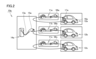
- FIG. 2 is a schematic diagram of a charging system including the conversion adapter shown in FIG.
- FIG. 3 is a schematic diagram showing a connection state of electrical power lines and the like during charging by the charging system.
- FIG. 4 is a schematic diagram illustrating the EMC filter according to the first embodiment.
- An electric vehicle is provided with an EMC filter that is connected to a charging station and suppresses common mode noise generated when charging.
- a conversion adapter is used to convert the interface.
- an EMC filter is designed for an electric vehicle assuming that the vehicle will be connected to a charging station of the same charging method.
- the impedance component seen from the charging inlet of the electric vehicle toward the charging station changes compared to when the conversion adapter is not used, which causes a problem that the common mode noise may not be sufficiently suppressed.
- one of the objectives is to provide a conversion adapter that can better suppress common mode noise when used.
- a conversion adapter is coupled between a charging inlet of a vehicle compatible with a first charging method and a charging connector of a charging cable connected to a charging station compatible with a second charging method, and connects a power line of the charging inlet and a power line of the charging cable.
- the conversion adapter includes a housing, a first charging connector compatible with the first charging method, a second charging connector compatible with the second charging method, power lines connected to the first charging connector and the second charging connector and disposed within the housing, and a first EMC filter that suppresses common mode noise generated in the power lines.
- the first EMC (Electromagnetic Compatibility) filter provided in the conversion adapter can suppress common mode noise generated in the power line.
- the first EMC filter may be attached to the housing in a replaceable manner. In this way, the first EMC filter can be replaced according to the standard of the charging cable of the charging station and the standard of the vehicle. This allows for more reliable charging.
- the first EMC filter may be disposed within the housing. In this way, since the first EMC filter is disposed within the housing, the first EMC filter can be protected by the housing. Therefore, it is possible to ensure stable use over a longer period of time.
- the first EMC filter may suppress common mode noise in conjunction with a second EMC filter provided in the vehicle that corresponds to the charging method of the vehicle. In this way, common mode noise can be suppressed more reliably.
- Fig. 1 is a schematic perspective view showing an external appearance of the conversion adaptor in the first embodiment of the present disclosure.
- Fig. 2 is a schematic diagram of a charging system including the conversion adaptor shown in Fig. 1.
- Fig. 3 is a schematic diagram showing a connection state of electrical power lines and the like during charging in the charging system.
- Fig. 4 is a schematic diagram showing an EMC filter in the first embodiment.
- the charging system 10a including the conversion adapter 11a in the first embodiment is a charging system that charges an electric vehicle, in this embodiment, an electric vehicle 12a.
- the charging in this disclosure is DC (direct current) charging.
- the charging system 10a includes the conversion adapter 11a and a charging stand 14a to which a charging cable 13a is connected.
- a charging connector 15a for the charging cable with a handle is provided at the end of the charging cable 13a connected to the charging stand 14a corresponding to a second charging method different from the first charging method described later.
- the conversion adapter 11a converts the charging method so that one of the charging methods matches the other charging method.
- the electric vehicle 12a side is equipped with a unit that takes measures against common mode noise, and the noise filter mounted on the conversion adapter 11a and the noise filter on the electric vehicle 12a side are combined to suppress common mode noise.
- the charging cable 13a includes multiple electric lines. Specifically, the charging cable 13a includes electric lines such as a positive power line 21a, a negative power line 22a, a ground line 23a for earthing, a first communication line 24a, a second communication line 25a, a first signal line 26a, a second signal line 27a, a third signal line 28a, and a fourth signal line 29a.
- electric lines such as a positive power line 21a, a negative power line 22a, a ground line 23a for earthing, a first communication line 24a, a second communication line 25a, a first signal line 26a, a second signal line 27a, a third signal line 28a, and a fourth signal line 29a.
- the electric vehicle 12a includes a vehicle charging inlet 16a that is compatible with the first charging method and serves as an interface for charging.
- the charging system 10a includes the charging inlet 16a of the electric vehicle 12a.
- the charging inlet 16a is provided with a charging socket 17a for vehicle charging, which is an insertion port for the charging connector 15a.
- the charging connector 15a is connected to this charging socket 17a to charge the electric vehicle 12a.
- the charging inlet 16a is provided with multiple electric lines corresponding to the charging cable 13a.
- the charging inlet 16a includes electric lines such as a positive power line 31a, a negative power line 32a, a ground line 33a for earthing, a first communication line 34a, a second communication line 35a, a first signal line 36a, and a second signal line 37a.
- the charging inlet 16a also includes a voltmeter 38a and a switch 39a provided on the second signal line 37a.
- the charging inlet 16a on the electric vehicle 12a side is equipped with thermistors 18a and 18b that detect the temperature during charging, and an EMC filter 19a (second EMC filter) that suppresses common mode noise generated in the power line when the charging socket 17a and charging connector 15a are connected during charging. If the temperature detected by thermistors 18a and 18b is higher than a predetermined temperature, it is determined that the charging state is abnormal and charging is stopped.
- the element values of the EMC filter 19a are designed so that it can sufficiently suppress common mode noise when it is connected to a charging stand that uses the same charging method as the charging method on the electric vehicle 12a side.
- the charging cable 13a and charging inlet 16a comply with the same standard, charging is possible by simply connecting the charging connector 15a directly to the charging socket 17a.
- the charging stand 14a, charging cable 13a, charging connector 15a, and charging socket 17a comply with different standards, charging cannot be achieved by simply connecting the charging connector 15a to the charging socket 17a.
- the conversion adapter 11a is used.
- the conversion adapter 11a includes a housing 20a, specifically, a first charging connector 51a corresponding to the first charging method, a second charging connector 52a corresponding to the second charging method, and a conversion cable 53a. That is, in this embodiment, the housing 20a included in the conversion adapter 11a includes the first charging connector 51a, the second charging connector 52a, and the conversion cable 53a. The first charging connector 51a and the second charging connector 52a are connected by the conversion cable 53a.
- the conversion cable 53a includes multiple electric lines, such as a positive power line.
- the first charging connector 51a can be connected to the charging connector 15a.
- the opening 54a and the arrangement of the power lines exposed in the opening 54a comply with the same standards as the charging stand 14a, the charging cable 13a, and the charging connector 15a.
- the second charging connector 52a can be connected to the charging socket 17a.
- the shape and arrangement of the protrusions 55a that are inserted into the charging socket 17a conform to the same standards as the charging socket 17a.
- the conversion cable 53a is provided with a plurality of electric lines corresponding to the charging cable 13a.
- the conversion cable 53a includes electric lines such as a positive power line 41a, a negative power line 42a, a ground line 43a for earthing, a first communication line 44a, a second communication line 45a, a first signal line 46a, a second signal line 47a, a third signal line 48a, and a fourth signal line 49a.
- the conversion cable 53a also includes a resistor 56a arranged between the ground line 43a and the first signal line 46a, a resistor 57a arranged in the second signal line 47a, and a resistor 58a arranged between the second signal line 47a and the fourth signal line 49a.
- the conversion adapter 11a includes an EMC filter 59a (first EMC filter) that suppresses common mode noise generated in the power lines, specifically, the positive power line 41a and the negative power line 42a.
- the EMC filter 59a is replaceably attached to the housing 20a.
- the EMC filter 59a is provided in the second charging connector 52a.
- the EMC filter 59a is composed of, for example, a magnetic core arranged on the outer periphery of two power lines, specifically, the positive power line 41a and the negative power line 42a, and an insulating holding part that holds the magnetic core.
- the conversion adapter 11b and the conversion adapter 11c are also provided with the EMC filter 59b (first EMC filter) and the EMC filter 59c (first EMC filter).
- the EMC filter 59a includes a first connector 61a, a second connector 62a, a common choke coil 63a, a first capacitor 64a, a second capacitor 65a, a first power line 71a, a second power line 72a, and a third power line 73a.
- the first power line 71a is connected to the first connector 61a and the second connector 62a.
- the second power line 72a is connected to the first connector 61a and the second connector 62a.
- the third power line 73a is connected to the first connector 61a and the second connector 62a.
- the first power line 71a, the second power line 72a, and the third power line 73a are each disposed between the first connector 61a and the second connector 62a.
- first connector 61a and the second connector 62a are provided at both ends of the first power line 71a, the second power line 72a, and the third power line 73a, respectively.
- the first connector 61a and the second connector 62a are connection terminals of the EMC filter 59a, and are attached to the second charging connector 52a using the first connector 61a and the second connector 62a.
- the common choke coil 63a is disposed so as to surround a portion of the first power line 71a and the second power line 72a.
- the first capacitor 64a is connected to the first power line 71a and the third power line 73a.
- the second capacitor 65a is connected to the second power line 72a and the third power line 73a.
- the conversion adapter 11a described above can suppress common mode noise generated in the power line by the EMC filter 59a provided in the conversion adapter 11a, even when it is connected between the charging inlet 16a of the electric vehicle 12a and the charging connector 15a of the charging cable 13a connected to the charging stand 14a.
- the EMC filter 59a is replaceably attached to the housing 20a. Therefore, the EMC filter 59a can be replaced according to the specifications of the charging cable 13a of the charging station 14a and the specifications of the electric vehicle 12a, which is the vehicle. This allows for even more reliable charging.
- the EMC filter 59a is disposed within the housing 20a. Therefore, since the EMC filter 59a is disposed within the housing 20a, the EMC filter 59a can be protected by the housing 20a. This ensures stable use over a longer period of time.
- the EMC filter 59a includes a first connector 61a and a second connector 62a that are connected to the power lines of the conversion adapter 11a, a first power line 71a that is connected to the first connector 61a and the second connector 62a, a second power line 72a that is connected to the first connector 61a and the second connector 62a, and a third power line 73a that is connected to the first connector 61a and the second connector 62a.
- the third power line 73a is connected to the ground line.
- earthing can be achieved by the third power line 73a that is connected to the ground line, allowing for safer charging.
- the EMC filter 59a suppresses common mode noise together with the EMC filter 19a that the vehicle has and that corresponds to the charging method of the vehicle. Therefore, common mode noise can be suppressed more reliably.
- the first power line 71a is connected to the positive power line 41a.
- the second power line 72a is connected to the negative power line 42a. This reliably suppresses common mode noise that occurs in the positive power line 41a and the negative power line 42a, and prevents erroneous detection of thermistors 18a and 18b. This allows for more reliable charging.
- the EMC filter is replaceably attached to the housing, but the present invention is not limited to this, and the housing and the EMC filter may be integrated together.
- the EMC filter is arranged inside the housing, but this is not limiting, and the EMC filter may be arranged outside the housing.
Landscapes
- Engineering & Computer Science (AREA)
- Power Engineering (AREA)
- Transportation (AREA)
- Mechanical Engineering (AREA)
- Charge And Discharge Circuits For Batteries Or The Like (AREA)
- Electric Propulsion And Braking For Vehicles (AREA)
Abstract
Cet adaptateur de conversion est connecté entre une entrée de charge d'un véhicule prenant en charge un premier procédé de charge et un connecteur de charge d'un câble de charge connecté à une station de charge prenant en charge un second procédé de charge, et est utilisé pour connecter une ligne électrique de l'entrée de charge et une ligne électrique du câble de charge. L'adaptateur de conversion comprend : un boîtier ; un premier connecteur de charge prenant en charge le premier procédé de charge ; un second connecteur de charge prenant en charge le second procédé de charge ; une ligne d'alimentation connectée au premier connecteur de charge et au second connecteur de charge, et placée dans le boîtier ; et un premier filtre CEM pour supprimer le bruit de mode commun généré dans la ligne d'alimentation.
Priority Applications (3)
| Application Number | Priority Date | Filing Date | Title |
|---|---|---|---|
| CN202380101166.XA CN121666328A (zh) | 2023-08-22 | 2023-08-22 | 转换适配器 |
| JP2025541213A JPWO2025041261A1 (fr) | 2023-08-22 | 2023-08-22 | |
| PCT/JP2023/030147 WO2025041261A1 (fr) | 2023-08-22 | 2023-08-22 | Adaptateur de conversion |
Applications Claiming Priority (1)
| Application Number | Priority Date | Filing Date | Title |
|---|---|---|---|
| PCT/JP2023/030147 WO2025041261A1 (fr) | 2023-08-22 | 2023-08-22 | Adaptateur de conversion |
Publications (1)
| Publication Number | Publication Date |
|---|---|
| WO2025041261A1 true WO2025041261A1 (fr) | 2025-02-27 |
Family
ID=94731522
Family Applications (1)
| Application Number | Title | Priority Date | Filing Date |
|---|---|---|---|
| PCT/JP2023/030147 Pending WO2025041261A1 (fr) | 2023-08-22 | 2023-08-22 | Adaptateur de conversion |
Country Status (3)
| Country | Link |
|---|---|
| JP (1) | JPWO2025041261A1 (fr) |
| CN (1) | CN121666328A (fr) |
| WO (1) | WO2025041261A1 (fr) |
Citations (4)
| Publication number | Priority date | Publication date | Assignee | Title |
|---|---|---|---|---|
| JP2013062978A (ja) * | 2011-09-14 | 2013-04-04 | Jfe Engineering Corp | 超急速充電対応電気自動車、及び、そのための超急速充電用ケーブルの支持構造 |
| JP2014183723A (ja) * | 2013-03-21 | 2014-09-29 | Denso Corp | 充電用接続装置 |
| JP2015207817A (ja) * | 2014-04-17 | 2015-11-19 | 株式会社オートネットワーク技術研究所 | 通信装置 |
| JP2016195540A (ja) * | 2008-11-18 | 2016-11-17 | ヴァレオ システム ドゥ コントロール モトゥール | 給電および充電に共用される電気装置 |
-
2023
- 2023-08-22 CN CN202380101166.XA patent/CN121666328A/zh active Pending
- 2023-08-22 WO PCT/JP2023/030147 patent/WO2025041261A1/fr active Pending
- 2023-08-22 JP JP2025541213A patent/JPWO2025041261A1/ja active Pending
Patent Citations (4)
| Publication number | Priority date | Publication date | Assignee | Title |
|---|---|---|---|---|
| JP2016195540A (ja) * | 2008-11-18 | 2016-11-17 | ヴァレオ システム ドゥ コントロール モトゥール | 給電および充電に共用される電気装置 |
| JP2013062978A (ja) * | 2011-09-14 | 2013-04-04 | Jfe Engineering Corp | 超急速充電対応電気自動車、及び、そのための超急速充電用ケーブルの支持構造 |
| JP2014183723A (ja) * | 2013-03-21 | 2014-09-29 | Denso Corp | 充電用接続装置 |
| JP2015207817A (ja) * | 2014-04-17 | 2015-11-19 | 株式会社オートネットワーク技術研究所 | 通信装置 |
Also Published As
| Publication number | Publication date |
|---|---|
| JPWO2025041261A1 (fr) | 2025-02-27 |
| CN121666328A (zh) | 2026-03-13 |
Similar Documents
| Publication | Publication Date | Title |
|---|---|---|
| US10576832B2 (en) | Electrical connecting device and charging cable for an electric vehicle | |
| JP5835152B2 (ja) | 車両用充電装置 | |
| CN109562700B (zh) | 包括机动车和连接机构的布置结构,机动车和连接机构 | |
| CN106715186B (zh) | 电气线缆和用于这种线缆的绕线设备 | |
| US20180208067A1 (en) | Charging device, charging system and charging method for electric vehicle | |
| JP2012151824A (ja) | 電力線通信システム、電力線通信装置及びコネクタ装置 | |
| JP3217205U (ja) | 電動車両を充電するための充電システム用のアダプタプラグ | |
| CN103579789A (zh) | 用于将线束连接至磁铁线的适配器 | |
| WO2012120945A1 (fr) | Système de communication par ligne électrique, dispositif connecteur et dispositif de communication par ligne électrique | |
| US12562560B2 (en) | Vehicle charging system for an electric vehicle having arc detection | |
| KR20110053047A (ko) | 전기차용 충전 플러그의 록킹장치 | |
| CN107005499B (zh) | 通信系统 | |
| JP2012100253A (ja) | コネクタ装置、電力線通信装置及び電力線通信システム | |
| US9216653B2 (en) | Method for charging an electric vehicle by supplying DC over a cable configured for AC charging | |
| JPH04115480A (ja) | 相対的に回転可能な2個の部品を電気的に接続する接続要素 | |
| JP2012135104A (ja) | 充電接続装置 | |
| WO2025041261A1 (fr) | Adaptateur de conversion | |
| JP2012169143A (ja) | コネクタ装置及び充電装置 | |
| EP3836339B1 (fr) | Dispositif de charge | |
| WO2025041262A1 (fr) | Filtre cem et système de charge | |
| JP6169385B2 (ja) | 充電コネクタ | |
| JP6933396B2 (ja) | コネクタ | |
| JP7330622B2 (ja) | 断線判定手段 | |
| KR20230088259A (ko) | 전기적 연결을 검출하기 위한 장치 | |
| CN108674203B (zh) | 充电电池用充放电插座、插头及包括其的电池箱 |
Legal Events
| Date | Code | Title | Description |
|---|---|---|---|
| 121 | Ep: the epo has been informed by wipo that ep was designated in this application |
Ref document number: 23949722 Country of ref document: EP Kind code of ref document: A1 |
|
| ENP | Entry into the national phase |
Ref document number: 2025541213 Country of ref document: JP Kind code of ref document: A |
|
| WWE | Wipo information: entry into national phase |
Ref document number: 2025541213 Country of ref document: JP |
|
| NENP | Non-entry into the national phase |
Ref country code: DE |