WO2025041252A1 - 真空バルブ及び真空バルブの製造方法 - Google Patents
真空バルブ及び真空バルブの製造方法 Download PDFInfo
- Publication number
- WO2025041252A1 WO2025041252A1 PCT/JP2023/030107 JP2023030107W WO2025041252A1 WO 2025041252 A1 WO2025041252 A1 WO 2025041252A1 JP 2023030107 W JP2023030107 W JP 2023030107W WO 2025041252 A1 WO2025041252 A1 WO 2025041252A1
- Authority
- WO
- WIPO (PCT)
- Prior art keywords
- bellows
- movable
- guide
- electrode bar
- vacuum valve
- Prior art date
- Legal status (The legal status is an assumption and is not a legal conclusion. Google has not performed a legal analysis and makes no representation as to the accuracy of the status listed.)
- Pending
Links
Images


Classifications
-
- H—ELECTRICITY
- H01—ELECTRIC ELEMENTS
- H01H—ELECTRIC SWITCHES; RELAYS; SELECTORS; EMERGENCY PROTECTIVE DEVICES
- H01H33/00—High-tension or heavy-current switches with arc-extinguishing or arc-preventing means
- H01H33/60—Switches wherein the means for extinguishing or preventing the arc do not include separate means for obtaining or increasing flow of arc-extinguishing fluid
- H01H33/66—Vacuum switches
- H01H33/662—Housings or protective screens
-
- H—ELECTRICITY
- H02—GENERATION; CONVERSION OR DISTRIBUTION OF ELECTRIC POWER
- H02B—BOARDS, SUBSTATIONS OR SWITCHING ARRANGEMENTS FOR THE SUPPLY OR DISTRIBUTION OF ELECTRIC POWER
- H02B13/00—Arrangement of switchgear in which switches are enclosed in, or structurally associated with, a casing, e.g. cubicle
- H02B13/02—Arrangement of switchgear in which switches are enclosed in, or structurally associated with, a casing, e.g. cubicle with metal casing
- H02B13/035—Gas-insulated switchgear
- H02B13/045—Details of casing, e.g. gas tightness
Definitions
- This disclosure relates to a vacuum valve and a method for manufacturing the vacuum valve.
- a vacuum valve installed as an arc extinguishing chamber in a vacuum circuit breaker and vacuum switchgear comprises an insulating container that maintains a vacuum state, a fixed electrode, a movable electrode, and a bellows.
- the insulating container has a fixed end plate and a movable end plate at each end.
- the fixed electrode is fixed to the insulating container via the fixed end plate.
- the movable electrode is joined to the movable end plate via the bellows.
- One end of the bellows is joined to the movable end plate, and the other end is joined to the movable electrode.
- the movable electrode is joined to an operating mechanism outside the insulating container. This makes it possible to open and close the vacuum valve while maintaining the degree of vacuum inside the insulating container.
- Vacuum valves are placed inside tanks and may be used in an atmosphere of pressurized dry air or insulating gas such as sulfur hexafluoride gas. Because there is a vacuum inside the insulating container, the bellows is subjected to the differential pressure between the vacuum and the insulating gas from outside the insulating container. If this differential pressure is large, the bellows will buckle. Then, the opening and closing action of the vacuum valve will cause the bellows to break early, resulting in a vacuum leak. For this reason, the bellows must be used in a low-pressure gas atmosphere. However, low-pressure insulating gas has poorer insulating performance than high-pressure insulating gas. This has meant that it has been necessary to increase the size of the products, for example by lengthening the insulation distance of each component of the vacuum circuit breaker and vacuum switchgear.
- the vacuum valve in Patent Document 1 has another bellows on the back surface of the movable end plate.
- this configuration it is possible to create three gas compartments: inside the vacuum valve, inside the bellows, and outside the vacuum valve. This distributes the pressure load and prevents the bellows from buckling and displacing, making it possible to use the bellows even in a high-pressure insulating gas atmosphere.
- the back surface of the movable end plate is also equipped with bellows, which increases the overall length of the vacuum valve.
- the overall length of the vacuum valve increases, the overall size of the vacuum circuit breaker and vacuum switchgear also increases.
- the mass increases, which increases the inertial force generated when the vacuum valve starts or ends its opening and closing operation. This makes it necessary to increase the mechanical strength of the operating mechanism, etc.
- the present disclosure has been made to solve the above-mentioned problems, and aims to provide a vacuum valve and a method for manufacturing the vacuum valve that can prevent buckling displacement of the bellows without extending the entire length of the vacuum valve or the movable electrode.
- the vacuum valve according to the present disclosure is characterized by comprising an insulating container that maintains a vacuum inside and has a fixed end plate and a movable end plate at each end, a fixed electrode bar fixed to the fixed end plate and having a fixed contact joined to its end, a movable electrode bar arranged on the movable end plate and having a movable contact joined to its end so that it can be moved toward and away from the fixed contact, and a bellows with one end joined to the movable end plate and the other end joined to the movable electrode bar, having a bellows structure that can expand and contract in the driving direction of the movable electrode bar, and the valley of the bellows structure coming into contact with the movable electrode bar.
- the vacuum valve according to the present disclosure is characterized by comprising: an insulating container that maintains a vacuum inside and has a fixed end plate and a movable end plate at each end; a fixed electrode bar fixed to the fixed end plate and having a fixed contact joined to its end; a movable electrode bar arranged on the movable end plate and having a movable contact joined to its end, arranged so as to be movable and detachable from the fixed contact; a bellows having one end joined to the movable end plate and the other end joined to the movable electrode bar, and having a bellows structure that can expand and contract in the driving direction of the movable electrode bar; a first guide joined to the other end of the bellows, with an outer periphery in contact with the valley portion of the bellows structure and an inner periphery in contact with the movable electrode bar, and having a protrusion; and a second guide joined to the movable end plate, with an outer periphery in contact with the
- the vacuum valve according to the present disclosure is characterized by comprising an insulating container that maintains a vacuum inside and has a fixed end plate and a movable end plate at each end, a fixed electrode bar fixed to the fixed end plate and having a fixed contact joined to its end, a movable electrode bar arranged on the movable end plate and having a movable contact joined to its end, arranged so that it can be moved toward and away from the fixed contact, a bellows with one end joined to the movable end plate and the other end joined to the movable electrode bar, having a bellows structure that can expand and contract in the driving direction of the movable electrode bar, and a thin ring or ring segment with a U-shaped cross section inserted into the valley of the bellows structure.
- the manufacturing method of the vacuum valve according to the present disclosure is characterized by comprising the steps of fitting together a number of cylindrical bodies of different diameters to produce a multi-layered cylindrical body, forming the side walls of the multi-layered cylindrical body into a bellows shape to produce a multi-layered bellows having a bellows structure, sealing the spaces between the layers at both ends of the multi-layered bellows, and positioning the multi-layered bellows so that the valleys of the bellows structure of the multi-layered bellows come into contact with the movable electrode bar.
- the valley portion of the bellows' bellows structure comes into contact with the movable electrode rod or guide.
- a thin plate ring or a divided ring body with a U-shaped cross section is joined to the valley portion of the bellows' bellows structure.
- FIG. 1 is a schematic cross-sectional view of a vacuum interrupter according to a first embodiment.
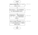
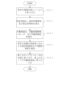
- 4 is a flowchart showing a manufacturing process of the bellows according to the first embodiment.
- 5A to 5C are schematic diagrams illustrating a process for producing a multilayer cylindrical body according to the first embodiment.
- 5A to 5C are schematic cross-sectional views illustrating a process for producing a bellows shape of the bellows according to the first embodiment.
- 4 is a schematic cross-sectional view illustrating a process of sealing between layers at both ends of the multi-layer bellows of embodiment 1.
- FIG. 4 is a flowchart showing an assembly process of the vacuum interrupter of the first embodiment.
- 11 is a schematic cross-sectional view of a vacuum interrupter according to a second embodiment.
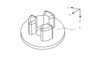
- FIG. 11 is a perspective view of a first guide according to a second embodiment.
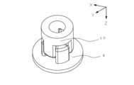
- FIG. 11 is a perspective view of a second guide according to the second embodiment.
- FIG. 11 is a perspective view of a first guide and a second guide according to a second embodiment.
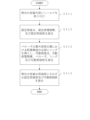
- 10 is a flowchart showing an assembly process of the vacuum interrupter of the second embodiment.
- 11 is a schematic cross-sectional view of a vacuum interrupter according to a third embodiment.
- FIG. FIG. 11 is a schematic cross-sectional view of a bellows according to a third embodiment.
- FIG. 11 is a perspective view of a divided body of a ring according to a third embodiment.
- 11 is a flowchart showing an assembly process of the vacuum interrupter of the third embodiment.
- the coordinate axes of the XYZ Cartesian coordinate system are shown in the diagram.
- the direction in which the movable electrode 3 is driven is the Z-axis direction
- the direction in which the movable electrode 3 approaches the fixed electrode 2 is the +Z-axis direction
- the direction in which it moves away is the -Z-axis direction.
- the direction from the fixed electrode 2 toward the shield 4 is the Y-axis direction
- the direction from the fixed electrode 2 toward the shield 4a is the +Y-axis direction
- the direction from the fixed electrode 2 toward the shield 4b is the -Y-axis direction.
- the direction from the back to the front is the +X-axis direction
- the direction from the front to the back is the -X-axis direction.
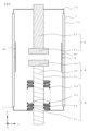
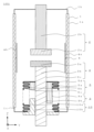
- FIG. 1 is a schematic cross-sectional view of the vacuum valve 100 in accordance with the first embodiment.
- the vacuum valve 100 includes an insulating container 1, a fixed electrode 2, a movable electrode 3, a bellows 5, and a shield 4.
- the insulating container 1 has a cylindrical container 1a made of ceramics or the like, and a fixed end plate 1b and a movable end plate 1c provided at both ends of the cylindrical container 1a.
- the fixed end plate 1b and the movable end plate 1c are brazed to the cylindrical container 1a, and the inside of the insulating container 1 is maintained in a vacuum.
- the insulating container 1 has a fixed electrode 2 and a movable electrode 3 at both ends, and has a shield 4 and a bellows 5 inside.
- the shield 4 is arranged to surround the fixed electrode 2 and the movable electrode 3, and protects the inner surface of the insulating container 1.
- the fixed electrode 2 has a fixed contact 2a and a fixed electrode rod 2b.
- the fixed contact 2a is joined to the end of the fixed electrode rod 2b.
- the fixed electrode rod 2b is fixed to the insulating container 1 via the fixed end plate 1b.
- the movable electrode 3 has a movable contact 3a and a movable electrode rod 3b.
- the movable contact 3a is joined to the end of the movable electrode bar 3b and is arranged so that it can be brought into contact with and separated from the fixed contact 2a.
- One end of the bellows 5 is joined to the movable end plate 1c and the other end is joined to the movable electrode bar 3b.
- the movable electrode 3 is joined to an operating mechanism (not shown) outside the insulating container 1. This allows the vacuum valve 100 to be opened and closed while maintaining the degree of vacuum inside the insulating container 1.
- the bellows 5 has a bellows structure that can expand and contract in the Z-axis direction, which is the driving direction of the movable electrode bar 3b. It is preferable that the bellows 5 has a multi-layer structure. In this case, the layer 5a on the innermost diameter side of the bellows 5 is the layer closest to the movable electrode bar 3b in the multi-layer structure.
- the bellows 5 also has a valley portion 5b of the bellows structure and a abdomen portion 5c, which is the portion other than the valley portion of the bellows structure. The bellows 5 is arranged so that the valley portion 5b of the bellows structure in the innermost diameter side layer 5a contacts the movable electrode bar 3b.
- the valley portion 5b of the bellows structure it is not necessary for the entire circumference of the valley portion 5b of the bellows structure to contact the movable electrode bar 3b. In other words, it is sufficient for only a portion of the valley portion 5b of the bellows structure to contact the movable electrode bar 3b. This suppresses buckling displacement of the bellows 5 in the XY plane direction.
- the valley 5b of the bellows structure in the innermost layer 5a comes into contact with the movable electrode rod 3b, friction occurs between the valley 5b of the bellows structure and the movable electrode rod 3b when the vacuum valve 100 is opened or closed. This reduces the transient vibration of the bellows 5 and improves the fatigue strength of the bellows 5.
- the bellows 5 has a multi-layer structure.
- the multi-layer structure of the bellows 5 may be structured such that the layers are sealed at both ends, and the layers are not sealed except at both ends of the multi-layer structure.
- vacuum leakage can be prevented unless a crack occurs in any of the layers of the multi-layer structure. This can improve the opening and closing life of the vacuum valve 100.
- the multi-layer structure of the bellows 5 is not sealed except at both ends, it is structured such that slippage occurs between the layers. This can reduce transient vibrations of the bellows 5 and improve the fatigue strength of the bellows 5.
- At least one of the valley portion 5b of the bellows structure of the innermost layer 5a of the bellows 5 and the outer periphery 3c of the movable electrode rod 3b may be coated with an insulating material.
- a resin part or the like may be sandwiched between the movable end plate 1c and the current-carrying part. This makes it possible to prevent the interruption current from flowing through the bellows 5 when the vacuum valve 100 is opened to interrupt the current.
- the movable electrode bar 3b in FIG. 1 is a cylinder, it may be a rectangular column. Even in this case, the bellows 5 is positioned so that the valley portion 5b of the bellows structure in the innermost layer 5a is in contact with the movable electrode bar 3b.
- FIG. 2 is a flow chart showing the steps of producing the bellows of the first embodiment.
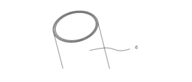
- Figure 3 is a schematic diagram showing the steps of producing the multilayered cylindrical body of the first embodiment.
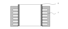
- Figure 4 is a schematic cross-sectional view showing the steps of producing the bellows shape of the bellows of the first embodiment.
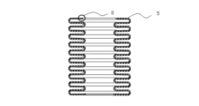
- Figure 5 is a schematic cross-sectional view showing the steps of sealing between the layers at both ends of the multilayered bellows of the first embodiment.
- step S101 a plurality of cylindrical bodies having different diameters are fitted together to produce a multi-layered cylindrical body 6.
- Fig. 3 shows the steps of producing a two-layered cylindrical body, a three-layered or more cylindrical body may be produced.
- step S102 the multi-layered cylindrical body 6 is inserted into a cavity of a die 7, and the side wall of the multi-layered cylindrical body 6 is hydraulically formed into a bellows shape.
- the die 7 has a cavity capable of housing the cylindrical body therein.
- the cavity also has an inner wall carved into a wave shape. This makes it possible to manufacture a multi-layered bellows 5 having a bellows structure.
- step S103 the spaces between the layers of the multi-layered bellows 5 are not sealed apart from the two end portions 8, but are sealed between the layers at the two end portions 8 by brazing. This completes the process for producing the bellows 5 in the first embodiment.
- Fig. 6 is a flow chart showing the assembly process of the vacuum interrupter of the first embodiment.
- the shield 4 is attached to the inside of a cylindrical container 1a made of ceramics or the like.
- the fixed contact 2a, the fixed electrode bar 2b, and the fixed end plate 1b are brazed together.
- the movable contact 3a, the movable electrode bar 3b, the bellows 5, and the movable end plate 1c are brazed together.
- the bellows 5 is arranged so that the valley portion 5b of the bellows structure in the innermost layer 5a contacts the movable electrode bar 3b.
- step S114 the fixed end plate 1b and the movable end plate 1c are brazed to both ends of the cylindrical container 1a, respectively.
- the movable contact 3a is disposed so as to be movable toward and away from the fixed contact 2a. This completes the assembly process of the vacuum interrupter 100 in the first embodiment.
- the valley portion 5b of the bellows structure in the innermost layer 5a of the bellows 5 is arranged so as to contact the movable electrode bar 3b.
- the multi-layer structure of the bellows 5 may be such that the layers are sealed at both ends, and the layers are not sealed except at both ends. With the above configuration, vacuum leakage can be prevented unless a tear occurs in all layers of the multi-layer structure. For example, even if the valley portion 5b of the bellows structure in the innermost layer 5a is worn away by friction with the movable electrode rod 3b and a tear occurs in the valley portion 5b of the bellows structure in the innermost layer 5a, the layers are sealed at both ends of the bellows 5, so that vacuum leakage from the gaps between the layers can be prevented. This can improve the opening and closing life of the vacuum valve 100. Furthermore, the multi-layer structure of the bellows 5 is such that the layers are not sealed except at both ends, so that slippage occurs between the layers. This can reduce transient vibration of the bellows 5 and improve the fatigue strength of the bellows 5.
- At least one of the valley portion 5b of the bellows structure of the innermost layer 5a and the outer periphery 3c of the movable electrode rod 3b may be coated with an insulating material.
- the movable electrode bar 3b in FIG. 1 may be a rectangular column. Even in this case, the bellows 5 is arranged so that the valley portion 5b of the bellows structure in the innermost layer 5a is in contact with the movable electrode bar 3b. This provides the same effect of suppressing buckling displacement of the bellows 5 in the XY plane direction.
- the manufacturing method of the vacuum valve 100 in the first embodiment includes the steps of fitting together a plurality of cylindrical bodies with different diameters to manufacture a multi-layered cylindrical body 6, forming the side walls of the multi-layered cylindrical body into a bellows shape to manufacture a multi-layered bellows 5 having a bellows structure, sealing the spaces between the layers at both ends 8 of the multi-layered bellows 5, and arranging the bellows 5 so that the valleys 5b of the bellows structure of the multi-layered bellows 5 come into contact with the movable electrode bar 3b.
- the above manufacturing method also allows the manufacture of a bellows 5 that has a multi-layered structure and in which the spaces between the layers at both ends 8 are sealed. This prevents vacuum leakage unless a tear occurs in any of the layers of the multi-layered structure of the bellows 5.
- the bellows 5 is described as having a multi-layer structure, but it may have a single-layer structure. Even in this case, the bellows 5 is arranged so that the valley portion 5b of the bellows structure is in contact with the movable electrode bar 3b. This provides the same effect of preventing the bellows 5 from buckling and displacing in the XY plane.
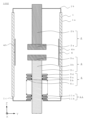
- FIG. 7 is a schematic cross-sectional view of the vacuum valve 101 in the second embodiment.
- the vacuum valve 100 in the first embodiment is characterized in that the valley portion 5b of the bellows structure in the innermost layer 5a of the bellows 5 is arranged so as to contact the movable electrode bar 3b.
- the vacuum valve 101 in the second embodiment is different from the vacuum valve 100 in the first embodiment in that it includes a first guide 9 and a second guide 10, and that the valley portion 5b of the bellows structure in the innermost layer 5a of the bellows 5 is arranged so as to contact at least one of the outer periphery 9a of the first guide 9 and the outer periphery 10a of the second guide 10.
- the same reference numerals are used for the same configurations as in the first embodiment.
- the first guide 9 is joined to the other end of the bellows 5.
- the outer periphery 9a of the first guide 9 is positioned so as to contact the valley portion 5b of the bellows structure in the innermost layer 5a of the bellows 5.
- the inner periphery 9b of the first guide 9 is positioned so as to contact the movable electrode bar 3b.
- the second guide 10 is joined to the movable end plate 1c.
- the outer periphery 10a of the second guide 10 is positioned so as to contact the valley portion 5b of the bellows structure in the innermost layer 5a of the bellows 5.
- the inner periphery 10b of the second guide 10 is positioned so as to contact the movable electrode bar 3b.
- FIG. 8 is a perspective view of the first guide 9 of embodiment 2
- FIG. 9 is a perspective view of the second guide 10 of embodiment 2
- FIG. 10 is a perspective view of the first guide 9 and the second guide 10 of embodiment 2.
- the first guide 9 and the second guide 10 have protrusions that can be fitted into each other.
- the first guide 9 and the second guide 10 are arranged so that the protrusions can be fitted into each other.
- first guide 9 and the second guide 10 are arranged so that at least one of the outer periphery 9a of the first guide 9 and the outer periphery 10a of the second guide 10 contacts the valley portion 5b of the bellows structure in the innermost layer 5a of the bellows 5. This prevents the bellows 5 from buckling and displacing in the XY plane.
- the entire circumference of the valley portion 5b of the bellows structure does not have to be in contact with the first guide 9 and the second guide 10. In other words, it is sufficient that a portion of the valley portion 5b of the bellows structure is in contact with at least one of the first guide 9 and the second guide 10.
- the material of the first guide 9 and the second guide 10 be an insulating material such as a resin material, and that the bellows 5 is structured so that no current flows through it.
- the vacuum valve 101 has a structure in which a resin part or the like is sandwiched between the movable end plate 1c and the current-carrying part.
- the vacuum valve 101 has a structure in which the outer periphery 9a of the first guide 9, the outer periphery 10a of the second guide 10, and the movable end plate 1c, which come into contact with the bellows 5, are insulated from one another. This makes it possible to prevent the interruption current from flowing through the bellows 5 when the vacuum valve 101 is opened to interrupt the current.
- the manufacturing process for the bellows 5 is the same as the manufacturing process for the bellows 5 in the first embodiment.
- Fig. 11 is a flow chart showing the assembly process of the vacuum interrupter according to the second embodiment.
- the shield 4 is attached to the inside of a cylindrical container 1a made of ceramics or the like.
- the fixed contact 2a, the fixed electrode bar 2b, and the fixed end plate 1b are brazed together.
- the movable contact 3a, the movable electrode bar 3b, the bellows 5, and the movable end plate 1c are brazed together.
- the bellows 5 is arranged so that the valley portion 5b of the bellows structure in the innermost layer 5a contacts the movable electrode bar 3b.
- steps S211 to S213 is not limited to the above, and may be changed or may be performed simultaneously.
- step S214 the fixed end plate 1b and the movable end plate 1c are brazed to both ends of the cylindrical container 1a.
- the movable contact 3a is arranged so as to be movable toward and away from the fixed contact 2a.
- step S215 the first guide 9 is attached to the other end of the bellows 5, and the second guide 10 is attached to the movable end plate 1c.
- step S215 the first guide 9 and the second guide 10 are positioned so that at least one of the outer periphery 9a of the first guide 9 and the outer periphery 10a of the guide 10 contacts the valley portion 5b of the bellows structure in the innermost layer 5a of the bellows 5. This completes the assembly process of the vacuum interrupter 101 in the second embodiment.
- the vacuum valve 101 in embodiment 2 has a first guide 9 and a second guide 10.
- the first guide 9 is joined to the other end of the bellows 5, and the outer periphery 9a of the first guide 9 contacts the valley portion 5b of the bellows structure of the bellows 5, the inner periphery 9b contacts the movable electrode bar 3b, and has a protrusion.
- the second guide 10 is joined to the movable end plate 1c, and the outer periphery 10a of the second guide 10 contacts the valley portion 5b of the bellows structure of the bellows 5, the inner periphery 10b of the second guide 10 contacts the movable electrode bar 3b, and has a protrusion that can be fitted into the first guide 9. This prevents the bellows 5 from buckling and displacing in the XY plane.
- the first guide 9 or the second guide 10 comes into contact with the valley portion 5b of the bellows structure when the vacuum valve 101 is opened or closed, thereby reducing transient vibration of the bellows 5.
- This improves the opening and closing life of the vacuum valve 101 compared to a configuration in which the vacuum valve 101 is configured with only either the first guide 9 or the second guide 10.
- the first guide 9 and the second guide 10 may also be made of an insulating material such as a resin material.
- first guide 9 and the second guide 10 may be made of a material that reduces wear when sliding against the bellows 5 compared to when the first guide 9 and the second guide 10 are made of metal.
- wear on the bellows 5 due to sliding friction is reduced, and the occurrence of cracks in the valleys 5b of the bellows structure is suppressed. This makes it easier to apply a single-layer bellows 5. This reduces the size of the bellows 5, and therefore the size of the vacuum valve 101 can be reduced.
- the manufacturing method of the vacuum valve 101 in the second embodiment includes the steps of fitting together a plurality of cylindrical bodies of different diameters to produce a multi-layered cylindrical body 6, forming the side walls of the multi-layered cylindrical body into a bellows shape to produce a multi-layered bellows 5 having a bellows structure, sealing the spaces between the layers at both ends 8 of the multi-layered bellows 5, and arranging the outer periphery 9a of the first guide 9 and the outer periphery 10a of the second guide 10 so that at least one of them contacts the valley 5b of the bellows structure in the innermost layer 5a of the bellows 5.
- the valley 5b of the bellows structure of the bellows 5 contacts at least one of the outer periphery 9a of the first guide 9 and the outer periphery 10a of the second guide 10, so that the vacuum valve 101 can be manufactured that can suppress buckling displacement of the bellows 5.
- the above manufacturing method also allows the manufacture of a bellows 5 that has a multi-layered structure and in which the spaces between the layers at both ends 8 are sealed. This makes it possible to prevent vacuum leakage unless a crack occurs in any of the layers of the multi-layer structure of the bellows 5.
- the bellows 5 in the second embodiment has been described as having a multi-layer structure, it may have a single-layer structure. Even in this case, the bellows 5 is arranged so that at least one of the outer periphery 9a of the first guide 9 and the outer periphery 10a of the second guide 10 contacts the valley portion 5b of the bellows structure of the bellows 5. This provides the same effect of suppressing buckling displacement of the bellows 5 in the XY plane direction.
- the movable electrode bar 3b in FIG. 7 is a cylinder, it may be a rectangular prism.
- the cross sections of the inner periphery 9b of the first guide 9 and the inner periphery 10b of the second guide 10 have the same polygonal shape as the cross section of the rectangular prism.
- the cross sections of the outer periphery 9a of the first guide 9 and the outer periphery 10a of the second guide 10 may be polygonal. Even in this case, the first guide 9 and the second guide 10 are arranged so that at least one of the outer periphery 9a of the first guide 9 and the outer periphery 10a of the second guide 10 contacts the valley portion 5b of the bellows structure in the innermost layer 5a of the bellows 5. This provides the same effect of suppressing buckling displacement of the bellows 5 in the XY plane direction.
- FIG. 12 is a schematic cross-sectional view of the vacuum valve 102 in the third embodiment.
- the vacuum valve 100 in the first embodiment is characterized in that the valley 5b of the bellows structure in the innermost layer 5a of the bellows 5 is arranged so as to contact the movable electrode bar 3b.
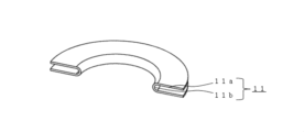
- the vacuum valve 102 in the third embodiment includes a thin ring 11 having a U-shaped cross section.
- the ring 11 is not limited to an annular shape, and may be a divided ring shape as shown in FIG. 14. In the following, the ring 11 is used as a general term for an annular ring and a divided body of an annular ring.
- the vacuum valve 102 in the third embodiment is different from the vacuum valve 100 in the first embodiment in that the ring 11 is inserted into the valley 5b of the bellows structure in the outermost layer 5d of the bellows 5.
- the same components as those in the first embodiment are designated by the same reference numerals.
- FIG. 13 is a schematic cross-sectional view of the bellows 5 of the third embodiment.
- FIG. 14 is a perspective view of a divided body of the ring 11 of the third embodiment. As shown in FIG. 14, the ring 11 is a thin plate and has a U-shaped cross section. The ring 11 is inserted into the valley portion 5b of the bellows structure in the layer 5d on the outermost diameter side of the bellows 5. This reinforces the bellows 5 with the ring 11, increasing the rigidity of the bellows 5 and suppressing buckling displacement of the bellows 5 in the XY plane.
- the ring 11 is joined to the outermost layer 5d at the abdomen 11a, which corresponds to the side of the U-shape of the ring 11, and is not joined to the outermost layer 5d at the R portion 11b, which corresponds to the valley of the U-shape of the ring 11.
- the manufacturing process for the bellows 5 is the same as the manufacturing process for the bellows 5 in the first embodiment.
- Fig. 15 is a flow chart showing the assembly process of the vacuum interrupter according to the third embodiment.
- the shield 4 is attached to the inside of a cylindrical container 1a made of ceramics or the like.
- the fixed contact 2a, the fixed electrode bar 2b, and the fixed end plate 1b are brazed together.
- the ring 11 is inserted into the valley portion 5b of the bellows structure in the outermost layer 5d of the bellows 5, and the movable contact 3a, the movable electrode rod 3b, the bellows 5, the ring 11 and the movable end plate 1c are brazed together.
- steps S311 to S313 is not limited to the above-mentioned order, and the order may be changed or steps may be performed simultaneously.
- step S314 the fixed end plate 1b and the movable end plate 1c are brazed to both ends of the cylindrical container 1a, respectively.
- the movable contact 3a is disposed so as to be movable toward and away from the fixed contact 2a. This completes the assembly process of the vacuum interrupter 102 in the third embodiment.
- the vacuum valve 102 in this embodiment has a ring 11 inserted into the valley portion 5b of the bellows structure in the layer 5d on the outermost diameter side of the bellows 5. This reinforces the bellows 5 with the ring 11, increasing the rigidity of the bellows 5 and suppressing buckling displacement of the bellows 5 in the XY plane direction. Furthermore, with the above configuration, it is possible to reduce transient vibrations of the bellows 5 and improve the fatigue strength of the bellows 5.
- the ring 11 has a structure in which the abdomen 11a of the ring 11 is joined to the outermost layer 5d, and the R portion 11b of the ring 11 is not joined to the outermost layer 5d.
- This makes it possible to suppress an increase in the thickness of the bellows 5 compared to when the ring 11 is joined to the outermost layer 5d at the R portion 11b of the ring 11.
- it is possible to suppress an increase in bending stress in the valley portion 5b of the bellows structure of the bellows 5 during the opening and closing operation of the vacuum valve 102. This makes it possible to improve the fatigue life of the bellows 5.
- the R portion 11b of the ring 11 and the layer 5d on the outermost diameter side may be structured so as not to come into contact with each other. Even in this case, the ring 11 reinforces the bellows 5, increasing the rigidity of the bellows 5, and thus provides the same effect of suppressing buckling displacement of the bellows 5 in the XY plane direction.
- the manufacturing method of the vacuum valve 102 in this embodiment includes the steps of fitting together a plurality of cylindrical bodies of different diameters to produce a multi-layered cylindrical body 6, forming the side walls of the multi-layered cylindrical body into a bellows shape to produce a multi-layered bellows 5 having a bellows structure, sealing the gaps between the layers at both ends 8 of the multi-layered bellows 5, and inserting the ring 11 or a divided body of the ring 11 into the valley 5b of the bellows structure in the outermost layer 5d of the bellows 5.
- the bellows 5 is reinforced by the ring 11, so that the vacuum valve 102 capable of suppressing buckling displacement of the bellows 5 can be manufactured.
- the above manufacturing method also makes it possible to manufacture a bellows 5 having a multi-layered structure and in which the gaps between the layers at both ends 8 are sealed. As a result, vacuum leakage can be prevented unless a tear occurs in all layers of the multi-layered structure of the bellows 5.
- the bellows 5 is described as having a multi-layer structure, but it may have a single-layer structure. Even in this case, the ring 11 is inserted into the valley portion 5b of the bellows structure. This provides the same effect of preventing the bellows 5 from buckling and displacing in the XY plane.
- the divided bodies of the ring 11 in FIG. 12 are described as ring 11 divided into two, the number of divisions is not limited to one. In other words, a divided body of the ring 11 divided two or more times may be inserted into the valley portion 5b of the bellows structure in the layer 5d on the outermost diameter side. Even in this case, the same effect of suppressing buckling displacement of the bellows 5 in the XY plane direction is achieved.
- the ring 11 does not have to be inserted into all of the valleys 5b of the bellows structure in the outermost layer 5d of the bellows 5.
- the ring 11 may be inserted into the valleys 5b of the bellows structure at both ends of the bellows 5 that have a large expansion and contraction range in the Z-axis direction, which is the driving direction of the movable electrode bar 3b, or in the center of the bellows 5 where buckling is likely to occur.
- rings 11 it is not necessary for all the rings 11 to have the same plate thickness.
- thicker rings 11 may be inserted in the valleys 5b of the bellows structure at both ends of the bellows 5 where the expansion and contraction width in the Z-axis direction, which is the driving direction of the movable electrode bar 3b, is large, or in the center of the bellows 5 where buckling is likely to occur.
- rings 11 that are thinner than the rings 11 inserted at both ends and the center of the bellows 5 may be inserted in places other than both ends and the center of the bellows 5.
Landscapes
- Engineering & Computer Science (AREA)
- Power Engineering (AREA)
- High-Tension Arc-Extinguishing Switches Without Spraying Means (AREA)
Abstract
真空バルブ(100、101)は、ベローズ(5)の蛇腹構造の谷部(5b)が可動側電極棒(3b)又はガイド(9、10)と接触する。又は、真空バルブ(102)は、薄板で断面がU字状のリング(11)又はリングの分割体(11)が、ベローズ(5)の蛇腹構造の谷部(5b)に挿入される。これにより、ベローズ(5)が座屈変位することを抑制可能な真空バルブ(100、101、102)及び真空バルブ(100、101、102)の製造方法を提供することができる。
Description
本開示は、真空バルブ及び真空バルブの製造方法に関する。
例えば真空遮断器及び真空開閉器に消弧室として搭載される真空バルブは、真空状態を保持する絶縁容器、固定側電極、可動側電極及びベローズを備える。絶縁容器は、両端部にそれぞれ固定側端板及び可動側端板を有する。固定側電極は、固定側端板を介して絶縁容器に固定されている。可動側電極は、ベローズを介して可動側端板に接合されている。また、ベローズは、一端が可動側端板に接合され、他端が可動側電極に接合されている。そして、可動側電極は、絶縁容器外で操作機構と接合される。これにより、絶縁容器内の真空度を保持しながら真空バルブの開閉動作が可能となる。
真空バルブは、タンク内などに配置され、乾燥空気又は六フッ化硫黄ガス等の絶縁ガスを加圧した雰囲気で使用される場合がある。絶縁容器内は真空であるため、ベロ-ズには、真空と絶縁ガスの差圧が絶縁容器外から負荷される。この差圧が大きいと、ベローズの座屈が発生する。そして、真空バルブの開閉動作によって、ベローズが早期に破断して真空漏れに至る。そのため、ベロ-ズは低圧ガス雰囲気中で使用する必要がある。しかし、低圧の絶縁ガスは、高圧の絶縁ガスに比べて絶縁性能が低下する。よって、真空遮断器及び真空開閉器の各部品の絶縁距離を長くするなど、製品を大型化する必要があった。
そこで、例えば特許文献1の真空バルブは、可動側端板の背面にもう一つベローズを備えている。この構成にすることで、真空バルブ内、ベロ-ズ内、真空バルブ外の三つのガス区分を設けることができる。これにより、圧力負荷が分散され、ベローズが座屈変位することが抑制されるので、高圧絶縁ガス雰囲気中でもベローズを使用可能となる。
しかしながら、特許文献1に記載の発明では、可動側端板の背面にもベローズを備えているため、真空バルブ全長が長くなる。真空バルブ全長が長くなると、真空遮断器及び真空開閉器全体のサイズが大きくなる。また、可動側電極のサイズが大きくなると、質量も大きくなるため、真空バルブの開閉動作開始時または終了時に発生する慣性力が増加する。これにより、操作機構などの機械強度を上げる必要がある。
本開示は、上述した課題を解決するためになされたものであり、真空バルブ全長及び可動側電極を伸長させずに、ベローズが座屈変位することを抑制可能な真空バルブ及び真空バルブの製造方法を提供することを目的とするものである。
本開示に係る真空バルブは、内部を真空に保持し、両端部にそれぞれ固定側端板及び可動側端板を有する絶縁容器と、固定側端板に固定され、端部に固定側接点が接合された固定側電極棒と、可動側端板に配置され、固定側接点に対して接離可能に配置された可動側接点が端部に接合された可動側電極棒と、一端が可動側端板に接合され、他端が可動側電極棒に接合され、可動側電極棒の駆動方向に伸縮自在な蛇腹構造を有し、蛇腹構造の谷部が可動側電極棒と接触するベローズと、を備えることを特徴とする。
また、本開示に係る真空バルブは、内部を真空に保持し、両端部にそれぞれ固定側端板及び可動側端板を有する絶縁容器と、固定側端板に固定され、端部に固定側接点が接合された固定側電極棒と、可動側端板に配置され、固定側接点に対して接離可能に配置された可動側接点が端部に接合された可動側電極棒と、一端が可動側端板に接合され、他端が可動側電極棒に接合され、可動側電極棒の駆動方向に伸縮自在な蛇腹構造を有するベローズと、ベローズの他端と接合され、外周部が蛇腹構造の谷部と接触し、内周部が可動側電極棒と接触し、突起を有する第1のガイドと、可動側端板と接合され、外周部が蛇腹構造の谷部と接触し、内周部が可動側電極棒と接触し、第1のガイドと互いに嵌め合わせ可能な突起を有する第2のガイドと、を備えることを特徴とする。
また、本開示に係る真空バルブは、内部を真空に保持し、両端部にそれぞれ固定側端板及び可動側端板を有する絶縁容器と、固定側端板に固定され、端部に固定側接点が接合された固定側電極棒と、可動側端板に配置され、固定側接点に対して接離可能に配置された可動側接点が端部に接合された可動側電極棒と、一端が可動側端板に接合され、他端が可動側電極棒に接合され、可動側電極棒の駆動方向に伸縮自在な蛇腹構造を有するベローズと、蛇腹構造の谷部に挿入された、薄板で断面がU字状のリング又はリングの分割体と、を備えることを特徴とする。
また、本開示に係る真空バルブの製造方法は、径の異なる複数の筒状体を嵌め合わせ、多層の筒状体を作製する工程と、多層の筒状体の側壁を蛇腹形状に成形し、蛇腹構造を有する多層ベローズを作製する工程と、多層ベローズの両端部において各層間を封止する工程と、多層ベローズの蛇腹構造の谷部が可動側電極棒と接触するように多層ベローズを配置する工程と、を備えることを特徴とする。
本開示によれば、真空バルブは、ベローズの蛇腹構造の谷部が可動側電極棒又はガイドと接触する。又は、真空バルブは、薄板で断面がU字状のリング又はリングの分割体が、ベローズの蛇腹構造の谷部に接合される。これにより、ベローズが座屈変位することを抑制可能な真空バルブ及び真空バルブの製造方法を提供することができる。
以下に、実施の形態に係る真空バルブ100及び真空バルブ100の製造方法を、図面を参照しながら説明する。以下の実施の形態は、例にすぎず、実施の形態を適宜組み合わせること及び各実施の形態を適宜変更することが可能である。図において、同様の構成には同じ符号が付されている。
図には、XYZ直交座標系の座標軸が示される。図1に示す真空バルブ100の断面概略図において、可動側電極3が駆動する方向をZ軸方向とし、可動側電極3が固定側電極2に近づく方向を+Z軸方向、遠ざかる方向を-Z軸方向とする。固定側電極2からシールド4に向かう方向をY軸方向とし、固定側電極2からシールド4aに向かう方向を+Y軸方向とし、固定側電極2からシールド4bに向かう方向を-Y軸方向とする。また、図1に示す真空バルブ100の断面概略図において、奥から手前に向かう方向を+X軸方向、手前から奥に向かう方向を-X軸方向とする。
実施の形態1.
実施の形態1における真空バルブ100について図1を用いて説明する。図1は、実施の形態1の真空バルブ100の断面概略図である。真空バルブ100は、絶縁容器1、固定側電極2、可動側電極3、ベローズ5、及びシールド4を備える。
実施の形態1における真空バルブ100について図1を用いて説明する。図1は、実施の形態1の真空バルブ100の断面概略図である。真空バルブ100は、絶縁容器1、固定側電極2、可動側電極3、ベローズ5、及びシールド4を備える。
絶縁容器1は、セラミック等からなる筒状の容器1aと、筒状の容器1aの両端部にそれぞれ設けられた固定側端板1b及び可動側端板1cを有する。固定側端板1b及び可動側端板1cは筒状の容器1aにそれぞれろう付け接合され、絶縁容器1の内部は真空に保持される。絶縁容器1は、両端部に固定側電極2及び可動側電極3を有し、内部にシールド4及びベローズ5を有する。シールド4は、固定側電極2及び可動側電極3を包囲するように配置され、絶縁容器1の内面を保護する。固定側電極2は、固定側接点2a及び固定側電極棒2bを有する。固定側接点2aは、固定側電極棒2bの端部に接合される。固定側電極棒2bは、固定側端板1bを介して絶縁容器1に固定される。可動側電極3は、可動側接点3a及び可動側電極棒3bを有する。可動側接点3aは、可動側電極棒3bの端部に接合され、固定側接点2aに対して接離可能に配置される。ベローズ5は、一端が可動側端板1cに接合され、他端が可動側電極棒3bに接合される。可動側電極3は、絶縁容器1外部で操作機構(図示せず)と接合される。これにより、絶縁容器1内部の真空度を保持しながら真空バルブ100の開閉動作が可能となる。
ベローズ5は、可動側電極棒3bの駆動方向であるZ軸方向に伸縮自在な蛇腹構造を有する。ベローズ5は多層構造をとることが望ましい。この場合、ベローズ5の最内径側の層5aは、多層構造のうち最も可動側電極棒3bに近い側の層である。また、ベローズ5は、蛇腹構造の谷部5b及び蛇腹構造の谷部以外の部分である腹部5cを有する。そして、ベローズ5は、最内径側の層5aにおける蛇腹構造の谷部5bが、可動側電極棒3bと接触するように配置される。ここで、蛇腹構造の谷部5bの全周が可動側電極棒3bに接触している必要はない。すなわち、蛇腹構造の谷部5bの一部分が可動側電極棒3bに接触しているだけでもよい。これにより、ベローズ5がXY平面方向へ座屈変位することが抑制される。また、ベローズ5を、最内径側の層5aにおける蛇腹構造の谷部5bが可動側電極棒3bと接触するように配置することにより、真空バルブ100の開閉時に、蛇腹構造の谷部5bと可動側電極棒3bが摺動し摩擦が発生する。これにより、ベローズ5の過渡振動を軽減することができ、ベローズ5の疲労強度を向上させることができる。
また、上記の通り、ベローズ5は多層構造であることが好ましい。その場合、ベローズ5の多層構造を、両端部において各層間が封止され、多層構造の両端部以外は各層間が封止されていない構造としてもよい。上記の構成にすることにより、多層構造のすべての層で裂け目が発生しない限り、真空漏れを防止することができる。これにより、真空バルブ100の開閉寿命を向上させることができる。また、ベローズ5の多層構造は、各層間の両端部以外の部分が封止されていないため、各層間の滑りが発生する構造となる。これにより、ベローズ5の過渡振動を軽減することができ、ベローズ5の疲労強度を向上させることができる。
また、ベローズ5の最内径側の層5aの蛇腹構造の谷部5b及び可動側電極棒3bの外周部3cの少なくとも一方を、絶縁物でコーティングしてもよい。例えば、可動側端板1cと通電部の間に、樹脂部品等が挟まれた構造を有する。これにより、真空バルブ100の開極動作によって電流を遮断する際に、ベローズ5に遮断電流が流れることを防止できる。
また、図1における可動側電極棒3bは円柱であるが、角柱としてもよい。その場合でも、ベローズ5は、最内径側の層5aにおける蛇腹構造の谷部5bが、可動側電極棒3bと接触するように配置される。
次に、実施の形態1における真空バルブ100の製造方法について説明する。以下に、ベローズ5の作製工程及び真空バルブ100の組み立て工程に分けて説明する。
ベローズ5の作製工程について、図2、3、4、5を用いて説明する。図2は、実施の形態1のベローズの作製工程を示すフローチャートである。図3は、実施の形態1の多層の筒状体作製工程を説明する概略図である。図4は、実施の形態1のベローズの蛇腹形状作製工程を説明する断面概略図である。図5は、実施の形態1の多層ベローズの両端部において各層間を封止する工程を説明する断面概略図である。
ステップS101では、径の異なる複数の筒状体を嵌め合わせ、多層の筒状体6を作製する。なお、図3では2層の筒状体の作製工程を示しているが、3層以上の筒状体を作製してもよい。
ステップS102では、多層の筒状体6を金型7の空洞に挿入し、多層の筒状体6の側壁を蛇腹形状に油圧成形する。金型7は、内部に筒状体を収納可能な空洞を有している。また、空洞は、波形状に彫られた内壁を有する。これにより、蛇腹構造を有する多層のベローズ5を作製することができる。
ステップS103では、多層のベローズ5の両端部8以外の部分においては各層間を封止せず、両端部8において各層間をろう付け接合により封止する。
以上で実施の形態1におけるベローズ5の作製工程を終了する。
図6を用いて、真空バルブ100の組み立て工程について説明する。図6は、実施の形態1の真空バルブの組み立て工程を示すフローチャートである。
ステップS111では、セラミックス等からなる筒状の容器1a内部に、シールド4を取り付ける。
ステップS112では、固定側接点2a、固定側電極棒2b、及び固定側端板1bをろう付け接合する。
ステップS113では、可動側接点3a、可動側電極棒3b、ベローズ5、及び可動側端板1cをろう付け接合する。
ステップS113において、ベローズ5を、最内径側の層5aにおける蛇腹構造の谷部5bが、可動側電極棒3bと接触するように配置する。
ステップS111~ステップS113は、上述した順序に限定されず、順序を入れ替えてもよく、また、同時に行われてもよい。
ステップS114では、筒状の容器1aの両端部にそれぞれ固定側端板1b及び可動側端板1cをろう付け接合する。ここで、可動側接点3aを、固定側接点2aに対して接離可能に配置する。
以上で実施の形態1における真空バルブ100の組み立て工程を終了する。
このように、実施の形態1における真空バルブ100は、ベローズ5の最内径側の層5aにおける蛇腹構造の谷部5bが、可動側電極棒3bと接触するように配置される。上記の構成にすることにより、ベローズ5がXY平面方向へ座屈変位することが抑制される。これにより、高圧絶縁ガス中でもベローズ5を使用可能となり、真空バルブ100のサイズを小さくすることができる。また、上記の構成にすることにより、真空バルブ100の開閉時に、蛇腹構造の谷部5bと可動側電極棒3bが摺動し摩擦が発生する。これにより、ベローズ5の過渡振動を軽減することができ、ベローズ5の疲労強度を向上させることができる。また、ベローズ5の疲労強度が向上すると、真空バルブ100のサイズを小さくすることができる。これにより、真空遮断器及び真空開閉器のサイズも小さくすることができる。
また、ベローズ5の多層構造を、両端部において各層間が封止され、多層構造の両端部以外は各層間が封止されていない構造としてもよい。上記の構成にすることにより、多層構造のすべての層で裂け目が発生しない限り、真空漏れを防止することができる。例えば最内径側の層5aにおける蛇腹構造の谷部5bが可動側電極棒3bとの摩擦によって摩耗し、最内径側の層5aにおける蛇腹構造の谷部5bに裂け目が発生した場合でも、ベローズ5の両端部において各層間が封止されているので、各層間の隙間からの真空漏れを防ぐことができる。これにより、真空バルブ100の開閉寿命を向上させることができる。また、ベローズ5の多層構造は、各層間の両端部以外の部分は封止されていないため、各層間の滑りが発生する構造となる。これにより、ベローズ5の過渡振動を軽減することができ、ベローズ5の疲労強度を向上させることができる。
また、最内径側の層5aの蛇腹構造の谷部5b及び可動側電極棒3bの外周部3cの少なくとも一方を、絶縁物でコーティングしてもよい。上記の構成にすることで、真空バルブ100の開極動作によって電流を遮断する際に、遮断電流がベローズ5に流れることを防止できる。その結果、ベローズ5の腹部5c同士の溶着、引き剥がしによって、ベローズ5の腹部5cに割れが発生することを防止できる。
また、図1における可動側電極棒3bを角柱としてもよい。その場合でも、ベローズ5は、最内径側の層5aにおける蛇腹構造の谷部5bが、可動側電極棒3bと接触するように配置される。これにより、ベローズ5がXY平面方向へ座屈変位することが抑制されるという同様の効果を奏する。
また、実施の形態1における真空バルブ100の製造方法は、径の異なる複数の筒状体を嵌め合わせ、多層の筒状体6を作製する工程と、多層の筒状体の側壁を蛇腹形状に成形し、蛇腹構造を有する多層のベローズ5を作製する工程と、多層のベローズ5の両端部8において各層間を封止する工程と、多層のベローズ5の蛇腹構造の谷部5bが可動側電極棒3bと接触するようにベローズ5を配置する工程とを備える。これにより、ベローズ5の蛇腹構造の谷部5bが可動側電極棒3bと接触するため、ベローズ5が座屈変位することを抑制可能な真空バルブ100を製造することができる。また、上記製造方法により、多層構造であり、両端部8の各層間が封止されたベローズ5を作製することができる。これにより、ベローズ5の多層構造のすべての層で裂け目が発生しない限り、真空漏れを防止することができる。
なお、実施の形態1におけるベローズ5は、多層構造として説明したが、単層構造としてもよい。その場合でもベローズ5は、蛇腹構造の谷部5bが可動側電極棒3bと接触するように配置される。これにより、ベローズ5がXY平面方向へ座屈変位することが抑制されるという同様の効果を奏する。
実施の形態2.
実施の形態2における真空バルブ101について図7を用いて説明する。図7は、実施の形態2の真空バルブ101の断面概略図である。実施の形態1の真空バルブ100は、ベローズ5の最内径側の層5aにおける蛇腹構造の谷部5bが、可動側電極棒3bと接触するように配置されることを特徴とする。実施の形態2の真空バルブ101は、第1のガイド9及び第2のガイド10を備え、ベローズ5の最内径側の層5aにおける蛇腹構造の谷部5bが、第1のガイド9の外周部9a及び第2のガイド10の外周部10aの少なくとも一方と接触するように配置されることを特徴とする点で、実施の形態1の真空バルブ100と異なる。実施の形態1と同様の構成については、同一符号が付されている。
実施の形態2における真空バルブ101について図7を用いて説明する。図7は、実施の形態2の真空バルブ101の断面概略図である。実施の形態1の真空バルブ100は、ベローズ5の最内径側の層5aにおける蛇腹構造の谷部5bが、可動側電極棒3bと接触するように配置されることを特徴とする。実施の形態2の真空バルブ101は、第1のガイド9及び第2のガイド10を備え、ベローズ5の最内径側の層5aにおける蛇腹構造の谷部5bが、第1のガイド9の外周部9a及び第2のガイド10の外周部10aの少なくとも一方と接触するように配置されることを特徴とする点で、実施の形態1の真空バルブ100と異なる。実施の形態1と同様の構成については、同一符号が付されている。
第1のガイド9は、ベローズ5の他端と接合されている。第1のガイド9の外周部9aは、ベローズ5の最内径側の層5aにおける蛇腹構造の谷部5bと接触するように配置される。また、第1のガイド9の内周部9bは、可動側電極棒3bと接触するように配置される。
第2のガイド10は、可動側端板1cと接合されている。第2のガイド10の外周部10aは、ベローズ5の最内径側の層5aにおける蛇腹構造の谷部5bと接触するように配置される。また、第2のガイド10の内周部10bは、可動側電極棒3bと接触するように配置される。
図8は実施の形態2の第1のガイド9の斜視図であり、図9は実施の形態2の第2のガイド10の斜視図であり、図10は実施の形態2の第1のガイド9及び第2のガイド10の斜視図である。図8及び図9が示す通り、第1のガイド9及び第2のガイド10は互いに嵌め合わせ可能な突起を有する。そして、図10に示すように、第1のガイド9及び第2のガイド10は互いの突起が嵌め合わせ可能になるように配置される。
また、第1のガイド9及び第2のガイド10は、第1のガイド9の外周部9a及び第2のガイド10の外周部10aの少なくとも一方が、ベローズ5の最内径側の層5aにおける蛇腹構造の谷部5bと接触するように配置される。これにより、ベローズ5がXY平面方向へ座屈変位することが抑制される。
また、蛇腹構造の谷部5bの全周が第1のガイド9及び第2のガイド10に接触していなくてもよい。すなわち、蛇腹構造の谷部5bの一部分が第1のガイド9及び第2のガイド10の少なくとも一方に接触していればよい。
また、第1のガイド9及び第2のガイド10の材料は、例えば樹脂材等の絶縁物とし、かつ、ベローズ5に電流が流れない構造とすることが望ましい。例えば、真空バルブ101は、可動側端板1cと通電部の間に、樹脂部品等が挟まれた構造である。上記の構成にすることで、真空バルブ101は、ベローズ5が接触する第1のガイド9の外周部9a、第2のガイド10の外周部10a、及び可動側端板1cと互いに絶縁された構造を有する。これにより、真空バルブ101の開極動作によって電流を遮断する際に、ベローズ5に遮断電流が流れることを防止できる。
次に、実施の形態2における真空バルブ101の製造方法について説明する。ベローズ5の作製工程は、実施の形態1におけるベローズ5の作製工程と同様である。
図11を用いて、真空バルブ101の組み立て工程について説明する。図11は、実施の形態2の真空バルブの組み立て工程を示すフローチャートである。
ステップS211では、セラミックス等からなる筒状の容器1a内部に、シールド4を取り付ける。
ステップS212では、固定側接点2a、固定側電極棒2b、及び固定側端板1bをろう付け接合する。
ステップS213では、可動側接点3a、可動側電極棒3b、ベローズ5、及び可動側端板1cをろう付け接合する。
ステップS213において、ベローズ5を、最内径側の層5aにおける蛇腹構造の谷部5bが、可動側電極棒3bと接触するように配置する。
ステップS211~ステップS213は、上述した順序に限定されず、順序を入れ替えてもよく、また、同時に行われてもよい。 ステップS214では、筒状の容器1aの両端部にそれぞれ固定側端板1b及び可動側端板1cをろう付け接合する。ここで、可動側接点3aを、固定側接点2aに対して接離可能に配置する。
ステップS215では、第1のガイド9をベローズ5の他端に取り付け、第2のガイド10を可動側端板1cに取り付ける。
ステップS215において、第1のガイド9及び第2のガイド10を、第1のガイド9の外周部9a及びガイド10の外周部10aの少なくとも一方が、ベローズ5の最内径側の層5aにおける蛇腹構造の谷部5bと接触するように配置する。
以上で実施の形態2における真空バルブ101の組み立て工程を終了する。
このように、実施の形態2における真空バルブ101は、第1のガイド9及び第2のガイド10を有する。第1のガイド9は、ベローズ5の他端と接合され、第1のガイド9の外周部9aがベローズ5の蛇腹構造の谷部5bと接触し、内周部9bが可動側電極棒3bと接触し、突起を有する。第2のガイド10は、可動側端板1cと接合され、第2のガイド10の外周部10aはベローズ5の蛇腹構造の谷部5bと接触し、第2のガイド10の内周部10bは可動側電極棒3bと接触し、第1のガイド9と互いに嵌め合わせ可能な突起を有する。これにより、ベローズ5がXY平面方向へ座屈変位することが抑制される。
また、第1のガイド9の外周部9a及び第2のガイド10の外周部10aの少なくとも一方が、ベローズ5の最内径側の層5aにおける蛇腹構造の谷部5bと接触するように配置することにより、真空バルブ101の開閉動作時に、第1のガイド9又は第2のガイド10が蛇腹構造の谷部5bと接触し、ベローズ5の過渡振動を軽減することができる。これにより、真空バルブ101の構成を、第1のガイド9又は第2のガイド10どちらか一方のみを備える構成とした場合に比べ、真空バルブ101の開閉寿命を向上させることができる。
また、第1のガイド9及び第2のガイド10は、樹脂材のような絶縁物としてもよい。上記の構成にすることで、真空バルブ101の開極動作によって電流を遮断する際に、ベローズ5に遮断電流が流れることを防止できる。その結果、ベローズ5の腹部5c同士の溶着、引き剥がしによって、ベローズ5の腹部5cに割れが発生することを防止できる。
また、第1のガイド9及び第2のガイド10は、第1のガイド9及び第2のガイド10の材料を金属とした際よりも、ベローズ5と摺動した際の摩耗が軽減される材料としてもよい。上記の構成にすることで、摺動摩擦によるベローズ5の摩耗が軽減され、蛇腹構造の谷部5bでの裂け目の発生が抑制される。そのため、単層のベローズ5をより適用しやすくなる。これにより、ベローズ5のサイズが小さくなるため、真空バルブ101のサイズを小さくすることができる。
また、実施の形態2における真空バルブ101の製造方法は、径の異なる複数の筒状体を嵌め合わせ、多層の筒状体6を作製する工程と、多層の筒状体の側壁を蛇腹形状に成形し、蛇腹構造を有する多層のベローズ5を作製する工程と、多層のベローズ5の両端部8において各層間を封止する工程と、第1のガイド9の外周部9a及び第2のガイド10の外周部10aの少なくとも一方が、ベローズ5の最内径側の層5aにおける蛇腹構造の谷部5bと接触するように配置する工程とを備える。これにより、ベローズ5の蛇腹構造の谷部5bが、第1のガイド9の外周部9a及び第2のガイド10の外周部10aの少なくとも一方と接触するため、ベローズ5が座屈変位することを抑制可能な真空バルブ101を製造することができる。また、上記製造方法により、多層構造であり、両端部8の各層間が封止されたベローズ5を作製することができる。これにより、ベローズ5の多層構造のすべての層で裂け目が発生しない限り、真空漏れを防止することができる。
なお、実施の形態2におけるベローズ5は、多層構造として説明したが、単層構造としてもよい。その場合でもベローズ5は、第1のガイド9の外周部9a及び第2のガイド10の外周部10aの少なくとも一方が、ベローズ5の蛇腹構造の谷部5bと接触するように配置される。これにより、ベローズ5がXY平面方向へ座屈変位することが抑制されるという同様の効果を奏する。
また、図7における可動側電極棒3bは円柱であるが、角柱としてもよい。その場合、第1のガイド9の内周部9b及び第2のガイド10の内周部10bの断面は、角柱の断面と同じ多角形の形状を有する。上記の構成にすることで、Z軸を軸とした可動側電極棒3bの回転を抑制することができる。これにより、他端が可動側電極棒3bに接合されたベローズ5のZ軸を軸とした回転も抑制することができ、ベローズ5がXY平面方向へ座屈変位することを抑制できる。
また、第1のガイド9の外周部9a及び第2のガイド10の外周部10aの断面を、多角形の形状としてもよい。その場合でも、第1のガイド9及び第2のガイド10は、第1のガイド9の外周部9a及び第2のガイド10の外周部10aの少なくとも一方が、ベローズ5の最内径側の層5aにおける蛇腹構造の谷部5bと接触するように配置される。これにより、ベローズ5がXY平面方向へ座屈変位することが抑制されるという同様の効果を奏する。
実施の形態3.
実施の形態3における真空バルブ102について図12を用いて説明する。図12は、実施の形態3の真空バルブ102の断面概略図である。実施の形態1の真空バルブ100は、ベローズ5の最内径側の層5aにおける蛇腹構造の谷部5bが、可動側電極棒3bと接触するように配置されることを特徴とする。実施の形態3の真空バルブ102は、薄板で断面がU字状のリング11を備える。ここで、リング11は輪状に限定されず、図14に示すようにリングが分割された形状であってもよい。以下では、リング11とは輪状のリングと輪状のリングの分割体とを総称したものとして用いる。実施の形態3の真空バルブ102は、ベローズ5の最外径側の層5dにおける蛇腹構造の谷部5bに、リング11が挿入されることを特徴とする点で、実施の形態1の真空バルブ100と異なる。実施の形態1と同様の構成については、同一符号が付されている。
実施の形態3における真空バルブ102について図12を用いて説明する。図12は、実施の形態3の真空バルブ102の断面概略図である。実施の形態1の真空バルブ100は、ベローズ5の最内径側の層5aにおける蛇腹構造の谷部5bが、可動側電極棒3bと接触するように配置されることを特徴とする。実施の形態3の真空バルブ102は、薄板で断面がU字状のリング11を備える。ここで、リング11は輪状に限定されず、図14に示すようにリングが分割された形状であってもよい。以下では、リング11とは輪状のリングと輪状のリングの分割体とを総称したものとして用いる。実施の形態3の真空バルブ102は、ベローズ5の最外径側の層5dにおける蛇腹構造の谷部5bに、リング11が挿入されることを特徴とする点で、実施の形態1の真空バルブ100と異なる。実施の形態1と同様の構成については、同一符号が付されている。
図13は、実施の形態3のベローズ5の断面概略図である。また、図14は、実施の形態3のリング11の分割体の斜視図である。図14に示す通り、リング11は薄板であり、その断面はU字状である。リング11は、ベローズ5の最外径側の層5dにおける蛇腹構造の谷部5bに挿入される。これにより、リング11によってベローズ5が補強され、ベローズ5の剛性が高くなり、ベローズ5がXY平面方向へ座屈変位することが抑制される。
また、リング11は、リング11のU字の側面部に相当する腹部11aにおいて最外径側の層5dと接合され、リング11のU字の谷部に相当するR部11bにおいて最外径側の層5dと接合されていない構造を持つ。
次に、実施の形態3における真空バルブ102の製造方法について説明する。ベローズ5の作製工程は、実施の形態1におけるベローズ5の作製工程と同様である。
図15を用いて、真空バルブ102の組み立て工程について説明する。図15は、実施の形態3の真空バルブの組み立て工程を示すフローチャートである。
ステップS311では、セラミックス等からなる筒状の容器1a内部に、シールド4を取り付ける。
ステップS312では、固定側接点2a、固定側電極棒2b、及び固定側端板1bをろう付け接合する。
ステップS313では、ベローズ5の最外径側の層5dにおける蛇腹構造の谷部5bにリング11を挿入し、可動側接点3a、可動側電極棒3b、ベローズ5、リング11及び可動側端板1cをろう付け接合する。
ステップS311~ステップS313は、上述した順序に限定されず、順序を入れ替えてもよく、また、同時に行われてもよい。
ステップS314では、筒状の容器1aの両端部にそれぞれ固定側端板1b及び可動側端板1cをろう付け接合する。ここで、可動側接点3aを、固定側接点2aに対して接離可能に配置する。
以上で実施の形態3における真空バルブ102の組み立て工程を終了する。
このように、本実施の形態における真空バルブ102は、ベローズ5の最外径側の層5dにおける蛇腹構造の谷部5bに挿入されたリング11を有する。これにより、リング11によってベローズ5が補強され、ベローズ5の剛性が高くなり、ベローズ5がXY平面方向へ座屈変位することが抑制される。また、上記の構成にすることにより、ベローズ5の過渡振動を軽減することができ、ベローズ5の疲労強度を向上させることができる。
また、リング11は、リング11の腹部11aにおいて最外径側の層5dと接合され、リング11のR部11bにおいて最外径側の層5dと接合されていない構造を持つ。これにより、リング11を、リング11のR部11bにおいて最外径側の層5dと接合させた場合と比べて、ベローズ5の厚みの増加を抑制できる。その結果、真空バルブ102の開閉動作時の、ベローズ5の蛇腹構造の谷部5bにおける曲げ応力の増大を抑制できる。これにより、ベローズ5の疲労寿命を向上させることができる。また、リング11の腹部11aを最外径側の層5dと接合することで、リング11と最外径側の層5dの間に気密ができる。これにより、ベローズ5の最外径側の層5dにおける蛇腹構造の谷部5bに裂け目が発生した場合でも、真空漏れを防止することができる。
また、リング11のR部11bと最外径側の層5dは、互いに接触しない構造としてもよい。その場合でも、リング11によってベローズ5が補強され、ベローズ5の剛性が高くなるため、ベローズ5がXY平面方向へ座屈変位することが抑制されるという同様の効果を奏する。
また、リング11のR部11bと最外径側の層5dが互いに接触している場合、リング11のR部11bと最外径側の層5dの間に滑りが発生する。また、リング11のR部11bと最外径側の層5dが互いに接触していない場合、リング11のR部11bと最外径側の層5dは互いに干渉しない。そのため、リング11のR部11bと最外径側の層5dが互いに接触しているか否かによらず、ベローズ5の蛇腹構造の谷部5bにおける曲げ応力の増大を抑制できる。
また、本実施の形態における真空バルブ102の製造方法は、径の異なる複数の筒状体を嵌め合わせ、多層の筒状体6を作製する工程と、多層の筒状体の側壁を蛇腹形状に成形し、蛇腹構造を有する多層のベローズ5を作製する工程と、多層のベローズ5の両端部8において各層間を封止する工程と、ベローズ5の最外径側の層5dにおける蛇腹構造の谷部5bにリング11又はリング11の分割体を挿入する工程とを備える。これにより、リング11によってベローズ5が補強されるため、ベローズ5が座屈変位することを抑制可能な真空バルブ102を製造することができる。また、上記製造方法により、多層構造であり、両端部8の各層間が封止されたベローズ5を作製することができる。これにより、ベローズ5の多層構造のすべての層で裂け目が発生しない限り、真空漏れを防止することができる。
なお、実施の形態3におけるベローズ5は、多層構造として説明したが、単層構造としてもよい。その場合でもリング11は、蛇腹構造の谷部5bに挿入される。これにより、ベローズ5がXY平面方向へ座屈変位することが抑制されるという同様の効果を奏する。
また、図12のリング11の分割体は、リング11を2分割したものとして記載したが、分割の回数は1回に限られない。すなわち、2回以上分割したリング11の分割体を最外径側の層5dにおける蛇腹構造の谷部5bに挿入してもよい。その場合でも、ベローズ5がXY平面方向へ座屈変位することが抑制されるという同様の効果を奏する。
また、リング11は、ベローズ5の最外径側の層5dにおけるすべての蛇腹構造の谷部5bに挿入される必要はない。例えば、蛇腹構造の谷部5bのうち、可動側電極棒3bの駆動方向であるZ軸方向への伸縮幅が大きいベローズ5の両端部や、座屈が発生しやすいベローズ5の中心部にリング11を挿入してもよい。この場合、ベローズ5の両端部及び中心部以外にはリング11又はリング11の分割体を挿入しなくてもよい。その場合でも、ベローズ5がXY平面方向へ座屈変位することが抑制されるという同様の効果を奏する。
また、すべてのリング11が、同じ板厚を有している必要はない。例えば、蛇腹構造の谷部5bのうち、可動側電極棒3bの駆動方向であるZ軸方向への伸縮幅が大きいベローズ5の両端部や、座屈が発生しやすいベローズ5の中心部に、厚みの大きいリング11を挿入してもよい。この場合、ベローズ5の両端部及び中心部以外には、ベローズ5の両端部及び中心部に挿入したリング11よりも厚みの小さいリング11を挿入してもよい。これにより、厚みの小さいリング11をベローズ5の両端部及び中心部に挿入したときに比べ、ベローズ5がXY平面方向へ座屈変位することをより抑制できる。また、上記の構成にすることで、厚みの小さいリング11をベローズ5の両端部及び中心部に挿入したときに比べ、ベローズ5の過渡振動をより軽減することができ、ベローズ5の疲労強度を向上させることができる。
1 絶縁容器、1a 筒状の容器、1b 固定側端板、1c 可動側端板、2 固定側電極、2a 固定側接点、2b 固定側電極棒、3 可動側電極、3a 可動側接点、3b 可動側電極棒、3c 可動側電極棒の外周部、4 シールド、5 ベローズ、5a ベローズの最内径側の層、5b ベローズの最内径側の層における蛇腹構造の谷部、5c ベローズの腹部、5d ベローズの最外径側の層、6 多層の筒状体、7 金型、8 多層のベローズの両端部、9 第1のガイド、9a 第1のガイドの外周部、9b 第1のガイドの内周部、10 第2のガイド、10a 第2のガイドの外周部、10b 第2のガイドの内周部、11 リング、11a リングの腹部、11b リングのR部
Claims (10)
- 内部を真空に保持し、両端部にそれぞれ固定側端板及び可動側端板を有する絶縁容器と、
前記固定側端板に固定され、端部に固定側接点が接合された固定側電極棒と、
前記可動側端板に配置され、前記固定側接点に対して接離可能に配置された可動側接点が端部に接合された可動側電極棒と、
一端が前記可動側端板に接合され、他端が前記可動側電極棒に接合され、前記可動側電極棒の駆動方向に伸縮自在な蛇腹構造を有し、前記蛇腹構造の谷部が前記可動側電極棒と接触するベローズと、
を備えることを特徴とする真空バルブ。 - 内部を真空に保持し、両端部にそれぞれ固定側端板及び可動側端板を有する絶縁容器と、
前記固定側端板に固定され、端部に固定側接点が接合された固定側電極棒と、
前記可動側端板に配置され、前記固定側接点に対して接離可能に配置された可動側接点が端部に接合された可動側電極棒と、
一端が前記可動側端板に接合され、他端が前記可動側電極棒に接合され、前記可動側電極棒の駆動方向に伸縮自在な蛇腹構造を有するベローズと、
前記ベローズの前記他端と接合され、外周部が前記蛇腹構造の谷部と接触し、内周部が前記可動側電極棒と接触し、突起を有する第1のガイドと、
前記可動側端板と接合され、外周部が前記蛇腹構造の谷部と接触し、内周部が前記可動側電極棒と接触し、前記第1のガイドと互いに嵌め合わせ可能な突起を有する第2のガイドと、
を備えることを特徴とする真空バルブ。 - 内部を真空に保持し、両端部にそれぞれ固定側端板及び可動側端板を有する絶縁容器と、
前記固定側端板に固定され、端部に固定側接点が接合された固定側電極棒と、
前記可動側端板に配置され、前記固定側接点に対して接離可能に配置された可動側接点が端部に接合された可動側電極棒と、
一端が前記可動側端板に接合され、他端が前記可動側電極棒に接合され、前記可動側電極棒の駆動方向に伸縮自在な蛇腹構造を有するベローズと、
前記蛇腹構造の谷部に挿入された、薄板で断面がU字状のリング又は前記リングの分割体と、
を備えることを特徴とする真空バルブ。 - 前記ベローズは多層構造を有し、
前記多層構造の両端部以外は各層間が封止されておらず、
前記多層構造の両端部において各層間が封止されることを特徴とする請求項1から3のいずれか一項に記載の真空バルブ。 - 前記蛇腹構造の谷部及び前記可動側電極棒の外周部の少なくとも一方が絶縁コ-ティングされることを特徴とする請求項1に記載の真空バルブ。
- 前記可動側電極棒が角柱であることを特徴とする請求項1又は5に記載の真空バルブ。
- 前記第1のガイド及び前記第2のガイドは絶縁物であることを特徴とする請求項2に記載の真空バルブ。
- 前記可動側電極棒が角柱であり、
前記第1のガイドの内周部の断面及び前記第2のガイドの内周部の断面が、角柱である前記可動側電極棒の断面と同じ多角形の形状を有することを特徴とする請求項2又は7に記載の真空バルブ。 - 前記第1のガイドの外周部の断面及び前記第2のガイドの外周部の断面が、多角形の形状であることを特徴とする請求項2、7、又は8に記載の真空バルブ。
- 径の異なる複数の筒状体を嵌め合わせ、多層の筒状体を作製する工程と、
前記多層の筒状体の側壁を蛇腹形状に成形し、蛇腹構造を有する多層ベローズを作製する工程と、
前記多層ベローズの両端部において各層間を封止する工程と、
前記多層ベローズの前記蛇腹構造の谷部が可動側電極棒と接触するように前記多層ベローズを配置する工程と、
を備えることを特徴とする真空バルブの製造方法。
Priority Applications (2)
| Application Number | Priority Date | Filing Date | Title |
|---|---|---|---|
| JP2025541206A JPWO2025041252A1 (ja) | 2023-08-22 | 2023-08-22 | |
| PCT/JP2023/030107 WO2025041252A1 (ja) | 2023-08-22 | 2023-08-22 | 真空バルブ及び真空バルブの製造方法 |
Applications Claiming Priority (1)
| Application Number | Priority Date | Filing Date | Title |
|---|---|---|---|
| PCT/JP2023/030107 WO2025041252A1 (ja) | 2023-08-22 | 2023-08-22 | 真空バルブ及び真空バルブの製造方法 |
Publications (1)
| Publication Number | Publication Date |
|---|---|
| WO2025041252A1 true WO2025041252A1 (ja) | 2025-02-27 |
Family
ID=94731840
Family Applications (1)
| Application Number | Title | Priority Date | Filing Date |
|---|---|---|---|
| PCT/JP2023/030107 Pending WO2025041252A1 (ja) | 2023-08-22 | 2023-08-22 | 真空バルブ及び真空バルブの製造方法 |
Country Status (2)
| Country | Link |
|---|---|
| JP (1) | JPWO2025041252A1 (ja) |
| WO (1) | WO2025041252A1 (ja) |
Citations (9)
| Publication number | Priority date | Publication date | Assignee | Title |
|---|---|---|---|---|
| JPS5090159U (ja) * | 1973-12-19 | 1975-07-30 | ||
| JPS5363578A (en) * | 1976-11-19 | 1978-06-07 | Tokyo Shibaura Electric Co | Vacuum valve |
| JPS5371771U (ja) * | 1976-11-19 | 1978-06-15 | ||
| JPS54101364U (ja) * | 1979-01-22 | 1979-07-17 | ||
| JPS5956331A (ja) * | 1982-09-24 | 1984-03-31 | 富士電機株式会社 | 真空バルブ |
| JPS61121221A (ja) * | 1984-11-17 | 1986-06-09 | 株式会社明電舎 | 真空インタラプタ |
| DE19735479A1 (de) * | 1997-08-16 | 1999-02-18 | Abb Patent Gmbh | Vakuumschaltkammer |
| WO2012157397A1 (ja) * | 2011-05-18 | 2012-11-22 | 株式会社明電舎 | ベローズおよびその製造方法 |
| JP2013229149A (ja) * | 2012-04-25 | 2013-11-07 | Mitsubishi Electric Corp | 真空バルブ |
-
2023
- 2023-08-22 WO PCT/JP2023/030107 patent/WO2025041252A1/ja active Pending
- 2023-08-22 JP JP2025541206A patent/JPWO2025041252A1/ja active Pending
Patent Citations (9)
| Publication number | Priority date | Publication date | Assignee | Title |
|---|---|---|---|---|
| JPS5090159U (ja) * | 1973-12-19 | 1975-07-30 | ||
| JPS5363578A (en) * | 1976-11-19 | 1978-06-07 | Tokyo Shibaura Electric Co | Vacuum valve |
| JPS5371771U (ja) * | 1976-11-19 | 1978-06-15 | ||
| JPS54101364U (ja) * | 1979-01-22 | 1979-07-17 | ||
| JPS5956331A (ja) * | 1982-09-24 | 1984-03-31 | 富士電機株式会社 | 真空バルブ |
| JPS61121221A (ja) * | 1984-11-17 | 1986-06-09 | 株式会社明電舎 | 真空インタラプタ |
| DE19735479A1 (de) * | 1997-08-16 | 1999-02-18 | Abb Patent Gmbh | Vakuumschaltkammer |
| WO2012157397A1 (ja) * | 2011-05-18 | 2012-11-22 | 株式会社明電舎 | ベローズおよびその製造方法 |
| JP2013229149A (ja) * | 2012-04-25 | 2013-11-07 | Mitsubishi Electric Corp | 真空バルブ |
Also Published As
| Publication number | Publication date |
|---|---|
| JPWO2025041252A1 (ja) | 2025-02-27 |
Similar Documents
| Publication | Publication Date | Title |
|---|---|---|
| CN1103007C (zh) | 嵌套的桥式密封 | |
| US5630593A (en) | Pressure-energized sealing rings | |
| CN1277651A (zh) | C形密封环 | |
| WO2022007892A1 (zh) | 一种波纹管组件、真空灭弧室及真空断路器 | |
| WO2025041252A1 (ja) | 真空バルブ及び真空バルブの製造方法 | |
| EP3798484B1 (en) | Seal device | |
| JPH07174233A (ja) | ベローズ | |
| KR20000022795A (ko) | 진동 디커플러 장치 | |
| US4570747A (en) | Mechanical lock joint for joining tubular products | |
| CN113678219B (zh) | 真空阀 | |
| CN115111063B (zh) | 馈通组件 | |
| US6308857B1 (en) | Vacuum chamber | |
| US11942289B2 (en) | Vacuum interrupter and vacuum breaker | |
| JP2023154158A (ja) | 真空バルブ | |
| EP2551877A1 (en) | Vacuum valve and switchgear equipped with said vacuum valve | |
| JP2003317583A (ja) | 真空バルブ | |
| JP2022500602A (ja) | ベローズ型アキュムレータ | |
| JP6652298B2 (ja) | 真空バルブ | |
| WO1997018408A2 (en) | Sandwich bellows construction | |
| CN113541032B (zh) | 用于间歇和部分旋转和平移轴的密封结构 | |
| JP2006017255A (ja) | シール機構 | |
| CN121844404A (zh) | 真空开关管和真空开关 | |
| KR100372412B1 (ko) | 오일링의 구조 | |
| JP7446524B2 (ja) | 真空バルブ | |
| JP2020115032A (ja) | 弁装置 |
Legal Events
| Date | Code | Title | Description |
|---|---|---|---|
| 121 | Ep: the epo has been informed by wipo that ep was designated in this application |
Ref document number: 23949713 Country of ref document: EP Kind code of ref document: A1 |
|
| ENP | Entry into the national phase |
Ref document number: 2025541206 Country of ref document: JP Kind code of ref document: A |
|
| WWE | Wipo information: entry into national phase |
Ref document number: 2025541206 Country of ref document: JP |
|
| NENP | Non-entry into the national phase |
Ref country code: DE |