WO2025041252A1 - Soupape à vide et procédé de fabrication de soupape à vide - Google Patents
Soupape à vide et procédé de fabrication de soupape à vide Download PDFInfo
- Publication number
- WO2025041252A1 WO2025041252A1 PCT/JP2023/030107 JP2023030107W WO2025041252A1 WO 2025041252 A1 WO2025041252 A1 WO 2025041252A1 JP 2023030107 W JP2023030107 W JP 2023030107W WO 2025041252 A1 WO2025041252 A1 WO 2025041252A1
- Authority
- WO
- WIPO (PCT)
- Prior art keywords
- bellows
- movable
- guide
- electrode bar
- vacuum valve
- Prior art date
- Legal status (The legal status is an assumption and is not a legal conclusion. Google has not performed a legal analysis and makes no representation as to the accuracy of the status listed.)
- Pending
Links
Images


Classifications
-
- H—ELECTRICITY
- H01—ELECTRIC ELEMENTS
- H01H—ELECTRIC SWITCHES; RELAYS; SELECTORS; EMERGENCY PROTECTIVE DEVICES
- H01H33/00—High-tension or heavy-current switches with arc-extinguishing or arc-preventing means
- H01H33/60—Switches wherein the means for extinguishing or preventing the arc do not include separate means for obtaining or increasing flow of arc-extinguishing fluid
- H01H33/66—Vacuum switches
- H01H33/662—Housings or protective screens
-
- H—ELECTRICITY
- H02—GENERATION; CONVERSION OR DISTRIBUTION OF ELECTRIC POWER
- H02B—BOARDS, SUBSTATIONS OR SWITCHING ARRANGEMENTS FOR THE SUPPLY OR DISTRIBUTION OF ELECTRIC POWER
- H02B13/00—Arrangement of switchgear in which switches are enclosed in, or structurally associated with, a casing, e.g. cubicle
- H02B13/02—Arrangement of switchgear in which switches are enclosed in, or structurally associated with, a casing, e.g. cubicle with metal casing
- H02B13/035—Gas-insulated switchgear
- H02B13/045—Details of casing, e.g. gas tightness
Definitions
- This disclosure relates to a vacuum valve and a method for manufacturing the vacuum valve.
- a vacuum valve installed as an arc extinguishing chamber in a vacuum circuit breaker and vacuum switchgear comprises an insulating container that maintains a vacuum state, a fixed electrode, a movable electrode, and a bellows.
- the insulating container has a fixed end plate and a movable end plate at each end.
- the fixed electrode is fixed to the insulating container via the fixed end plate.
- the movable electrode is joined to the movable end plate via the bellows.
- One end of the bellows is joined to the movable end plate, and the other end is joined to the movable electrode.
- the movable electrode is joined to an operating mechanism outside the insulating container. This makes it possible to open and close the vacuum valve while maintaining the degree of vacuum inside the insulating container.
- Vacuum valves are placed inside tanks and may be used in an atmosphere of pressurized dry air or insulating gas such as sulfur hexafluoride gas. Because there is a vacuum inside the insulating container, the bellows is subjected to the differential pressure between the vacuum and the insulating gas from outside the insulating container. If this differential pressure is large, the bellows will buckle. Then, the opening and closing action of the vacuum valve will cause the bellows to break early, resulting in a vacuum leak. For this reason, the bellows must be used in a low-pressure gas atmosphere. However, low-pressure insulating gas has poorer insulating performance than high-pressure insulating gas. This has meant that it has been necessary to increase the size of the products, for example by lengthening the insulation distance of each component of the vacuum circuit breaker and vacuum switchgear.
- the vacuum valve in Patent Document 1 has another bellows on the back surface of the movable end plate.
- this configuration it is possible to create three gas compartments: inside the vacuum valve, inside the bellows, and outside the vacuum valve. This distributes the pressure load and prevents the bellows from buckling and displacing, making it possible to use the bellows even in a high-pressure insulating gas atmosphere.
- the back surface of the movable end plate is also equipped with bellows, which increases the overall length of the vacuum valve.
- the overall length of the vacuum valve increases, the overall size of the vacuum circuit breaker and vacuum switchgear also increases.
- the mass increases, which increases the inertial force generated when the vacuum valve starts or ends its opening and closing operation. This makes it necessary to increase the mechanical strength of the operating mechanism, etc.
- the present disclosure has been made to solve the above-mentioned problems, and aims to provide a vacuum valve and a method for manufacturing the vacuum valve that can prevent buckling displacement of the bellows without extending the entire length of the vacuum valve or the movable electrode.
- the vacuum valve according to the present disclosure is characterized by comprising an insulating container that maintains a vacuum inside and has a fixed end plate and a movable end plate at each end, a fixed electrode bar fixed to the fixed end plate and having a fixed contact joined to its end, a movable electrode bar arranged on the movable end plate and having a movable contact joined to its end so that it can be moved toward and away from the fixed contact, and a bellows with one end joined to the movable end plate and the other end joined to the movable electrode bar, having a bellows structure that can expand and contract in the driving direction of the movable electrode bar, and the valley of the bellows structure coming into contact with the movable electrode bar.
- the vacuum valve according to the present disclosure is characterized by comprising: an insulating container that maintains a vacuum inside and has a fixed end plate and a movable end plate at each end; a fixed electrode bar fixed to the fixed end plate and having a fixed contact joined to its end; a movable electrode bar arranged on the movable end plate and having a movable contact joined to its end, arranged so as to be movable and detachable from the fixed contact; a bellows having one end joined to the movable end plate and the other end joined to the movable electrode bar, and having a bellows structure that can expand and contract in the driving direction of the movable electrode bar; a first guide joined to the other end of the bellows, with an outer periphery in contact with the valley portion of the bellows structure and an inner periphery in contact with the movable electrode bar, and having a protrusion; and a second guide joined to the movable end plate, with an outer periphery in contact with the
- the vacuum valve according to the present disclosure is characterized by comprising an insulating container that maintains a vacuum inside and has a fixed end plate and a movable end plate at each end, a fixed electrode bar fixed to the fixed end plate and having a fixed contact joined to its end, a movable electrode bar arranged on the movable end plate and having a movable contact joined to its end, arranged so that it can be moved toward and away from the fixed contact, a bellows with one end joined to the movable end plate and the other end joined to the movable electrode bar, having a bellows structure that can expand and contract in the driving direction of the movable electrode bar, and a thin ring or ring segment with a U-shaped cross section inserted into the valley of the bellows structure.
- the manufacturing method of the vacuum valve according to the present disclosure is characterized by comprising the steps of fitting together a number of cylindrical bodies of different diameters to produce a multi-layered cylindrical body, forming the side walls of the multi-layered cylindrical body into a bellows shape to produce a multi-layered bellows having a bellows structure, sealing the spaces between the layers at both ends of the multi-layered bellows, and positioning the multi-layered bellows so that the valleys of the bellows structure of the multi-layered bellows come into contact with the movable electrode bar.
- the valley portion of the bellows' bellows structure comes into contact with the movable electrode rod or guide.
- a thin plate ring or a divided ring body with a U-shaped cross section is joined to the valley portion of the bellows' bellows structure.
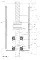
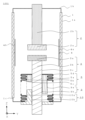
- FIG. 1 is a schematic cross-sectional view of a vacuum interrupter according to a first embodiment.
- 4 is a flowchart showing a manufacturing process of the bellows according to the first embodiment.
- 5A to 5C are schematic diagrams illustrating a process for producing a multilayer cylindrical body according to the first embodiment.
- 5A to 5C are schematic cross-sectional views illustrating a process for producing a bellows shape of the bellows according to the first embodiment.
- 4 is a schematic cross-sectional view illustrating a process of sealing between layers at both ends of the multi-layer bellows of embodiment 1.
- FIG. 4 is a flowchart showing an assembly process of the vacuum interrupter of the first embodiment.
- 11 is a schematic cross-sectional view of a vacuum interrupter according to a second embodiment.
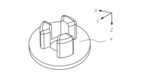
- FIG. 11 is a perspective view of a first guide according to a second embodiment.
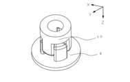
- FIG. 11 is a perspective view of a second guide according to the second embodiment.
- FIG. 11 is a perspective view of a first guide and a second guide according to a second embodiment.
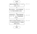
- 10 is a flowchart showing an assembly process of the vacuum interrupter of the second embodiment.
- 11 is a schematic cross-sectional view of a vacuum interrupter according to a third embodiment.
- FIG. FIG. 11 is a schematic cross-sectional view of a bellows according to a third embodiment.
- FIG. 11 is a perspective view of a divided body of a ring according to a third embodiment.
- 11 is a flowchart showing an assembly process of the vacuum interrupter of the third embodiment.
- the coordinate axes of the XYZ Cartesian coordinate system are shown in the diagram.
- the direction in which the movable electrode 3 is driven is the Z-axis direction
- the direction in which the movable electrode 3 approaches the fixed electrode 2 is the +Z-axis direction
- the direction in which it moves away is the -Z-axis direction.
- the direction from the fixed electrode 2 toward the shield 4 is the Y-axis direction
- the direction from the fixed electrode 2 toward the shield 4a is the +Y-axis direction
- the direction from the fixed electrode 2 toward the shield 4b is the -Y-axis direction.
- the direction from the back to the front is the +X-axis direction
- the direction from the front to the back is the -X-axis direction.
- FIG. 1 is a schematic cross-sectional view of the vacuum valve 100 in accordance with the first embodiment.
- the vacuum valve 100 includes an insulating container 1, a fixed electrode 2, a movable electrode 3, a bellows 5, and a shield 4.
- the insulating container 1 has a cylindrical container 1a made of ceramics or the like, and a fixed end plate 1b and a movable end plate 1c provided at both ends of the cylindrical container 1a.
- the fixed end plate 1b and the movable end plate 1c are brazed to the cylindrical container 1a, and the inside of the insulating container 1 is maintained in a vacuum.
- the insulating container 1 has a fixed electrode 2 and a movable electrode 3 at both ends, and has a shield 4 and a bellows 5 inside.
- the shield 4 is arranged to surround the fixed electrode 2 and the movable electrode 3, and protects the inner surface of the insulating container 1.
- the fixed electrode 2 has a fixed contact 2a and a fixed electrode rod 2b.
- the fixed contact 2a is joined to the end of the fixed electrode rod 2b.
- the fixed electrode rod 2b is fixed to the insulating container 1 via the fixed end plate 1b.
- the movable electrode 3 has a movable contact 3a and a movable electrode rod 3b.
- the movable contact 3a is joined to the end of the movable electrode bar 3b and is arranged so that it can be brought into contact with and separated from the fixed contact 2a.
- One end of the bellows 5 is joined to the movable end plate 1c and the other end is joined to the movable electrode bar 3b.
- the movable electrode 3 is joined to an operating mechanism (not shown) outside the insulating container 1. This allows the vacuum valve 100 to be opened and closed while maintaining the degree of vacuum inside the insulating container 1.
- the bellows 5 has a bellows structure that can expand and contract in the Z-axis direction, which is the driving direction of the movable electrode bar 3b. It is preferable that the bellows 5 has a multi-layer structure. In this case, the layer 5a on the innermost diameter side of the bellows 5 is the layer closest to the movable electrode bar 3b in the multi-layer structure.
- the bellows 5 also has a valley portion 5b of the bellows structure and a abdomen portion 5c, which is the portion other than the valley portion of the bellows structure. The bellows 5 is arranged so that the valley portion 5b of the bellows structure in the innermost diameter side layer 5a contacts the movable electrode bar 3b.
- the valley portion 5b of the bellows structure it is not necessary for the entire circumference of the valley portion 5b of the bellows structure to contact the movable electrode bar 3b. In other words, it is sufficient for only a portion of the valley portion 5b of the bellows structure to contact the movable electrode bar 3b. This suppresses buckling displacement of the bellows 5 in the XY plane direction.
- the valley 5b of the bellows structure in the innermost layer 5a comes into contact with the movable electrode rod 3b, friction occurs between the valley 5b of the bellows structure and the movable electrode rod 3b when the vacuum valve 100 is opened or closed. This reduces the transient vibration of the bellows 5 and improves the fatigue strength of the bellows 5.
- the bellows 5 has a multi-layer structure.
- the multi-layer structure of the bellows 5 may be structured such that the layers are sealed at both ends, and the layers are not sealed except at both ends of the multi-layer structure.
- vacuum leakage can be prevented unless a crack occurs in any of the layers of the multi-layer structure. This can improve the opening and closing life of the vacuum valve 100.
- the multi-layer structure of the bellows 5 is not sealed except at both ends, it is structured such that slippage occurs between the layers. This can reduce transient vibrations of the bellows 5 and improve the fatigue strength of the bellows 5.
- At least one of the valley portion 5b of the bellows structure of the innermost layer 5a of the bellows 5 and the outer periphery 3c of the movable electrode rod 3b may be coated with an insulating material.
- a resin part or the like may be sandwiched between the movable end plate 1c and the current-carrying part. This makes it possible to prevent the interruption current from flowing through the bellows 5 when the vacuum valve 100 is opened to interrupt the current.
- the movable electrode bar 3b in FIG. 1 is a cylinder, it may be a rectangular column. Even in this case, the bellows 5 is positioned so that the valley portion 5b of the bellows structure in the innermost layer 5a is in contact with the movable electrode bar 3b.
- FIG. 2 is a flow chart showing the steps of producing the bellows of the first embodiment.
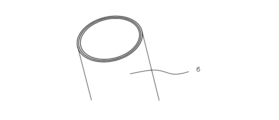
- Figure 3 is a schematic diagram showing the steps of producing the multilayered cylindrical body of the first embodiment.
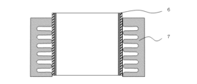
- Figure 4 is a schematic cross-sectional view showing the steps of producing the bellows shape of the bellows of the first embodiment.
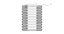
- Figure 5 is a schematic cross-sectional view showing the steps of sealing between the layers at both ends of the multilayered bellows of the first embodiment.
- step S101 a plurality of cylindrical bodies having different diameters are fitted together to produce a multi-layered cylindrical body 6.
- Fig. 3 shows the steps of producing a two-layered cylindrical body, a three-layered or more cylindrical body may be produced.
- step S102 the multi-layered cylindrical body 6 is inserted into a cavity of a die 7, and the side wall of the multi-layered cylindrical body 6 is hydraulically formed into a bellows shape.
- the die 7 has a cavity capable of housing the cylindrical body therein.
- the cavity also has an inner wall carved into a wave shape. This makes it possible to manufacture a multi-layered bellows 5 having a bellows structure.
- step S103 the spaces between the layers of the multi-layered bellows 5 are not sealed apart from the two end portions 8, but are sealed between the layers at the two end portions 8 by brazing. This completes the process for producing the bellows 5 in the first embodiment.
- Fig. 6 is a flow chart showing the assembly process of the vacuum interrupter of the first embodiment.
- the shield 4 is attached to the inside of a cylindrical container 1a made of ceramics or the like.
- the fixed contact 2a, the fixed electrode bar 2b, and the fixed end plate 1b are brazed together.
- the movable contact 3a, the movable electrode bar 3b, the bellows 5, and the movable end plate 1c are brazed together.
- the bellows 5 is arranged so that the valley portion 5b of the bellows structure in the innermost layer 5a contacts the movable electrode bar 3b.
- step S114 the fixed end plate 1b and the movable end plate 1c are brazed to both ends of the cylindrical container 1a, respectively.
- the movable contact 3a is disposed so as to be movable toward and away from the fixed contact 2a. This completes the assembly process of the vacuum interrupter 100 in the first embodiment.
- the valley portion 5b of the bellows structure in the innermost layer 5a of the bellows 5 is arranged so as to contact the movable electrode bar 3b.
- the multi-layer structure of the bellows 5 may be such that the layers are sealed at both ends, and the layers are not sealed except at both ends. With the above configuration, vacuum leakage can be prevented unless a tear occurs in all layers of the multi-layer structure. For example, even if the valley portion 5b of the bellows structure in the innermost layer 5a is worn away by friction with the movable electrode rod 3b and a tear occurs in the valley portion 5b of the bellows structure in the innermost layer 5a, the layers are sealed at both ends of the bellows 5, so that vacuum leakage from the gaps between the layers can be prevented. This can improve the opening and closing life of the vacuum valve 100. Furthermore, the multi-layer structure of the bellows 5 is such that the layers are not sealed except at both ends, so that slippage occurs between the layers. This can reduce transient vibration of the bellows 5 and improve the fatigue strength of the bellows 5.
- At least one of the valley portion 5b of the bellows structure of the innermost layer 5a and the outer periphery 3c of the movable electrode rod 3b may be coated with an insulating material.
- the movable electrode bar 3b in FIG. 1 may be a rectangular column. Even in this case, the bellows 5 is arranged so that the valley portion 5b of the bellows structure in the innermost layer 5a is in contact with the movable electrode bar 3b. This provides the same effect of suppressing buckling displacement of the bellows 5 in the XY plane direction.
- the manufacturing method of the vacuum valve 100 in the first embodiment includes the steps of fitting together a plurality of cylindrical bodies with different diameters to manufacture a multi-layered cylindrical body 6, forming the side walls of the multi-layered cylindrical body into a bellows shape to manufacture a multi-layered bellows 5 having a bellows structure, sealing the spaces between the layers at both ends 8 of the multi-layered bellows 5, and arranging the bellows 5 so that the valleys 5b of the bellows structure of the multi-layered bellows 5 come into contact with the movable electrode bar 3b.
- the above manufacturing method also allows the manufacture of a bellows 5 that has a multi-layered structure and in which the spaces between the layers at both ends 8 are sealed. This prevents vacuum leakage unless a tear occurs in any of the layers of the multi-layered structure of the bellows 5.
- the bellows 5 is described as having a multi-layer structure, but it may have a single-layer structure. Even in this case, the bellows 5 is arranged so that the valley portion 5b of the bellows structure is in contact with the movable electrode bar 3b. This provides the same effect of preventing the bellows 5 from buckling and displacing in the XY plane.
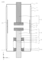
- FIG. 7 is a schematic cross-sectional view of the vacuum valve 101 in the second embodiment.
- the vacuum valve 100 in the first embodiment is characterized in that the valley portion 5b of the bellows structure in the innermost layer 5a of the bellows 5 is arranged so as to contact the movable electrode bar 3b.
- the vacuum valve 101 in the second embodiment is different from the vacuum valve 100 in the first embodiment in that it includes a first guide 9 and a second guide 10, and that the valley portion 5b of the bellows structure in the innermost layer 5a of the bellows 5 is arranged so as to contact at least one of the outer periphery 9a of the first guide 9 and the outer periphery 10a of the second guide 10.
- the same reference numerals are used for the same configurations as in the first embodiment.
- the first guide 9 is joined to the other end of the bellows 5.
- the outer periphery 9a of the first guide 9 is positioned so as to contact the valley portion 5b of the bellows structure in the innermost layer 5a of the bellows 5.
- the inner periphery 9b of the first guide 9 is positioned so as to contact the movable electrode bar 3b.
- the second guide 10 is joined to the movable end plate 1c.
- the outer periphery 10a of the second guide 10 is positioned so as to contact the valley portion 5b of the bellows structure in the innermost layer 5a of the bellows 5.
- the inner periphery 10b of the second guide 10 is positioned so as to contact the movable electrode bar 3b.
- FIG. 8 is a perspective view of the first guide 9 of embodiment 2
- FIG. 9 is a perspective view of the second guide 10 of embodiment 2
- FIG. 10 is a perspective view of the first guide 9 and the second guide 10 of embodiment 2.
- the first guide 9 and the second guide 10 have protrusions that can be fitted into each other.
- the first guide 9 and the second guide 10 are arranged so that the protrusions can be fitted into each other.
- first guide 9 and the second guide 10 are arranged so that at least one of the outer periphery 9a of the first guide 9 and the outer periphery 10a of the second guide 10 contacts the valley portion 5b of the bellows structure in the innermost layer 5a of the bellows 5. This prevents the bellows 5 from buckling and displacing in the XY plane.
- the entire circumference of the valley portion 5b of the bellows structure does not have to be in contact with the first guide 9 and the second guide 10. In other words, it is sufficient that a portion of the valley portion 5b of the bellows structure is in contact with at least one of the first guide 9 and the second guide 10.
- the material of the first guide 9 and the second guide 10 be an insulating material such as a resin material, and that the bellows 5 is structured so that no current flows through it.
- the vacuum valve 101 has a structure in which a resin part or the like is sandwiched between the movable end plate 1c and the current-carrying part.
- the vacuum valve 101 has a structure in which the outer periphery 9a of the first guide 9, the outer periphery 10a of the second guide 10, and the movable end plate 1c, which come into contact with the bellows 5, are insulated from one another. This makes it possible to prevent the interruption current from flowing through the bellows 5 when the vacuum valve 101 is opened to interrupt the current.
- the manufacturing process for the bellows 5 is the same as the manufacturing process for the bellows 5 in the first embodiment.
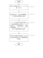
- Fig. 11 is a flow chart showing the assembly process of the vacuum interrupter according to the second embodiment.
- the shield 4 is attached to the inside of a cylindrical container 1a made of ceramics or the like.
- the fixed contact 2a, the fixed electrode bar 2b, and the fixed end plate 1b are brazed together.
- the movable contact 3a, the movable electrode bar 3b, the bellows 5, and the movable end plate 1c are brazed together.
- the bellows 5 is arranged so that the valley portion 5b of the bellows structure in the innermost layer 5a contacts the movable electrode bar 3b.
- steps S211 to S213 is not limited to the above, and may be changed or may be performed simultaneously.
- step S214 the fixed end plate 1b and the movable end plate 1c are brazed to both ends of the cylindrical container 1a.
- the movable contact 3a is arranged so as to be movable toward and away from the fixed contact 2a.
- step S215 the first guide 9 is attached to the other end of the bellows 5, and the second guide 10 is attached to the movable end plate 1c.
- step S215 the first guide 9 and the second guide 10 are positioned so that at least one of the outer periphery 9a of the first guide 9 and the outer periphery 10a of the guide 10 contacts the valley portion 5b of the bellows structure in the innermost layer 5a of the bellows 5. This completes the assembly process of the vacuum interrupter 101 in the second embodiment.
- the vacuum valve 101 in embodiment 2 has a first guide 9 and a second guide 10.
- the first guide 9 is joined to the other end of the bellows 5, and the outer periphery 9a of the first guide 9 contacts the valley portion 5b of the bellows structure of the bellows 5, the inner periphery 9b contacts the movable electrode bar 3b, and has a protrusion.
- the second guide 10 is joined to the movable end plate 1c, and the outer periphery 10a of the second guide 10 contacts the valley portion 5b of the bellows structure of the bellows 5, the inner periphery 10b of the second guide 10 contacts the movable electrode bar 3b, and has a protrusion that can be fitted into the first guide 9. This prevents the bellows 5 from buckling and displacing in the XY plane.
- the first guide 9 or the second guide 10 comes into contact with the valley portion 5b of the bellows structure when the vacuum valve 101 is opened or closed, thereby reducing transient vibration of the bellows 5.
- This improves the opening and closing life of the vacuum valve 101 compared to a configuration in which the vacuum valve 101 is configured with only either the first guide 9 or the second guide 10.
- the first guide 9 and the second guide 10 may also be made of an insulating material such as a resin material.
- first guide 9 and the second guide 10 may be made of a material that reduces wear when sliding against the bellows 5 compared to when the first guide 9 and the second guide 10 are made of metal.
- wear on the bellows 5 due to sliding friction is reduced, and the occurrence of cracks in the valleys 5b of the bellows structure is suppressed. This makes it easier to apply a single-layer bellows 5. This reduces the size of the bellows 5, and therefore the size of the vacuum valve 101 can be reduced.
- the manufacturing method of the vacuum valve 101 in the second embodiment includes the steps of fitting together a plurality of cylindrical bodies of different diameters to produce a multi-layered cylindrical body 6, forming the side walls of the multi-layered cylindrical body into a bellows shape to produce a multi-layered bellows 5 having a bellows structure, sealing the spaces between the layers at both ends 8 of the multi-layered bellows 5, and arranging the outer periphery 9a of the first guide 9 and the outer periphery 10a of the second guide 10 so that at least one of them contacts the valley 5b of the bellows structure in the innermost layer 5a of the bellows 5.
- the valley 5b of the bellows structure of the bellows 5 contacts at least one of the outer periphery 9a of the first guide 9 and the outer periphery 10a of the second guide 10, so that the vacuum valve 101 can be manufactured that can suppress buckling displacement of the bellows 5.
- the above manufacturing method also allows the manufacture of a bellows 5 that has a multi-layered structure and in which the spaces between the layers at both ends 8 are sealed. This makes it possible to prevent vacuum leakage unless a crack occurs in any of the layers of the multi-layer structure of the bellows 5.
- the bellows 5 in the second embodiment has been described as having a multi-layer structure, it may have a single-layer structure. Even in this case, the bellows 5 is arranged so that at least one of the outer periphery 9a of the first guide 9 and the outer periphery 10a of the second guide 10 contacts the valley portion 5b of the bellows structure of the bellows 5. This provides the same effect of suppressing buckling displacement of the bellows 5 in the XY plane direction.
- the movable electrode bar 3b in FIG. 7 is a cylinder, it may be a rectangular prism.
- the cross sections of the inner periphery 9b of the first guide 9 and the inner periphery 10b of the second guide 10 have the same polygonal shape as the cross section of the rectangular prism.
- the cross sections of the outer periphery 9a of the first guide 9 and the outer periphery 10a of the second guide 10 may be polygonal. Even in this case, the first guide 9 and the second guide 10 are arranged so that at least one of the outer periphery 9a of the first guide 9 and the outer periphery 10a of the second guide 10 contacts the valley portion 5b of the bellows structure in the innermost layer 5a of the bellows 5. This provides the same effect of suppressing buckling displacement of the bellows 5 in the XY plane direction.
- FIG. 12 is a schematic cross-sectional view of the vacuum valve 102 in the third embodiment.
- the vacuum valve 100 in the first embodiment is characterized in that the valley 5b of the bellows structure in the innermost layer 5a of the bellows 5 is arranged so as to contact the movable electrode bar 3b.
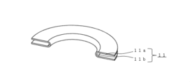
- the vacuum valve 102 in the third embodiment includes a thin ring 11 having a U-shaped cross section.
- the ring 11 is not limited to an annular shape, and may be a divided ring shape as shown in FIG. 14. In the following, the ring 11 is used as a general term for an annular ring and a divided body of an annular ring.
- the vacuum valve 102 in the third embodiment is different from the vacuum valve 100 in the first embodiment in that the ring 11 is inserted into the valley 5b of the bellows structure in the outermost layer 5d of the bellows 5.
- the same components as those in the first embodiment are designated by the same reference numerals.
- FIG. 13 is a schematic cross-sectional view of the bellows 5 of the third embodiment.
- FIG. 14 is a perspective view of a divided body of the ring 11 of the third embodiment. As shown in FIG. 14, the ring 11 is a thin plate and has a U-shaped cross section. The ring 11 is inserted into the valley portion 5b of the bellows structure in the layer 5d on the outermost diameter side of the bellows 5. This reinforces the bellows 5 with the ring 11, increasing the rigidity of the bellows 5 and suppressing buckling displacement of the bellows 5 in the XY plane.
- the ring 11 is joined to the outermost layer 5d at the abdomen 11a, which corresponds to the side of the U-shape of the ring 11, and is not joined to the outermost layer 5d at the R portion 11b, which corresponds to the valley of the U-shape of the ring 11.
- the manufacturing process for the bellows 5 is the same as the manufacturing process for the bellows 5 in the first embodiment.
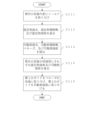
- Fig. 15 is a flow chart showing the assembly process of the vacuum interrupter according to the third embodiment.
- the shield 4 is attached to the inside of a cylindrical container 1a made of ceramics or the like.
- the fixed contact 2a, the fixed electrode bar 2b, and the fixed end plate 1b are brazed together.
- the ring 11 is inserted into the valley portion 5b of the bellows structure in the outermost layer 5d of the bellows 5, and the movable contact 3a, the movable electrode rod 3b, the bellows 5, the ring 11 and the movable end plate 1c are brazed together.
- steps S311 to S313 is not limited to the above-mentioned order, and the order may be changed or steps may be performed simultaneously.
- step S314 the fixed end plate 1b and the movable end plate 1c are brazed to both ends of the cylindrical container 1a, respectively.
- the movable contact 3a is disposed so as to be movable toward and away from the fixed contact 2a. This completes the assembly process of the vacuum interrupter 102 in the third embodiment.
- the vacuum valve 102 in this embodiment has a ring 11 inserted into the valley portion 5b of the bellows structure in the layer 5d on the outermost diameter side of the bellows 5. This reinforces the bellows 5 with the ring 11, increasing the rigidity of the bellows 5 and suppressing buckling displacement of the bellows 5 in the XY plane direction. Furthermore, with the above configuration, it is possible to reduce transient vibrations of the bellows 5 and improve the fatigue strength of the bellows 5.
- the ring 11 has a structure in which the abdomen 11a of the ring 11 is joined to the outermost layer 5d, and the R portion 11b of the ring 11 is not joined to the outermost layer 5d.
- This makes it possible to suppress an increase in the thickness of the bellows 5 compared to when the ring 11 is joined to the outermost layer 5d at the R portion 11b of the ring 11.
- it is possible to suppress an increase in bending stress in the valley portion 5b of the bellows structure of the bellows 5 during the opening and closing operation of the vacuum valve 102. This makes it possible to improve the fatigue life of the bellows 5.
- the R portion 11b of the ring 11 and the layer 5d on the outermost diameter side may be structured so as not to come into contact with each other. Even in this case, the ring 11 reinforces the bellows 5, increasing the rigidity of the bellows 5, and thus provides the same effect of suppressing buckling displacement of the bellows 5 in the XY plane direction.
- the manufacturing method of the vacuum valve 102 in this embodiment includes the steps of fitting together a plurality of cylindrical bodies of different diameters to produce a multi-layered cylindrical body 6, forming the side walls of the multi-layered cylindrical body into a bellows shape to produce a multi-layered bellows 5 having a bellows structure, sealing the gaps between the layers at both ends 8 of the multi-layered bellows 5, and inserting the ring 11 or a divided body of the ring 11 into the valley 5b of the bellows structure in the outermost layer 5d of the bellows 5.
- the bellows 5 is reinforced by the ring 11, so that the vacuum valve 102 capable of suppressing buckling displacement of the bellows 5 can be manufactured.
- the above manufacturing method also makes it possible to manufacture a bellows 5 having a multi-layered structure and in which the gaps between the layers at both ends 8 are sealed. As a result, vacuum leakage can be prevented unless a tear occurs in all layers of the multi-layered structure of the bellows 5.
- the bellows 5 is described as having a multi-layer structure, but it may have a single-layer structure. Even in this case, the ring 11 is inserted into the valley portion 5b of the bellows structure. This provides the same effect of preventing the bellows 5 from buckling and displacing in the XY plane.
- the divided bodies of the ring 11 in FIG. 12 are described as ring 11 divided into two, the number of divisions is not limited to one. In other words, a divided body of the ring 11 divided two or more times may be inserted into the valley portion 5b of the bellows structure in the layer 5d on the outermost diameter side. Even in this case, the same effect of suppressing buckling displacement of the bellows 5 in the XY plane direction is achieved.
- the ring 11 does not have to be inserted into all of the valleys 5b of the bellows structure in the outermost layer 5d of the bellows 5.
- the ring 11 may be inserted into the valleys 5b of the bellows structure at both ends of the bellows 5 that have a large expansion and contraction range in the Z-axis direction, which is the driving direction of the movable electrode bar 3b, or in the center of the bellows 5 where buckling is likely to occur.
- rings 11 it is not necessary for all the rings 11 to have the same plate thickness.
- thicker rings 11 may be inserted in the valleys 5b of the bellows structure at both ends of the bellows 5 where the expansion and contraction width in the Z-axis direction, which is the driving direction of the movable electrode bar 3b, is large, or in the center of the bellows 5 where buckling is likely to occur.
- rings 11 that are thinner than the rings 11 inserted at both ends and the center of the bellows 5 may be inserted in places other than both ends and the center of the bellows 5.
Landscapes
- Engineering & Computer Science (AREA)
- Power Engineering (AREA)
- High-Tension Arc-Extinguishing Switches Without Spraying Means (AREA)
Abstract
Dans une soupape à vide (100, 101), une section de vallée (5b) de la structure en accordéon d'un soufflet (5) entre en contact avec une tige d'électrode côté mobile (3b) ou un guide (9, 10). En variante, dans une soupape à vide (102), une bague mince (11) présentant une section transversale en forme de U ou un segment annulaire (11) est insérée dans la section de vallée (5b) de la structure en accordéon du soufflet (5). Ceci permet de fournir une soupape à vide (100, 101, 102) dans laquelle le déplacement de déformation du soufflet (5) peut être supprimé, ainsi qu'un procédé de fabrication de la soupape à vide (100, 101, 102).
Priority Applications (2)
| Application Number | Priority Date | Filing Date | Title |
|---|---|---|---|
| JP2025541206A JPWO2025041252A1 (fr) | 2023-08-22 | 2023-08-22 | |
| PCT/JP2023/030107 WO2025041252A1 (fr) | 2023-08-22 | 2023-08-22 | Soupape à vide et procédé de fabrication de soupape à vide |
Applications Claiming Priority (1)
| Application Number | Priority Date | Filing Date | Title |
|---|---|---|---|
| PCT/JP2023/030107 WO2025041252A1 (fr) | 2023-08-22 | 2023-08-22 | Soupape à vide et procédé de fabrication de soupape à vide |
Publications (1)
| Publication Number | Publication Date |
|---|---|
| WO2025041252A1 true WO2025041252A1 (fr) | 2025-02-27 |
Family
ID=94731840
Family Applications (1)
| Application Number | Title | Priority Date | Filing Date |
|---|---|---|---|
| PCT/JP2023/030107 Pending WO2025041252A1 (fr) | 2023-08-22 | 2023-08-22 | Soupape à vide et procédé de fabrication de soupape à vide |
Country Status (2)
| Country | Link |
|---|---|
| JP (1) | JPWO2025041252A1 (fr) |
| WO (1) | WO2025041252A1 (fr) |
Citations (9)
| Publication number | Priority date | Publication date | Assignee | Title |
|---|---|---|---|---|
| JPS5090159U (fr) * | 1973-12-19 | 1975-07-30 | ||
| JPS5363578A (en) * | 1976-11-19 | 1978-06-07 | Tokyo Shibaura Electric Co | Vacuum valve |
| JPS5371771U (fr) * | 1976-11-19 | 1978-06-15 | ||
| JPS54101364U (fr) * | 1979-01-22 | 1979-07-17 | ||
| JPS5956331A (ja) * | 1982-09-24 | 1984-03-31 | 富士電機株式会社 | 真空バルブ |
| JPS61121221A (ja) * | 1984-11-17 | 1986-06-09 | 株式会社明電舎 | 真空インタラプタ |
| DE19735479A1 (de) * | 1997-08-16 | 1999-02-18 | Abb Patent Gmbh | Vakuumschaltkammer |
| WO2012157397A1 (fr) * | 2011-05-18 | 2012-11-22 | 株式会社明電舎 | Soufflets et leur procédé de fabrication |
| JP2013229149A (ja) * | 2012-04-25 | 2013-11-07 | Mitsubishi Electric Corp | 真空バルブ |
-
2023
- 2023-08-22 WO PCT/JP2023/030107 patent/WO2025041252A1/fr active Pending
- 2023-08-22 JP JP2025541206A patent/JPWO2025041252A1/ja active Pending
Patent Citations (9)
| Publication number | Priority date | Publication date | Assignee | Title |
|---|---|---|---|---|
| JPS5090159U (fr) * | 1973-12-19 | 1975-07-30 | ||
| JPS5363578A (en) * | 1976-11-19 | 1978-06-07 | Tokyo Shibaura Electric Co | Vacuum valve |
| JPS5371771U (fr) * | 1976-11-19 | 1978-06-15 | ||
| JPS54101364U (fr) * | 1979-01-22 | 1979-07-17 | ||
| JPS5956331A (ja) * | 1982-09-24 | 1984-03-31 | 富士電機株式会社 | 真空バルブ |
| JPS61121221A (ja) * | 1984-11-17 | 1986-06-09 | 株式会社明電舎 | 真空インタラプタ |
| DE19735479A1 (de) * | 1997-08-16 | 1999-02-18 | Abb Patent Gmbh | Vakuumschaltkammer |
| WO2012157397A1 (fr) * | 2011-05-18 | 2012-11-22 | 株式会社明電舎 | Soufflets et leur procédé de fabrication |
| JP2013229149A (ja) * | 2012-04-25 | 2013-11-07 | Mitsubishi Electric Corp | 真空バルブ |
Also Published As
| Publication number | Publication date |
|---|---|
| JPWO2025041252A1 (fr) | 2025-02-27 |
Similar Documents
| Publication | Publication Date | Title |
|---|---|---|
| CN1103007C (zh) | 嵌套的桥式密封 | |
| US5630593A (en) | Pressure-energized sealing rings | |
| CN1277651A (zh) | C形密封环 | |
| WO2022007892A1 (fr) | Ensemble tuyau ondulé, interrupteur à vide et disjoncteur à vide | |
| WO2025041252A1 (fr) | Soupape à vide et procédé de fabrication de soupape à vide | |
| EP3798484B1 (fr) | Dispositif de joint d'étanchéité | |
| JPH07174233A (ja) | ベローズ | |
| KR20000022795A (ko) | 진동 디커플러 장치 | |
| US4570747A (en) | Mechanical lock joint for joining tubular products | |
| CN113678219B (zh) | 真空阀 | |
| CN115111063B (zh) | 馈通组件 | |
| US6308857B1 (en) | Vacuum chamber | |
| US11942289B2 (en) | Vacuum interrupter and vacuum breaker | |
| JP2023154158A (ja) | 真空バルブ | |
| EP2551877A1 (fr) | Vanne de dépression et appareillage de commutation dans lequel est montée cette vanne de dépression | |
| JP2003317583A (ja) | 真空バルブ | |
| JP2022500602A (ja) | ベローズ型アキュムレータ | |
| JP6652298B2 (ja) | 真空バルブ | |
| WO1997018408A2 (fr) | Construction de soufflet en sandwich | |
| CN113541032B (zh) | 用于间歇和部分旋转和平移轴的密封结构 | |
| JP2006017255A (ja) | シール機構 | |
| CN121844404A (zh) | 真空开关管和真空开关 | |
| KR100372412B1 (ko) | 오일링의 구조 | |
| JP7446524B2 (ja) | 真空バルブ | |
| JP2020115032A (ja) | 弁装置 |
Legal Events
| Date | Code | Title | Description |
|---|---|---|---|
| 121 | Ep: the epo has been informed by wipo that ep was designated in this application |
Ref document number: 23949713 Country of ref document: EP Kind code of ref document: A1 |
|
| ENP | Entry into the national phase |
Ref document number: 2025541206 Country of ref document: JP Kind code of ref document: A |
|
| WWE | Wipo information: entry into national phase |
Ref document number: 2025541206 Country of ref document: JP |
|
| NENP | Non-entry into the national phase |
Ref country code: DE |