WO2025041250A1 - ロボットの制御装置、制御方法およびロボットシステム - Google Patents
ロボットの制御装置、制御方法およびロボットシステム Download PDFInfo
- Publication number
- WO2025041250A1 WO2025041250A1 PCT/JP2023/030098 JP2023030098W WO2025041250A1 WO 2025041250 A1 WO2025041250 A1 WO 2025041250A1 JP 2023030098 W JP2023030098 W JP 2023030098W WO 2025041250 A1 WO2025041250 A1 WO 2025041250A1
- Authority
- WO
- WIPO (PCT)
- Prior art keywords
- robot
- filament
- control device
- movable members
- length
- Prior art date
- Legal status (The legal status is an assumption and is not a legal conclusion. Google has not performed a legal analysis and makes no representation as to the accuracy of the status listed.)
- Pending
Links
Images


Classifications
-
- B—PERFORMING OPERATIONS; TRANSPORTING
- B25—HAND TOOLS; PORTABLE POWER-DRIVEN TOOLS; MANIPULATORS
- B25J—MANIPULATORS; CHAMBERS PROVIDED WITH MANIPULATION DEVICES
- B25J19/00—Accessories fitted to manipulators, e.g. for monitoring, for viewing; Safety devices combined with or specially adapted for use in connection with manipulators
- B25J19/0025—Means for supplying energy to the end effector
-
- B—PERFORMING OPERATIONS; TRANSPORTING
- B25—HAND TOOLS; PORTABLE POWER-DRIVEN TOOLS; MANIPULATORS
- B25J—MANIPULATORS; CHAMBERS PROVIDED WITH MANIPULATION DEVICES
- B25J13/00—Controls for manipulators
- B25J13/08—Controls for manipulators by means of sensing devices, e.g. viewing or touching devices
- B25J13/085—Force or torque sensors
-
- B—PERFORMING OPERATIONS; TRANSPORTING
- B25—HAND TOOLS; PORTABLE POWER-DRIVEN TOOLS; MANIPULATORS
- B25J—MANIPULATORS; CHAMBERS PROVIDED WITH MANIPULATION DEVICES
- B25J9/00—Program-controlled manipulators
- B25J9/16—Program controls
- B25J9/1628—Program controls characterised by the control loop
- B25J9/1633—Program controls characterised by the control loop compliant, force, torque control, e.g. combined with position control
-
- B—PERFORMING OPERATIONS; TRANSPORTING
- B25—HAND TOOLS; PORTABLE POWER-DRIVEN TOOLS; MANIPULATORS
- B25J—MANIPULATORS; CHAMBERS PROVIDED WITH MANIPULATION DEVICES
- B25J9/00—Program-controlled manipulators
- B25J9/16—Program controls
- B25J9/1628—Program controls characterised by the control loop
- B25J9/1638—Program controls characterised by the control loop compensation for arm bending/inertia, pay load weight/inertia
Definitions
- This disclosure relates to a robot control device, a control method, and a robot system.
- a control device that controls a robot having a robot arm with multiple joints and a linear body attached along the side of the robot arm (see, for example, Patent Document 1).
- the control device as described above estimates the force acting on the robot arm and controls the robot based on the estimated force.
- the mass of the filament acts as a load on the robot arm, so the force estimated by the control device contains an error, and the robot cannot be controlled with high precision. Therefore, it is desirable to be able to precisely control a robot having a filament attached to a robot arm.
- One aspect of the present disclosure is a control device for controlling a robot having multiple movable members, the control device for the robot having at least one processor, the processor acquiring the mass of a filament that is retrofitted to the robot, and setting the acquired mass of the filament as the load acting on each of the movable members.
- FIG. 1 is a side view illustrating a robot system according to an embodiment of the present disclosure.
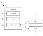
- FIG. 2 is a block diagram showing a configuration of a control device according to an embodiment of the present disclosure.
- 4 is a flowchart illustrating a control method according to an embodiment of the present disclosure.
- FIG. 11 is a schematic diagram for explaining an example of a control method according to an embodiment of the present disclosure.
- a control device 10 and a robot system 100 will be described below with reference to the drawings.
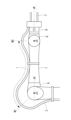
- a robot system 100 according to this embodiment includes a robot 1 and a control device 10 that controls the robot 1, as shown in FIG.
- the robot 1 is, for example, a six-axis articulated robot, and is a collaborative robot that works in collaboration with a worker.
- the robot 1 includes a base 3 placed on a horizontal floor surface F, and a rotating body 4 supported rotatably relative to the base 3 about a vertical first axis J1.
- the robot 1 also includes a plurality of arm members (movable members) and a wrist unit supported by the rotating body 4 and rotatably connected to each other.
- the robot 1 includes, as arm members, a first arm 5 supported rotatably relative to the rotating body 4 about a horizontal second axis J2, and a second arm 6 supported rotatably relative to the first arm 5 about a horizontal third axis J3.
- the wrist unit includes a first wrist element (movable member) 7 supported rotatably relative to the second arm 6 about a fourth axis J4 extending along a plane perpendicular to the third axis J3.
- the wrist unit includes a second wrist element (movable member) 8 supported rotatably relative to the first wrist element 7 about a fifth axis J5 perpendicular to the fourth axis J4.
- the wrist unit includes a third wrist element (movable member) 9 supported rotatably relative to the second wrist element 8 about a sixth axis J6 perpendicular to the fifth axis J5. That is, the robot 1 has six rotational joints A1 to A6 which rotate around the first axis J1 to the sixth axis J6, respectively.
- Each of the rotary joints A1 to A6 is driven by a motor (not shown) and a reducer that slows down the rotation of each motor.
- Each of the rotary joints A1 to A6 is also fitted with a six-axis force sensor (not shown) that detects the force acting on each joint shaft.
- a tool T is attached to the tip of the robot 1, i.e., the flange surface 9f provided on the third wrist element 9, by, for example, a user to whom the robot 1 is to be installed.
- the tool T is, for example, a hand equipped with a drive unit for gripping a workpiece or the like to be worked on.
- a line body 2 such as a cable for sending power and control signals to the tool T is also mounted on the robot 1 by a user or the like after the robot 1 is installed.
- the line body 2 is a bundle of these multiple cables using a conduit tube or the like.
- one end of the line body 2 is connected to the control device 10, and the other end is connected to the tool T.
- the filament 2 is attached to the outer surface of the robot 1, for example, with the robot 1 placed in the basic posture shown in Fig. 1.
- the basic posture of the robot 1 refers to, for example, a posture in which the third axis J3 is placed vertically above the second axis J2, the fifth axis J5 is placed parallel to and horizontally forward of the third axis J3, and the sixth axis J6 extends horizontally forward.
- the filament 2 extends from one end connected to the control device 10 located away from the robot 1 toward the base 3, and is raised upward at a position away from the base 3.
- the filament 2 then passes outside the rotational joints A1 and A2, is placed along the side of the first arm 5, and is fixed to the side of the first arm 5 by two fixing devices f1 and f2.
- the filament 2 is placed along the side of the first wrist element 7 and fixed to the side of the first wrist element 7 by the fixing device f3. Then, after passing outside the rotary joints A5 and A6, the other end of the filament 2 is connected to the tool T.
- the control device 10 includes an input device 11, at least one memory 12 such as a ROM or a RAM, and at least one processor 13 such as a CPU.
- the input device 11 is, for example, a combination of a display device such as a touch panel or a monitor with a keyboard, a mouse, push buttons, etc.
- the input device 11 accepts information about the tool T and the filament 2 input by a user or the like when setting conditions after the tool T and the filament 2 are attached to the robot 1.
- the memory 12 stores in advance the dimensions and center of gravity of each part of the robot 1 as initial settings.
- Examples of the dimensions of each part of the robot 1 include the distance L1 between the second axis J2 and third axis J3 of the first arm 5, and the distance L2 between the third axis J3 and fifth axis J5 of the second arm 6 and first wrist element 7.
- Another dimension is the distance L3 from the fifth axis J5 to the flange surface 9f.
- the center of gravity positions are the center position of dimension L1 on the longitudinal axis of the first arm 5, the center position of dimension L2 on the fourth axis J4, and the center position of dimension L3 on the sixth axis J6.
- the control device 10 has a function for setting the mass and center of gravity of attachment members and the like that are attached to the flange surface 9f.
- a user or the like uses this function to input the mass and center of gravity of a tool T that is attached to the flange surface 9f. This makes it possible to appropriately control the robot 1, taking into account the load acting on the robot 1 by the heavy object, even if a heavy object is attached to the flange surface 9f and the characteristics of the entire robot 1 change.
- control device 10 of the present disclosure has a function of setting the filament 2 connected to the tool T as a load. Specifically, the control device 10 stores in the memory 12 a setting program for setting the filament 2 as a load.
- a user or the like who has attached the filament 2 to the robot 1 starts a setting program stored in the memory 12, causing a predetermined user interface to be displayed on the screen of the input device 11.
- the user or the like then inputs, for example, the total weight (mass) of the filament 2 according to the displayed user interface.
- the processor 13 of the control device 10 divides the total weight into three weights based on the ratio L1:L2:L3 of the dimensions L1 to L3, which is stored as an initial setting value in the memory 12. The processor 13 then sets each of the three divided weights as a load acting on each center of gravity position, which is stored as an initial setting value in the memory 12.
- the weight ratio corresponding to dimension L1 is set as the load acting on the first arm 5 at the center of gravity of dimension L1.
- the weight ratio corresponding to dimension L2 is set as the load acting on the second arm 6 at the center of gravity of dimension L2.
- the weight ratio corresponding to dimension L3 is set as the load acting on the second wrist element 8 at the center of gravity of dimension L3.
- a total weight of the filament 2 is input to the input device 11 by a user or the like (step S1).
- the total weight of the filament 2 may be input together with the mass and center of gravity position of the tool T.
- the total weight of the filament 2 thus input is sent to the memory 12 together with the mass and center of gravity of the tool T and stored therein.
- the processor 13 reads out the dimensions L1 to L3 stored in the memory 12, and divides the input total weight of the filament 2 into three based on the ratio of the read out dimensions L1:L2:L3 (step S2).
- the processor 13 sets each of the three divided weights as the load acting on each movable member, i.e., the first arm 5, the second arm 6, and the second wrist element 8 (step S3).
- the total weight of the wire body 2 mounted on the robot 1 is distributed as a load corresponding to each movable member.
- control device 10 can detect contact between the robot 1 and an external object, etc., taking into account the load caused by the filament 2, for example.
- An example of a method for detecting contact when the control device 10 causes the robot 1 to perform a predetermined task will be described below.
- the processor 13 reads from the memory 12 and executes an operation program for making the robot 1 perform a specified task. As a result, the processor 13 rotates each of the motors of the rotary joints A1 to A6 of the robot 1 based on a plurality of operation commands contained in the operation program, and sequentially changes the posture of the robot 1.
- the processor 13 estimates the forces acting on the rotary joints A2, A3, and A5 based on the inertial forces acting on each movable member due to the movement and the weight (mass) of each movable member. The processor 13 then causes the robot 1 to perform the predetermined movement, acquires the detection values of the force sensors of the rotary joints A2, A3, and A5, and subtracts each estimated force from each acquired detection value.
- the processor 13 determines that a force greater than expected is acting on the robot 1, in other words, that the robot 1 is in contact with an external object or the like. If it determines that contact is occurring, it slows down or stops the movement of the robot 1. In this way, the control device 10 causes the robot 1 to perform a predetermined task while detecting contact with the robot 1.
- the processor 13 can take into account the effect of the load from the filament 2 attached to the robot 1 when estimating the forces acting on the rotational joints A2, A3, and A5. Therefore, the processor 13 can more accurately estimate the forces acting on the rotational joints A2, A3, and A5, and can prevent erroneous detection of contact of the robot 1.
- the load acting on the robot 1 by the filament 2 is calculated based on the dimensional ratio L1:L2:L3 pre-stored in the memory 12 and the total weight of the filament 2 input by the user, etc.
- the user, etc. does not need to input information regarding the length of the filament 2, and does not need to measure the length of the filament 2 corresponding to each movable member of the robot 1 when attaching the filament 2 to the robot 1, etc., thereby reducing the burden on the user, etc.
- the total weight of the filament 2 is set as the load acting on the robot 1, but instead, the weight of a portion of the filament 2 may be set as the load.
- the load can be set excluding the weight of the filament 2 between the end connected to the control device 10 and the contact point with the floor surface F, i.e., the weight of the part that does not actually act as a load on the robot 1. Therefore, the load setting for the robot 1 can be performed more accurately.
- the total weight of the filament 2 is divided according to the ratio of the dimensions L1, L2, and L3 corresponding to each movable member.
- the total weight of the filament 2 may be divided based on the values obtained by multiplying each of the dimensions L1, L2, and L3 by a coefficient greater than 1.
- the dimensions L1 and L2 corresponding to the excess length may be multiplied by a larger coefficient. This allows each of the dimensions L1, L2, and L3 to be weighted according to the extra length of the filament 2, making it possible to set a load with high accuracy that is more suited to the actual wiring configuration of the filament 2.
- the load from the filament 2 attached to the robot 1 is set to act on the center of gravity of each movable member of the robot 1.
- the position on which the load from the filament 2 acts may be set to any position input by the user, etc.
- the user may consider the wiring path of the filament 2 and set the center of gravity of the filament 2 in advance. In such a case, the user may input the center of gravity position that he or she has grasped in advance based on the wiring form of the filament 2 mounted on the robot 1 through the input device 11. This allows the load from the filament 2 to be set in accordance with the actual condition.
- the total weight of the filament 2 is distributed based on the dimensions L1 to L3 of each part of the robot 1.
- this may be input to estimate the load acting on each movable member based on the dimensions L1 to L3 stored in the memory 12.
- the user or the like inputs the mass per unit length of the filament 2 using the input device 11.
- the processor 13 multiplies each of the dimensions L1, L2, and L3 stored in the memory 12 by the input mass per unit length of the filament 2, and estimates each value obtained by multiplication as the load acting on each movable member.
- the magnitude of the load acting on each movable member may be estimated based on the measured length of each section.
- a user or the like actually measures the length of each section obtained by dividing the entire length of the filament 2 attached to the robot 1 according to the length of each movable member of the robot 1. Then, the user or the like inputs the actually measured length of each section into the input device 11 together with the mass per unit length of the filament 2.
- the processor 13 sets the load acting on each movable member to a value obtained by multiplying the input length of each section of the filament 2 by the input mass per unit length of the filament 2. This makes it possible to set the load acting on the robot 1 by the filament 2 more precisely.
- the midpoint in the longitudinal direction of the extra length may be measured as the section boundary of that section. That is, in the example shown in FIG. 4, since there is extra length on both sides of one section of the filament 2 corresponding to the second arm 6, it is sufficient to measure the length l along the filament 2 between midpoint M1 and midpoint M2 in the longitudinal direction of the extra length on both sides.
- the total weight of the filament 2 is input by the operator to the input device 11.
- the total weight of the filament 2 may be stored in advance in the memory 12 as an initial setting value.
- the rotary joints A2, A3, and A5 that drive the first arm 5, the second arm 6, and the second wrist element 8 are exemplified as rotary joints on which the mass of the filament 2 acts as a large load.
- the position of the center of gravity of the filament 2 can be set with high precision, it may be possible to set the load acting on the rotary joints A1, A4, and A6.
- control device 10 is described as controlling an articulated robot having six rotational joints A1 to A6, but the control target of the control device 10 is not limited to this.
- control device 10 may be applied to the control of a linear motion robot having at least one linear motion mechanism.
- control method according to this embodiment has been applied to contact detection of the robot 1, which is a collaborative robot
- the present invention is not limited to this and may be applied, for example, to the operation control of a robot 1 other than a collaborative robot.
- the load from the umbilical member 2 attached to the robot 1 significantly affects the dynamic characteristics of the robot 1. Therefore, by applying the control method according to this embodiment, it is possible to obtain the advantage that the robot 1 operating at high speed can be controlled more accurately.
- Appendix 1 A control device for controlling a robot having a plurality of movable members, A robot control device comprising at least one processor, the processor acquiring a mass of a filament that is retrofitted to the robot, and setting the acquired mass of the filament as a load acting on each of the movable members.
- Appendix 2 A control device as described in Appendix 1, comprising a memory for storing the length of each of the movable members, wherein the processor distributes the acquired mass of the filament as a load acting on each of the movable members in a proportion corresponding to the length of each of the movable members stored in the memory.
- Appendix 3 a memory for storing a length of each of the movable members, the processor A control device as described in Appendix 1, which calculates the load acting on each of the movable members by acquiring the mass per unit length of the filament and multiplying the acquired mass per unit length of the filament by a length corresponding to the length of each of the movable members stored in the memory.
- Appendix 4 A control device as described in Appendix 3, wherein the length corresponding to the length of each of the movable members stored in the memory is calculated by multiplying the length of each of the movable members stored in the memory by a coefficient greater than 1. (Appendix 5) 5.
- the control device detects interference between the robot and an object or person in the vicinity of the robot based on values including the mass of each of the movable members and a load acting on each of the movable members.
- Appendix 6 A robot system comprising the robot and the control device according to any one of Supplementary Note 1 to Supplementary Note 5.
- Appendix 7) A control method for controlling a robot having a plurality of movable members, the control method comprising: acquiring a mass of a filament that is retrofitted to the robot; and setting the acquired mass of the filament as a load acting on each of the movable members.
Landscapes
- Engineering & Computer Science (AREA)
- Robotics (AREA)
- Mechanical Engineering (AREA)
- Human Computer Interaction (AREA)
- Manipulator (AREA)
- Numerical Control (AREA)
Abstract
複数の可動部材を備えるロボット(1)を制御する制御装置(10)であって、少なくとも1つのプロセッサを備え、プロセッサが、ロボット(1)に後付けにより装着される線条体(2)の質量を取得し、取得した線条体(2)の質量を各可動部材(5),(6),(8)に作用する負荷として設定するロボットの制御装置(10)である。
Description
本開示は、ロボットの制御装置、制御方法およびロボットシステムに関するものである。
複数の関節部を有するロボットアームと、そのロボットアームの側面に沿うようにして装着された線条体とを備えるロボットを制御する制御装置が知られている(例えば、特許文献1参照。)。
上記のような制御装置は、ロボットアームに作用する力を推定し、その推定した力に基づいてロボットを制御する。しかし、ロボットアームに線条体が装着されている場合には、その線条体の質量が、ロボットアームに負荷として作用するため、制御装置が推定する力に誤差が含まれ、ロボットを精度よく制御できない。
したがって、ロボットアームに線条体が装着されたロボットを、精度良く制御できることが望まれている。
したがって、ロボットアームに線条体が装着されたロボットを、精度良く制御できることが望まれている。
本開示の一態様は、複数の可動部材を備えるロボットを制御する制御装置であって、少なくとも1つのプロセッサを備え、該プロセッサが、前記ロボットに後付けにより装着される線条体の質量を取得し、取得した前記線条体の質量を各前記可動部材に作用する負荷として設定するロボットの制御装置である。
本開示の一実施形態に係る制御装置10およびロボットシステム100について、図面を参照して以下に説明する。
本実施形態に係るロボットシステム100は、例えば、図1に示すように、ロボット1と、ロボット1を制御する制御装置10とを備える。
本実施形態に係るロボットシステム100は、例えば、図1に示すように、ロボット1と、ロボット1を制御する制御装置10とを備える。
ロボット1は、例えば、6軸の多関節型ロボットであって、作業者と協働する協働ロボットである。
ロボット1は、図1に示すように、水平な床面Fに設置されたベース3と、鉛直な第1軸線J1回りに、ベース3に対して回転可能に支持された旋回胴4とを備える。また、ロボット1は、旋回胴4に支持された相互に回転可能に連結された複数のアーム部材(可動部材)および手首ユニットを備える。
ロボット1は、図1に示すように、水平な床面Fに設置されたベース3と、鉛直な第1軸線J1回りに、ベース3に対して回転可能に支持された旋回胴4とを備える。また、ロボット1は、旋回胴4に支持された相互に回転可能に連結された複数のアーム部材(可動部材)および手首ユニットを備える。
ロボット1は、アーム部材として、水平な第2軸線J2回りに、旋回胴4に対して回転可能に支持された第1アーム5と、水平な第3軸線J3回りに、第1アーム5に対して回転可能に支持された第2アーム6とを備える。また、手首ユニットは、第3軸線J3に直交する平面に沿って延びる第4軸線J4回りに、第2アーム6に対して回転可能に支持された第1手首要素(可動部材)7を備える。また、手首ユニットは、第4軸線J4に直交する第5軸線J5回りに、第1手首要素7に対して回転可能に支持された第2手首要素(可動部材)8を備える。さらに、手首ユニットは、第5軸線J5に直交する第6軸線J6回りに、第2手首要素8に対して回転可能に支持された第3手首要素(可動部材)9を備える。
すなわち、ロボット1は、6つの第1軸線J1~第6軸線J6回りにそれぞれ回転する6個の回転関節A1~A6を備えている。
すなわち、ロボット1は、6つの第1軸線J1~第6軸線J6回りにそれぞれ回転する6個の回転関節A1~A6を備えている。
各回転関節A1~A6は、それぞれ図示しないモータおよび、各モータの回転を減速させる減速機によって駆動される。また、各回転関節A1~A6には、それぞれの関節軸に作用する力を検出する6軸の力センサ(図示略)が取り付けられている。
ロボット1の先端、すなわち第3手首要素9に設けられたフランジ面9fには、例えば、ロボット1の導入先であるユーザ等によって、ツールTが取り付けられる。ツールTは、例えば、作業対象のワーク等を把持するための駆動部を備えたハンドである。
また、ツールTに、動力および制御信号等を送るためのケーブル等の線条体2もユーザ等によって、ロボット1の設置後に後付けによってロボット1に実装される。線条体2は、これらの複数のケーブルが、コンジットチューブ等によって一纏めにされたものである。図1に示す例においては、線条体2の一端は制御装置10に接続され、他端はツールTに接続されている。
線条体2のロボット1への実装方法の一例について、以下に説明する。
線条体2は、例えば、ロボット1を図1に示す基本姿勢に配置した状態で、ロボット1の外面に取り付けられる。ここで、ロボット1の基本姿勢とは、例えば、第3軸線J3が第2軸線J2の鉛直上方に配置され、第5軸線J5が第3軸線J3の水平方向前方に平行に配置され、第6軸線J6が水平方向前方に延びて配置された姿勢である。
線条体2は、例えば、ロボット1を図1に示す基本姿勢に配置した状態で、ロボット1の外面に取り付けられる。ここで、ロボット1の基本姿勢とは、例えば、第3軸線J3が第2軸線J2の鉛直上方に配置され、第5軸線J5が第3軸線J3の水平方向前方に平行に配置され、第6軸線J6が水平方向前方に延びて配置された姿勢である。
具体的には、線条体2は、ロボット1から離れた位置に配置された制御装置10に接続されている一端側からベース3に向かって延び、ベース3から離れた位置において上方へと立ち上げられる。そして、線条体2は、回転関節A1,A2の外側を通過し、第1アーム5の側面に沿って配置され、2つの固定具f1,f2によって第1アーム5の側面に固定される。
さらに、線条体2は、回転関節A3,A4の外側を通過した後、第1手首要素7の側面に沿って配置され、固定具f3によって第1手首要素7の側面に固定される。そして、線条体2は、回転関節A5,A6の外側を通過した後、他端がツールTに接続される。
線条体2は、回転関節A1~A6の外側を通過する際に、ロボット1の表面に沿う経路よりも十分に長い余長が付与されることにより弛ませられている。これにより、回転関節A1~A6が動作しても線条体2に無理な力がかからないように実装される。
次に、本実施形態に係る制御装置10について説明する。制御装置10は、図2に示すように、入力装置11と、ROMおよびRAM等の少なくとも1つのメモリ12と、CPU等の少なくとも1つのプロセッサ13とを備える。
入力装置11は、例えば、タッチパネルあるいは、モニタ等の表示装置とキーボード、マウス、押しボタン等との組み合わせである。入力装置11は、ロボット1にツールTおよび線条体2を装着した後の条件設定の際において、ユーザ等により入力されるツールTおよび線条体2に関する情報を受け付ける。
メモリ12には、初期設定値として、予め、ロボット1の各部の寸法と重心位置とが記憶されている。ロボット1の各部の寸法としては、例えば、第1アーム5の第2軸線J2と第3軸線J3との間の距離L1、第2アーム6および第1手首要素7の第3軸線J3と第5軸線J5との間の距離L2が挙げられる。また、他の寸法としては、第5軸線J5からフランジ面9fまでの距離L3が挙げられる。
また、重心位置としては、それぞれ第1アーム5の長手軸上の寸法L1の中央位置、第4軸線J4上の寸法L2の中央位置および第6軸線J6上の寸法L3の中央位置が挙げられる。
制御装置10には、フランジ面9fに取り付けられる取付部材等の質量および重心位置を設定する機能が備えられている。ユーザ等は、この機能を利用してフランジ面9fに取り付けられたツールTの質量および重心位置を入力する。これにより、フランジ面9fに重量物が装着され、ロボット1全体の特性が変化する場合であっても、重量物によってロボット1に作用する負荷を考慮してロボット1を適正に制御することができる。
本開示の制御装置10は、上記の機能に加えて、ツールTに接続される線条体2を負荷として設定する機能を備える。具体的には、制御装置10は、線条体2を負荷として設定するための設定プログラムをメモリ12に記憶している。
線条体2をロボット1に装着したユーザ等は、メモリ12に記憶されている設定プログラムを起動することにより、入力装置11の画面に所定のユーザインタフェースを表示させる。そして、ユーザ等は、表示されたユーザインタフェースに従って、例えば、線条体2の総重量(質量)を入力する。
総重量が入力されると、制御装置10のプロセッサ13は、メモリ12に初期設定値として記憶されている寸法L1~L3の比率L1:L2:L3に基づいて、総重量を3つの重量に分割する。そして、プロセッサ13は、分割した3つの各重量を、それぞれメモリ12に初期設定値として記憶されている各重心位置に作用する負荷として設定する。
すなわち、寸法L1に対応する比率の重量を第1アーム5に作用する負荷として、寸法L1の中央の重心位置に設定する。また、寸法L2に対応する比率の重量を第2アーム6に作用する負荷として、寸法L2の中央の重心位置に設定する。また、寸法L3に対応する比率の重量を第2手首要素8に作用する負荷として、寸法L3の中央の重心位置に設定する。
本実施形態に係る制御方法は、図3に示すように、まず、ユーザ等によって、線条体2の総重量が入力装置11に入力される(ステップS1)。ロボット1にツールTおよび線条体2を実装した際には、ツールTの質量および重心位置の入力とともに、線条体2の総重量を入力してもよい。
そして、入力された線条体2の総重量は、ツールTの質量および重心位置とともにメモリ12に送られ記憶される。
そして、入力された線条体2の総重量は、ツールTの質量および重心位置とともにメモリ12に送られ記憶される。
次いで、プロセッサ13によって、メモリ12に記憶されている寸法L1~L3が読み出され、読み出された寸法の比率L1:L2:L3に基づいて、入力された線条体2の総重量が3つに分割される(ステップS2)。
そして、プロセッサ13により3つに分割された各重量が、各可動部材、すなわち、それぞれ第1アーム5、第2アーム6、第2手首要素8に作用する負荷として設定される(ステップS3)。すなわち、ロボット1に実装された線条体2の総重量が、各可動部材に対応する負荷として分配される。
このように設定することにより、制御装置10は、例えば、線条体2による負荷を考慮して、ロボット1と外部の物体等との接触を検知することができる。
以下には、制御装置10によって、ロボット1に所定の作業を実行させる場合の接触検知の方法の一例を説明する。
以下には、制御装置10によって、ロボット1に所定の作業を実行させる場合の接触検知の方法の一例を説明する。
プロセッサ13は、ロボット1に所定の作業を行わせるための動作プログラムをメモリ12から読み出して実行する。これにより、プロセッサ13は、動作プログラムに含まれる複数の動作指令に基づいて、ロボット1の回転関節A1~A6の各モータを回転させ、ロボット1の姿勢を順次変更させる。
この場合において、プロセッサ13は、ロボット1が所定の動作をする前に、その動作によって各可動部材に作用する慣性力および各可動部材の重量(質量)に基づいて、回転関節A2,A3,A5に作用する力を推定する。そして、プロセッサ13は、ロボット1に所定の動作をさせるとともに、回転関節A2,A3,A5の各力センサの検出値を取得し、取得した各検出値からそれぞれ推定した各力を減算する。
プロセッサ13は、減算した値が所定の閾値を超える場合には、ロボット1に想定以上の力が作用している、つまり、ロボット1が外部の物体等と接触しているものと判断する。そして、接触していると判断がなされた場合には、ロボット1の動作を減速あるいは停止させる。このようにして、制御装置10は、ロボット1の接触検知を行いつつ、ロボット1に所定の作業を実行させる。
この場合において、ロボット1に装着される線条体2の総重量が大きいほど、線条体2による負荷が各可動部材に作用する力、すなわち、回転関節A2,A3,A5の各力センサの検出値に与える影響も大きくなる。線条体2の重量を負荷として設定していない場合には、推定した回転関節A2,A3,A5に作用する力と、各力センサの検出値との間に大きな誤差が生じ、ロボット1の接触を誤検出してしまう。
本実施形態によれば、プロセッサ13は、回転関節A2,A3,A5に作用する各力を推定する際に、ロボット1に装着された線条体2による負荷の影響を加味することができる。したがって、プロセッサ13は、回転関節A2,A3,A5に作用する各力をより正確に推定することができ、ロボット1の接触の誤検出を防止することができる。
また、本実施形態においては、線条体2によってロボット1に作用する負荷は、メモリ12に予め記憶されている寸法の比率L1:L2:L3と、ユーザ等が入力する線条体2の総重量とに基づいて算出される。すなわち、ユーザ等は、線条体2の長さに関する情報を入力する必要がなく、ロボット1に線条体2を装着する際等に、ロボット1の各可動部材に対応する線条体2の長さを測定せずに済むため、ユーザ等の負担を軽減できる。
なお、本実施形態においては、線条体2の総重量をロボット1に作用する負荷として設定したが、これに代えて、線条体2の一部分の重量を負荷として設定してもよい。
例えば、図1に示すように、線条体2がベース3と制御装置10との間において床面Fに接触している場合には、線条体2の床面Fとの接触位置からツールTに接続される他端までの間の重量を負荷として設定する。この場合には、制御装置10に接続される一端から床面Fとの接触位置までの間の線条体2の重量、すなわち、実際にはロボット1に負荷として作用していない部分の重量を除いて、負荷設定をすることができる。したがって、ロボット1に対する負荷設定をより精度よく行うことができる。
また、本実施形態においては、各可動部材に対応する各寸法L1,L2,L3の比率によって、線条体2の総重量を分割した。これに代えて、各寸法L1,L2,L3に、それぞれ1より大きい係数を乗じた値に基づいて、線条体2の総重量を分割してもよい。
例えば、図1に示すように、線条体2が回転関節A3,A4の近傍において大きな余長を形成している場合には、その余長に対応する各寸法L1,L2に、より大きな係数を乗ずればよい。
これにより、各寸法L1,L2,L3に対して、線条体2の余長に応じた重み付けをすることができ、実際の線条体2の配線形態により適合した精度の高い負荷設定を行うことができる。
これにより、各寸法L1,L2,L3に対して、線条体2の余長に応じた重み付けをすることができ、実際の線条体2の配線形態により適合した精度の高い負荷設定を行うことができる。
また、本実施形態においては、ロボット1に装着された線条体2による負荷を、ロボット1の各可動部材のそれぞれの重心位置に作用するものとして設定した。これに代えて、線条体2による負荷が作用する位置を、ユーザ等が入力する任意の位置に設定してもよい。
ユーザ等は、線条体2をロボット1に装着する取付部材等を設計する際に、線条体2の配線経路を検討し、線条体2の重心位置を予め設定している場合がある。このような場合には、ロボット1に装着された線条体2の配線形態等に基づき、ユーザ等が予め把握している重心位置を入力装置11によって入力してもよい。これにより、線条体2による負荷を、より実際の状態に即して設定することができる。
また、本実施形態においては、線条体2の総重量をロボット1の各部の寸法L1~L3に基づいて分配した。これに代えて、線条体2の単位長さ当たりの質量が分かっている場合には、これを入力することにより、メモリ12に記憶されている各寸法L1~L3に基づいて各可動部材に作用する負荷を推定してもよい。
この場合には、ユーザ等が、入力装置11を用いて、線条体2の単位長さ当たりの質量を入力する。プロセッサ13は、メモリ12に記憶されている各寸法L1,L2,L3に、入力された線条体2の単位長さ当たりの質量を乗算し、乗算して得られた各値をそれぞれ各可動部材に作用する負荷として推定する。
また、この場合において、ユーザ等が各可動部材に負荷として作用する線条体2の各区間の長さを容易に測定できる場合には、測定した各区間の長さに基づいて各可動部材に作用する負荷の大きさを推定してもよい。
例えば、ユーザ等が、ロボット1に装着された線条体2の全長を、ロボット1の各可動部材の長さに応じて分割した各区間の長さを実測する。そして、ユーザ等が、実測した各区間の長さを線条体2の単位長さ当たりの質量とともに入力装置11に入力する。
プロセッサ13は、入力された線条体2の各区間の長さに、入力された線条体2の単位長さ当たりの質量を乗算した値を、各可動部材に作用する負荷として設定する。これにより、ロボット1に作用する線条体2による負荷をより厳密に設定することができる。
プロセッサ13は、入力された線条体2の各区間の長さに、入力された線条体2の単位長さ当たりの質量を乗算した値を、各可動部材に作用する負荷として設定する。これにより、ロボット1に作用する線条体2による負荷をより厳密に設定することができる。
また、ユーザ等が各可動部材に対応する線条体2の各区間の長さを実測する場合において、各区間の少なくとも一側に余長が設けられている場合には、余長の長さ方向の中間位置をその区間の区間境界として測定してもよい。すなわち、図4に示す例においては、第2アーム6に対応する線条体2の一区間の両側に余長が設けられているため、両側の余長の長さ方向の中間位置M1と中間位置M2との間の線条体2に沿う長さlを測定すればよい。
また、本実施形態においては、線条体2の総重量を、作業者によって入力装置11に入力されるものとした。これに代えて、ロボット1に専用のツールTおよび線条体2が装着される場合には、線条体2の総重量が、予め、メモリ12に初期設定値として記憶されていてもよい。
また、本実施形態においては、線条体2の質量が負荷として大きく作用する回転関節として、第1アーム5、第2アーム6および第2手首要素8を駆動する回転関節A2,A3,A5を例示した。これに加えて、線条体2の重心位置を精度よく設定できる場合には、回転関節A1,A4,A6に作用する負荷として設定可能にしてもよい。
また、本実施形態においては、制御装置10が、6つの回転関節A1~A6を備える多関節型ロボットを制御する場合を例に説明したが、制御装置10の制御対象はこれに限らない。例えば、制御装置10が、少なくとも1つの直動機構を備える直動型ロボットの制御に適用されてもよい。
また、本実施形態に係る制御方法は、協働ロボットであるロボット1の接触検知に適用されたが、これに限定されるものではなく、例えば、協働ロボット以外のロボット1の動作制御に適用されてもよい。
特に、ロボット1の各アーム部材および各手首要素を高速に移動させる場合には、ロボット1に装着された線条体2による負荷が、ロボット1の動特性に大きく影響を与える。したがって、本実施形態に係る制御方法を適用することにより、高速で動作するロボット1をより正確に制御することができるという利点が得られる。
特に、ロボット1の各アーム部材および各手首要素を高速に移動させる場合には、ロボット1に装着された線条体2による負荷が、ロボット1の動特性に大きく影響を与える。したがって、本実施形態に係る制御方法を適用することにより、高速で動作するロボット1をより正確に制御することができるという利点が得られる。
以上、本開示の実施形態について詳述したが、本開示は上述した個々の実施形態に限定されるものではない。これらの実施形態は、発明の要旨を逸脱しない範囲で、または、特許請求の範囲に記載された内容とその均等物から導き出される本発明の思想および趣旨を逸脱しない範囲で、種々の追加、置き換え、変更、部分的削除等が可能である。例えば、上述した実施形態において、各動作の順序や各処理の順序は、一例として示したものであり、これらに限定されるものではない。
上記実施形態および変形例に関し、さらに以下の付記を開示する。
(付記1)
複数の可動部材を備えるロボットを制御する制御装置であって、
少なくとも1つのプロセッサを備え、該プロセッサが、前記ロボットに後付けにより装着される線条体の質量を取得し、取得した前記線条体の質量を各前記可動部材に作用する負荷として設定するロボットの制御装置。
(付記2)
各前記可動部材の長さを記憶するメモリを備え、前記プロセッサが、取得した前記線条体の質量を、前記メモリに記憶されている各前記可動部材の長さに対応する割合によって各前記可動部材に作用する負荷として分配する付記1に記載の制御装置。
(付記3)
各前記可動部材の長さを記憶するメモリを備え、前記プロセッサが、
前記線条体の単位長さ当たりの質量を取得し、取得した前記線条体の単位長さ当たりの質量に、前記メモリに記憶されている各前記可動部材の長さに対応する長さを乗じることにより、各前記可動部材に作用する負荷を算出する付記1に記載の制御装置。
(付記4)
前記メモリに記憶されている各前記可動部材の長さに対応する長さは、前記メモリに記憶されている各前記可動部材の長さに、それぞれ1より大きな係数を乗算することにより算出される付記3に記載の制御装置。
(付記5)
前記プロセッサが、各前記可動部材の質量と各前記可動部材に作用する負荷とを含む値に基づいて、前記ロボットと該ロボットの周辺の物体あるいは人との干渉を検知する付記1から付記4のいずれかに記載の制御装置。
(付記6)
前記ロボットと、付記1から付記5のいずれかに記載の制御装置とを備えるロボットシステム。
(付記7)
複数の可動部材を備えるロボットを制御する制御方法であって、前記ロボットに後付けにより装着される線条体の質量を取得し、取得した前記線条体の質量を各前記可動部材に作用する負荷として設定する制御方法。
1 ロボット
2 線条体
5 第1アーム(可動部材)
6 第2アーム(可動部材)
7 第1手首要素(可動部材)
8 第2手首要素(可動部材)
9 第3手首要素(可動部材)
10 制御装置
12 メモリ
13 プロセッサ
100 ロボットシステム
2 線条体
5 第1アーム(可動部材)
6 第2アーム(可動部材)
7 第1手首要素(可動部材)
8 第2手首要素(可動部材)
9 第3手首要素(可動部材)
10 制御装置
12 メモリ
13 プロセッサ
100 ロボットシステム
Claims (7)
- 複数の可動部材を備えるロボットを制御する制御装置であって、
少なくとも1つのプロセッサを備え、
該プロセッサが、
前記ロボットに後付けにより装着される線条体の質量を取得し、
取得した前記線条体の質量を各前記可動部材に作用する負荷として設定するロボットの制御装置。 - 各前記可動部材の長さを記憶するメモリを備え、
前記プロセッサが、
取得した前記線条体の質量を、前記メモリに記憶されている各前記可動部材の長さに対応する割合によって各前記可動部材に作用する負荷として分配する請求項1に記載の制御装置。 - 各前記可動部材の長さを記憶するメモリを備え、
前記プロセッサが、
前記線条体の単位長さ当たりの質量を取得し、
取得した前記線条体の単位長さ当たりの質量に、前記メモリに記憶されている各前記可動部材の長さに対応する長さを乗じることにより、各前記可動部材に作用する負荷を算出する請求項1に記載の制御装置。 - 前記メモリに記憶されている各前記可動部材の長さに対応する長さは、前記メモリに記憶されている各前記可動部材の長さに、それぞれ1より大きな係数を乗算することにより算出される請求項3に記載の制御装置。
- 前記プロセッサが、各前記可動部材の質量と各前記可動部材に作用する負荷とを含む値に基づいて、前記ロボットと該ロボットの周辺の物体あるいは人との干渉を検知する請求項1から請求項4のいずれか1項に記載の制御装置。
- 前記ロボットと、
請求項1から請求項5のいずれか1項に記載の制御装置とを備えるロボットシステム。 - 複数の可動部材を備えるロボットを制御する制御方法であって、
前記ロボットに後付けにより装着される線条体の質量を取得し、
取得した前記線条体の質量を各前記可動部材に作用する負荷として設定する制御方法。
Priority Applications (4)
| Application Number | Priority Date | Filing Date | Title |
|---|---|---|---|
| CN202380100999.4A CN121605021A (zh) | 2023-08-22 | 2023-08-22 | 机器人的控制装置、控制方法以及机器人系统 |
| PCT/JP2023/030098 WO2025041250A1 (ja) | 2023-08-22 | 2023-08-22 | ロボットの制御装置、制御方法およびロボットシステム |
| DE112023006408.3T DE112023006408T5 (de) | 2023-08-22 | 2023-08-22 | Robotersteuervorrichtung, steuerverfahren und robotersystem |
| TW113129256A TW202528103A (zh) | 2023-08-22 | 2024-08-05 | 機器人的控制裝置、控制方法及機器人系統 |
Applications Claiming Priority (1)
| Application Number | Priority Date | Filing Date | Title |
|---|---|---|---|
| PCT/JP2023/030098 WO2025041250A1 (ja) | 2023-08-22 | 2023-08-22 | ロボットの制御装置、制御方法およびロボットシステム |
Publications (1)
| Publication Number | Publication Date |
|---|---|
| WO2025041250A1 true WO2025041250A1 (ja) | 2025-02-27 |
Family
ID=94731841
Family Applications (1)
| Application Number | Title | Priority Date | Filing Date |
|---|---|---|---|
| PCT/JP2023/030098 Pending WO2025041250A1 (ja) | 2023-08-22 | 2023-08-22 | ロボットの制御装置、制御方法およびロボットシステム |
Country Status (4)
| Country | Link |
|---|---|
| CN (1) | CN121605021A (ja) |
| DE (1) | DE112023006408T5 (ja) |
| TW (1) | TW202528103A (ja) |
| WO (1) | WO2025041250A1 (ja) |
Citations (3)
| Publication number | Priority date | Publication date | Assignee | Title |
|---|---|---|---|---|
| JP2012218104A (ja) * | 2011-04-08 | 2012-11-12 | Toyota Motor Corp | トルク算出装置、トルク算出方法、及びプログラム |
| JP2016203304A (ja) * | 2015-04-22 | 2016-12-08 | キヤノン株式会社 | ロボット装置、およびロボット装置の制御方法 |
| WO2022138368A1 (ja) * | 2020-12-22 | 2022-06-30 | ファナック株式会社 | ロボット装置 |
Family Cites Families (1)
| Publication number | Priority date | Publication date | Assignee | Title |
|---|---|---|---|---|
| JP5941083B2 (ja) | 2014-03-12 | 2016-06-29 | ファナック株式会社 | 外部環境との接触を検知するロボット制御装置 |
-
2023
- 2023-08-22 WO PCT/JP2023/030098 patent/WO2025041250A1/ja active Pending
- 2023-08-22 DE DE112023006408.3T patent/DE112023006408T5/de active Pending
- 2023-08-22 CN CN202380100999.4A patent/CN121605021A/zh active Pending
-
2024
- 2024-08-05 TW TW113129256A patent/TW202528103A/zh unknown
Patent Citations (3)
| Publication number | Priority date | Publication date | Assignee | Title |
|---|---|---|---|---|
| JP2012218104A (ja) * | 2011-04-08 | 2012-11-12 | Toyota Motor Corp | トルク算出装置、トルク算出方法、及びプログラム |
| JP2016203304A (ja) * | 2015-04-22 | 2016-12-08 | キヤノン株式会社 | ロボット装置、およびロボット装置の制御方法 |
| WO2022138368A1 (ja) * | 2020-12-22 | 2022-06-30 | ファナック株式会社 | ロボット装置 |
Also Published As
| Publication number | Publication date |
|---|---|
| TW202528103A (zh) | 2025-07-16 |
| DE112023006408T5 (de) | 2026-04-02 |
| CN121605021A (zh) | 2026-03-03 |
Similar Documents
| Publication | Publication Date | Title |
|---|---|---|
| JP5821210B2 (ja) | 水平多関節ロボット及び水平多関節ロボットの制御方法 | |
| CN102649270B (zh) | 机器人系统、机器人控制装置以及机器人控制方法 | |
| TWI621004B (zh) | Robot system monitoring device | |
| JP6008121B2 (ja) | ロボットおよびロボット制御装置 | |
| CN111376267B (zh) | 工业用机器人系统 | |
| CN103213134B (zh) | 机械手的控制方法和机械手 | |
| KR102007536B1 (ko) | 토크를 검출하기 위한 방법 및 산업용 로봇 | |
| JP6584102B2 (ja) | ロボット装置、ロボット制御方法、プログラム、記録媒体、及び物品の製造方法 | |
| JP6705851B2 (ja) | 振動解析装置および振動解析方法 | |
| JP6575200B2 (ja) | ロボット、制御装置およびロボットシステム | |
| JP7267688B2 (ja) | ロボットシステム、ロボットアームの制御方法、物品の製造方法、駆動装置および駆動装置の制御方法 | |
| JP2012171052A5 (ja) | ||
| JP6816495B2 (ja) | ロボットのたわみ補正方法、ロボットの制御装置 | |
| JP7015276B2 (ja) | 産業用ロボットシステム | |
| JP2019098407A (ja) | ロボット | |
| KR20110004788A (ko) | 머니퓰레이터를 작동시키기 위한 방법 및 장치 | |
| JP2020151812A (ja) | ロボットを用いて負荷の重量及び重心位置を推定するための装置、方法及びプログラム | |
| KR20110048870A (ko) | 4축 팔레타이징 로봇용 부하 추정 방법 | |
| CN110871456A (zh) | 机器人 | |
| JP5316396B2 (ja) | ロボットのばね定数同定方法およびロボットのばね定数同定装置 | |
| JP7404627B2 (ja) | ロボットシステム、制御装置、および制御方法 | |
| JP2019042906A (ja) | ロボットの外部接触2重チェック装置 | |
| WO2025041250A1 (ja) | ロボットの制御装置、制御方法およびロボットシステム | |
| JP4944661B2 (ja) | ロボット出力の測定方法 | |
| JP5316395B2 (ja) | ロボットのばね定数同定方法およびロボットのばね定数同定装置 |
Legal Events
| Date | Code | Title | Description |
|---|---|---|---|
| 121 | Ep: the epo has been informed by wipo that ep was designated in this application |
Ref document number: 23949711 Country of ref document: EP Kind code of ref document: A1 |
|
| ENP | Entry into the national phase |
Ref document number: 2025541204 Country of ref document: JP Kind code of ref document: A |
|
| WWE | Wipo information: entry into national phase |
Ref document number: 2025541204 Country of ref document: JP Ref document number: 112023006408 Country of ref document: DE |