WO2025041250A1 - Dispositif de commande de robot, procédé de commande et système de robot - Google Patents
Dispositif de commande de robot, procédé de commande et système de robot Download PDFInfo
- Publication number
- WO2025041250A1 WO2025041250A1 PCT/JP2023/030098 JP2023030098W WO2025041250A1 WO 2025041250 A1 WO2025041250 A1 WO 2025041250A1 JP 2023030098 W JP2023030098 W JP 2023030098W WO 2025041250 A1 WO2025041250 A1 WO 2025041250A1
- Authority
- WO
- WIPO (PCT)
- Prior art keywords
- robot
- filament
- control device
- movable members
- length
- Prior art date
- Legal status (The legal status is an assumption and is not a legal conclusion. Google has not performed a legal analysis and makes no representation as to the accuracy of the status listed.)
- Pending
Links
Images


Classifications
-
- B—PERFORMING OPERATIONS; TRANSPORTING
- B25—HAND TOOLS; PORTABLE POWER-DRIVEN TOOLS; MANIPULATORS
- B25J—MANIPULATORS; CHAMBERS PROVIDED WITH MANIPULATION DEVICES
- B25J19/00—Accessories fitted to manipulators, e.g. for monitoring, for viewing; Safety devices combined with or specially adapted for use in connection with manipulators
- B25J19/0025—Means for supplying energy to the end effector
-
- B—PERFORMING OPERATIONS; TRANSPORTING
- B25—HAND TOOLS; PORTABLE POWER-DRIVEN TOOLS; MANIPULATORS
- B25J—MANIPULATORS; CHAMBERS PROVIDED WITH MANIPULATION DEVICES
- B25J13/00—Controls for manipulators
- B25J13/08—Controls for manipulators by means of sensing devices, e.g. viewing or touching devices
- B25J13/085—Force or torque sensors
-
- B—PERFORMING OPERATIONS; TRANSPORTING
- B25—HAND TOOLS; PORTABLE POWER-DRIVEN TOOLS; MANIPULATORS
- B25J—MANIPULATORS; CHAMBERS PROVIDED WITH MANIPULATION DEVICES
- B25J9/00—Program-controlled manipulators
- B25J9/16—Program controls
- B25J9/1628—Program controls characterised by the control loop
- B25J9/1633—Program controls characterised by the control loop compliant, force, torque control, e.g. combined with position control
-
- B—PERFORMING OPERATIONS; TRANSPORTING
- B25—HAND TOOLS; PORTABLE POWER-DRIVEN TOOLS; MANIPULATORS
- B25J—MANIPULATORS; CHAMBERS PROVIDED WITH MANIPULATION DEVICES
- B25J9/00—Program-controlled manipulators
- B25J9/16—Program controls
- B25J9/1628—Program controls characterised by the control loop
- B25J9/1638—Program controls characterised by the control loop compensation for arm bending/inertia, pay load weight/inertia
Definitions
- This disclosure relates to a robot control device, a control method, and a robot system.
- a control device that controls a robot having a robot arm with multiple joints and a linear body attached along the side of the robot arm (see, for example, Patent Document 1).
- the control device as described above estimates the force acting on the robot arm and controls the robot based on the estimated force.
- the mass of the filament acts as a load on the robot arm, so the force estimated by the control device contains an error, and the robot cannot be controlled with high precision. Therefore, it is desirable to be able to precisely control a robot having a filament attached to a robot arm.
- One aspect of the present disclosure is a control device for controlling a robot having multiple movable members, the control device for the robot having at least one processor, the processor acquiring the mass of a filament that is retrofitted to the robot, and setting the acquired mass of the filament as the load acting on each of the movable members.
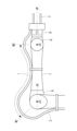
- FIG. 1 is a side view illustrating a robot system according to an embodiment of the present disclosure.
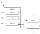
- FIG. 2 is a block diagram showing a configuration of a control device according to an embodiment of the present disclosure.
- 4 is a flowchart illustrating a control method according to an embodiment of the present disclosure.
- FIG. 11 is a schematic diagram for explaining an example of a control method according to an embodiment of the present disclosure.
- a control device 10 and a robot system 100 will be described below with reference to the drawings.
- a robot system 100 according to this embodiment includes a robot 1 and a control device 10 that controls the robot 1, as shown in FIG.
- the robot 1 is, for example, a six-axis articulated robot, and is a collaborative robot that works in collaboration with a worker.
- the robot 1 includes a base 3 placed on a horizontal floor surface F, and a rotating body 4 supported rotatably relative to the base 3 about a vertical first axis J1.
- the robot 1 also includes a plurality of arm members (movable members) and a wrist unit supported by the rotating body 4 and rotatably connected to each other.
- the robot 1 includes, as arm members, a first arm 5 supported rotatably relative to the rotating body 4 about a horizontal second axis J2, and a second arm 6 supported rotatably relative to the first arm 5 about a horizontal third axis J3.
- the wrist unit includes a first wrist element (movable member) 7 supported rotatably relative to the second arm 6 about a fourth axis J4 extending along a plane perpendicular to the third axis J3.
- the wrist unit includes a second wrist element (movable member) 8 supported rotatably relative to the first wrist element 7 about a fifth axis J5 perpendicular to the fourth axis J4.
- the wrist unit includes a third wrist element (movable member) 9 supported rotatably relative to the second wrist element 8 about a sixth axis J6 perpendicular to the fifth axis J5. That is, the robot 1 has six rotational joints A1 to A6 which rotate around the first axis J1 to the sixth axis J6, respectively.
- Each of the rotary joints A1 to A6 is driven by a motor (not shown) and a reducer that slows down the rotation of each motor.
- Each of the rotary joints A1 to A6 is also fitted with a six-axis force sensor (not shown) that detects the force acting on each joint shaft.
- a tool T is attached to the tip of the robot 1, i.e., the flange surface 9f provided on the third wrist element 9, by, for example, a user to whom the robot 1 is to be installed.
- the tool T is, for example, a hand equipped with a drive unit for gripping a workpiece or the like to be worked on.
- a line body 2 such as a cable for sending power and control signals to the tool T is also mounted on the robot 1 by a user or the like after the robot 1 is installed.
- the line body 2 is a bundle of these multiple cables using a conduit tube or the like.
- one end of the line body 2 is connected to the control device 10, and the other end is connected to the tool T.
- the filament 2 is attached to the outer surface of the robot 1, for example, with the robot 1 placed in the basic posture shown in Fig. 1.
- the basic posture of the robot 1 refers to, for example, a posture in which the third axis J3 is placed vertically above the second axis J2, the fifth axis J5 is placed parallel to and horizontally forward of the third axis J3, and the sixth axis J6 extends horizontally forward.
- the filament 2 extends from one end connected to the control device 10 located away from the robot 1 toward the base 3, and is raised upward at a position away from the base 3.
- the filament 2 then passes outside the rotational joints A1 and A2, is placed along the side of the first arm 5, and is fixed to the side of the first arm 5 by two fixing devices f1 and f2.
- the filament 2 is placed along the side of the first wrist element 7 and fixed to the side of the first wrist element 7 by the fixing device f3. Then, after passing outside the rotary joints A5 and A6, the other end of the filament 2 is connected to the tool T.
- the control device 10 includes an input device 11, at least one memory 12 such as a ROM or a RAM, and at least one processor 13 such as a CPU.
- the input device 11 is, for example, a combination of a display device such as a touch panel or a monitor with a keyboard, a mouse, push buttons, etc.
- the input device 11 accepts information about the tool T and the filament 2 input by a user or the like when setting conditions after the tool T and the filament 2 are attached to the robot 1.
- the memory 12 stores in advance the dimensions and center of gravity of each part of the robot 1 as initial settings.
- Examples of the dimensions of each part of the robot 1 include the distance L1 between the second axis J2 and third axis J3 of the first arm 5, and the distance L2 between the third axis J3 and fifth axis J5 of the second arm 6 and first wrist element 7.
- Another dimension is the distance L3 from the fifth axis J5 to the flange surface 9f.
- the center of gravity positions are the center position of dimension L1 on the longitudinal axis of the first arm 5, the center position of dimension L2 on the fourth axis J4, and the center position of dimension L3 on the sixth axis J6.
- the control device 10 has a function for setting the mass and center of gravity of attachment members and the like that are attached to the flange surface 9f.
- a user or the like uses this function to input the mass and center of gravity of a tool T that is attached to the flange surface 9f. This makes it possible to appropriately control the robot 1, taking into account the load acting on the robot 1 by the heavy object, even if a heavy object is attached to the flange surface 9f and the characteristics of the entire robot 1 change.
- control device 10 of the present disclosure has a function of setting the filament 2 connected to the tool T as a load. Specifically, the control device 10 stores in the memory 12 a setting program for setting the filament 2 as a load.
- a user or the like who has attached the filament 2 to the robot 1 starts a setting program stored in the memory 12, causing a predetermined user interface to be displayed on the screen of the input device 11.
- the user or the like then inputs, for example, the total weight (mass) of the filament 2 according to the displayed user interface.
- the processor 13 of the control device 10 divides the total weight into three weights based on the ratio L1:L2:L3 of the dimensions L1 to L3, which is stored as an initial setting value in the memory 12. The processor 13 then sets each of the three divided weights as a load acting on each center of gravity position, which is stored as an initial setting value in the memory 12.
- the weight ratio corresponding to dimension L1 is set as the load acting on the first arm 5 at the center of gravity of dimension L1.
- the weight ratio corresponding to dimension L2 is set as the load acting on the second arm 6 at the center of gravity of dimension L2.
- the weight ratio corresponding to dimension L3 is set as the load acting on the second wrist element 8 at the center of gravity of dimension L3.
- a total weight of the filament 2 is input to the input device 11 by a user or the like (step S1).
- the total weight of the filament 2 may be input together with the mass and center of gravity position of the tool T.
- the total weight of the filament 2 thus input is sent to the memory 12 together with the mass and center of gravity of the tool T and stored therein.
- the processor 13 reads out the dimensions L1 to L3 stored in the memory 12, and divides the input total weight of the filament 2 into three based on the ratio of the read out dimensions L1:L2:L3 (step S2).
- the processor 13 sets each of the three divided weights as the load acting on each movable member, i.e., the first arm 5, the second arm 6, and the second wrist element 8 (step S3).
- the total weight of the wire body 2 mounted on the robot 1 is distributed as a load corresponding to each movable member.
- control device 10 can detect contact between the robot 1 and an external object, etc., taking into account the load caused by the filament 2, for example.
- An example of a method for detecting contact when the control device 10 causes the robot 1 to perform a predetermined task will be described below.
- the processor 13 reads from the memory 12 and executes an operation program for making the robot 1 perform a specified task. As a result, the processor 13 rotates each of the motors of the rotary joints A1 to A6 of the robot 1 based on a plurality of operation commands contained in the operation program, and sequentially changes the posture of the robot 1.
- the processor 13 estimates the forces acting on the rotary joints A2, A3, and A5 based on the inertial forces acting on each movable member due to the movement and the weight (mass) of each movable member. The processor 13 then causes the robot 1 to perform the predetermined movement, acquires the detection values of the force sensors of the rotary joints A2, A3, and A5, and subtracts each estimated force from each acquired detection value.
- the processor 13 determines that a force greater than expected is acting on the robot 1, in other words, that the robot 1 is in contact with an external object or the like. If it determines that contact is occurring, it slows down or stops the movement of the robot 1. In this way, the control device 10 causes the robot 1 to perform a predetermined task while detecting contact with the robot 1.
- the processor 13 can take into account the effect of the load from the filament 2 attached to the robot 1 when estimating the forces acting on the rotational joints A2, A3, and A5. Therefore, the processor 13 can more accurately estimate the forces acting on the rotational joints A2, A3, and A5, and can prevent erroneous detection of contact of the robot 1.
- the load acting on the robot 1 by the filament 2 is calculated based on the dimensional ratio L1:L2:L3 pre-stored in the memory 12 and the total weight of the filament 2 input by the user, etc.
- the user, etc. does not need to input information regarding the length of the filament 2, and does not need to measure the length of the filament 2 corresponding to each movable member of the robot 1 when attaching the filament 2 to the robot 1, etc., thereby reducing the burden on the user, etc.
- the total weight of the filament 2 is set as the load acting on the robot 1, but instead, the weight of a portion of the filament 2 may be set as the load.
- the load can be set excluding the weight of the filament 2 between the end connected to the control device 10 and the contact point with the floor surface F, i.e., the weight of the part that does not actually act as a load on the robot 1. Therefore, the load setting for the robot 1 can be performed more accurately.
- the total weight of the filament 2 is divided according to the ratio of the dimensions L1, L2, and L3 corresponding to each movable member.
- the total weight of the filament 2 may be divided based on the values obtained by multiplying each of the dimensions L1, L2, and L3 by a coefficient greater than 1.
- the dimensions L1 and L2 corresponding to the excess length may be multiplied by a larger coefficient. This allows each of the dimensions L1, L2, and L3 to be weighted according to the extra length of the filament 2, making it possible to set a load with high accuracy that is more suited to the actual wiring configuration of the filament 2.
- the load from the filament 2 attached to the robot 1 is set to act on the center of gravity of each movable member of the robot 1.
- the position on which the load from the filament 2 acts may be set to any position input by the user, etc.
- the user may consider the wiring path of the filament 2 and set the center of gravity of the filament 2 in advance. In such a case, the user may input the center of gravity position that he or she has grasped in advance based on the wiring form of the filament 2 mounted on the robot 1 through the input device 11. This allows the load from the filament 2 to be set in accordance with the actual condition.
- the total weight of the filament 2 is distributed based on the dimensions L1 to L3 of each part of the robot 1.
- this may be input to estimate the load acting on each movable member based on the dimensions L1 to L3 stored in the memory 12.
- the user or the like inputs the mass per unit length of the filament 2 using the input device 11.
- the processor 13 multiplies each of the dimensions L1, L2, and L3 stored in the memory 12 by the input mass per unit length of the filament 2, and estimates each value obtained by multiplication as the load acting on each movable member.
- the magnitude of the load acting on each movable member may be estimated based on the measured length of each section.
- a user or the like actually measures the length of each section obtained by dividing the entire length of the filament 2 attached to the robot 1 according to the length of each movable member of the robot 1. Then, the user or the like inputs the actually measured length of each section into the input device 11 together with the mass per unit length of the filament 2.
- the processor 13 sets the load acting on each movable member to a value obtained by multiplying the input length of each section of the filament 2 by the input mass per unit length of the filament 2. This makes it possible to set the load acting on the robot 1 by the filament 2 more precisely.
- the midpoint in the longitudinal direction of the extra length may be measured as the section boundary of that section. That is, in the example shown in FIG. 4, since there is extra length on both sides of one section of the filament 2 corresponding to the second arm 6, it is sufficient to measure the length l along the filament 2 between midpoint M1 and midpoint M2 in the longitudinal direction of the extra length on both sides.
- the total weight of the filament 2 is input by the operator to the input device 11.
- the total weight of the filament 2 may be stored in advance in the memory 12 as an initial setting value.
- the rotary joints A2, A3, and A5 that drive the first arm 5, the second arm 6, and the second wrist element 8 are exemplified as rotary joints on which the mass of the filament 2 acts as a large load.
- the position of the center of gravity of the filament 2 can be set with high precision, it may be possible to set the load acting on the rotary joints A1, A4, and A6.
- control device 10 is described as controlling an articulated robot having six rotational joints A1 to A6, but the control target of the control device 10 is not limited to this.
- control device 10 may be applied to the control of a linear motion robot having at least one linear motion mechanism.
- control method according to this embodiment has been applied to contact detection of the robot 1, which is a collaborative robot
- the present invention is not limited to this and may be applied, for example, to the operation control of a robot 1 other than a collaborative robot.
- the load from the umbilical member 2 attached to the robot 1 significantly affects the dynamic characteristics of the robot 1. Therefore, by applying the control method according to this embodiment, it is possible to obtain the advantage that the robot 1 operating at high speed can be controlled more accurately.
- Appendix 1 A control device for controlling a robot having a plurality of movable members, A robot control device comprising at least one processor, the processor acquiring a mass of a filament that is retrofitted to the robot, and setting the acquired mass of the filament as a load acting on each of the movable members.
- Appendix 2 A control device as described in Appendix 1, comprising a memory for storing the length of each of the movable members, wherein the processor distributes the acquired mass of the filament as a load acting on each of the movable members in a proportion corresponding to the length of each of the movable members stored in the memory.
- Appendix 3 a memory for storing a length of each of the movable members, the processor A control device as described in Appendix 1, which calculates the load acting on each of the movable members by acquiring the mass per unit length of the filament and multiplying the acquired mass per unit length of the filament by a length corresponding to the length of each of the movable members stored in the memory.
- Appendix 4 A control device as described in Appendix 3, wherein the length corresponding to the length of each of the movable members stored in the memory is calculated by multiplying the length of each of the movable members stored in the memory by a coefficient greater than 1. (Appendix 5) 5.
- the control device detects interference between the robot and an object or person in the vicinity of the robot based on values including the mass of each of the movable members and a load acting on each of the movable members.
- Appendix 6 A robot system comprising the robot and the control device according to any one of Supplementary Note 1 to Supplementary Note 5.
- Appendix 7) A control method for controlling a robot having a plurality of movable members, the control method comprising: acquiring a mass of a filament that is retrofitted to the robot; and setting the acquired mass of the filament as a load acting on each of the movable members.
Landscapes
- Engineering & Computer Science (AREA)
- Robotics (AREA)
- Mechanical Engineering (AREA)
- Human Computer Interaction (AREA)
- Manipulator (AREA)
- Numerical Control (AREA)
Abstract
L'invention concerne un dispositif de commande (10) pour commander un robot (1) comprenant une pluralité d'éléments mobiles, le dispositif de commande (10) comportant au moins un processeur, le processeur faisant l'acquisition de la masse d'un corps de fil (2) installé rétroactivement sur le robot (1), et réglant la masse acquise du corps de fil (2) en tant que charge agissant sur chacun des éléments mobiles (5), (6), (8).
Priority Applications (4)
| Application Number | Priority Date | Filing Date | Title |
|---|---|---|---|
| CN202380100999.4A CN121605021A (zh) | 2023-08-22 | 2023-08-22 | 机器人的控制装置、控制方法以及机器人系统 |
| PCT/JP2023/030098 WO2025041250A1 (fr) | 2023-08-22 | 2023-08-22 | Dispositif de commande de robot, procédé de commande et système de robot |
| DE112023006408.3T DE112023006408T5 (de) | 2023-08-22 | 2023-08-22 | Robotersteuervorrichtung, steuerverfahren und robotersystem |
| TW113129256A TW202528103A (zh) | 2023-08-22 | 2024-08-05 | 機器人的控制裝置、控制方法及機器人系統 |
Applications Claiming Priority (1)
| Application Number | Priority Date | Filing Date | Title |
|---|---|---|---|
| PCT/JP2023/030098 WO2025041250A1 (fr) | 2023-08-22 | 2023-08-22 | Dispositif de commande de robot, procédé de commande et système de robot |
Publications (1)
| Publication Number | Publication Date |
|---|---|
| WO2025041250A1 true WO2025041250A1 (fr) | 2025-02-27 |
Family
ID=94731841
Family Applications (1)
| Application Number | Title | Priority Date | Filing Date |
|---|---|---|---|
| PCT/JP2023/030098 Pending WO2025041250A1 (fr) | 2023-08-22 | 2023-08-22 | Dispositif de commande de robot, procédé de commande et système de robot |
Country Status (4)
| Country | Link |
|---|---|
| CN (1) | CN121605021A (fr) |
| DE (1) | DE112023006408T5 (fr) |
| TW (1) | TW202528103A (fr) |
| WO (1) | WO2025041250A1 (fr) |
Citations (3)
| Publication number | Priority date | Publication date | Assignee | Title |
|---|---|---|---|---|
| JP2012218104A (ja) * | 2011-04-08 | 2012-11-12 | Toyota Motor Corp | トルク算出装置、トルク算出方法、及びプログラム |
| JP2016203304A (ja) * | 2015-04-22 | 2016-12-08 | キヤノン株式会社 | ロボット装置、およびロボット装置の制御方法 |
| WO2022138368A1 (fr) * | 2020-12-22 | 2022-06-30 | ファナック株式会社 | Dispositif robotisé |
Family Cites Families (1)
| Publication number | Priority date | Publication date | Assignee | Title |
|---|---|---|---|---|
| JP5941083B2 (ja) | 2014-03-12 | 2016-06-29 | ファナック株式会社 | 外部環境との接触を検知するロボット制御装置 |
-
2023
- 2023-08-22 WO PCT/JP2023/030098 patent/WO2025041250A1/fr active Pending
- 2023-08-22 DE DE112023006408.3T patent/DE112023006408T5/de active Pending
- 2023-08-22 CN CN202380100999.4A patent/CN121605021A/zh active Pending
-
2024
- 2024-08-05 TW TW113129256A patent/TW202528103A/zh unknown
Patent Citations (3)
| Publication number | Priority date | Publication date | Assignee | Title |
|---|---|---|---|---|
| JP2012218104A (ja) * | 2011-04-08 | 2012-11-12 | Toyota Motor Corp | トルク算出装置、トルク算出方法、及びプログラム |
| JP2016203304A (ja) * | 2015-04-22 | 2016-12-08 | キヤノン株式会社 | ロボット装置、およびロボット装置の制御方法 |
| WO2022138368A1 (fr) * | 2020-12-22 | 2022-06-30 | ファナック株式会社 | Dispositif robotisé |
Also Published As
| Publication number | Publication date |
|---|---|
| TW202528103A (zh) | 2025-07-16 |
| DE112023006408T5 (de) | 2026-04-02 |
| CN121605021A (zh) | 2026-03-03 |
Similar Documents
| Publication | Publication Date | Title |
|---|---|---|
| JP5821210B2 (ja) | 水平多関節ロボット及び水平多関節ロボットの制御方法 | |
| CN102649270B (zh) | 机器人系统、机器人控制装置以及机器人控制方法 | |
| TWI621004B (zh) | Robot system monitoring device | |
| JP6008121B2 (ja) | ロボットおよびロボット制御装置 | |
| CN111376267B (zh) | 工业用机器人系统 | |
| CN103213134B (zh) | 机械手的控制方法和机械手 | |
| KR102007536B1 (ko) | 토크를 검출하기 위한 방법 및 산업용 로봇 | |
| JP6584102B2 (ja) | ロボット装置、ロボット制御方法、プログラム、記録媒体、及び物品の製造方法 | |
| JP6705851B2 (ja) | 振動解析装置および振動解析方法 | |
| JP6575200B2 (ja) | ロボット、制御装置およびロボットシステム | |
| JP7267688B2 (ja) | ロボットシステム、ロボットアームの制御方法、物品の製造方法、駆動装置および駆動装置の制御方法 | |
| JP2012171052A5 (fr) | ||
| JP6816495B2 (ja) | ロボットのたわみ補正方法、ロボットの制御装置 | |
| JP7015276B2 (ja) | 産業用ロボットシステム | |
| JP2019098407A (ja) | ロボット | |
| KR20110004788A (ko) | 머니퓰레이터를 작동시키기 위한 방법 및 장치 | |
| JP2020151812A (ja) | ロボットを用いて負荷の重量及び重心位置を推定するための装置、方法及びプログラム | |
| KR20110048870A (ko) | 4축 팔레타이징 로봇용 부하 추정 방법 | |
| CN110871456A (zh) | 机器人 | |
| JP5316396B2 (ja) | ロボットのばね定数同定方法およびロボットのばね定数同定装置 | |
| JP7404627B2 (ja) | ロボットシステム、制御装置、および制御方法 | |
| JP2019042906A (ja) | ロボットの外部接触2重チェック装置 | |
| WO2025041250A1 (fr) | Dispositif de commande de robot, procédé de commande et système de robot | |
| JP4944661B2 (ja) | ロボット出力の測定方法 | |
| JP5316395B2 (ja) | ロボットのばね定数同定方法およびロボットのばね定数同定装置 |
Legal Events
| Date | Code | Title | Description |
|---|---|---|---|
| 121 | Ep: the epo has been informed by wipo that ep was designated in this application |
Ref document number: 23949711 Country of ref document: EP Kind code of ref document: A1 |
|
| ENP | Entry into the national phase |
Ref document number: 2025541204 Country of ref document: JP Kind code of ref document: A |
|
| WWE | Wipo information: entry into national phase |
Ref document number: 2025541204 Country of ref document: JP Ref document number: 112023006408 Country of ref document: DE |