WO2025041247A1 - 電力制御システム - Google Patents
電力制御システム Download PDFInfo
- Publication number
- WO2025041247A1 WO2025041247A1 PCT/JP2023/030089 JP2023030089W WO2025041247A1 WO 2025041247 A1 WO2025041247 A1 WO 2025041247A1 JP 2023030089 W JP2023030089 W JP 2023030089W WO 2025041247 A1 WO2025041247 A1 WO 2025041247A1
- Authority
- WO
- WIPO (PCT)
- Prior art keywords
- power
- discharge
- control
- power supply
- voltage
- Prior art date
- Legal status (The legal status is an assumption and is not a legal conclusion. Google has not performed a legal analysis and makes no representation as to the accuracy of the status listed.)
- Pending
Links
Images


Classifications
-
- H—ELECTRICITY
- H02—GENERATION; CONVERSION OR DISTRIBUTION OF ELECTRIC POWER
- H02J—ELECTRIC POWER NETWORKS; CIRCUIT ARRANGEMENTS OR SYSTEMS FOR SUPPLYING OR DISTRIBUTING ELECTRIC POWER; SYSTEMS FOR STORING ELECTRIC ENERGY
- H02J1/00—Circuit arrangements for DC mains or DC distribution networks
-
- H—ELECTRICITY
- H02—GENERATION; CONVERSION OR DISTRIBUTION OF ELECTRIC POWER
- H02J—ELECTRIC POWER NETWORKS; CIRCUIT ARRANGEMENTS OR SYSTEMS FOR SUPPLYING OR DISTRIBUTING ELECTRIC POWER; SYSTEMS FOR STORING ELECTRIC ENERGY
- H02J1/00—Circuit arrangements for DC mains or DC distribution networks
- H02J1/10—Parallel operation of DC sources
- H02J1/12—Parallel operation of DC sources having power converters with further DC sources without power converters
-
- H—ELECTRICITY
- H02—GENERATION; CONVERSION OR DISTRIBUTION OF ELECTRIC POWER
- H02J—ELECTRIC POWER NETWORKS; CIRCUIT ARRANGEMENTS OR SYSTEMS FOR SUPPLYING OR DISTRIBUTING ELECTRIC POWER; SYSTEMS FOR STORING ELECTRIC ENERGY
- H02J7/00—Circuit arrangements for charging or discharging batteries or for supplying loads from batteries
- H02J7/34—Parallel operation in networks using both storage and other DC sources, e.g. providing buffering
Definitions
- the multiple proportional charge/discharge controllers are connected to multiple power supply sources, respectively.
- the multiple power supply sources are a solar power generation device, a storage battery, and a commercial power source.
- the commercial power source is connected to the DC power supply line via a rectifier. Note that in this power control system, the rectifier is voltage controlled to control the charging and discharging of the storage battery, and the output voltage of the solar power generation is controlled to be the maximum output voltage.
- the present invention aims to provide a power control system that can solve the above-mentioned problems.
- the power control system disclosed in this specification is connected to a power supply DC line to which a load and a plurality of proportional charge/discharge controllers, each of which is connected to a plurality of power supply sources including a renewable energy power generation device, a power storage device, and a commercial power source, are connected.
- the power control system includes a capacitor electrically connected to the power supply DC line so that the potential difference with the load due to DC conversion does not fluctuate, and a control unit that controls the plurality of proportional charge/discharge controllers.
- the control unit performs a voltage control process for performing DC voltage feedback control for one specific controller of the plurality of proportional charge/discharge controllers to bring the voltage of the power supply DC line closer to a target voltage, and a switching process for switching the specific controller from one of the proportional charge/discharge controllers to another of the proportional charge/discharge controllers.
- the capacitor is connected to the power supply DC line so that the potential difference with the load due to DC conversion does not fluctuate, so the time change (response, amplitude) of the voltage of the power supply DC line becomes small according to the capacitance of the capacitor.
- the voltage of the power supply DC line fluctuates gently in response to a sudden fluctuation in the load voltage. Therefore, even if a configuration is adopted in which DC voltage feedback control is performed only on a specific controller, the effect of fluctuations in the voltage of the power supply DC line on the control of other proportional charge/discharge controllers can be suppressed.
- the specific controller that is the target of the DC voltage feedback control is switched from one proportional charge/discharge controller to another proportional charge/discharge controller. Therefore, according to this power control system, power can be supplied to the load in a variety of power supply patterns compared to a configuration in which the specific controller is fixed to one proportional charge/discharge controller.
- the multiple power supply sources may include multiple storage devices, and the control unit may be configured to include the proportional charge/discharge controller connected to each of the multiple storage devices as a switching target of the specific controller in the switching process.
- a storage device (hereinafter referred to as a "target storage device") connected to a proportional charge/discharge controller that is a switching target of the specific controller (DC voltage feedback control) cannot be charged or discharged by current control during that time.
- a problem occurs in which the opportunity to charge or discharge only that one storage device by current control is restricted.
- multiple storage devices are configured as target storage devices, so that it is possible to suppress the occurrence of a problem in which the opportunity to charge or discharge only a specific storage device by current control is restricted among the multiple storage devices.
- the power control system 100 has a configuration for suppressing mutual interference of the DC voltage feedback control of the proportional charge/discharge controllers.
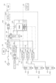
- the proportional charge/discharge controllers are the AC/DC converter 22 connected to the commercial power source 20, the DC/DC converter 14B connected to the solar panel 12, and the DC/DC converter 130 connected to the LIB module 50 (see FIG. 1). These multiple proportional charge/discharge controllers (22, 14B, 130) are controlled by the control unit 121.
- the configuration of the power control system 100 and the like in the above embodiment is merely an example, and various modifications are possible.
- the solar power generation device 10, the commercial power source 20, and the LIB module 50 are exemplified as the power supply source, but the power supply source may be a renewable energy power generation device that generates power using renewable energy other than solar energy (e.g., natural energy such as wind power, hydroelectric power, geothermal power, and thermal power).
- the power supply source may be a power generation device that does not use renewable energy, such as a gas generator, or a power supply source other than the commercial power source 20 and the LIB module 50.
- the power control system 100 may be configured to incorporate at least one of the AC/DC converter 22, the DC/DC converter 14B, and the DC/DC converter 130. Furthermore, multiple power control systems 100 may be used connected in series or in parallel. Furthermore, the multiple devices constituting the power control system 100 (LIC module 110, DC/DC converter 130, etc.) are connected to a common power supply DC line LW, and therefore these multiple devices are connected in parallel with each other. However, when multiple power control systems 100 are connected, some devices may be connected in series.
- the AC/DC converter 22, the DC/DC converter 14B, and the DC/DC converter 130 are exemplified as proportional charge/discharge controllers, but any proportional charge/discharge controller in which the input and output are proportional may be used, for example, a proportional charge/discharge controller configured by combining an AC/DC converter and a DC/DC converter.
- proportional charge/discharge controllers are not limited to controllers that control both charging and discharging, but also include controllers that control only one of charging and discharging.
- the LIB module 50 may be configured with multiple LIBs 52 connected in parallel, or multiple LIBs 52 connected in series and parallel, or may be configured with only one LIB 52.
- the LIB module 50 (LIB 52) is exemplified as the power storage device, but other types of power storage devices such as lead-acid batteries may also be used.
- the number of LIB modules 50 connected to the power control system 100 may be one, two, or four or more.
- the potential of the one end of the LIC module 110 and the potential of the side connected to the power supply DC line LW in the load 30 are substantially the same, but the potential of the one end of the LIC module 110 and the potential of the side connected to the power supply DC line LW in the load 30 may be different, and the difference between the two potentials may not fluctuate.
- the LIC module 110 has a higher correlation between voltage and capacity than the LIB module 50, so that the charging and discharging of the LIC module 110 can be indirectly controlled by controlling the charging and discharging of the LIB module 50 without having to provide a dedicated DC/DC converter.
- any one of the processes of S130 (grid voltage control mode), S140 (grid power control mode), and S150 (independent operation control mode) may not be executed.
- the SOC is used as an example of the evaluation of the storage state, but it is not limited to this, and C rate, depth of discharge, and degree of deterioration may also be used.
- the evaluation of the storage state may also be a comprehensive evaluation of at least two of the SOC, C rate, depth of discharge, and degree of deterioration (e.g., SOH, number of charges, charge time, number of discharges, discharge time, number of charges and discharges, and charge and discharge time).
- the evaluation of the storage state may also be the temperature of the storage device.
- the DC/DC converter 130 of the LIB module 50 with a medium SOC may simply be the target of the specific controller.
- the non-target DC/DC converter 130 of the LIB module 50 with the highest or lowest SOC may not be the target of the specific controller.
- Photovoltaic power generation device 12 Solar panel 14: PV converter 14A: Power generation equipment sensor 14B: DC/DC converter 20: Commercial power supply 22: AC/DC converter 30: Load 40: Master controller 50: LIB module 52: LIB 100: Power control system 110: LIC module 112: LIC 120: PCU 121: Control unit 122: Memory unit 123: Interface unit 130: DC/DC converter 132: Connection unit 140: Capacitor sensor 150: Load sensor 160: DC/AC converter LW: Power supply DC line
Landscapes
- Engineering & Computer Science (AREA)
- Power Engineering (AREA)
- Charge And Discharge Circuits For Batteries Or The Like (AREA)
Abstract
Description
A-1.電力制御システム100と外部装置との電気的構成:
図1は、本実施形態における電力制御システム100と外部装置との電気的構成を示す説明図である。図1には、外部装置として、太陽光発電装置10と、商用電源(系統)20と、負荷30と、マスターコントローラ40と、複数のLIBモジュール50と、が示されており、これらの外部装置と電力制御システム100とが電力供給直流ラインLWを介して電気的に接続されている。負荷30の例としては、製造業で用いられ、比較的高速に加速動作と減速動作とを行う機器(工作機器、産業用ロボット、搬送機器、繊維、食品加工機器など)や、比較的出力が大きく、停電時での動作を必要とする機器(エレベータ、空調機器やコンプレッサなど)が挙げられる。なお、図1では、3つのLIBモジュール50(50A,50B,50C)が例示されている。LIBモジュール50は、蓄電装置の一例である。
電力制御システム100は、比例式充放電制御器の直流電圧フィードバック制御の相互干渉を抑制するための構成を有している。上述したように、本実施形態では、比例式充放電制御器は、商用電源20に接続されているAC/DCコンバータ22と、ソーラーパネル12に接続されているDC/DCコンバータ14Bと、LIBモジュール50に接続されているDC/DCコンバータ130とである(図1参照)。これらの複数の比例式充放電制御器(22,14B、130)は、制御部121によって制御される。
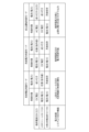
図2は、PCU120の制御部121が実行する電力制御処理を示すフローチャートであり、図3は、各電力供給モードにおける各比例式充放電制御器の制御内容を示す説明図である。本電力制御処理は、特定制御器だけに対して直流電圧フィードバック制御を行いつつ、その特定制御器を、一の比例式充放電制御器から別の一の比例式充放電制御器に切り替える処理である。
商用電源20が電力供給直流ラインLWに接続されている系統連携時には、制御部121は、自立運転条件が満たされないと判断し(S110:NO)、次に、系統電力制御条件が満たされるか否かを判断する(S120)。系統電力制御条件は、商用電源20のAC/DCコンバータ22に対して、電力フィードバック制御を行うための条件である。
商用電源20が電力供給直流ラインLWから切り離された非系統連携時には、制御部121は、自立運転条件が満たされると判断した場合(S110:YES)、自立運転制御モードを実行する(S150)。自立運転制御モードは、太陽光発電装置10のPV電力Wpと、LIBモジュール50のストレージ電力Wsとを利用して、負荷30への電力供給を行うとともに、PV電力Wpの余剰電力(=Wp-Wr)を利用してLIBモジュール50への充電を行うモードである。このとき、AC/DCコンバータ22のAC電流は、負荷30への供給電力に応じて成り行きとなる。
図4は、PCU120の制御部121が実行するSOC調整処理を示すフローチャートである。SOC調整処理は、電力制御システム100に接続された複数のLIBモジュール50間のSOC(State of Charge、充電率)のバラツキを抑制する(均一化する)ための処理である。制御部121は、上記電力制御処理と並行して、本SOC調整処理を所定時間ごとに繰り返し実行する。
制御部121は、複数のLIBモジュール50のDC/DCコンバータ130のいずれかが特定制御器の対象であると判断した場合(S220:YES)、複数のDC/DCコンバータ130の中から、1つのDC/DCコンバータ130を特定制御器の切替対象(直流電圧フィードバック制御の対象)として選択する(S230)。S230の処理は、選択処理の一例である。本実施形態では、推定されたSOCが基準SOCに最も近いLIBモジュール50のDC/DCコンバータ130を選択する。基準SOCは、例えば次の通りである。SOCは、蓄電状態の評価の一例である。
複数のLIBモジュール50のそれぞれのSOCの平均値
複数のLIBモジュール50のそれぞれのSOCのうち、最高値と最低値との間の中心値
(3)予め定められた固定値(例えば50%)
(1)「SOC>基準SOC」であるLIBモジュール50の対象外DC/DCコンバータ130:放電を行う
(2)「SOC<基準SOC」であるLIBモジュール50の対象外DC/DCコンバータ130:充電を行う
さらに、次の(3)を加えてもよい。
(3)基準SOCとの差が基準範囲内(例えば基準SOCに対して±5%以内)であるLIBモジュール50の対象外DC/DCコンバータ130:充電も放電も行わない
各DC/DCコンバータ130に対する制御内容が決定されると、制御部121は、決定に応じた制御を実施し(S260)、本SOC調整処理を終了する。
制御部121は、LIBモジュール50のDC/DCコンバータ130が特定制御器の対象ではないと判断した場合(S220:NO)、対象外DC/DCコンバータ130を、電流フィードバック制御または電力フィードバック制御の対象とする。この場合、全てのDC/DCコンバータ130が対象外DC/DCコンバータ130である。制御部121は、対象外DC/DCコンバータ130のそれぞれについて、SOCに基づき、充電を行うか、放電を行うか、充放電しないかを決定する(S250)。例えば、次のように決定してもよい。
(1)基準SOCとの差が基準範囲内(例えば基準SOCに対して±5%以内)であるLIBモジュール50の対象外DC/DCコンバータ130:充電も放電も行わない
(2)「基準SOCとの差が基準範囲外、かつ、SOC>基準SOC」であるLIBモジュール50の対象外DC/DCコンバータ130:放電を行う
(3)「基準SOCとの差が基準範囲外、かつ、SOC<基準SOC」であるLIBモジュール50の対象外DC/DCコンバータ130:充電を行う
各DC/DCコンバータ130に対する制御内容が決定されると、制御部121は、決定に応じた制御を実施し(S260)、本SOC調整処理を終了する。
本実施形態に係る電力制御システムでは、電力供給直流ラインLWに対して、LICモジュール110が負荷30との直流換算による電位差が変動しないように接続されているため、電力供給直流ラインLWの電圧の時間的変化(応答、振幅)がLICモジュール110の容量に応じて小さくなる。例えば、負荷電圧の急激な変動に対して電力供給直流ラインLWの電圧が緩やかに変動する。このため、特定制御器だけに対して直流電圧フィードバック制御を行う構成を採用しても、電力供給直流ラインLWの電圧の変動が他の比例式充放電制御器に対する制御に与える影響を抑制することができる。しかも、直流電圧フィードバック制御の対象である特定制御器が、一の比例式充放電制御器(例えばAC/DCコンバータ22)から別の一の比例式充放電制御器(例えばDC/DCコンバータ130)に切り替えられる。このため、本実施形態によれば、特定制御器が一の比例式充放電制御器に固定された構成に比べて、多様な電力供給パターンで負荷への電力供給を行うことができる。
本発明は、上述の実施形態に限られるものではなく、その要旨を逸脱しない範囲において種々の形態に変形することができ、例えば次のような変形も可能である。
Claims (5)
- 再生可能エネルギー利用発電装置と蓄電装置と商用電源とを含む複数の電力供給源のそれぞれに接続される複数の比例式充放電制御器と負荷とが接続される電力供給直流ラインに接続される電力制御システムであって、
前記電力供給直流ラインに対して、前記負荷との直流換算による電位差が変動しないように電気的に接続されるキャパシタと、
前記複数の比例式充放電制御器を制御する制御部と、を備え、
前記制御部は、
前記複数の比例式充放電制御器のうちの1つの特定制御器に対して、前記電力供給直流ラインの電圧を目標電圧に近づける直流電圧フィードバック制御を行う電圧制御処理と、
前記特定制御器を、一の前記比例式充放電制御器から別の一の前記比例式充放電制御器に切り替える切替処理と、を行う、電力制御システム。 - 請求項1に記載の電力制御システムであって、
前記複数の電力供給源は、複数の前記蓄電装置を含み、
前記制御部は、前記切替処理において、前記特定制御器の切替対象に、前記複数の蓄電装置のそれぞれに接続される前記比例式充放電制御器を含む、電力制御システム。 - 請求項2に記載の電力制御システムであって、
前記制御部は、
前記複数の蓄電装置のうち、SOCとCレートと放電深度と劣化度合いとの少なくとも1つに基づく蓄電状態の評価の高低に基づき、一の前記蓄電装置を選択する選択処理を実行し、
前記切替処理では、前記特定制御器を、前記複数の蓄電装置のうち、前記選択処理にて選択された前記蓄電装置に接続された前記比例式充放電制御器に優先的に切り替える、電力制御システム。 - 請求項3に記載の電力制御システムであって、
前記複数の電力供給源は、3つ以上の前記蓄電装置を含み、
前記蓄電状態の評価は、前記蓄電装置のSOCであり、
前記制御部は、
前記選択処理において、前記複数の蓄電装置のうち、前記SOCが中位である前記蓄電装置を選択する、電力制御システム。 - 請求項2に記載の電力制御システムであって、
前記制御部は、
複数の蓄電装置に接続される前記比例式充放電制御器が前記特定制御器とされていない場合、前記複数の前記蓄電装置について、SOCとCレートと放電深度と劣化度合いとの少なくとも1つに基づく蓄電状態の評価のバラツキが抑制されるように前記複数の前記蓄電装置の少なくとも1つに対して直流電流フィードバック制御を行う電流制御処理を行う、電力制御システム。
Priority Applications (1)
| Application Number | Priority Date | Filing Date | Title |
|---|---|---|---|
| PCT/JP2023/030089 WO2025041247A1 (ja) | 2023-08-22 | 2023-08-22 | 電力制御システム |
Applications Claiming Priority (1)
| Application Number | Priority Date | Filing Date | Title |
|---|---|---|---|
| PCT/JP2023/030089 WO2025041247A1 (ja) | 2023-08-22 | 2023-08-22 | 電力制御システム |
Publications (1)
| Publication Number | Publication Date |
|---|---|
| WO2025041247A1 true WO2025041247A1 (ja) | 2025-02-27 |
Family
ID=94731836
Family Applications (1)
| Application Number | Title | Priority Date | Filing Date |
|---|---|---|---|
| PCT/JP2023/030089 Pending WO2025041247A1 (ja) | 2023-08-22 | 2023-08-22 | 電力制御システム |
Country Status (1)
| Country | Link |
|---|---|
| WO (1) | WO2025041247A1 (ja) |
Citations (5)
| Publication number | Priority date | Publication date | Assignee | Title |
|---|---|---|---|---|
| WO2012144357A1 (ja) * | 2011-04-18 | 2012-10-26 | シャープ株式会社 | 電力供給装置、電力供給装置の制御方法、および直流給電システム |
| JP2015204652A (ja) * | 2014-04-11 | 2015-11-16 | 株式会社明電舎 | 電力変換システム |
| JP2019030110A (ja) * | 2017-07-28 | 2019-02-21 | 住友電気工業株式会社 | 蓄電池システム及びその放電制御方法 |
| WO2021192107A1 (ja) * | 2020-03-25 | 2021-09-30 | Tdk株式会社 | 給電システム、及び電力管理装置 |
| WO2022249377A1 (ja) * | 2021-05-27 | 2022-12-01 | 武蔵精密工業株式会社 | 電力制御システム |
-
2023
- 2023-08-22 WO PCT/JP2023/030089 patent/WO2025041247A1/ja active Pending
Patent Citations (5)
| Publication number | Priority date | Publication date | Assignee | Title |
|---|---|---|---|---|
| WO2012144357A1 (ja) * | 2011-04-18 | 2012-10-26 | シャープ株式会社 | 電力供給装置、電力供給装置の制御方法、および直流給電システム |
| JP2015204652A (ja) * | 2014-04-11 | 2015-11-16 | 株式会社明電舎 | 電力変換システム |
| JP2019030110A (ja) * | 2017-07-28 | 2019-02-21 | 住友電気工業株式会社 | 蓄電池システム及びその放電制御方法 |
| WO2021192107A1 (ja) * | 2020-03-25 | 2021-09-30 | Tdk株式会社 | 給電システム、及び電力管理装置 |
| WO2022249377A1 (ja) * | 2021-05-27 | 2022-12-01 | 武蔵精密工業株式会社 | 電力制御システム |
Similar Documents
| Publication | Publication Date | Title |
|---|---|---|
| TWI774142B (zh) | 交流負荷供電系統和方法 | |
| CN111628558B (zh) | 混合储能系统的能量管理和容量配置的优化系统及方法 | |
| CN112510737B (zh) | 一种光伏储能充电站并离网协同控制方法及系统 | |
| JP6430775B2 (ja) | 蓄電池装置 | |
| CN104092278A (zh) | 应用于光伏储能系统的能量管理方法 | |
| CN112510756A (zh) | 一种基于功率水平的微电网光储充协调运行方法及系统 | |
| CN106786490A (zh) | 分布式直流微电网能量控制方法 | |
| CN105262127A (zh) | 一种光伏发电混合储能系统的功率自适应控制方法 | |
| WO2011122681A1 (ja) | 系統安定化システム、電力供給システム、集中管理装置の制御方法および集中管理装置のプログラム | |
| WO2021192107A1 (ja) | 給電システム、及び電力管理装置 | |
| WO2022110824A1 (zh) | 能量调度方法、装置及系统 | |
| WO2022172457A1 (ja) | 電力管理装置、及び給電システム | |
| EP3567691B1 (en) | Composite power storage system and power storage method | |
| CN115513932A (zh) | 一种风光储微电网管控方法、系统、终端设备及存储介质 | |
| JP6614010B2 (ja) | 蓄電池システム | |
| EP4027476B1 (en) | Energy storage system comprising multiple battery packs | |
| JP6768571B2 (ja) | 電力制御装置、方法及び発電システム | |
| WO2022004615A1 (ja) | 電力変換器、電力変換器の制御方法、電力システム、電力システムの制御方法及びプログラム | |
| EP4675877A1 (en) | Energy storage power generation system and control method thereof | |
| WO2025041247A1 (ja) | 電力制御システム | |
| WO2022249377A1 (ja) | 電力制御システム | |
| WO2024131045A1 (zh) | 光伏设备以及提升光伏设备的光伏利用率的方法 | |
| JP2024017513A (ja) | 分散型電源システム及び分散型電源の制御方法 | |
| JP7806214B2 (ja) | 電力制御システム | |
| KR20220000865A (ko) | 하이브리드 충방전 시스템 |
Legal Events
| Date | Code | Title | Description |
|---|---|---|---|
| 121 | Ep: the epo has been informed by wipo that ep was designated in this application |
Ref document number: 23949708 Country of ref document: EP Kind code of ref document: A1 |
|
| ENP | Entry into the national phase |
Ref document number: 2025541201 Country of ref document: JP Kind code of ref document: A |
|
| WWE | Wipo information: entry into national phase |
Ref document number: 2025541201 Country of ref document: JP |
|
| WWE | Wipo information: entry into national phase |
Ref document number: 202617019004 Country of ref document: IN |
|
| NENP | Non-entry into the national phase |
Ref country code: DE |