WO2025041247A1 - Electric power control system - Google Patents
Electric power control system Download PDFInfo
- Publication number
- WO2025041247A1 WO2025041247A1 PCT/JP2023/030089 JP2023030089W WO2025041247A1 WO 2025041247 A1 WO2025041247 A1 WO 2025041247A1 JP 2023030089 W JP2023030089 W JP 2023030089W WO 2025041247 A1 WO2025041247 A1 WO 2025041247A1
- Authority
- WO
- WIPO (PCT)
- Prior art keywords
- power
- discharge
- control
- power supply
- voltage
- Prior art date
- Legal status (The legal status is an assumption and is not a legal conclusion. Google has not performed a legal analysis and makes no representation as to the accuracy of the status listed.)
- Pending
Links
Images


Classifications
-
- H—ELECTRICITY
- H02—GENERATION; CONVERSION OR DISTRIBUTION OF ELECTRIC POWER
- H02J—ELECTRIC POWER NETWORKS; CIRCUIT ARRANGEMENTS OR SYSTEMS FOR SUPPLYING OR DISTRIBUTING ELECTRIC POWER; SYSTEMS FOR STORING ELECTRIC ENERGY
- H02J1/00—Circuit arrangements for DC mains or DC distribution networks
-
- H—ELECTRICITY
- H02—GENERATION; CONVERSION OR DISTRIBUTION OF ELECTRIC POWER
- H02J—ELECTRIC POWER NETWORKS; CIRCUIT ARRANGEMENTS OR SYSTEMS FOR SUPPLYING OR DISTRIBUTING ELECTRIC POWER; SYSTEMS FOR STORING ELECTRIC ENERGY
- H02J1/00—Circuit arrangements for DC mains or DC distribution networks
- H02J1/10—Parallel operation of DC sources
- H02J1/12—Parallel operation of DC sources having power converters with further DC sources without power converters
-
- H—ELECTRICITY
- H02—GENERATION; CONVERSION OR DISTRIBUTION OF ELECTRIC POWER
- H02J—ELECTRIC POWER NETWORKS; CIRCUIT ARRANGEMENTS OR SYSTEMS FOR SUPPLYING OR DISTRIBUTING ELECTRIC POWER; SYSTEMS FOR STORING ELECTRIC ENERGY
- H02J7/00—Circuit arrangements for charging or discharging batteries or for supplying loads from batteries
- H02J7/34—Parallel operation in networks using both storage and other DC sources, e.g. providing buffering
Definitions
- the multiple proportional charge/discharge controllers are connected to multiple power supply sources, respectively.
- the multiple power supply sources are a solar power generation device, a storage battery, and a commercial power source.
- the commercial power source is connected to the DC power supply line via a rectifier. Note that in this power control system, the rectifier is voltage controlled to control the charging and discharging of the storage battery, and the output voltage of the solar power generation is controlled to be the maximum output voltage.
- the present invention aims to provide a power control system that can solve the above-mentioned problems.
- the power control system disclosed in this specification is connected to a power supply DC line to which a load and a plurality of proportional charge/discharge controllers, each of which is connected to a plurality of power supply sources including a renewable energy power generation device, a power storage device, and a commercial power source, are connected.
- the power control system includes a capacitor electrically connected to the power supply DC line so that the potential difference with the load due to DC conversion does not fluctuate, and a control unit that controls the plurality of proportional charge/discharge controllers.
- the control unit performs a voltage control process for performing DC voltage feedback control for one specific controller of the plurality of proportional charge/discharge controllers to bring the voltage of the power supply DC line closer to a target voltage, and a switching process for switching the specific controller from one of the proportional charge/discharge controllers to another of the proportional charge/discharge controllers.
- the capacitor is connected to the power supply DC line so that the potential difference with the load due to DC conversion does not fluctuate, so the time change (response, amplitude) of the voltage of the power supply DC line becomes small according to the capacitance of the capacitor.
- the voltage of the power supply DC line fluctuates gently in response to a sudden fluctuation in the load voltage. Therefore, even if a configuration is adopted in which DC voltage feedback control is performed only on a specific controller, the effect of fluctuations in the voltage of the power supply DC line on the control of other proportional charge/discharge controllers can be suppressed.
- the specific controller that is the target of the DC voltage feedback control is switched from one proportional charge/discharge controller to another proportional charge/discharge controller. Therefore, according to this power control system, power can be supplied to the load in a variety of power supply patterns compared to a configuration in which the specific controller is fixed to one proportional charge/discharge controller.
- the multiple power supply sources may include multiple storage devices, and the control unit may be configured to include the proportional charge/discharge controller connected to each of the multiple storage devices as a switching target of the specific controller in the switching process.
- a storage device (hereinafter referred to as a "target storage device") connected to a proportional charge/discharge controller that is a switching target of the specific controller (DC voltage feedback control) cannot be charged or discharged by current control during that time.
- a problem occurs in which the opportunity to charge or discharge only that one storage device by current control is restricted.
- multiple storage devices are configured as target storage devices, so that it is possible to suppress the occurrence of a problem in which the opportunity to charge or discharge only a specific storage device by current control is restricted among the multiple storage devices.
- the power control system 100 has a configuration for suppressing mutual interference of the DC voltage feedback control of the proportional charge/discharge controllers.
- the proportional charge/discharge controllers are the AC/DC converter 22 connected to the commercial power source 20, the DC/DC converter 14B connected to the solar panel 12, and the DC/DC converter 130 connected to the LIB module 50 (see FIG. 1). These multiple proportional charge/discharge controllers (22, 14B, 130) are controlled by the control unit 121.
- the configuration of the power control system 100 and the like in the above embodiment is merely an example, and various modifications are possible.
- the solar power generation device 10, the commercial power source 20, and the LIB module 50 are exemplified as the power supply source, but the power supply source may be a renewable energy power generation device that generates power using renewable energy other than solar energy (e.g., natural energy such as wind power, hydroelectric power, geothermal power, and thermal power).
- the power supply source may be a power generation device that does not use renewable energy, such as a gas generator, or a power supply source other than the commercial power source 20 and the LIB module 50.
- the power control system 100 may be configured to incorporate at least one of the AC/DC converter 22, the DC/DC converter 14B, and the DC/DC converter 130. Furthermore, multiple power control systems 100 may be used connected in series or in parallel. Furthermore, the multiple devices constituting the power control system 100 (LIC module 110, DC/DC converter 130, etc.) are connected to a common power supply DC line LW, and therefore these multiple devices are connected in parallel with each other. However, when multiple power control systems 100 are connected, some devices may be connected in series.
- the AC/DC converter 22, the DC/DC converter 14B, and the DC/DC converter 130 are exemplified as proportional charge/discharge controllers, but any proportional charge/discharge controller in which the input and output are proportional may be used, for example, a proportional charge/discharge controller configured by combining an AC/DC converter and a DC/DC converter.
- proportional charge/discharge controllers are not limited to controllers that control both charging and discharging, but also include controllers that control only one of charging and discharging.
- the LIB module 50 may be configured with multiple LIBs 52 connected in parallel, or multiple LIBs 52 connected in series and parallel, or may be configured with only one LIB 52.
- the LIB module 50 (LIB 52) is exemplified as the power storage device, but other types of power storage devices such as lead-acid batteries may also be used.
- the number of LIB modules 50 connected to the power control system 100 may be one, two, or four or more.
- the potential of the one end of the LIC module 110 and the potential of the side connected to the power supply DC line LW in the load 30 are substantially the same, but the potential of the one end of the LIC module 110 and the potential of the side connected to the power supply DC line LW in the load 30 may be different, and the difference between the two potentials may not fluctuate.
- the LIC module 110 has a higher correlation between voltage and capacity than the LIB module 50, so that the charging and discharging of the LIC module 110 can be indirectly controlled by controlling the charging and discharging of the LIB module 50 without having to provide a dedicated DC/DC converter.
- any one of the processes of S130 (grid voltage control mode), S140 (grid power control mode), and S150 (independent operation control mode) may not be executed.
- the SOC is used as an example of the evaluation of the storage state, but it is not limited to this, and C rate, depth of discharge, and degree of deterioration may also be used.
- the evaluation of the storage state may also be a comprehensive evaluation of at least two of the SOC, C rate, depth of discharge, and degree of deterioration (e.g., SOH, number of charges, charge time, number of discharges, discharge time, number of charges and discharges, and charge and discharge time).
- the evaluation of the storage state may also be the temperature of the storage device.
- the DC/DC converter 130 of the LIB module 50 with a medium SOC may simply be the target of the specific controller.
- the non-target DC/DC converter 130 of the LIB module 50 with the highest or lowest SOC may not be the target of the specific controller.
- Photovoltaic power generation device 12 Solar panel 14: PV converter 14A: Power generation equipment sensor 14B: DC/DC converter 20: Commercial power supply 22: AC/DC converter 30: Load 40: Master controller 50: LIB module 52: LIB 100: Power control system 110: LIC module 112: LIC 120: PCU 121: Control unit 122: Memory unit 123: Interface unit 130: DC/DC converter 132: Connection unit 140: Capacitor sensor 150: Load sensor 160: DC/AC converter LW: Power supply DC line
Landscapes
- Engineering & Computer Science (AREA)
- Power Engineering (AREA)
- Charge And Discharge Circuits For Batteries Or The Like (AREA)
Abstract
Description
本発明は、電力制御システムに関する。 The present invention relates to a power control system.
従来から、複数の比例式充放電制御器と負荷とが接続される電力供給直流ラインに接続される電力制御システムが知られている(下記特許文献1参照)。複数の比例式充放電制御器は、複数の電力供給源のそれぞれに接続されている。複数の電力供給源は、太陽光発電装置と蓄電池と商用電源である。商用電源は、整流器を介して電力供給直流ラインに接続されている。なお、この電力制御システムでは、整流器が電圧制御されることで、蓄電池の充放電が制御され、太陽光発電の出力電圧が最大出力電圧になるように制御される。 Conventionally, there has been known a power control system connected to a DC power supply line to which multiple proportional charge/discharge controllers and a load are connected (see Patent Document 1 below). The multiple proportional charge/discharge controllers are connected to multiple power supply sources, respectively. The multiple power supply sources are a solar power generation device, a storage battery, and a commercial power source. The commercial power source is connected to the DC power supply line via a rectifier. Note that in this power control system, the rectifier is voltage controlled to control the charging and discharging of the storage battery, and the output voltage of the solar power generation is controlled to be the maximum output voltage.
ところで、従来の電力制御システムでは、例えば負荷電圧の急激な変動に対して電力供給直流ラインの電圧が変動しやすい。このため、仮に、複数の比例式充放電制御器の中のいずれかの特定制御器だけに対して直流電圧フィードバック制御を行う構成を採用すると、電力供給直流ラインの電圧の変動が他の比例式充放電制御器に対する制御に悪影響を与えるおそれがある。 In the past, in power control systems, the voltage of the power supply DC line was prone to fluctuating in response to, for example, a sudden change in the load voltage. For this reason, if a configuration was adopted in which DC voltage feedback control was performed on only one specific controller among multiple proportional charge/discharge controllers, there was a risk that the fluctuation in the voltage of the power supply DC line would adversely affect the control of the other proportional charge/discharge controllers.
本発明は、上述した課題を解決することが可能な電力制御システムを提供することを目的とする。 The present invention aims to provide a power control system that can solve the above-mentioned problems.
(1)本明細書に開示される電力制御システムは、再生可能エネルギー利用発電装置と蓄電装置と商用電源とを含む複数の電力供給源のそれぞれに接続される複数の比例式充放電制御器と負荷とが接続される電力供給直流ラインに接続される。電力制御システムは、前記電力供給直流ラインに対して、前記負荷との直流換算による電位差が変動しないように電気的に接続されるキャパシタと、前記複数の比例式充放電制御器を制御する制御部と、を備える。前記制御部は、前記複数の比例式充放電制御器のうちの1つの特定制御器に対して、前記電力供給直流ラインの電圧を目標電圧に近づける直流電圧フィードバック制御を行う電圧制御処理と、前記特定制御器を、一の前記比例式充放電制御器から別の一の前記比例式充放電制御器に切り替える切替処理と、を行う。 (1) The power control system disclosed in this specification is connected to a power supply DC line to which a load and a plurality of proportional charge/discharge controllers, each of which is connected to a plurality of power supply sources including a renewable energy power generation device, a power storage device, and a commercial power source, are connected. The power control system includes a capacitor electrically connected to the power supply DC line so that the potential difference with the load due to DC conversion does not fluctuate, and a control unit that controls the plurality of proportional charge/discharge controllers. The control unit performs a voltage control process for performing DC voltage feedback control for one specific controller of the plurality of proportional charge/discharge controllers to bring the voltage of the power supply DC line closer to a target voltage, and a switching process for switching the specific controller from one of the proportional charge/discharge controllers to another of the proportional charge/discharge controllers.
本電力制御システムでは、電力供給直流ラインに対して、キャパシタが負荷との直流換算による電位差が変動しないように接続されているため、電力供給直流ラインの電圧の時間的変化(応答、振幅)がキャパシタの容量に応じて小さくなる。例えば、負荷電圧の急激な変動に対して電力供給直流ラインの電圧が緩やかに変動する。このため、特定制御器だけに対して直流電圧フィードバック制御を行う構成を採用しても、電力供給直流ラインの電圧の変動が他の比例式充放電制御器に対する制御に与える影響を抑制することができる。しかも、直流電圧フィードバック制御の対象である特定制御器が、一の比例式充放電制御器から別の一の比例式充放電制御器に切り替えられる。このため、本電力制御システムによれば、特定制御器が一の比例式充放電制御器に固定された構成に比べて、多様な電力供給パターンで負荷への電力供給を行うことができる。 In this power control system, the capacitor is connected to the power supply DC line so that the potential difference with the load due to DC conversion does not fluctuate, so the time change (response, amplitude) of the voltage of the power supply DC line becomes small according to the capacitance of the capacitor. For example, the voltage of the power supply DC line fluctuates gently in response to a sudden fluctuation in the load voltage. Therefore, even if a configuration is adopted in which DC voltage feedback control is performed only on a specific controller, the effect of fluctuations in the voltage of the power supply DC line on the control of other proportional charge/discharge controllers can be suppressed. Moreover, the specific controller that is the target of the DC voltage feedback control is switched from one proportional charge/discharge controller to another proportional charge/discharge controller. Therefore, according to this power control system, power can be supplied to the load in a variety of power supply patterns compared to a configuration in which the specific controller is fixed to one proportional charge/discharge controller.
(2)上記電力制御システムにおいて、前記複数の電力供給源は、複数の前記蓄電装置を含み、前記制御部は、前記切替処理において、前記特定制御器の切替対象に、前記複数の蓄電装置のそれぞれに接続される前記比例式充放電制御器を含む構成としてもよい。特定制御器(直流電圧フィードバック制御)の切替対象とされた比例式充放電制御器に接続された蓄電装置(以下、「対象蓄電装置」という)に対して、その間、電流制御による充放電を行うことができない。ここで、仮に、複数の蓄電装置のうちの1つの蓄電装置だけが対象蓄電装置とされる構成では、その1つの蓄電装置だけに対して、電流制御による充放電を行う機会が制約されるといった不具合が生じる。これに対して、本電力制御システムによれば、複数の蓄電装置が対象蓄電装置とされるため、それらの複数の蓄電装置について、特定の蓄電装置だけが電流制御による充放電を行う機会が制約されるといった不具合が生じることを抑制することができる。 (2) In the power control system, the multiple power supply sources may include multiple storage devices, and the control unit may be configured to include the proportional charge/discharge controller connected to each of the multiple storage devices as a switching target of the specific controller in the switching process. A storage device (hereinafter referred to as a "target storage device") connected to a proportional charge/discharge controller that is a switching target of the specific controller (DC voltage feedback control) cannot be charged or discharged by current control during that time. Here, if only one of the multiple storage devices is configured as the target storage device, a problem occurs in which the opportunity to charge or discharge only that one storage device by current control is restricted. In contrast, according to this power control system, multiple storage devices are configured as target storage devices, so that it is possible to suppress the occurrence of a problem in which the opportunity to charge or discharge only a specific storage device by current control is restricted among the multiple storage devices.
(3)上記電力制御システムにおいて、前記制御部は、前記複数の蓄電装置のうち、SOCとCレートと放電深度と劣化度合いとの少なくとも1つに基づく蓄電状態の評価の高低に基づき、一の前記蓄電装置を選択する選択処理を実行し、前記切替処理では、前記特定制御器を、前記複数の蓄電装置のうち、前記選択処理にて選択された前記蓄電装置に接続された前記比例式充放電制御器に優先的に切り替える構成としてもよい。本実施形態によれば、複数の蓄電装置の中から、蓄電状態の評価の高低に応じた蓄電装置を、対象蓄電装置とすることができる。 (3) In the above power control system, the control unit may execute a selection process to select one of the plurality of storage devices based on the evaluation of the storage state based on at least one of the SOC, C rate, discharge depth, and deterioration degree, and in the switching process, the specific controller may be preferentially switched to the proportional charge/discharge controller connected to the storage device selected in the selection process from among the plurality of storage devices. According to this embodiment, the storage device from among the plurality of storage devices according to the evaluation of the storage state can be set as the target storage device.
(4)上記電力制御システムにおいて、前記複数の電力供給源は、3つ以上の前記蓄電装置を含み、前記蓄電状態の評価は、前記蓄電装置のSOCであり、前記制御部は、前記選択処理において、前記複数の蓄電装置のうち、前記SOCが中位である前記蓄電装置を選択する構成としてもよい。本実施形態によれば、SOCが中位に位置し、充放電の必要性が低い蓄電装置を対象蓄電装置として選択することができる。 (4) In the above power control system, the multiple power supply sources may include three or more of the power storage devices, the evaluation of the power storage state is the SOC of the power storage devices, and the control unit may be configured to select, in the selection process, the power storage device having a medium SOC from among the multiple power storage devices. According to this embodiment, a power storage device having a medium SOC and low need for charging/discharging can be selected as the target power storage device.
(5)上記電力制御システムにおいて、前記制御部は、複数の蓄電装置に接続される前記比例式充放電制御器が前記特定制御器とされていない場合、前記複数の前記蓄電装置について、SOCとCレートと放電深度と劣化度合いとの少なくとも1つに基づく蓄電状態の評価のバラツキが抑制されるように前記複数の前記蓄電装置の少なくとも1つに対して直流電流フィードバック制御を行う電流制御処理を行う構成としてもよい。本実施形態によれば、SOCが中位に位置し、充放電の必要性が低い蓄電装置を対象蓄電装置として選択することができる。 (5) In the above power control system, when the proportional charge/discharge controller connected to the multiple storage devices is not the specific controller, the control unit may be configured to perform a current control process that performs DC current feedback control on at least one of the multiple storage devices so as to suppress variation in the evaluation of the storage state based on at least one of the SOC, C rate, discharge depth, and deterioration degree for the multiple storage devices. According to this embodiment, a storage device with a medium SOC and low need for charging/discharging can be selected as the target storage device.
なお、本発明は、例えば、電力制御システム、電力制御方法、電力制御プログラム、該電力制御プログラムを記録した一時的でない記録媒体等の他の形態で実現することも可能である。 The present invention can also be realized in other forms, such as a power control system, a power control method, a power control program, and a non-transitory recording medium on which the power control program is recorded.
A.実施形態:
A-1.電力制御システム100と外部装置との電気的構成:
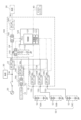
図1は、本実施形態における電力制御システム100と外部装置との電気的構成を示す説明図である。図1には、外部装置として、太陽光発電装置10と、商用電源(系統)20と、負荷30と、マスターコントローラ40と、複数のLIBモジュール50と、が示されており、これらの外部装置と電力制御システム100とが電力供給直流ラインLWを介して電気的に接続されている。負荷30の例としては、製造業で用いられ、比較的高速に加速動作と減速動作とを行う機器(工作機器、産業用ロボット、搬送機器、繊維、食品加工機器など)や、比較的出力が大きく、停電時での動作を必要とする機器(エレベータ、空調機器やコンプレッサなど)が挙げられる。なお、図1では、3つのLIBモジュール50(50A,50B,50C)が例示されている。LIBモジュール50は、蓄電装置の一例である。
A. Embodiments:
A-1. Electrical configuration of the
FIG. 1 is an explanatory diagram showing the electrical configuration of a
太陽光発電装置10は、太陽光エネルギーを電力に変換する太陽光発電を用いて発電する装置であり、ソーラーパネル12とPVコンバータ14とを有する。PVコンバータ14は、発電機器センサ14AとDC/DCコンバータ14Bとを備える。発電機器センサ14Aは、電流電圧センサであり、太陽光発電装置10での発電電力の電圧値と電流値とをそれぞれ検出し、それらの検出結果に応じた検出信号を出力する。DC/DCコンバータ14Bは、発電機器センサ14Aの検出結果に基づき、ソーラーパネル12の発電電力を最大化するように制御を行い、ソーラーパネル12での発電量に応じた直流電力を電力供給直流ラインLWに出力する。以下、太陽光発電装置10から出力される電力を「PV電力Wp」という。なお、本実施形態では、後述のPCU120は、DC/DCコンバータ14Bの動作のオンオフを制御する。ソーラーパネル12は、再生可能エネルギー利用発電装置および電力供給源の一例であり、DC/DCコンバータ14Bは、比例式充放電制御器の一例である。
The solar
商用電源20は、AC/DCコンバータ22を介して電力供給直流ラインLWに電気的に接続されている。商用電源20からの交流電力がAC/DCコンバータ22により直流電力に変換され、電力供給直流ラインLWに出力される。以下、商用電源20から出力される直流電力を「商用電力Wa」という。商用電源20は、電力供給源の一例であり、AC/DCコンバータ22は、比例式充放電制御器の一例である。
The
電力制御システム100は、LICモジュール110と、PCU(POWER CONTROL UNIT)120と、DC/DCコンバータ130と、キャパシタセンサ140と、負荷センサ150と、を備える。
The
LICモジュール110は、複数のリチウムイオンキャパシタ(以下、「LIC」という)112が直列に接続された構成である。LICモジュール110の一端(例えば正極側)は、DC/DCコンバータ等の電圧変換器を介することなく、電力供給直流ラインLWに電気的に接続されている。また、電力供給直流ラインLWには、AC/DCコンバータ22を介して負荷30が電気的に接続されている。すなわち、本実施形態では、LICモジュール110の上記一端側の電位と、負荷30における電力供給直流ラインLWに接続される側の電位とは、略同一である。LICモジュール110の他端(例えば負極側)は、コモンライン(例えばグランドライン)側に電気的に接続されている。なお、電力制御システム100は、負荷30がDC/ACコンバータ160を介して電力供給直流ラインLWに電気的に接続される構成でもよい。以下、負荷30が消費する電力を「負荷電力Wr」という。
The
キャパシタセンサ140は、電力供給直流ラインLWに並列接続されたLICモジュール110に設けられた電流電圧センサ(換言すれば、LICモジュール110と電力供給直流ラインLWとの電流経路に設けられた電流電圧センサ)であり、LICモジュール110の放電時や充電時の電流値および電圧値をそれぞれ検出し、それらの検出結果に応じた検出信号を出力する。負荷センサ150は、電力供給直流ラインLWのうち、LICモジュール110と負荷30との間の電流経路に設けられた電流電圧センサであり、負荷30の電圧値と、負荷30に流れる電流値とをそれぞれ検出し、それらの検出結果に応じた検出信号を出力する。
The
DC/DCコンバータ130の一端は、電力供給直流ラインLWに電気的に接続されており、DC/DCコンバータ130の他端は、接続部132に電気的に接続されている。接続部132には、LIBモジュール50の一端(例えば正極側)が電気的に接続されている。LIBモジュール50の他端(例えば負極側)は、コモンライン(例えばグランドライン)側に電気的に接続されている。LIBモジュール50は、電力供給源および蓄電装置の一例であり、DC/DCコンバータ130は、比例式充放電制御器の一例である。
One end of the DC/
LIBモジュール50は、上記LICモジュール110に比べて出力密度(「電力密度」ともいう)が低いエネルギーストレージ媒体である。また、LIBモジュール50は、LICモジュール110に比べてエネルギー密度が高い。本実施形態では、LIBモジュール50は、例えば、複数のリチウムイオン電池(以下、「LIB」という)52が直列に接続された構成である。LIB52は、例えばリン酸鉄系のLIBや3元系(ニッケルマンガンコバルト系等)のLIBである。以下、LIBモジュール50に蓄積された電力を「ストレージ電力Ws」という。
The
PCU120は、制御部121と、記憶部122と、インターフェース部123とを備え、これらの各部が、バス(図示しない)を介して互いに通信可能に接続されている。
The
制御部121は、例えばCPU等により構成され、記憶部122から読み出したコンピュータプログラムを実行することにより、各比例式充放電制御器を制御する。具体的には、制御部121は、AC/DCコンバータ22、PVコンバータ14のDC/DCコンバータ14BやDC/DCコンバータ130(130A,130B,130C)の動作を制御する。例えば、制御部121は、記憶部122から電力制御プログラム(図示しない)を読み出して実行することにより、後述の電力制御処理を実行する。
The
記憶部122は、例えばROMやRAM、ハードディスクドライブ(HDD)等により構成され、各種のデータ、プログラムやモデルを記憶したり、各種のプログラムやモデルを実行する際の作業領域やデータの一時的な記憶領域として利用されたりする。また、記憶部122には、電力制御プログラムが格納されている。電力制御プログラムは、後述の電力制御処理を実行するためのコンピュータプログラムである。これらのプログラムは、例えば、CD-ROMやDVD-ROM、USBメモリ等のコンピュータによって読み取り可能な記録媒体(不図示)に格納された状態で提供され、PCU120にインストールすることにより記憶部122に格納される。
The
インターフェース部123は、例えばLANインターフェースやUSBインターフェース等により構成され、有線または無線により他の装置との通信を行う。なお、PCU120は、LICモジュール110におけるLIC112やLIBモジュール50におけるLIB52の電流、電圧や温度等を検出して、その検出結果に基づきLIC112やLIB52の状態(例えば過放電、過充電や高温等の異常状態の発生の有無など)を監視する。
The
マスターコントローラ40は、電力制御システム100に通信可能に接続される外部装置であり、PCU120に各種のモード選択信号等を送信する。
The
電力制御システム100が起動されると、PCU120は、電力供給部(太陽光発電装置10、商用電源20)からの供給電力(PV電力Wp、商用電力Wa)を利用して負荷30への電力供給を行いつつ、LIBモジュール50の充放電を制御する電力制御処理を実行する。なお、上述したようにLIBモジュール50の充放電が制御されることにより、LICモジュール110の充放電が間接的に制御される。具体的には、PCU120は、マスターコントローラ40からのモード選択信号や各種センサ14A,140,150に基づき電力制御処理を実行する。その際、PCU120は、例えばDC/DCコンバータ130を動作させてLIBモジュール50の充放電を制御するが、LICモジュール110の充放電を直接には制御しない。すなわち、PCU120は、LIBモジュール50の充放電を制御することにより、LICモジュール110の充放電を間接的に制御する。なお、本明細書において「充放電」とは、充電と放電との両方を意味する場合と、充電および放電のいずれか一方だけを意味する場合とがある。
When the
A-2.比例式充放電制御器の直流電圧フィードバック制御の相互干渉の抑制:
電力制御システム100は、比例式充放電制御器の直流電圧フィードバック制御の相互干渉を抑制するための構成を有している。上述したように、本実施形態では、比例式充放電制御器は、商用電源20に接続されているAC/DCコンバータ22と、ソーラーパネル12に接続されているDC/DCコンバータ14Bと、LIBモジュール50に接続されているDC/DCコンバータ130とである(図1参照)。これらの複数の比例式充放電制御器(22,14B、130)は、制御部121によって制御される。
A-2. Suppression of mutual interference of DC voltage feedback control of proportional charge/discharge controller:
The
ここで、仮に、制御部121が、複数の比例式充放電制御器に対して、個別に直流電圧フィードバック制御を行うと、互いの制御タイミングや制御量のずれ等に起因する相互干渉が発生するおそれがある。直流電圧フィードバック制御の相互干渉が発生すると、例えば、電力供給直流ラインLWの電圧の予期せぬ変動に起因して太陽光発電装置10による発電が停止し、太陽光エネルギーを有効に活用できなくなることがある。すなわち、太陽光発電装置10による発電の停止により、太陽光エネルギーを電力に変換して活用することができなくなる。
Here, if the
これに対して、本実施形態では、電力供給直流ラインLWに対して、LICモジュール110を負荷30との直流換算による電位差が変動しないように接続し、複数の比例式充放電制御器のうちの1つの特定制御器だけに対して直流電圧フィードバック制御を行う構成とされている(図1参照)。この構成によれば、直流電圧フィードバック制御の相互干渉の発生を抑制しつつ複数の比例式充放電制御器を制御することが可能である。
In contrast, in this embodiment, the
すなわち、電力供給直流ラインLWに対して、LICモジュール110が負荷30との直流換算による電位差が変動しないように接続されているため、電力供給直流ラインLWの電圧の時間的変化(応答、振幅)がLICモジュール110の容量に応じて小さくなる。例えば、負荷30の電圧の急激な変動に対して電力供給直流ラインLWの電圧が緩やかに変動する。このため、特定制御器だけに対して直流電圧フィードバック制御を行う構成を採用しても、電力供給直流ラインLWの電圧の変動が他の比例式充放電制御器に対する制御に与える影響を抑制することができる。しかも、本実施形態では、上述したように、LICモジュール110の静電容量は、瞬時変動に対する電力供給直流ラインLWの電圧変動量を「0」に近づける程度に大きい容量に設定されている。このため、負荷電力の変動に対して、電力供給直流ラインLWの電圧変動の応答が、より確実に遅くなり、また、電力供給直流ラインLWの電圧変動量が、より確実に小さくなる。これにより、電力供給直流ラインLWの電圧の変動が他の比例式充放電制御器に対する制御に与える影響を、より効果的に抑制することができる。
That is, since the
PCU120は、複数の比例式充放電制御器のうち、特定制御器を除く他の比例式充放電制御器に対して、ストレージ電力WsおよびPV電力Wpに基づき出力電流値を目標電流値に近づける(直流)電流フィードバック制御を行う。なお、PCU120は、他の比例式充放電制御器の少なくとも1つに対して、ストレージ電力Wsおよび発電出力値Wp1に基づき出力電力値を目標電力値に近づける(直流)電力フィードバック制御を行うとしてもよい。このような制御を行うことにより、他の比例式充放電制御器に接続される電力供給源を、負の負荷(負荷の一部)として扱うことができる。
The
A-3.PCU120の制御部121が実行する電力制御処理:
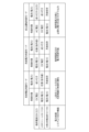
図2は、PCU120の制御部121が実行する電力制御処理を示すフローチャートであり、図3は、各電力供給モードにおける各比例式充放電制御器の制御内容を示す説明図である。本電力制御処理は、特定制御器だけに対して直流電圧フィードバック制御を行いつつ、その特定制御器を、一の比例式充放電制御器から別の一の比例式充放電制御器に切り替える処理である。
A-3. Power control process executed by the
Fig. 2 is a flowchart showing the power control process executed by the
図2に示すように、制御部121は、自立運転条件が満たされるか否かを判断する(S110)。自立運転条件とは、電力制御システム100が自立運転を行うための条件であり、例えば、停電時など、商用電源20が電力供給直流ラインLWから切り離された非系統連携時であることである。
As shown in FIG. 2, the
A-3-1.系統連携時:
商用電源20が電力供給直流ラインLWに接続されている系統連携時には、制御部121は、自立運転条件が満たされないと判断し(S110:NO)、次に、系統電力制御条件が満たされるか否かを判断する(S120)。系統電力制御条件は、商用電源20のAC/DCコンバータ22に対して、電力フィードバック制御を行うための条件である。
A-3-1. When connected to the grid:
In the case of grid-connected operation in which the
制御部121は、系統電力制御条件が満たされないと判断した場合(S120:NO)、系統電圧制御モードを実行する(S130)。系統電圧制御モードでは、制御部121は、商用電源20のAC/DCコンバータ22に対して直流電圧フィードバック制御を行う(図3参照 電圧制御処理の一例)。このとき、商用電源20に流れる電流は成り行きとなるため、電力制御システム100は、商用電源20からの供給電力(または余剰電力による商用電源20への回収電力)を制御することができない。また、このとき、AC/DCコンバータ22は、特定制御器の一例である。
If the
また、系統電圧制御モードでは、制御部121は、複数のLIBモジュール50(50A,50B,50C)のDC/DCコンバータ130(130A,130B,130C)の少なくとも一部に対して、電流フィードバック制御または電力フィードバック制御を行う(図3、後述の図4のS250参照))。これにより、少なくとも一部のLIBモジュール50のDC/DCコンバータ130に対して、電流フィードバック制御または電力フィードバック制御による充放電を行うことができる。また、制御部121は、太陽光発電装置10のDC/DCコンバータ14Bに対して、電流フィードバック制御または電力フィードバック制御を行う(図3参照)。なお、このとき、太陽光発電装置10に流れる電流または電力は、天候に依存して変動する。このように、系統電圧制御モードでは、全てのLIBモジュール50のDC/DCコンバータ130が、直流電圧フィードバック制御の対象外であるため、全てのLIBモジュール50を対象として充放電量を制御可能である。
In addition, in the system voltage control mode, the
制御部121は、系統電力制御条件が満たされると判断した場合(S120:YES)、系統電力制御モードを実行する(S140)。系統電力制御モードでは、制御部121は、商用電源20のAC/DCコンバータ22を、特定制御器(直流電圧フィードバック制御)の対象から外し、電流フィードバック制御または電力フィードバック制御を行う(図3参照)。これにより、電力制御システム100は、商用電源20からの供給電力(または余剰電力による商用電源20への回収電力)を制御することができる。
When the
また、系統電力制御モードでは、制御部121は、複数のLIBモジュール50(50A,50B,50C)のDC/DCコンバータ130(130A,130B,130C)のうちの1つだけに対して、直流電圧フィードバック制御を行う(図3参照 電圧制御処理の一例)。その1つのDC/DCコンバータ130は、特定制御器の一例である。また、制御部121は、直流電圧フィードバック制御の対象とされなかった残りのDC/DCコンバータ130に対して、電流制御または電力制御による充放電を行うことができる(後述の図4のS240参照)。なお、太陽光発電装置10のDC/DCコンバータ14Bについては、上記系統電圧制御モードと同じである。このように、系統電力制御モードでは、商用電源20に対する電力制御を可能とするために、複数のLIBモジュール50のDC/DCコンバータ130の1つが、直流電圧フィードバック制御の対象とされ、電流制御または電力制御による充放電が制約される。
In addition, in the grid power control mode, the
A-3-2.非系統連携時:
商用電源20が電力供給直流ラインLWから切り離された非系統連携時には、制御部121は、自立運転条件が満たされると判断した場合(S110:YES)、自立運転制御モードを実行する(S150)。自立運転制御モードは、太陽光発電装置10のPV電力Wpと、LIBモジュール50のストレージ電力Wsとを利用して、負荷30への電力供給を行うとともに、PV電力Wpの余剰電力(=Wp-Wr)を利用してLIBモジュール50への充電を行うモードである。このとき、AC/DCコンバータ22のAC電流は、負荷30への供給電力に応じて成り行きとなる。
A-3-2. When not connected to the grid:
In the non-grid-connected state in which the
また、自立運転制御モードでは、上記系統電力制御モードと同様、制御部121は、複数のLIBモジュール50(50A,50B,50C)のDC/DCコンバータ130(130A,130B,130C)のうちの1つだけに対して、直流電圧フィードバック制御を行う(図3参照 電圧制御処理の一例)。また、制御部121は、直流電圧フィードバック制御の対象とされなかった残りのDC/DCコンバータ130に対して、電流制御または電力制御による充放電を行うことができる(図4のS240参照)。なお、太陽光発電装置10のDC/DCコンバータ14Bについては、上記系統電圧制御モードと同じである。
In addition, in the independent operation control mode, similar to the grid power control mode, the
本実施形態では、太陽光発電装置10のDC/DCコンバータ14Bは、いずれのモードでも、直流電圧フィードバック制御の対象とされない。上述したように、DC/DCコンバータ14Bは、ソーラーパネル12の発電電力を最大化するように制御する必要があるため、直流電圧フィードバック制御により電流(電力)が成り行きになることを避けることが好ましい。
In this embodiment, the DC/
各モードの実行開始後、制御部121は、停止指示があるか否かを判断する(S160)。停止指示は、例えば、制御部121がマスターコントローラ40から受ける場合もあれば、制御部121が、電力制御システム100の各種の異常を検出したときに自主的に出力する場合もある。制御部121は、停止指示を受けていないと判断した場合(S160:NO)、S110に戻り、条件に応じたモードの実行を継続し、停止指示を受けていると判断した場合(S160:YES)、本電力制御処理を終了する。
After starting execution of each mode, the
A-4.PCU120の制御部121が実行するSOC調整処理:
図4は、PCU120の制御部121が実行するSOC調整処理を示すフローチャートである。SOC調整処理は、電力制御システム100に接続された複数のLIBモジュール50間のSOC(State of Charge、充電率)のバラツキを抑制する(均一化する)ための処理である。制御部121は、上記電力制御処理と並行して、本SOC調整処理を所定時間ごとに繰り返し実行する。
A-4. SOC adjustment process executed by the
4 is a flowchart showing the SOC adjustment process executed by the
制御部121は、複数のLIBモジュール50のそれぞれのSOCを推定する(S210)。SOCの推定方法は、各種の公知の方法(例えばOCV(Open Circuit Voltage、開回路電圧)法、電流積算法)を利用できる。次に、制御部121は、上記電力制御処理において、複数のLIBモジュール50のDC/DCコンバータ130のいずれかが特定制御器の対象になるか否かを判断する。具体的には、制御部121は、系統電圧制御モード(図3のS130)の実行中であれば、特定制御器の対象は、商用電源20のAC/DCコンバータ22であるから、複数のDC/DCコンバータ130のいずれも特定制御器の対象ではないと判断する。一方、制御部121は、系統電力制御モードまたは自立運転制御モード(図3のS140,S150)の実行中であれば、複数のDC/DCコンバータ130のいずれかが特定制御器の対象であると判断する。
The
A-4-1.LIBモジュール50が特定制御器の切替対象である場合:
制御部121は、複数のLIBモジュール50のDC/DCコンバータ130のいずれかが特定制御器の対象であると判断した場合(S220:YES)、複数のDC/DCコンバータ130の中から、1つのDC/DCコンバータ130を特定制御器の切替対象(直流電圧フィードバック制御の対象)として選択する(S230)。S230の処理は、選択処理の一例である。本実施形態では、推定されたSOCが基準SOCに最も近いLIBモジュール50のDC/DCコンバータ130を選択する。基準SOCは、例えば次の通りである。SOCは、蓄電状態の評価の一例である。
複数のLIBモジュール50のそれぞれのSOCの平均値
複数のLIBモジュール50のそれぞれのSOCのうち、最高値と最低値との間の中心値
(3)予め定められた固定値(例えば50%)
A-4-1. When the
When the
The average value of the SOC of each of the
制御部121は、特定制御器の切替対象とされなかったDC/DCコンバータ130(以下、「対象外DC/DCコンバータ130」ということがある)を、電流フィードバック制御または電力フィードバック制御の対象とする。制御部121は、対象外DC/DCコンバータ130のそれぞれについて、SOCに基づき、充電を行うか、放電を行うかを決定する(S240)。例えば、次のように決定してもよい。
(1)「SOC>基準SOC」であるLIBモジュール50の対象外DC/DCコンバータ130:放電を行う
(2)「SOC<基準SOC」であるLIBモジュール50の対象外DC/DCコンバータ130:充電を行う
さらに、次の(3)を加えてもよい。
(3)基準SOCとの差が基準範囲内(例えば基準SOCに対して±5%以内)であるLIBモジュール50の対象外DC/DCコンバータ130:充電も放電も行わない
各DC/DCコンバータ130に対する制御内容が決定されると、制御部121は、決定に応じた制御を実施し(S260)、本SOC調整処理を終了する。
The
(1) DC/
(3) DC/
例えば、図1に示す構成において、第1のLIBモジュール50AのSOCが70%で、第2のLIBモジュール50BのSOCが20%で、第3のLIBモジュール50CのSOCが45%であった場合、次のようにそれぞれの制御対象が決定される。第3のLIBモジュール50CのSOCは中位である(基準SOC(例えば50%)に最も近い)ため、第3のLIBモジュール50Cに対する充放電の必要性は最も低い。このため、第3のLIBモジュール50Cの第3のDC/DCコンバータ130Cが、特定制御器の切替対象として選択され、上記電力制御処理における「系統電力制御モード」(S140)「自立運転制御モード」(S150)では、第3のDC/DCコンバータ130Cに対して直流電圧フィードバック制御が行われる。
For example, in the configuration shown in FIG. 1, if the SOC of the
その結果、第1のDC/DCコンバータ130Aと第2のDC/DCコンバータ130Bとが、対象外DC/DCコンバータ130となる。第1のLIBモジュール50AのSOC(70%)は、基準SOCより大きいため、第1のDC/DCコンバータ130Aに放電を行うことが決定され、上記電力制御処理における「系統電力制御モード」「自立運転制御モード」では、第1のDC/DCコンバータ130Aに対して電流フィードバック制御または電力フィードバック制御による放電が行われる。
As a result, the first DC/
第2のLIBモジュール50BのSOC(20%)は、基準SOCより小さいため、第2のDC/DCコンバータ130Bに充電を行うことが決定され、上記電力制御処理における「系統電力制御モード」「自立運転制御モード」では、第2のDC/DCコンバータ130Bに対して電流フィードバック制御または電力フィードバック制御による充電が行われる。これにより、第1のLIBモジュール50AのSOCは低下して第3のLIBモジュール50CのSOCに近づき、第2のLIBモジュール50BのSOCは上昇して第3のLIBモジュール50CのSOCに近づくため、3つのLIBモジュール50A,50B,50CのSOCのバラツキが抑制される。
Since the SOC (20%) of the
A-4-2.LIBモジュール50が特定制御器の切替対象でない場合:
制御部121は、LIBモジュール50のDC/DCコンバータ130が特定制御器の対象ではないと判断した場合(S220:NO)、対象外DC/DCコンバータ130を、電流フィードバック制御または電力フィードバック制御の対象とする。この場合、全てのDC/DCコンバータ130が対象外DC/DCコンバータ130である。制御部121は、対象外DC/DCコンバータ130のそれぞれについて、SOCに基づき、充電を行うか、放電を行うか、充放電しないかを決定する(S250)。例えば、次のように決定してもよい。
(1)基準SOCとの差が基準範囲内(例えば基準SOCに対して±5%以内)であるLIBモジュール50の対象外DC/DCコンバータ130:充電も放電も行わない
(2)「基準SOCとの差が基準範囲外、かつ、SOC>基準SOC」であるLIBモジュール50の対象外DC/DCコンバータ130:放電を行う
(3)「基準SOCとの差が基準範囲外、かつ、SOC<基準SOC」であるLIBモジュール50の対象外DC/DCコンバータ130:充電を行う
各DC/DCコンバータ130に対する制御内容が決定されると、制御部121は、決定に応じた制御を実施し(S260)、本SOC調整処理を終了する。
A-4-2. When the
When the
(1) DC/
例えば、図1に示す構成において、第1のLIBモジュール50AのSOCが54%で、第2のLIBモジュール50BのSOCが47%で、第3のLIBモジュール50CのSOCが25%であった場合、次のようにそれぞれの制御対象が決定される。第1のLIBモジュール50Aと第2のLIBモジュール50BとのSOCは、いずれも、基準SOC(50%)との差が基準範囲内(50%±5%以内)であるため、充放電しないと決定される。第3のLIBモジュール50CのSOCは、基準範囲外であり、基準SOCよりも低いため、充電すると決定される。これにより、第1のLIBモジュール50Aと第2のLIBモジュール50BとのSOCとは基準範囲内に維持され、第3のLIBモジュール50CのSOCは基準SOCに近づくため、3つのLIBモジュール50A,50B,50CのSOCのバラツキが抑制される。
For example, in the configuration shown in FIG. 1, if the SOC of the
A-5.本実施形態の効果:
本実施形態に係る電力制御システムでは、電力供給直流ラインLWに対して、LICモジュール110が負荷30との直流換算による電位差が変動しないように接続されているため、電力供給直流ラインLWの電圧の時間的変化(応答、振幅)がLICモジュール110の容量に応じて小さくなる。例えば、負荷電圧の急激な変動に対して電力供給直流ラインLWの電圧が緩やかに変動する。このため、特定制御器だけに対して直流電圧フィードバック制御を行う構成を採用しても、電力供給直流ラインLWの電圧の変動が他の比例式充放電制御器に対する制御に与える影響を抑制することができる。しかも、直流電圧フィードバック制御の対象である特定制御器が、一の比例式充放電制御器(例えばAC/DCコンバータ22)から別の一の比例式充放電制御器(例えばDC/DCコンバータ130)に切り替えられる。このため、本実施形態によれば、特定制御器が一の比例式充放電制御器に固定された構成に比べて、多様な電力供給パターンで負荷への電力供給を行うことができる。
A-5. Advantages of this embodiment:
In the power control system according to the present embodiment, the
特定制御器(直流電圧フィードバック制御)の切替対象とされた比例式充放電制御器に接続されたLIBモジュール50(以下、「対象LIBモジュール」という)に対して、その間、電流制御による充放電を行うことができない。ここで、仮に、複数の対象LIBモジュール50のうちの1つのLIBモジュール50だけが対象LIBモジュールとされる構成では、その1つのLIBモジュール50だけに対して、電流制御による充放電を行う機会が制約されるといった不具合が生じる。これに対して、本実施形態によれば、複数のLIBモジュール50が対象LIBモジュールとされるため、それらの複数のLIBモジュール50について、特定のLIBモジュール50だけが電流制御による充放電を行う機会が制約されるといった不具合が生じることを抑制することができる。
During this period, the LIB module 50 (hereinafter referred to as the "target LIB module") connected to the proportional charge/discharge controller that is the switching target of the specific controller (DC voltage feedback control) cannot be charged or discharged by current control. If only one
B.変形例:
本発明は、上述の実施形態に限られるものではなく、その要旨を逸脱しない範囲において種々の形態に変形することができ、例えば次のような変形も可能である。
B. Variations:
The present invention is not limited to the above-described embodiment, and can be modified in various forms without departing from the spirit of the invention. For example, the following modifications are also possible.
上記実施形態における電力制御システム100等の構成は、あくまで一例であり、種々変形可能である。例えば上記実施形態では、電力供給源として、太陽光発電装置10と商用電源20とLIBモジュール50とを例示したが、電力供給源は、太陽光以外の再生可能エネルギー(例えば風力、水力、地熱、火力の自然エネルギーなど)を利用して発電する再生可能エネルギー利用発電装置でもよい。また、電力供給源は、例えばガス発電機など、再生可能エネルギーを利用しない発電装置や、商用電源20やLIBモジュール50以外の電力供給源でもよい。
The configuration of the
上記実施形態において、電力制御システム100は、AC/DCコンバータ22とDC/DCコンバータ14BとDC/DCコンバータ130との少なくとも1つを内蔵する構成でもよい。また、電力制御システム100を複数個、直列または並列に接続して使用してもよい。また、電力制御システム100を構成する複数の機器(LICモジュール110、DC/DCコンバータ130等)は、共通の電力供給直流ラインLWに接続されているため、これらの複数の機器は、互いに並列に接続されている。ただし、本電力制御システム100を複数接続する場合には、直列に接続されている機器が存在してもよい。
In the above embodiment, the
上記実施形態では、比例式充放電制御器として、AC/DCコンバータ22とDC/DCコンバータ14BとDC/DCコンバータ130とを例示したが、入力と出力とが比例する比例式の充放電制御器であればよく、例えばAC/DCコンバータとDC/DCコンバータとを組み合わせて構成された比例式充放電制御器などでもよい。なお、比例式充放電制御器には、充電と放電との両方を制御する制御器に限らず、充電と放電との一方だけを制御する制御器が含まれる。
In the above embodiment, the AC/
上記実施形態において、LICモジュール110は、複数のLIC112が並列に接続された構成、あるいは、複数のLIC112が直列および並列に接続された構成でもよいし、LIC112を1つだけ備える構成でもよい。また、上記実施形態では、キャパシタとして、LICモジュール110(LIC112)を例示したが、例えば、電気二重層キャパシタ(EDLC:Electric Double Layer Capacitor)、電解コンデンサでもよい。
In the above embodiment, the
上記実施形態において、LIBモジュール50は、複数のLIB52が並列に接続された構成、あるいは、複数のLIB52が直列および並列に接続された構成でもよいし、LIB52を1つだけ備える構成でもよい。また、上記実施形態では、蓄電装置として、LIBモジュール50(LIB52)を例示したが、例えば鉛蓄電池などの他の種類の蓄電装置でもよい。また、上記実施形態において、電力制御システム100に接続されるLIBモジュール50は、1つでもよいし、2つでもよい、4つ以上でもよい。
In the above embodiment, the
上記実施形態では、LICモジュール110の上記一端側の電位と、負荷30における電力供給直流ラインLWに接続される側の電位とは、略同一であったが、LICモジュール110の上記一端側の電位と、負荷30における電力供給直流ラインLWに接続される側の電位とが異なり、かつ、両電位の差が変動しない構成でもよい。このような構成でも、LICモジュール110は、LIBモジュール50に比べて、電圧と容量との相関性が高いため、専用のDC/DCコンバータを備えなくても、LIBモジュール50の充放電を制御することにより、LICモジュール110の充放電を間接的に制御することができる。
In the above embodiment, the potential of the one end of the
上記実施形態における各種の処理の内容は、あくまで一例であり、種々変形可能である。上記実施形態の図3に示すフローチャーにおいて、S130の処理(系統電圧制御モード)とS140(系統電力制御モード)とS150(自立運転制御モード)とのいずれか1つを実行しない構成でもよい。 The contents of the various processes in the above embodiment are merely examples and can be modified in various ways. In the flowchart shown in FIG. 3 of the above embodiment, any one of the processes of S130 (grid voltage control mode), S140 (grid power control mode), and S150 (independent operation control mode) may not be executed.
上記実施形態では、蓄電状態の評価として、SOCを例示したが、これに限らず、Cレートと放電深度と劣化度合いなどでもよい。また、蓄電状態の評価は、SOCとCレートと放電深度と劣化度合い(例えばSOH、充電回数、充電時間、放電回数、放電時間、充放電回数、充放電時間)との少なくとも2つの総合評価であってもよい。また、蓄電状態の評価は、蓄電装置の温度などでもよい。上記S230の処理において、3つ以上のLIBモジュール50を備える場合、単に、SOCが中位であるLIBモジュール50のDC/DCコンバータ130を、特定制御器の対象としてもよい。逆に言えば、SOCが最高値や最低値であるLIBモジュール50の対象外DC/DCコンバータ130を、特定制御器の対象としないとしてもよい。
In the above embodiment, the SOC is used as an example of the evaluation of the storage state, but it is not limited to this, and C rate, depth of discharge, and degree of deterioration may also be used. The evaluation of the storage state may also be a comprehensive evaluation of at least two of the SOC, C rate, depth of discharge, and degree of deterioration (e.g., SOH, number of charges, charge time, number of discharges, discharge time, number of charges and discharges, and charge and discharge time). The evaluation of the storage state may also be the temperature of the storage device. In the process of S230 above, when three or
上記実施形態において、ハードウェアによって実現されている構成の一部をソフトウェアに置き換えるようにしてもよく、反対に、ソフトウェアによって実現されている構成の一部をハードウェアに置き換えるようにしてもよい。 In the above embodiment, some of the configurations realized by hardware may be replaced by software, and conversely, some of the configurations realized by software may be replaced by hardware.
10:太陽光発電装置 12:ソーラーパネル 14:PVコンバータ 14A:発電機器センサ 14B:DC/DCコンバータ 20:商用電源 22:AC/DCコンバータ 30:負荷 40:マスターコントローラ 50:LIBモジュール 52:LIB 100:電力制御システム 110:LICモジュール 112:LIC 120:PCU 121:制御部 122:記憶部 123:インターフェース部 130:DC/DCコンバータ 132:接続部 140:キャパシタセンサ 150:負荷センサ 160:DC/ACコンバータ LW:電力供給直流ライン
10: Photovoltaic power generation device 12: Solar panel 14:
Claims (5)
前記電力供給直流ラインに対して、前記負荷との直流換算による電位差が変動しないように電気的に接続されるキャパシタと、
前記複数の比例式充放電制御器を制御する制御部と、を備え、
前記制御部は、
前記複数の比例式充放電制御器のうちの1つの特定制御器に対して、前記電力供給直流ラインの電圧を目標電圧に近づける直流電圧フィードバック制御を行う電圧制御処理と、
前記特定制御器を、一の前記比例式充放電制御器から別の一の前記比例式充放電制御器に切り替える切替処理と、を行う、電力制御システム。 A power control system connected to a power supply DC line to which a load is connected and a plurality of proportional charge/discharge controllers each connected to a plurality of power supply sources including a renewable energy power generation device, a power storage device, and a commercial power source,
a capacitor electrically connected to the power supply DC line so that a potential difference in DC conversion between the power supply line and the load does not fluctuate;
A control unit that controls the plurality of proportional charge/discharge controllers;
The control unit is
a voltage control process for performing DC voltage feedback control for one specific controller among the plurality of proportional charge/discharge controllers to make the voltage of the power supply DC line approach a target voltage;
and a switching process for switching the specific controller from one of the proportional charge/discharge controllers to another of the proportional charge/discharge controllers.
前記複数の電力供給源は、複数の前記蓄電装置を含み、
前記制御部は、前記切替処理において、前記特定制御器の切替対象に、前記複数の蓄電装置のそれぞれに接続される前記比例式充放電制御器を含む、電力制御システム。 2. The power control system of claim 1,
the plurality of power supply sources include a plurality of the power storage devices,
A power control system, wherein the control unit, in the switching process, includes the proportional charge/discharge controllers connected to each of the plurality of power storage devices as switching targets of the specific controller.
前記制御部は、
前記複数の蓄電装置のうち、SOCとCレートと放電深度と劣化度合いとの少なくとも1つに基づく蓄電状態の評価の高低に基づき、一の前記蓄電装置を選択する選択処理を実行し、
前記切替処理では、前記特定制御器を、前記複数の蓄電装置のうち、前記選択処理にて選択された前記蓄電装置に接続された前記比例式充放電制御器に優先的に切り替える、電力制御システム。 3. The power control system of claim 2,
The control unit is
executing a selection process for selecting one of the plurality of power storage devices based on a level of an evaluation of a power storage state based on at least one of an SOC, a C rate, a depth of discharge, and a degree of deterioration;
In the switching process, the specific controller is preferentially switched to the proportional charge/discharge controller connected to the storage device selected in the selection process from among the plurality of storage devices.
前記複数の電力供給源は、3つ以上の前記蓄電装置を含み、
前記蓄電状態の評価は、前記蓄電装置のSOCであり、
前記制御部は、
前記選択処理において、前記複数の蓄電装置のうち、前記SOCが中位である前記蓄電装置を選択する、電力制御システム。 4. The power control system of claim 3,
the plurality of power supply sources include three or more of the power storage devices,
The evaluation of the charge state is an SOC of the charge storage device,
The control unit is
In the selection process, the power storage device having a middle SOC is selected from among the plurality of power storage devices.
前記制御部は、
複数の蓄電装置に接続される前記比例式充放電制御器が前記特定制御器とされていない場合、前記複数の前記蓄電装置について、SOCとCレートと放電深度と劣化度合いとの少なくとも1つに基づく蓄電状態の評価のバラツキが抑制されるように前記複数の前記蓄電装置の少なくとも1つに対して直流電流フィードバック制御を行う電流制御処理を行う、電力制御システム。 3. The power control system of claim 2,
The control unit is
A power control system that performs a current control process to perform DC current feedback control on at least one of the plurality of power storage devices so as to suppress variation in evaluation of the storage state of the plurality of power storage devices based on at least one of SOC, C rate, discharge depth, and degree of deterioration when the proportional charge/discharge controller connected to the plurality of power storage devices is not designated as the specific controller.
Priority Applications (1)
| Application Number | Priority Date | Filing Date | Title |
|---|---|---|---|
| PCT/JP2023/030089 WO2025041247A1 (en) | 2023-08-22 | 2023-08-22 | Electric power control system |
Applications Claiming Priority (1)
| Application Number | Priority Date | Filing Date | Title |
|---|---|---|---|
| PCT/JP2023/030089 WO2025041247A1 (en) | 2023-08-22 | 2023-08-22 | Electric power control system |
Publications (1)
| Publication Number | Publication Date |
|---|---|
| WO2025041247A1 true WO2025041247A1 (en) | 2025-02-27 |
Family
ID=94731836
Family Applications (1)
| Application Number | Title | Priority Date | Filing Date |
|---|---|---|---|
| PCT/JP2023/030089 Pending WO2025041247A1 (en) | 2023-08-22 | 2023-08-22 | Electric power control system |
Country Status (1)
| Country | Link |
|---|---|
| WO (1) | WO2025041247A1 (en) |
Citations (5)
| Publication number | Priority date | Publication date | Assignee | Title |
|---|---|---|---|---|
| WO2012144357A1 (en) * | 2011-04-18 | 2012-10-26 | シャープ株式会社 | Power supply device, control method for power supply device, and dc power supply system |
| JP2015204652A (en) * | 2014-04-11 | 2015-11-16 | 株式会社明電舎 | Power conversion system |
| JP2019030110A (en) * | 2017-07-28 | 2019-02-21 | 住友電気工業株式会社 | Storage battery system and discharge control method thereof |
| WO2021192107A1 (en) * | 2020-03-25 | 2021-09-30 | Tdk株式会社 | Power feeding system and power management device |
| WO2022249377A1 (en) * | 2021-05-27 | 2022-12-01 | 武蔵精密工業株式会社 | Electric power control system |
-
2023
- 2023-08-22 WO PCT/JP2023/030089 patent/WO2025041247A1/en active Pending
Patent Citations (5)
| Publication number | Priority date | Publication date | Assignee | Title |
|---|---|---|---|---|
| WO2012144357A1 (en) * | 2011-04-18 | 2012-10-26 | シャープ株式会社 | Power supply device, control method for power supply device, and dc power supply system |
| JP2015204652A (en) * | 2014-04-11 | 2015-11-16 | 株式会社明電舎 | Power conversion system |
| JP2019030110A (en) * | 2017-07-28 | 2019-02-21 | 住友電気工業株式会社 | Storage battery system and discharge control method thereof |
| WO2021192107A1 (en) * | 2020-03-25 | 2021-09-30 | Tdk株式会社 | Power feeding system and power management device |
| WO2022249377A1 (en) * | 2021-05-27 | 2022-12-01 | 武蔵精密工業株式会社 | Electric power control system |
Similar Documents
| Publication | Publication Date | Title |
|---|---|---|
| TWI774142B (en) | Ac load power supply system and method | |
| CN111628558B (en) | System and method for optimizing energy management and capacity configuration of hybrid energy storage system | |
| CN112510737B (en) | Photovoltaic energy storage charging station grid-connected and off-grid cooperative control method and system | |
| JP6430775B2 (en) | Storage battery device | |
| CN104092278A (en) | Energy management method applied to photovoltaic energy storage system | |
| CN112510756A (en) | Micro-grid optical storage and charging coordinated operation method and system based on power level | |
| CN106786490A (en) | Distributed DC microgrid energy control method | |
| CN105262127A (en) | A power adaptive control method for a photovoltaic power generation hybrid energy storage system | |
| WO2011122681A1 (en) | System-stabilizing system, power supply system, method for controlling central management device, and program for central management device | |
| WO2021192107A1 (en) | Power feeding system and power management device | |
| WO2022110824A1 (en) | Energy scheduling method and apparatus, and system | |
| WO2022172457A1 (en) | Power management device and power supply system | |
| EP3567691B1 (en) | Composite power storage system and power storage method | |
| CN115513932A (en) | Wind-solar energy storage micro-grid control method, system, terminal equipment and storage medium | |
| JP6614010B2 (en) | Battery system | |
| EP4027476B1 (en) | Energy storage system comprising multiple battery packs | |
| JP6768571B2 (en) | Power controller, method and power generation system | |
| WO2022004615A1 (en) | Power converter, method for controlling power converter, power system, method for controlling power system, and program | |
| EP4675877A1 (en) | Energy storage power generation system and control method thereof | |
| WO2025041247A1 (en) | Electric power control system | |
| WO2022249377A1 (en) | Electric power control system | |
| WO2024131045A1 (en) | Photovoltaic apparatus and method for increasing photovoltaic utilization rate of photovoltaic apparatus | |
| JP2024017513A (en) | Distributed power supply system and distributed power supply control method | |
| JP7806214B2 (en) | Power Control System | |
| KR20220000865A (en) | Hybrid charge/discharge system |
Legal Events
| Date | Code | Title | Description |
|---|---|---|---|
| 121 | Ep: the epo has been informed by wipo that ep was designated in this application |
Ref document number: 23949708 Country of ref document: EP Kind code of ref document: A1 |
|
| ENP | Entry into the national phase |
Ref document number: 2025541201 Country of ref document: JP Kind code of ref document: A |
|
| WWE | Wipo information: entry into national phase |
Ref document number: 2025541201 Country of ref document: JP |
|
| WWE | Wipo information: entry into national phase |
Ref document number: 202617019004 Country of ref document: IN |
|
| NENP | Non-entry into the national phase |
Ref country code: DE |