WO2025041202A1 - Dispositif de chauffage en céramique multizone - Google Patents
Dispositif de chauffage en céramique multizone Download PDFInfo
- Publication number
- WO2025041202A1 WO2025041202A1 PCT/JP2023/029889 JP2023029889W WO2025041202A1 WO 2025041202 A1 WO2025041202 A1 WO 2025041202A1 JP 2023029889 W JP2023029889 W JP 2023029889W WO 2025041202 A1 WO2025041202 A1 WO 2025041202A1
- Authority
- WO
- WIPO (PCT)
- Prior art keywords
- zone
- heater circuit
- ceramic
- ceramic plate
- outer zone
- Prior art date
- Legal status (The legal status is an assumption and is not a legal conclusion. Google has not performed a legal analysis and makes no representation as to the accuracy of the status listed.)
- Pending
Links
Images


Classifications
-
- H—ELECTRICITY
- H05—ELECTRIC TECHNIQUES NOT OTHERWISE PROVIDED FOR
- H05B—ELECTRIC HEATING; ELECTRIC LIGHT SOURCES NOT OTHERWISE PROVIDED FOR; CIRCUIT ARRANGEMENTS FOR ELECTRIC LIGHT SOURCES, IN GENERAL
- H05B3/00—Ohmic-resistance heating
- H05B3/20—Heating elements having extended surface area substantially in a two-dimensional [2D] plane, e.g. plate-heater
- H05B3/22—Heating elements having extended surface area substantially in a two-dimensional [2D] plane, e.g. plate-heater non-flexible
- H05B3/28—Heating elements having extended surface area substantially in a two-dimensional [2D] plane, e.g. plate-heater non-flexible heating conductor embedded in insulating material
- H05B3/283—Heating elements having extended surface area substantially in a two-dimensional [2D] plane, e.g. plate-heater non-flexible heating conductor embedded in insulating material the insulating material being an inorganic material, e.g. ceramic
-
- H—ELECTRICITY
- H05—ELECTRIC TECHNIQUES NOT OTHERWISE PROVIDED FOR
- H05B—ELECTRIC HEATING; ELECTRIC LIGHT SOURCES NOT OTHERWISE PROVIDED FOR; CIRCUIT ARRANGEMENTS FOR ELECTRIC LIGHT SOURCES, IN GENERAL
- H05B2203/00—Aspects relating to Ohmic resistive heating covered by group H05B3/00
- H05B2203/002—Heaters using a particular layout for the resistive material or resistive elements
- H05B2203/005—Heaters using a particular layout for the resistive material or resistive elements using multiple resistive elements or resistive zones isolated from each other
-
- H—ELECTRICITY
- H05—ELECTRIC TECHNIQUES NOT OTHERWISE PROVIDED FOR
- H05B—ELECTRIC HEATING; ELECTRIC LIGHT SOURCES NOT OTHERWISE PROVIDED FOR; CIRCUIT ARRANGEMENTS FOR ELECTRIC LIGHT SOURCES, IN GENERAL
- H05B2203/00—Aspects relating to Ohmic resistive heating covered by group H05B3/00
- H05B2203/016—Heaters using particular connecting means
Definitions
- This disclosure relates to a multi-zone ceramic heater.
- Ceramic heaters are used as support stages to uniformly control the temperature of wafers.
- a widely used ceramic heater of this type is one that has a ceramic plate on which the wafer is placed and a cylindrical ceramic shaft attached to the ceramic plate.
- Multi-zone ceramic heaters that have multiple heating zones are also known as ceramic heaters.
- Patent Document 1 JP 2020-191315 A discloses a heating device that includes a first heater electrode arranged in a substantially circular first region and a second heater electrode arranged in a substantially annular second region surrounding the first heater electrode, both in a plate-shaped member.
- This heating device includes a common driver electrode that is electrically connected to all of the heater electrodes and is also electrically connected to a common power supply terminal, and this common driver electrode has a thick portion that is thicker than the thickness of other portions of the common driver electrode. In other words, it discloses that the thickness of the common driver electrode varies partially within its surface.
- Patent document 2 JP 2015-191837 A discloses a laminated heating element having an inner heater and an outer heater around the inner heater.
- This laminated heating element has a ceramic body, a heater built into the body, a terminal attached to one end of the body in the thickness direction, and a power supply path that supplies power from the terminal to the heater.
- the power supply path is composed of a combination of multiple conductive layers and multiple through vias provided in the body.
- conductive layer X which is located closer to the terminal than the heater, has a connection part P with through via ⁇ and a connection part Q with through via ⁇ , and includes at least a part of the path connecting connection part P and connection part Q.
- This conductive layer X has an area AX with a thickness greater than its surroundings.
- Ceramic heaters are required to have small temperature differences (i.e., thermal uniformity) within the surface on which the wafer is placed. In particular, with the recent trend toward finer processing and higher integration, ceramic heaters are required to have even greater thermal uniformity. From this perspective, it is desirable to minimize the temperature difference between the locations where the resistive heating element is present and those where it is not. To achieve this, it is preferable to place the resistive heating element all over the entire area of the ceramic heater, and a promising candidate for this is a printed resistive heating element.
- the inventors have now discovered that in a multi-zone ceramic heater equipped with an inner zone heater circuit, an outer zone heater circuit, and a jumper, by setting the thickness of the jumper within the range of 1.2 to 3.0 times the thickness of the outer zone heater circuit, it is possible to achieve good thermal uniformity while suppressing breakage during manufacturing, etc.
- the object of the present invention is therefore to provide a multi-zone ceramic heater that can achieve good thermal uniformity while minimizing damage during manufacturing, etc.
- a ceramic plate having a circular shape and a first surface on which a wafer is placed and a second surface opposite to the first surface, the ceramic plate including, when viewed from above, an inner zone defined as a circular region within a predetermined distance from a center of the ceramic plate, and an outer zone defined as an annular region outside the inner zone; an inner zone heater circuit embedded in the inner zone of the ceramic plate parallel to the first surface; an outer zone heater circuit embedded in the outer zone of the ceramic plate parallel to the first surface at a depth different from that of the inner zone heater circuit; a pair of first power supply terminals provided at a central portion of the inner zone of the ceramic plate for supplying power to the inner zone heater circuit; a pair of second power supply terminals provided at a central portion of the inner zone of the ceramic plate for supplying power to the outer zone heater circuit; a pair of jumpers separated from each other and embedded in the inner zone of the ceramic plate at the same depth as the outer zone heater circuit and parallel to the first
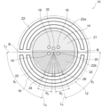
- the outer zone is composed of a plurality of outer subzones partitioned into a circular arc shape, and a linear boundary region, which is not crossed by the outer zone heater circuit, exists between the outer subzones adjacent in the circumferential direction in the radial direction of the ceramic plate so as not to completely divide the outer zone;
- the multi-zone ceramic heater of claim 1 wherein the outer zone heater circuit starts in one or two directions from the first connection portion, and in each starting direction, in a unicursal manner, passes through substantially the entire area of each of the plurality of outer subzones, alternately proceeding in a circumferential direction and turning back just before the boundary region, in a serpentine manner, to reach the second connection portion.
- Aspect 8 Aspect 8.
- each of the inner zone heater circuit, the outer zone heater circuit, and the jumper is in the form of a printed pattern.
- a multi-zone ceramic heater according to any one of the preceding aspects wherein the outer zone heater circuits have a constant thickness in an in-plane direction and the jumpers have a constant thickness in an in-plane direction.
- Aspect 11 Aspect 11.
- the ceramic plate comprises aluminum nitride or aluminum oxide.
- the resistive heating element comprises at least one selected from the group consisting of tungsten, molybdenum, a tungsten-molybdenum alloy, tungsten carbide, a tungsten carbide-titanium nitride composite, and a tungsten carbide-aluminum oxide composite.
- the jumper has a thickness that is 1.8 to 3.0 times the thickness of the outer zone heater circuit.
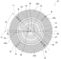
- FIG. 1 is a schematic top view showing an example of a multi-zone ceramic heater according to the present invention.
- FIG. 2 is a schematic cross-sectional view showing the multi-zone ceramic heater shown in FIG. 1.
- FIG. 1 is a schematic top view of a simplified multi-zone ceramic heater for conceptualizing a series circuit.
- FIG. 1 is a schematic top view of a simplified multi-zone ceramic heater for conceptualizing a parallel circuit.
- FIG. 2 is a schematic top view showing another example of a multi-zone ceramic heater, corresponding to Example 1.
- FIG. 11 is a schematic top view showing another example of a multi-zone ceramic heater, corresponding to Examples 2 and 10.
- FIG. 11 is a schematic top view showing another example of a multi-zone ceramic heater, corresponding to Examples 3 and 5.
- FIG. 1 is a schematic top view showing an example of a multi-zone ceramic heater according to the present invention.
- FIG. 2 is a schematic cross-sectional view showing the multi-zone ceramic heater shown in FIG. 1.
- FIG. 11 is a schematic top view showing another example of a multi-zone ceramic heater, corresponding to Examples 4, 7 and 8.
- FIG. 11 is a schematic top view showing another example of a multi-zone ceramic heater, corresponding to Example 6.
- FIG. 11 is a schematic top view showing an example of a multi-zone ceramic heater, corresponding to Example 9 (Comparative Example).
- FIG. 11 is a schematic cross-sectional view showing the multi-zone ceramic heater shown in FIG. 10, corresponding to Example 9 (Comparative Example).
- the multi-zone ceramic heater according to the present invention is a ceramic platform for supporting a wafer in a semiconductor manufacturing device.
- the ceramic heater according to the present invention can be a ceramic heater for a semiconductor film deposition device.
- film deposition devices include CVD (chemical vapor deposition) devices (e.g., thermal CVD devices, plasma CVD devices, photo CVD devices, and MOCVD devices) and PVD (physical vapor deposition) devices.
- the multi-zone ceramic heater 10 shown in Figs. 1 and 2 comprises a ceramic plate 12, an inner zone heater circuit 14, an outer zone heater circuit 16, a pair of first power supply terminals 18, a pair of second power supply terminals 20, and a pair of jumpers 22.
- the ceramic plate 12 is disk-shaped and has a first surface 12a on which a wafer W is placed and a second surface 12b opposite the first surface 12a.
- the ceramic plate 12 includes an inner zone Z1 defined as a circular region within a predetermined distance from the center of the ceramic plate 12, and an outer zone Z2 defined as an annular region outside the inner zone Z1.
- An inner zone heater circuit 14 is embedded in the inner zone Z1 of the ceramic plate 12 parallel to the first surface 12a, while an outer zone heater circuit 16 is embedded in the outer zone Z2 of the ceramic plate 12 parallel to the first surface 12a at a depth different from that of the inner zone heater circuit 14.
- a pair of first power supply terminals 18 are terminals for supplying power to the inner zone heater circuit 14 and are provided in the center of the inner zone Z1 of the ceramic plate 12.
- a pair of second power supply terminals 20 are terminals for supplying power to the outer zone heater circuit 16 and are provided in the center of the inner zone Z1 of the ceramic plate 12.
- a pair of jumpers 22 are separated from each other and embedded in the inner zone Z1 of the ceramic plate 12 parallel to the first surface 12a at the same depth as the outer zone heater circuit 16.
- One of the pair of jumpers 22 electrically connects one of the second power supply terminals 20 to the outer zone heater circuit 16 at a first connection 24, while the other of the pair of jumpers 22 electrically connects the other of the second power supply terminals 20 to the outer zone heater circuit 16 at a second connection 26 at a position different from the first connection 24.
- Each of the inner zone heater circuit 14, the outer zone heater circuit 16, and the jumper 22 is a thin element made of a resistance heating element selected from the group consisting of a printed pattern, a foil, a punched metal, and a mesh.
- the thickness of the jumper 22 is 1.2 to 3.0 times the thickness of the outer zone heater circuit 16.
- the outer zone heater circuit 16 and the jumper 22 by setting the thickness of the jumper 22 within the range of 1.2 to 3.0 times the thickness of the outer zone heater circuit 16, it is possible to achieve good thermal uniformity while suppressing damage during manufacturing, etc.
- ceramic heaters are required to have even greater thermal uniformity (for example, a maximum temperature difference within the surface of 1°C or less). For this reason, it is preferable to place resistance heating elements all over the entire area of the ceramic heater, and a printing type resistance heating element is a promising candidate for this purpose.
- a multi-zone ceramic heater in which a ceramic shaft is placed in the center of a ceramic plate in which a thin resistance heating element (for example, a thickness of 100 ⁇ m or less) is embedded, local hot spots and cool spots are likely to occur in the electrical connection path (jumper connection) from the center of the plate to the resistance heating element on the outer periphery of the plate due to heat generation in the electrical connection path itself.
Landscapes
- Engineering & Computer Science (AREA)
- Chemical & Material Sciences (AREA)
- Ceramic Engineering (AREA)
- Inorganic Chemistry (AREA)
- Resistance Heating (AREA)
- Surface Heating Bodies (AREA)
- Furnace Details (AREA)
- Manufacturing & Machinery (AREA)
Abstract
L'invention concerne un dispositif de chauffage en céramique multizone capable d'obtenir une bonne uniformité thermique tout en supprimant la rupture. Ce dispositif de chauffage en céramique comprend : une plaque en céramique comprenant une zone interne et une zone externe ; un circuit de chauffage de zone interne intégré dans la zone interne ; un circuit de chauffage de zone externe intégré dans la zone externe à une position de profondeur différente de celle du circuit de chauffage de zone interne ; une paire de premières bornes d'alimentation électrique destinées à fournir de l'énergie au circuit de chauffage de zone interne ; une paire de deuxièmes bornes d'alimentation électrique destinées à fournir de l'énergie au circuit de chauffage de zone externe ; et une paire de cavaliers qui sont intégrés dans la zone interne de la plaque en céramique, l'un des cavaliers connectant l'une des deuxièmes bornes d'alimentation électrique et le circuit de chauffage de zone externe au niveau d'une première partie de connexion, et l'autre des deuxièmes bornes d'alimentation électrique et le circuit de chauffage de zone externe au niveau d'une deuxième partie de connexion dans une position différente de la première partie de connexion. Chacun parmi le circuit de chauffage de zone interne, le circuit de chauffage de zone externe et les cavaliers est composé d'un élément chauffant résistif. L'épaisseur des cavaliers est de 1,2 à 3,0 fois l'épaisseur du circuit de chauffage de zone externe.
Priority Applications (6)
| Application Number | Priority Date | Filing Date | Title |
|---|---|---|---|
| PCT/JP2023/029889 WO2025041202A1 (fr) | 2023-08-18 | 2023-08-18 | Dispositif de chauffage en céramique multizone |
| JP2024531409A JP7642159B1 (ja) | 2023-08-18 | 2023-08-18 | マルチゾーンセラミックヒータ |
| KR1020247020214A KR20260039895A (ko) | 2023-08-18 | 2023-08-18 | 멀티 존 세라믹 히터 |
| CN202380014933.3A CN121730018A (zh) | 2023-08-18 | 2023-08-18 | 多区段陶瓷加热器 |
| TW113115607A TW202510629A (zh) | 2023-08-18 | 2024-04-26 | 多分區陶瓷加熱器 |
| US18/675,244 US20250063636A1 (en) | 2023-08-18 | 2024-05-28 | Multizone ceramic heater |
Applications Claiming Priority (1)
| Application Number | Priority Date | Filing Date | Title |
|---|---|---|---|
| PCT/JP2023/029889 WO2025041202A1 (fr) | 2023-08-18 | 2023-08-18 | Dispositif de chauffage en céramique multizone |
Related Child Applications (1)
| Application Number | Title | Priority Date | Filing Date |
|---|---|---|---|
| US18/675,244 Continuation US20250063636A1 (en) | 2023-08-18 | 2024-05-28 | Multizone ceramic heater |
Publications (1)
| Publication Number | Publication Date |
|---|---|
| WO2025041202A1 true WO2025041202A1 (fr) | 2025-02-27 |
Family
ID=94609155
Family Applications (1)
| Application Number | Title | Priority Date | Filing Date |
|---|---|---|---|
| PCT/JP2023/029889 Pending WO2025041202A1 (fr) | 2023-08-18 | 2023-08-18 | Dispositif de chauffage en céramique multizone |
Country Status (6)
| Country | Link |
|---|---|
| US (1) | US20250063636A1 (fr) |
| JP (1) | JP7642159B1 (fr) |
| KR (1) | KR20260039895A (fr) |
| CN (1) | CN121730018A (fr) |
| TW (1) | TW202510629A (fr) |
| WO (1) | WO2025041202A1 (fr) |
Citations (6)
| Publication number | Priority date | Publication date | Assignee | Title |
|---|---|---|---|---|
| JP2015191837A (ja) * | 2014-03-28 | 2015-11-02 | 日本特殊陶業株式会社 | 積層発熱体 |
| WO2017170374A1 (fr) * | 2016-03-29 | 2017-10-05 | 日本碍子株式会社 | Dispositif de chauffage de mandrin électrostatique |
| JP2018056332A (ja) * | 2016-09-29 | 2018-04-05 | 日本特殊陶業株式会社 | 加熱装置 |
| WO2019008889A1 (fr) * | 2017-07-07 | 2019-01-10 | 住友電気工業株式会社 | Socle de montage de substrat servant à chauffer un substrat semi-conducteur |
| WO2020027047A1 (fr) * | 2018-07-31 | 2020-02-06 | 京セラ株式会社 | Appareil de chauffage |
| JP2020191315A (ja) * | 2019-05-20 | 2020-11-26 | 日本特殊陶業株式会社 | 保持装置 |
-
2023
- 2023-08-18 WO PCT/JP2023/029889 patent/WO2025041202A1/fr active Pending
- 2023-08-18 CN CN202380014933.3A patent/CN121730018A/zh active Pending
- 2023-08-18 KR KR1020247020214A patent/KR20260039895A/ko active Pending
- 2023-08-18 JP JP2024531409A patent/JP7642159B1/ja active Active
-
2024
- 2024-04-26 TW TW113115607A patent/TW202510629A/zh unknown
- 2024-05-28 US US18/675,244 patent/US20250063636A1/en active Pending
Patent Citations (6)
| Publication number | Priority date | Publication date | Assignee | Title |
|---|---|---|---|---|
| JP2015191837A (ja) * | 2014-03-28 | 2015-11-02 | 日本特殊陶業株式会社 | 積層発熱体 |
| WO2017170374A1 (fr) * | 2016-03-29 | 2017-10-05 | 日本碍子株式会社 | Dispositif de chauffage de mandrin électrostatique |
| JP2018056332A (ja) * | 2016-09-29 | 2018-04-05 | 日本特殊陶業株式会社 | 加熱装置 |
| WO2019008889A1 (fr) * | 2017-07-07 | 2019-01-10 | 住友電気工業株式会社 | Socle de montage de substrat servant à chauffer un substrat semi-conducteur |
| WO2020027047A1 (fr) * | 2018-07-31 | 2020-02-06 | 京セラ株式会社 | Appareil de chauffage |
| JP2020191315A (ja) * | 2019-05-20 | 2020-11-26 | 日本特殊陶業株式会社 | 保持装置 |
Also Published As
| Publication number | Publication date |
|---|---|
| JP7642159B1 (ja) | 2025-03-07 |
| JPWO2025041202A1 (fr) | 2025-02-27 |
| US20250063636A1 (en) | 2025-02-20 |
| TW202510629A (zh) | 2025-03-01 |
| CN121730018A (zh) | 2026-03-24 |
| KR20260039895A (ko) | 2026-03-23 |
Similar Documents
| Publication | Publication Date | Title |
|---|---|---|
| KR100859061B1 (ko) | 정전 척 | |
| KR100497016B1 (ko) | 가열 장치 | |
| TWI713408B (zh) | 陶瓷加熱器 | |
| JP6715699B2 (ja) | セラミックスヒータ | |
| JP7783391B2 (ja) | ウエハ載置台 | |
| WO2020153086A1 (fr) | Élément chauffant en céramique | |
| JP7642159B1 (ja) | マルチゾーンセラミックヒータ | |
| JP2018005998A (ja) | セラミックスヒータ | |
| US20180096868A1 (en) | Ceramic heater | |
| US7812289B2 (en) | Ceramic heater | |
| JP7673330B1 (ja) | セラミックヒータ | |
| US20210242046A1 (en) | Ceramic heater | |
| JP7756263B2 (ja) | セラミックヒータ | |
| WO2025158627A1 (fr) | Dispositif de chauffage en céramique | |
| TWI858874B (zh) | 靜電吸盤 | |
| WO2025163850A1 (fr) | Dispositif de chauffage en céramique | |
| CN113395793B (zh) | 陶瓷加热器 | |
| JP7471566B2 (ja) | 静電チャック | |
| JP2025173436A (ja) | セラミックヒータ | |
| JP2024119674A (ja) | セラミックスヒータ及びその製造方法 | |
| JP2026008107A (ja) | セラミックヒータ | |
| WO2026038386A1 (fr) | Dispositif de chauffage en céramique | |
| WO2026042328A1 (fr) | Dispositif de chauffage en céramique | |
| WO2025229901A1 (fr) | Support d'échantillon | |
| WO2025134344A1 (fr) | Table de montage de tranche |
Legal Events
| Date | Code | Title | Description |
|---|---|---|---|
| ENP | Entry into the national phase |
Ref document number: 2024531409 Country of ref document: JP Kind code of ref document: A |
|
| WWE | Wipo information: entry into national phase |
Ref document number: 2024531409 Country of ref document: JP |
|
| 121 | Ep: the epo has been informed by wipo that ep was designated in this application |
Ref document number: 23949664 Country of ref document: EP Kind code of ref document: A1 |
|
| NENP | Non-entry into the national phase |
Ref country code: DE |