WO2025033318A1 - 光ファイバケーブル - Google Patents
光ファイバケーブル Download PDFInfo
- Publication number
- WO2025033318A1 WO2025033318A1 PCT/JP2024/027539 JP2024027539W WO2025033318A1 WO 2025033318 A1 WO2025033318 A1 WO 2025033318A1 JP 2024027539 W JP2024027539 W JP 2024027539W WO 2025033318 A1 WO2025033318 A1 WO 2025033318A1
- Authority
- WO
- WIPO (PCT)
- Prior art keywords
- optical fiber
- fiber cable
- inclusion
- ribbon
- optical
- Prior art date
- Legal status (The legal status is an assumption and is not a legal conclusion. Google has not performed a legal analysis and makes no representation as to the accuracy of the status listed.)
- Pending
Links
Images



Classifications
-
- G—PHYSICS
- G02—OPTICS
- G02B—OPTICAL ELEMENTS, SYSTEMS OR APPARATUS
- G02B6/00—Light guides; Structural details of arrangements comprising light guides and other optical elements, e.g. couplings
- G02B6/44—Mechanical structures for providing tensile strength and external protection for fibres, e.g. optical transmission cables
Definitions
- the present invention relates to optical fiber cables.
- Patent Application No. 2023-128753 filed in Japan on August 7, 2023 are incorporated by reference into this specification and made a part of the description of this specification.
- An optical fiber cable includes a rollable ribbon and a water-stopping yarn disposed between the ribbon (see, for example, Patent Document 1).
- the waterstop yarn is arranged between the ribbons so that a part of the waterstop yarn protrudes from the ribbon, and the waterstop yarn may easily jump out from the ribbon. This may cause the waterstop yarn to move inside the optical fiber cable and affect the characteristics of the optical fiber cable.
- the problem that this invention aims to solve is to provide an optical fiber cable that can reduce the impact on the characteristics of the optical fiber cable caused by the movement of inclusions.
- Aspect 1 of the present invention is an optical fiber cable comprising a first optical fiber tape, a first inclusion, and a sheath that houses the first optical fiber tape and the first inclusion, in which the first optical fiber tape contacts the first inclusion at multiple contact points in an orthogonal cross section perpendicular to the longitudinal direction of the optical fiber cable, and the first optical fiber tape surrounds the entire circumference of the first inclusion with one piece of sheath.
- Aspect 2 of the present invention is an optical fiber cable according to aspect 1, in which, in the orthogonal cross section, the trajectory of the first optical fiber tape has a shape with a plurality of convex portions protruding toward the first inclusion, the trajectory is a virtual line that connects the plurality of optical fibers constituting the first optical fiber tape from a first end to a second end of the first optical fiber tape in accordance with the arrangement of the plurality of optical fibers, and the contact point may be an optical fiber cable that includes a portion of the convex portions.
- Aspect 3 of the present invention is an optical fiber cable according to aspect 1 or 2, in which, in the orthogonal cross section, the first optical fiber ribbon includes an enclosing portion that encloses the first inclusion, and first and second terminal portions connected to the enclosing portion, and the first and second terminal portions may be folded inward or outward with respect to the enclosing portion.
- Aspect 4 of the present invention may be an optical fiber cable according to any one of aspects 1 to 3, in which the first optical fiber tape includes a plurality of sub-tape core wires, each of which includes two or more optical fibers, and the plurality of sub-tape core wires are intermittently connected in the longitudinal direction of the first optical fiber tape core wire.
- Aspect 5 of the present invention may be an optical fiber cable in which, in any one of aspects 1 to 4, the total length of the first optical fiber ribbon core in the orthogonal cross section is four times or more the perimeter of the first inclusion.
- the first intermediate material may be an optical fiber cable having water absorption properties.
- Aspect 7 of the present invention may be an optical fiber cable according to any one of aspects 1 to 6, in which the optical fiber ribbons are twisted together at a predetermined pitch, the optical fiber cable has a plurality of the orthogonal cross sections, and the orthogonal cross sections are cross sections that are each included within the respective predetermined pitches in the longitudinal direction of the optical fiber cable.
- Aspect 8 of the present invention may be an optical fiber cable according to any one of aspects 1 to 7, the optical fiber cable including a plurality of the first optical fiber tape cores and a plurality of the first inclusions each surrounded by the plurality of first optical fiber tape cores.
- Aspect 9 of the present invention is an optical fiber cable according to any one of aspects 1 to 8, which may be an optical fiber cable having a second inclusion that is not surrounded by the first optical fiber ribbon.
- Aspect 10 of the present invention is an optical fiber cable according to any one of aspects 1 to 9, which may be an optical fiber cable having a second optical fiber ribbon core that does not surround the first inclusion.
- a single first optical fiber ribbon surrounds the entire circumference of the first inclusion, making it possible to suppress movement of the first inclusion and reduce its effect on the characteristics of the optical fiber cable.
- FIG. 1 is a cross-sectional view showing an optical fiber cable according to an embodiment of the present invention.
- FIG. 2(a) is a cross-sectional view showing a first optical fiber unit in an embodiment of the present invention
- FIGS. 2(b) to 2(e) are cross-sectional views showing modified examples of the first optical fiber unit in the embodiment of the present invention.
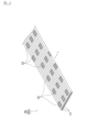
- FIG. 3 is a perspective view showing a first optical fiber ribbon according to an embodiment of the present invention.
- FIG. 4 is an enlarged view of part IV in FIG.
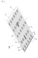
- FIG. 5 is a perspective view showing a modification of the first optical fiber ribbon according to the embodiment of the present invention.
- FIG. 1 is a cross-sectional view of the optical fiber cable 1 in this embodiment
- FIG. 2(a) is a cross-sectional view of the first optical fiber unit 20 in this embodiment
- FIGS. 2(b) to 2(e) are cross-sectional views of the first optical fiber units 20B to 20E which are modified versions of the first optical fiber unit in this embodiment
- FIG. 3 is a perspective view of the first optical fiber ribbon 30 in this embodiment
- FIG. 4 is an enlarged view of part IV in FIG. 2(a).
- FIG. 1 shows a simplified view of the first and second optical fiber units 20, 50
- FIGS. 2(a) to 2(e) show a simplified view of the first optical fiber ribbon 30.
- FIG. 3 shows the first optical fiber ribbon 30 in an unfolded state.
- the optical fiber cable 1 in this embodiment includes an optical fiber assembly 10, a pressure winding 80, a sheath 90, and a tensile member 100.
- This optical fiber cable 1 is a cable that extends in the normal direction to the plane of the paper in Figure 1, and Figure 1 shows a cross section perpendicular to the longitudinal direction of the optical fiber cable 1.
- the configuration of the optical fiber cable 1 is not limited to the above.
- the optical fiber cable 1 may not have the pressure winding 80.
- the optical fiber cable 1 may have a rip cord between the pressure winding 80 and the sheath 90.
- the optical fiber cable 1 may have a reinforcing sheet interposed between the optical fiber assembly 10 and the sheath 90, and this reinforcing sheet may have a corrugated shape.
- the optical fiber cable 1 may have an inner sheath interposed between the optical fiber assembly 10 and the sheath 90.
- the optical fiber cable 1 shown in FIG. 1 has a circular cross-sectional shape, but the cross-sectional shape of the optical fiber cable 1 is not limited to this, and may have a rectangular cross-sectional shape, for example.
- the optical fiber assembly 10 comprises a plurality of (five in this example) first optical fiber units 20, a plurality of (seven in this example) second optical fiber units 50, and a plurality of (two in this example) second inclusions 70.
- the first and second optical fiber units 20, 50 constitute two unit layers 11, 12. That is, the optical fiber assembly 10 comprises an inner unit layer 11 and an outer unit layer 12.
- the inner unit layer 11 is composed of three first optical fiber units 20.
- the inner unit layer 11 is formed by arranging these three optical fiber units 20 in a ring shape.
- the outer unit layer 12 is composed of two first optical fiber units 20 and seven second optical fiber units 50.
- the outer unit layer 12 is formed by arranging these nine optical fiber units 20, 50 in a ring shape.
- the outer unit layer 12 is arranged outside the inner unit layer 11 and surrounds the inner unit layer 11.
- the number of first optical fiber units 20 included in the optical fiber assembly 10 is not particularly limited to the above, and may be, for example, one.
- the number of second optical fiber units 50 included in the optical fiber assembly 10 is also not particularly limited to the above, and the optical fiber assembly 10 may not have a second optical fiber unit 50.
- the number of second inclusions 70 included in the optical fiber assembly 10 is also not particularly limited to the above, and the optical fiber assembly 10 may not have a second inclusion 70.
- the optical fiber assembly 10 may also include, in addition to the first optical fiber units 20, an optical fiber unit in which multiple optical fibers are bundled together with a bundle material.
- the number of the first and second optical fiber units 20, 50 constituting the inner and outer unit layers 11, 12 is not particularly limited to the above.
- the inner unit layer 11 may include the second optical fiber unit 50.
- the outer unit layer 12 includes the first optical fiber unit 20, the inner unit layer 11 may not include the first optical fiber unit 20.
- the outer unit layer 12 may not include the first optical fiber unit 20.
- the outer unit layer 12 may not include the second optical fiber unit 20.
- the optical fiber assembly 10 may not include the layer structure as described above.
- each first optical fiber unit 20 comprises one first optical fiber ribbon 30 and a first inclusion 40.
- the optical fiber assembly 10 may comprise first optical fiber units 20B-20E (see FIG. 2(b)-FIG. 2(e)) described below. Also, the optical fiber assembly 10 may comprise a mixture of the first optical fiber units 20, 20B-20E as multiple first optical fiber units.
- the first optical fiber tape core 30 includes a plurality of optical fibers (optical fiber strands) 31 extending in the longitudinal direction of the optical fiber cable 1.
- the first optical fiber tape core 30 of this embodiment includes 72 optical fibers 31.
- the number N of optical fibers 31 included in the first optical fiber tape core 30 is preferably 48 or more and 144 or less (48 ⁇ N ⁇ 144), and more preferably 60 or more and 108 or less (60 ⁇ N ⁇ 108).
- the first optical fiber tape core wire 30 is an intermittently fixed type optical fiber tape in which the 72 optical fibers 31 are arranged in parallel and intermittently connected. Specifically, adjacent optical fibers 31 are intermittently connected at a predetermined interval by the first connecting portion 32.
- the first connecting portion 32 is formed of, for example, an ultraviolet-curable resin or a thermoplastic resin.
- the first connecting portions 32 adjacent to each other in the longitudinal direction of the first optical fiber tape core wire 30 are arranged shifted in the width direction of the first optical fiber tape core wire 30.
- the area of the first optical fiber tape core wire 30 other than the first connecting portion 32 is a non-connected area in which the adjacent optical fibers 31 are not restrained.
- the first optical fiber tape core wire 30 can be bent at the first connecting portion 32, and a large number of optical fibers 31 can be bundled at a high density.
- the arrangement of the connecting portions 32 is not particularly limited to the above and can be set arbitrarily.
- the spacing between adjacent optical fibers 31 can also be set arbitrarily, and adjacent optical fibers 31 may be in contact with each other.
- the first optical fiber tape 30 may be a continuously fixed optical fiber tape in which multiple optical fibers 31 are bonded over the entire length of the optical fiber tape.
- the connecting portion may have sufficient flexibility so that the first optical fiber tape 30 can be folded as described below, or the connecting portion may be formed when the first optical fiber tape 30 is folded.
- the first inclusion 40 is a fibrous inclusion extending in the longitudinal direction of the optical fiber cable 1. This first inclusion 40 extends along the first optical fiber ribbon core 30.
- This first inclusion 40 is composed of, for example, a yarn made of a resin material such as nylon, polyester (PE), or polypropylene (PP), a yarn made of aramid fiber (aromatic polyamide resin) or glass fiber, or cotton thread.
- This first inclusion 40 has water absorbency to increase the waterproofing of the inside of the optical fiber cable 1. It is noted that the first inclusion 40 does not have to have water absorbency.
- the first optical fiber unit 20 is formed by folding a first optical fiber tape core wire 30 so that the first optical fiber tape core wire 30 surrounds the entire circumference of the first inclusion 40 in a cross section perpendicular to the longitudinal direction of the optical fiber cable 1 (hereinafter also simply referred to as an "orthogonal cross section").
- the first optical fiber tape core wire 30 surrounds the first inclusion 40, movement of the first inclusion 40 within the optical fiber cable 1 can be suppressed.
- the longitudinal direction of the optical fiber cable 1 is both the axial direction of the optical fiber cable 1 and the extension direction of the optical fiber cable 1.
- the first optical fiber tape core wire 30 has a total length sufficient for one piece of the first optical fiber tape core wire 30 to surround the entire circumference of the first inclusion 40.
- the total length of the first optical fiber tape core wire 30 is at least four times the circumference of the first inclusion 40.
- the first optical fiber ribbon 30 includes an enclosing portion 33 and a pair of terminal portions 34, 35.
- the enclosing portion 33 is a portion of the first optical fiber ribbon 30 that encloses the entire circumference of the first inclusion 40.
- the enclosing portion 33 encloses only one circumference of the first inclusion 40 and has an opening 331.
- the opening 331 has a width W1 that is smaller than the width W0 of the first inclusion 40 ( W1 ⁇ W0 ).
- the first terminal portion 34 is a portion from the enclosing portion 33 to a first end (one end) 302 of the first optical fiber ribbon 30.
- the second terminal portion 35 is a portion from the enclosing portion 33 to a second end (the other end) 303 of the first optical fiber ribbon 30.
- the first terminal portion 34 is folded outward relative to the surrounding portion 33, and the second terminal portion 35 is also folded outward relative to the surrounding portion 33.
- the first terminal portion 34 may be folded outward relative to the surrounding portion 33, while the second terminal portion 35 may be folded inward relative to the surrounding portion 33.
- both the first and second terminal portions 34, 35 may be folded inward relative to the surrounding portion 33.
- the first terminal portion 34 may be folded outward relative to the surrounding portion 33, and the second terminal portion 35 may be folded outward relative to the first terminal portion 34 and the surrounding portion 33.
- the surrounding portion 33 surrounds the first inclusion 40, and the terminal portions 34, 35 are folded against the surrounding portion 33, making it easier to unfold the first optical fiber ribbon 30 and remove the first inclusion 40 when the sheath 90 is torn to remove the optical fiber 31.
- first optical fiber tape core wire 30 surrounds the first inclusion 40 is not particularly limited to the above.
- the first optical fiber tape core wire 30 may surround the first inclusion 40 in a spiral shape, as in the first optical fiber unit 20E shown in FIG. 2(e).
- the first optical fiber tape core wire 30 contacts the first inclusion 40 at multiple contact points.
- a convex portion 36 that protrudes toward the first inclusion 40 is formed in the surrounding portion 33 of the first optical fiber tape core wire 30, and the first optical fiber tape core wire 30 contacts the first inclusion 40 at the tip of this convex portion 36.
- the locus 301 of the first optical fiber tape core wire 30 has a shape with a plurality of convex portions 36 protruding toward the first inclusion 40.
- the locus 301 of the first optical fiber tape core wire 30 is a virtual line that connects the plurality of optical fibers 31 constituting the first optical fiber tape core wire 30 from the first end 302 to the second end 303 of the first optical fiber tape core wire 30 according to the arrangement of the plurality of optical fibers 31.
- This locus 301 passes through the centers of the plurality of optical fibers 31 constituting the first optical fiber tape core wire 30.
- this locus 301 is a virtual line formed by connecting unit virtual lines that connect the centers of the adjacent optical fibers 31 via the connecting portion 32 from the first end 302 to the second end 303.
- the convex portion 36 is formed by bending a part of the surrounding portion 33 in the first optical fiber tape core wire 30 into a V-shape and protruding one optical fiber 31a from the optical fibers 31b and 31c on both sides toward the first inclusion 40.
- the optical fiber 31a located at the tip of the convex portion 36 is in contact with the first inclusion 40.
- the shape of the convex portion 36 is less likely to collapse when the tip of the convex portion 36 comes into contact with the first inclusion 40. This makes it possible to stably hold the first inclusion 40 in the first optical fiber tape core wire 30.
- multiple optical fibers 31 may be located at the tip of the convex portion 36, but the number of optical fibers 31 located at this tip is preferably three or less, and more preferably one. Furthermore, when multiple optical fibers 31 are located at the tip of the protrusion 36, at least one of the multiple optical fibers 31 needs to be in contact with the first inclusion 40.
- the first optical fiber unit 20 has two convex portions 36, but the number of convex portions 36 that the first optical fiber unit 20 has is not particularly limited as long as it is multiple.
- the first optical fiber units 20B to 20E have two convex portions 36, but the number of convex portions 36 that the first optical fiber units 20B to 20E have is not particularly limited as long as it is multiple.
- the first optical fiber ribbon 30 may be in contact with the first inclusion 40 at a portion other than the convex portions 36 in the surrounding portion 33.
- the first optical fiber ribbon 30 may be in contact with the first inclusion 40 at a portion in the surrounding portion 33 where the multiple optical fibers 31 are arranged in a straight line or an arc.
- first optical fiber units 20, 20B to 20E shown in Figures 2(a) to 2(e) each have one first inclusion 40
- the first optical fiber unit may have multiple first inclusions 40.
- the multiple first inclusions 40 are surrounded by a single first optical fiber ribbon 30.
- the above-mentioned first optical fiber unit 20 can be manufactured by feeding the optical fiber tape 30 and the first inclusion 40 from their respective feeders and passing them through a jig provided in the molding device.
- the above-mentioned jig is, for example, a former (die) that shapes the cross-sectional shape of the first optical fiber tape 30 into the shape shown in FIG. 2(a) and guides the relative position of the first inclusion 40 with respect to the first optical fiber tape 30 to the position shown in FIG. 2(a).
- the first optical fiber unit 20 is simply a single optical fiber ribbon 30 wrapped around the first inclusion 40.
- multiple bundled optical fiber ribbons are bound with a bundling material or tube, or inserted into the slot grooves of a slot core.
- this known optical fiber unit is a constrained type unit in which multiple optical fiber ribbons are constrained in a standalone state (before being incorporated into the optical fiber cable 1, or after being removed from the optical fiber cable 1).
- the first optical fiber ribbon 30 of this embodiment is not covered with a bundling material or a tube, and is not inserted into the slot groove of the slot core.
- this first optical fiber unit 20 is an open type (unconstrained type) optical fiber unit in which the first optical fiber ribbon 30 is not constrained in a standalone state. Therefore, the optical fiber cable 1 includes an open type optical fiber unit 20 that includes the first optical fiber ribbon 30 and the first inclusion 40.
- an open-type unit as the first optical fiber unit 20
- an open-type unit as the first optical fiber unit 20 not only is the bundling material itself unnecessary, but the winding process is also unnecessary, allowing the line speed to be increased when manufacturing the optical fiber cable 1.
- the outer shape of the first optical fiber unit 20 described above, as shown in FIG. 1, corresponds to the outer shapes of the optical fiber units 20, 50, the second inclusion 70, and the pressure winding 80 adjacent to the first optical fiber unit 20.
- the outer shape of the first optical fiber unit 20 is largely dependent on the outer shapes of the optical fiber units 20, 50, the second inclusion 70, and the pressure winding 80 adjacent to the first optical fiber unit 20, and has a distorted shape. Therefore, the multiple first optical fiber units 20 do not have a specific outer shape, and each has a significantly different outer shape. Note that in FIG. 2(a) to FIG. 2(e), the outer shape of the first optical fiber ribbon 30 is simplified for ease of understanding, so the outer shape of the first optical fiber unit 20 in FIG. 1 does not match the outer shape of the first optical fiber unit 20 in FIG. 2(a).
- the pull-out force PF of the first optical fiber tape 30 from the optical fiber cable 1 is 15 [N/10m] or more and 100 [N/10m] or less (15 [N/10m] ⁇ PF ⁇ 100 [N/10m]).
- This pull-out force PF is the force required to start the relative movement of the optical fiber tape with respect to the optical fiber cable when the optical fiber tape is pulled.
- the tensile force PF is measured as follows. That is, first, a 10 m long optical fiber cable is prepared with the optical fiber ribbon core protruding from both ends. Then, with one end of the optical fiber cable fixed with a fixture, the other ends of the optical fiber ribbon core are held together with the gripping part of the load measuring device and pulled, and the tension is measured when one end of the optical fiber ribbon core starts to move, thereby obtaining the above-mentioned pull-out force PF.
- the second optical fiber unit 50 includes only one second optical fiber tape core 60.
- This second optical fiber unit 50 has the same configuration as the first optical fiber unit 20 described above, except that it does not include an inclusion. In other words, this second optical fiber tape core 60 does not surround the first inclusion 40.
- the second optical fiber tape core 60 has the same configuration as the first optical fiber tape core 30 described above, and as shown in FIG. 3, it is an intermittently fixed optical fiber tape including a plurality of optical fibers (optical fiber strands) 31, and extends in the longitudinal direction of the optical fiber cable 1.
- the second optical fiber unit 50 is formed by folding this second optical fiber tape core 60. Note that a continuously fixed optical fiber tape may be used as this second optical fiber tape core 60.
- This second optical fiber unit 50 is composed of only one optical fiber ribbon 60. Therefore, like the above-mentioned first optical fiber unit 20, this second optical fiber unit 50 is also an open-type optical fiber unit in which the second optical fiber ribbon 60 is not constrained by bundling materials, tubes, slot grooves, etc. Like the above-mentioned first optical fiber unit 20, these multiple second optical fiber units 50 do not have a specific external shape, and each has an external shape that is significantly different from the others.
- the second inclusion 70 is a fibrous inclusion extending in the longitudinal direction of the optical fiber cable 1, similar to the first inclusion 40 described above.
- This second inclusion 70 is not present in the optical fiber units 20, 50, but is interposed between the optical fiber units 20, 50. Specifically, as shown in FIG. 1, this second inclusion 70 is disposed near the center of the optical fiber assembly 10, or is sandwiched between three optical fiber units 20, 50.
- the second inclusion 70 may be sandwiched between two or four or more optical fiber units 20, 50, or between the optical fiber units 20, 50 and the pressure winding 80. In this way, the optical fiber assembly 10 includes the second inclusion 70 that is not surrounded by the first optical fiber ribbon 30, and thus the movement of the optical fiber units 20, 50 in the optical fiber cable 1 can be suppressed.
- the optical fiber assembly 10 is formed by twisting together the first and second optical fiber units 20, 50 and the second inclusion 70 described above.
- Specific examples of the twisting method of the optical fiber assembly 10 include SZ twisting and unidirectional twisting.
- SZ twisting is a method of twisting multiple linear bodies while reversing the twisting direction at predetermined intervals.
- unidirectional twisting is a method of twisting multiple linear bodies in only one twisting direction, that is, a method of twisting multiple linear bodies in a spiral shape.
- the first and second optical fiber units 20, 50 and the second inclusion 70 are twisted at a pitch P.
- the twist pitch P is the distance along the longitudinal direction of the optical fiber cable 1 between these reversal sections.
- the twist pitch P is the distance that the optical fiber assembly 10 advances along the longitudinal direction of the optical fiber cable 1 while the optical fiber assembly 10 rotates 360 degrees due to twisting.
- the cross-sectional structure of the optical fiber assembly 10 described above with reference to Figures 1 to 2(e) and 4 can be confirmed in multiple orthogonal cross sections along the longitudinal direction of the optical fiber cable 1.
- these multiple orthogonal cross sections are cross sections that are each included within the above-mentioned twist pitch P.
- these multiple orthogonal cross sections are cross sections that are individually included within multiple ranges that are connected by the above-mentioned twist pitch P, and one or more of the above orthogonal cross sections are included within one twist pitch P.
- the first optical fiber ribbon 30 is in contact with the first inclusion 40 at multiple contact points.
- the optical fiber assembly 10 is covered with a pressure winding 80.
- the pressure winding 80 is formed by winding a pressure winding tape 81 vertically around the outer circumference of the optical fiber assembly 10.
- the pressure winding tape 81 is wound around the outer circumference of the optical fiber assembly 10 with the longitudinal direction of the pressure winding tape 81 substantially coinciding with the longitudinal direction of the optical fiber cable 1 and the width direction of the pressure winding tape 81 substantially coinciding with the circumferential direction of the optical fiber cable 1.
- the winding method of the pressure winding tape 81 is not limited to longitudinal winding, and may be horizontal winding (spiral winding), for example.
- This holding winding tape 81 is made of a nonwoven fabric or a film.
- the nonwoven fabric that makes up the holding winding tape 81 are not particularly limited, but include nonwoven fabrics made of fibers such as polyester, polyethylene, and polypropylene.
- specific examples of the film that makes up the holding winding tape 81 are not particularly limited, but include films made of resins such as polyethylene (PE), polypropylene (PP), polyethylene terephthalate (PET), polybutylene terephthalate (PBT), and nylon.
- water-absorbing powder may be applied to the nonwoven fabric to make it function as a water-absorbing layer for stopping water from entering the optical fiber cable 1.
- the water-absorbing powder swells and seals the gaps inside the optical fiber cable 1, thereby stopping water from entering the optical fiber cable 1.
- water-absorbing powders include, but are not limited to, highly absorbent starch-based, cellulose-based, polyacrylic acid-based, polyvinyl alcohol-based, and polyoxyethylene-based materials, or mixtures of these.
- the water-absorbing powder can be applied to the nonwoven fabric by adhering (spraying) it onto the surface of the nonwoven fabric, or by placing it between two sheets of nonwoven fabric.
- the sheath (outer jacket) 90 is a tubular member that covers the outer circumference of the pressure winding 80, and the optical fiber assembly 10 wrapped in the pressure winding 80 is housed in the internal space 91 of the sheath 90.
- This sheath 90 is made of a resin material such as polyvinyl chloride (PVC), polyethylene (PE), nylon, ethylene fluoride, or polypropylene (PP).
- PVC polyvinyl chloride
- PE polyethylene
- PP polypropylene
- a pair of tensile members 100 are embedded in this sheath 90.
- the pair of tension members 100 are linear members that bear the stress applied in the longitudinal direction of the optical fiber cable 1, thereby reducing the load on the optical fiber 31.
- the tension members 100 are embedded in the sheath 90 so as to extend substantially parallel to each other across the internal space 91 of the sheath 90. Note that the number and arrangement of the tension members 100 provided in the optical fiber cable 1 are not particularly limited to those described above.
- non-metallic materials examples include, but are not limited to, fiber-reinforced plastics (FRP), such as glass fiber reinforced plastics (GFRP), aramid fiber reinforced plastics (KFRP) reinforced with aramid (aromatic polyamide resin), and polyethylene fiber reinforced plastics reinforced with polyethylene fibers.
- FRP fiber-reinforced plastics
- GFRP glass fiber reinforced plastics
- KFRP aramid fiber reinforced plastics
- metallic materials include, but are not limited to, metal wires such as steel wires.
- one first optical fiber ribbon 30 contacts the first inclusion 40 at the tips of the multiple protrusions 36 and surrounds the entire circumference of the first inclusion 40. This makes it possible to suppress the movement of the first inclusion 40 within the optical fiber cable 1, thereby reducing the impact on the characteristics of the optical fiber cable 1.
- the inclusion may unintentionally wrap around the optical fiber ribbon in places more than necessary, and when the cable expands and contracts due to temperature changes or when the cable is bent, the inclusion may tighten the optical fiber ribbon at those places, worsening the transmission loss.
- the first optical fiber ribbon 30 covers the first inclusion 40, and the movement of the first inclusion 40 is suppressed, so the impact on the transmission loss of the optical fiber cable 1 can be reduced.
- the first optical fiber ribbon core wire 30 covers the first inclusions 40, which suppresses the movement of the first inclusions 40, thereby reducing the impact on the transmission loss of the optical fiber cable 1.
- the first optical fiber ribbon core 30 covers the first inclusions 40, suppressing the movement of the first inclusions 40, thereby reducing the impact on the waterproof performance of the optical fiber cable 1.
- the frictional force between the pressure winding and the optical fiber tape core wire and the frictional force between the optical fiber tape core wires may be adjusted by using an inclusion.
- the inclusion that was in contact only with the optical fiber tape core wire moves between the pressure winding and the optical fiber tape core wire, the pull-out force of the optical fiber tape core wire becomes unstable.
- the first optical fiber tape core wire 30 covers the first inclusion 40, and the movement of the first inclusion 40 is suppressed, so that the effect on the pull-out force of the first optical fiber tape core wire 30 in the optical fiber cable 1 can be reduced.
- the first optical fiber unit 20 may be constructed using a first optical fiber tape core wire 30B shown in FIG. 5.
- FIG. 5 is a perspective view showing the first optical fiber tape core wire 30B, which is a modified example of the first optical fiber tape core wire 30 described above.
- This first optical fiber tape core wire 30B includes multiple sub-tape core wires 37.
- Each sub-tape core wire 37 has the same configuration as the first optical fiber tape core wire 30 described above, except that the number of optical fibers 31 differs.
- each sub-tape core wire 37 is an intermittently fixed type optical fiber tape in which multiple optical fibers 31 are arranged in parallel and intermittently connected at the first connection portion 32.
- the adjacent sub-tape core wires 37 are also intermittently connected at a predetermined interval by the second connection portion 38.
- the second connection portion 38 is formed of, for example, an ultraviolet-curable resin or a thermoplastic resin.
- the areas other than the second connection portion 38 are non-connected areas where the sub-tape core wires 37 are not bound to each other. Since the first optical fiber tape core wire 30B has such a plurality of sub-tape core wires 37, it is possible to make identifiers such as ring marks different for each sub-tape core wire 37, making it easier to identify the optical fibers 31 in the first optical fiber tape core wire 30B.
- a conventional optical fiber tape core wire may be composed of, for example, 4, 8, 12, or 16 optical fibers
- the first optical fiber tape core wire 30B since the first optical fiber tape core wire 30B has a plurality of sub-tape core wires 37, the first optical fiber tape core wire 30B can be handled with the same ease as the above-mentioned conventional optical fiber tape core wire.
- the number of sub-tape core wires 37 included in the first optical fiber tape core wire 30B is not particularly limited to the above, so long as it is more than one. Furthermore, the number of optical fibers 31 included in each sub-tape core wire 37 is not particularly limited, so long as it is two or more. Although not particularly limited, the total number N of optical fibers 31 included in the first optical fiber tape core wire 30B is preferably 48 or more and 144 or less (48 ⁇ N ⁇ 144), and more preferably 60 or more and 108 or less (60 ⁇ N ⁇ 108). Furthermore, a continuous fixed type optical fiber tape may be used as the sub-tape core wire 37.
Landscapes
- Physics & Mathematics (AREA)
- General Physics & Mathematics (AREA)
- Optics & Photonics (AREA)
- Light Guides In General And Applications Therefor (AREA)
- Endoscopes (AREA)
- Insulated Conductors (AREA)
Priority Applications (3)
| Application Number | Priority Date | Filing Date | Title |
|---|---|---|---|
| JP2025539353A JPWO2025033318A1 (https=) | 2023-08-07 | 2024-08-01 | |
| CONC2026/0000200A CO2026000200A2 (es) | 2023-08-07 | 2026-01-09 | Cable de fibra óptica |
| MX2026001115A MX2026001115A (es) | 2023-08-07 | 2026-01-28 | Cable de fibra optica |
Applications Claiming Priority (2)
| Application Number | Priority Date | Filing Date | Title |
|---|---|---|---|
| JP2023128753 | 2023-08-07 | ||
| JP2023-128753 | 2023-08-07 |
Publications (1)
| Publication Number | Publication Date |
|---|---|
| WO2025033318A1 true WO2025033318A1 (ja) | 2025-02-13 |
Family
ID=94533867
Family Applications (1)
| Application Number | Title | Priority Date | Filing Date |
|---|---|---|---|
| PCT/JP2024/027539 Pending WO2025033318A1 (ja) | 2023-08-07 | 2024-08-01 | 光ファイバケーブル |
Country Status (5)
| Country | Link |
|---|---|
| JP (1) | JPWO2025033318A1 (https=) |
| CO (1) | CO2026000200A2 (https=) |
| MX (1) | MX2026001115A (https=) |
| TW (1) | TW202507348A (https=) |
| WO (1) | WO2025033318A1 (https=) |
Citations (6)
| Publication number | Priority date | Publication date | Assignee | Title |
|---|---|---|---|---|
| JP2016075815A (ja) * | 2014-10-07 | 2016-05-12 | 住友電気工業株式会社 | 光ファイバケーブル及び光ファイバケーブルの製造方法 |
| JP2018136376A (ja) * | 2017-02-20 | 2018-08-30 | 株式会社フジクラ | 光ファイバケーブル |
| US20190049681A1 (en) * | 2017-08-08 | 2019-02-14 | Corning Research & Development Corporation | Rollable optical fiber ribbon with low attenuation, large mode field diameter optical fiber and cable |
| JP2019090928A (ja) * | 2017-11-15 | 2019-06-13 | 株式会社フジクラ | 光コード、抗張力体付き光ファイバテープ、及び抗張力体付き光ファイバテープの製造方法 |
| WO2022158496A1 (ja) * | 2021-01-21 | 2022-07-28 | 古河電気工業株式会社 | 光ファイバ、光ファイバテープ心線および光ファイバケーブル |
| WO2023234355A1 (ja) * | 2022-05-31 | 2023-12-07 | 住友電気工業株式会社 | 光ファイバリボン |
-
2024
- 2024-08-01 JP JP2025539353A patent/JPWO2025033318A1/ja active Pending
- 2024-08-01 WO PCT/JP2024/027539 patent/WO2025033318A1/ja active Pending
- 2024-08-06 TW TW113129316A patent/TW202507348A/zh unknown
-
2026
- 2026-01-09 CO CONC2026/0000200A patent/CO2026000200A2/es unknown
- 2026-01-28 MX MX2026001115A patent/MX2026001115A/es unknown
Patent Citations (6)
| Publication number | Priority date | Publication date | Assignee | Title |
|---|---|---|---|---|
| JP2016075815A (ja) * | 2014-10-07 | 2016-05-12 | 住友電気工業株式会社 | 光ファイバケーブル及び光ファイバケーブルの製造方法 |
| JP2018136376A (ja) * | 2017-02-20 | 2018-08-30 | 株式会社フジクラ | 光ファイバケーブル |
| US20190049681A1 (en) * | 2017-08-08 | 2019-02-14 | Corning Research & Development Corporation | Rollable optical fiber ribbon with low attenuation, large mode field diameter optical fiber and cable |
| JP2019090928A (ja) * | 2017-11-15 | 2019-06-13 | 株式会社フジクラ | 光コード、抗張力体付き光ファイバテープ、及び抗張力体付き光ファイバテープの製造方法 |
| WO2022158496A1 (ja) * | 2021-01-21 | 2022-07-28 | 古河電気工業株式会社 | 光ファイバ、光ファイバテープ心線および光ファイバケーブル |
| WO2023234355A1 (ja) * | 2022-05-31 | 2023-12-07 | 住友電気工業株式会社 | 光ファイバリボン |
Also Published As
| Publication number | Publication date |
|---|---|
| MX2026001115A (es) | 2026-03-02 |
| JPWO2025033318A1 (https=) | 2025-02-13 |
| CO2026000200A2 (es) | 2026-01-23 |
| TW202507348A (zh) | 2025-02-16 |
Similar Documents
| Publication | Publication Date | Title |
|---|---|---|
| JP7479533B2 (ja) | スロットレス光ファイバケーブル、スロットレス光ケーブルコアの製造方法 | |
| KR20080027328A (ko) | 광섬유 케이블 및 그 제조방법 | |
| JP7652192B2 (ja) | 光ファイバケーブルおよびコネクタ付きケーブル | |
| CN115516356B (zh) | 光缆 | |
| JP7151727B2 (ja) | 光ファイバケーブル | |
| US11525972B2 (en) | Reticulated tube, optical fiber protective unit, method for protecting optical fiber, and method for manufacturing reticulated tube | |
| AU2022202391B2 (en) | Optical fiber cable | |
| JP7068142B2 (ja) | 光ファイバケーブル | |
| JP7184526B2 (ja) | 光ファイバケーブル | |
| CA3245683A1 (en) | FIBER OPTIC CABLE AND FIBER OPTIC CABLE PRODUCTION METHOD | |
| WO2025033318A1 (ja) | 光ファイバケーブル | |
| JP7609982B2 (ja) | 光ファイバケーブル | |
| JP7068114B2 (ja) | 光ファイバケーブル | |
| WO2023127419A1 (ja) | 光ファイバ集合体、光ファイバケーブル、および光ファイバ集合体の製造方法 | |
| WO2025134902A1 (ja) | 光ファイバケーブル | |
| JP7068131B2 (ja) | 光ファイバケーブル | |
| JP7716505B2 (ja) | 光ケーブル用の光ファイバ集合体及び光ケーブル | |
| WO2023127420A1 (ja) | 光ファイバ集合体、光ファイバケーブル、および光ファイバ集合体の製造方法 | |
| JP2025064526A (ja) | 光ケーブル | |
| WO2025182444A1 (ja) | 光ファイバケーブル | |
| JP2005202106A (ja) | 光ケーブル | |
| WO2023127418A1 (ja) | 光ファイバ集合体、光ファイバケーブル、および光ファイバ集合体の製造方法 | |
| WO2023127421A1 (ja) | 光ファイバ集合体、光ファイバケーブル、および光ファイバ集合体の製造方法 | |
| JPH10133073A (ja) | 光ケーブル |
Legal Events
| Date | Code | Title | Description |
|---|---|---|---|
| 121 | Ep: the epo has been informed by wipo that ep was designated in this application |
Ref document number: 24851743 Country of ref document: EP Kind code of ref document: A1 |
|
| WWE | Wipo information: entry into national phase |
Ref document number: P2026-00060 Country of ref document: AE |
|
| ENP | Entry into the national phase |
Ref document number: 2025539353 Country of ref document: JP Kind code of ref document: A |
|
| WWE | Wipo information: entry into national phase |
Ref document number: 2025539353 Country of ref document: JP |
|
| WWE | Wipo information: entry into national phase |
Ref document number: MX/A/2026/001115 Country of ref document: MX |
|
| REG | Reference to national code |
Ref country code: BR Ref legal event code: B01A Ref document number: 112026002982 Country of ref document: BR |
|
| WWP | Wipo information: published in national office |
Ref document number: MX/A/2026/001115 Country of ref document: MX |
|
| NENP | Non-entry into the national phase |
Ref country code: DE |