WO2025033222A1 - ろ過装置、ろ過システム、及び、ろ過方法 - Google Patents
ろ過装置、ろ過システム、及び、ろ過方法 Download PDFInfo
- Publication number
- WO2025033222A1 WO2025033222A1 PCT/JP2024/026864 JP2024026864W WO2025033222A1 WO 2025033222 A1 WO2025033222 A1 WO 2025033222A1 JP 2024026864 W JP2024026864 W JP 2024026864W WO 2025033222 A1 WO2025033222 A1 WO 2025033222A1
- Authority
- WO
- WIPO (PCT)
- Prior art keywords
- liquid
- filter
- hole
- holding portion
- liquid holding
- Prior art date
- Legal status (The legal status is an assumption and is not a legal conclusion. Google has not performed a legal analysis and makes no representation as to the accuracy of the status listed.)
- Pending
Links
Images

















Classifications
-
- G—PHYSICS
- G01—MEASURING; TESTING
- G01N—INVESTIGATING OR ANALYSING MATERIALS BY DETERMINING THEIR CHEMICAL OR PHYSICAL PROPERTIES
- G01N1/00—Sampling; Preparing specimens for investigation
- G01N1/02—Devices for withdrawing samples
- G01N1/10—Devices for withdrawing samples in the liquid or fluent state
Definitions
- the present invention relates to filtration devices, filtration systems, and filtration methods.
- Patent document 1 discloses a technique for observing, under a microscope, particles suspended in a large amount of liquid at a low concentration.
- Patent document 1 discloses a particle capture device and a particle measurement method in which "a particle capture device for capturing particles contained in liquid has a filtering means 10 including a filtering membrane 11. The filtering means 10 is configured so that liquid flowing into the filtering means 10 passes through a part of the filtering membrane 11.”
- a liquid containing fine particles may be passed through a portion of the filtration membrane to efficiently observe the fine particles on the filtration membrane.
- a large amount of liquid must be passed through. If the area of the filtration membrane through which the liquid passes is small, there is an issue that it takes a long time to filter a large amount of liquid.
- the present invention was made in light of this background, and its objective is to achieve efficient filtration.
- the present invention provides a filter comprising a first liquid holding portion for holding a liquid to be filtered, a first hole being provided on a bottom surface of the first liquid holding portion and a second hole being provided on a surface of the first liquid holding portion other than the bottom surface, a second liquid holding portion communicating with the first liquid holding portion via the first hole, and a third liquid holding portion communicating with the first liquid holding portion via the second hole, wherein a first filter is provided in the first hole and a second filter is provided in the second hole.
- Other solutions will be described in the embodiments as appropriate.
- the present invention makes it possible to achieve efficient filtration.
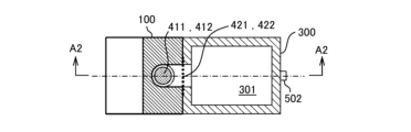
- FIG. 1 is a schematic diagram (part 1) illustrating an example of the configuration of a filtering device according to a first embodiment.
- FIG. 2 is a schematic diagram (part 2) showing an example of the configuration of the filtering device according to the first embodiment.
- FIG. 1 is a diagram illustrating a configuration example of a filtration system.
- FIG. 13 is a diagram showing the disassembly of the filtration device.
- FIG. 1 is a diagram showing a configuration of a first filter;
- FIG. 2 is a diagram (part 2) showing the configuration of the first filter;
- FIG. 1 is a diagram (part 1) showing an outline of filtration of a microparticle suspension using a filtration device.
- FIG. 1 is a schematic diagram (part 1) illustrating an example of the configuration of a filtering device according to a first embodiment.
- FIG. 2 is a schematic diagram (part 2) showing an example of the configuration of the filtering device according to the first embodiment.
- FIG. 1 is a diagram illustrating a configuration
- FIG. 2 is a schematic diagram (part 2) showing filtration of a microparticle suspension using a filtration device.
- FIG. 3 is a schematic diagram (part 3) showing filtration of a microparticle suspension using a filtration device.
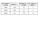
- 13 is a table showing values related to the area of the first hole.
- FIG. 11 is a schematic diagram (part 1) illustrating an example of the configuration of a filtering device according to a second embodiment.
- FIG. 11 is a schematic diagram (part 2) showing an example of the configuration of a filtering device according to a second embodiment.
- FIG. 11 is a schematic diagram (part 3) showing an example of the configuration of the filtering device according to the second embodiment.
- FIG. 4 is a schematic diagram (part 4) showing an example of the configuration of the filtration device according to the second embodiment.
- FIG. 11 is a schematic diagram (part 1) showing an example of the configuration of a filtering device according to a third embodiment.
- FIG. 13 is a schematic diagram (part 2) showing an example of the configuration of the filtration device according to the third embodiment.
- FIG. 13 is a schematic diagram (part 3) showing an example of the configuration of the filtering device according to the third embodiment.
- FIG. 4 is a schematic diagram (part 4) showing an example of the configuration of the filtration device according to the third embodiment.
- FIG. 11 is a schematic diagram (part 1) showing an example of the configuration of a filtering device according to a fourth embodiment.
- FIG. 13 is a schematic diagram (part 2) showing an example of the configuration of the filtering device according to the fourth embodiment.
- FIG. 13 is a schematic diagram (part 3) showing an example of the configuration of a filtering device according to a fourth embodiment.
- 13A and 13B are diagrams showing modified examples regarding the arrangement of the first liquid holding portion.
- FIG. 13 is a diagram (part 1) showing a filtering device according to a fifth embodiment.
- FIG. 13 is a second diagram showing the filtering device according to the fifth embodiment.
- FIG. 13 is a diagram showing an example of the configuration of a filtering device according to a sixth embodiment.
- 2 is a flowchart showing the procedure of a filtration method according to the present embodiment.
- FIG. 1 is a schematic diagram (part 1) for explaining the procedure of the filtration method according to the present embodiment.
- FIG. 2 is a schematic diagram (part 2) for explaining the procedure of the filtration method according to the present embodiment.
- FIG. 3 is a schematic diagram (part 3) for explaining the procedure of the filtration method according to the present embodiment.
- FIG. 4 is a schematic diagram (part 4) for explaining the procedure of the filtration method according to the present embodiment.
- FIG. 5 is a schematic diagram (part 5) for explaining the procedure of the filtration method according to the present embodiment.
- FIG. 6 is a schematic diagram (part 6) for explaining the procedure of the filtration method according to the present embodiment.
- FIG. 7 is a schematic diagram (part 7) for explaining the procedure of the filtration method according to the present embodiment.
- FIG. 8 is a schematic diagram for explaining the procedure of the filtration method according to the present embodiment;
- FIG. 9 is a schematic diagram for explaining the procedure of the filtration method according to the present embodiment.
- FIG. 10 is a schematic diagram for explaining the procedure of the filtration method according to the present embodiment
- FIG. 11 is a schematic diagram showing another example of a filtering device according to a second embodiment.
- 13A and 13B are diagrams showing the configuration of another example of the first filter used in the filtering device according to the second embodiment.
- FIG. 11 is a schematic diagram showing another example of a filtering device according to the third embodiment.
- microparticles 701 includes, but is not limited to, particles formed by pulverization, sintering, crystallization, etc., particles precipitated or generated by chemical reactions, particles generated by external stimuli or factors, organic fibers, microplastics, pollen, cells, blood cells, bacteria, viruses, etc.
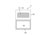
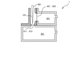
- FIG. 1 and 2 are schematic diagrams showing an example of the configuration of a filtering device 1 according to a first embodiment.
- 1 is a sectional view taken along line A2-A2 in FIG. 2
- FIG. 2 is a sectional view taken along line A1-A1 in FIG.
- the filtration device 1 is composed of a first member 100, a second member 200, and a third member 300.
- the first member 100 which is a first container, has a first liquid holding portion 101 that is a cylindrical space inside and holds a liquid. That is, the first liquid holding portion 101 is provided in the first member 100.
- a solution referred to as a microparticle suspension 700 (see FIG. 7 and FIG. 9)
- microparticles 701 see FIG.
- the cross-sectional shape (transverse cross-sectional shape) of the first liquid holding portion 101 when cut in a direction perpendicular to the axial direction of the first liquid holding portion 101 is substantially circular.
- the transverse cross-sectional shape of the first liquid holding portion 101 is not limited to a circular shape, and may be a polygonal shape.
- a first hole 411 is provided in the bottom surface of the first liquid holding portion 101, and a second hole 421 is provided in a surface (side surface) different from the bottom surface of the first liquid holding portion 101.
- the second member 200 and the third member 300 are a second container that is separate from the first member 100.
- the second member 200 also has a hollow second liquid holding portion 201 inside.
- the second liquid holding portion 201 can store liquid inside.
- the liquid stored in the second liquid holding portion 201 is liquid that has passed through (been filtered by) the first filter 412.
- a hole is also provided on the top surface of the second member 200. This hole forms the first hole 411 together with the hole provided on the bottom surface of the first liquid holding portion 101.
- the second liquid holding portion 201 is in communication with the first liquid holding portion 101 via the first hole 411. It is desirable that the hole provided on the bottom surface of the first liquid holding portion 101 and the hole provided on the top surface of the second member 200 are approximately the same in size, but they may be different (the holes are approximately the same in this embodiment).
- the second liquid holding portion 201 is provided in the second member 200, which is a container separate from the first member 100.
- the third member 300 has a third liquid holding portion 301 which is a hollow space inside.
- the third liquid holding portion 301 is capable of storing liquid.
- the liquid stored in the third liquid holding portion 301 is liquid that has passed through (been filtered by) the second filter 422.
- a hole is provided on the side of the third member 300. This hole forms the second hole 421 together with the hole provided on the side of the first liquid holding portion 101.
- the third liquid holding portion 301 is in communication with the first liquid holding portion 101 via the second hole 421. Note that it is preferable that the size of the hole provided on the side of the first liquid holding portion 101 and the size of the hole provided on the side of the third member 300 are approximately the same, but they may be different (the size of the holes is approximately the same in this embodiment).
- the first liquid holding section 101 only needs to have a volume that is capable of holding the liquid before filtration.
- the volume of the second liquid holding section 201 only needs to have a volume that is capable of holding the liquid that has passed through the first filter 412 (filtered).
- the volume of the third liquid holding section 301 only needs to have a volume that is capable of holding the liquid that has passed through the second filter 422 (filtered).
- a first exhaust port 501 is provided on one of the faces constituting the second liquid holding portion 201.
- the first exhaust port 501 is provided above the second liquid holding portion 201 to prevent the liquid stored in the second liquid holding portion 201 from flowing into the first exhaust port 501.
- a second exhaust port 502 is also provided on one of the faces constituting the third liquid holding portion 301. In order to prevent the liquid stored in the third liquid holding portion 301 from flowing into the second exhaust port 502, it is preferable that the second exhaust port 502 be provided above the third liquid holding portion 301.
- a first filter 412 is provided in the first hole 411, and a second filter 422 is provided in the second hole 421.
- the filtering device 1 has a first hole 411 provided on the bottom surface of the first liquid holding portion 101.
- the first hole 411 is provided with a first filter 412 for concentrating the microparticle suspension 700 and capturing the microparticles 701 (see Figures 7 and 9).
- the filtering device 1 also has a second hole 421 provided on a surface other than the bottom surface of the first liquid holding portion 101.
- the second hole 421 is provided with a second filter 422 for filtering the microparticle suspension 700.
- the second member 200 includes a second liquid holding portion 201.
- the third member 300 includes a third liquid holding portion 301.
- the second liquid holding portion 201 and the third liquid holding portion 301 are substantially airtight.
- the capacity of the first liquid holding section 101 depends on the concentration of the microparticle suspension 700 to be filtered, the dyeing of the microparticles 701, and the conditions of the cleaning process of the microparticles 701. Specifically, the first liquid holding section 101 has a capacity of approximately 10 to 2000 ml.
- the first filter 412 and the second filter 422 are sheets with many fine holes, and have a thickness of several ⁇ m to several tens of ⁇ m.
- the pore size of the first filter 412 and the second filter 422 is about 10 nm to 10 ⁇ m. However, this is not limited, and any pore size may be used as long as it is smaller than the fine particles 701 suspended in the fine particle suspension 700 to be filtered and the fine particles 701 can be recovered as a filtered product. It is preferable that the pore size of the many fine holes used is the same for the first filter 412 and the second filter 422. However, the pore size of the first filter 412 and the second filter 422 does not necessarily have to be the same.
- the area of the second hole 421 is preferably larger than the area of the first hole 411. In this embodiment, the area of the second hole 421 is greater than the area of the first hole 411. Since the first filter 412 is large enough to be installed in a microscope, the first hole 411 (first filter 412) cannot be made larger than the size that can be installed in the microscope. Therefore, the filtration speed can be increased by making the area of the second hole 421 (second filter 422) larger than the area of the first hole 411 (first filter 412). With this configuration, it is possible to shorten the filtration time compared to when only the first hole 411 (first filter 412) is provided.
- the second hole 421 does not necessarily have to be larger than the first hole 411.
- the second liquid holding portion 201 and the third liquid holding portion 301 have a capacity capable of storing the waste liquid 711 (see FIG. 9) that is the liquid generated in one filtration process.
- the first member 100, the second member 200, and the third member 300 are made of a material that is resistant to the solution used in the microparticle suspension 700. Examples of such materials include polypropylene (PP), polycarbonate (PC), polyethylene (PE), polyethersulfone (PES), polyethylene terephthalate (PET), fluorine-based resins such as polytetrafluoroethylene, nylon, and polyetheretherketone (PEEK). The use of these resin materials has the advantage of being inexpensive and lightweight.
- the bottom surface (bottom) of the first liquid holding section 101 and the lower end of the second hole 421 are configured to have a predetermined distance.
- the measuring section 113 does not necessarily have to be provided. If the measuring section 113 is not provided, the distance from the lower end of the second hole 421 to the first filter 412 is approximately zero.
- the specified distance is the height distance between the bottom surface of the first liquid holding portion 101 (i.e. the top surface of the first filter 412) and the lower end of the second hole 421, and this specified distance is set appropriately depending on the specifications of the filtration device 1, etc. If this specified distance becomes shorter, the volume of the measuring portion 113 becomes smaller, and if it becomes longer, the volume becomes larger.
- the outer shape of the first member 100 in the first liquid holding portion 101 is not limited to a square shape as shown in FIG. 1, but may be a circle.
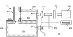
- (Filtration System Z) 3 is a diagram showing a configuration example of the filtration system Z.
- the filtration device 1 is shown in a cross-sectional view taken along the line A2-A2 in FIG.
- an exhaust pump 521 is connected to the first exhaust port 501 and the second exhaust port 502 of the filtration device 1.
- the exhaust pump 521 generates a pressure difference used for filtering the liquid.
- the first exhaust port 501 and the second exhaust port 502 are connected to the exhaust pump 521 via a pipe 513.
- the pipe 513 is provided with a first exhaust valve 511, a second exhaust valve 512, and a pipe filter 531.
- the pipe filter 531 prevents fine particles from flowing from the filtration device 1 into the exhaust pump 521.
- the second liquid holding portion 201 and the third liquid holding portion 301 are connected to the exhaust pump 521.
- the first exhaust valve 511 is provided in the first exhaust port 501, and is capable of switching between an exhaust state and an open-to-atmosphere state of the second liquid holding portion 201.
- the second exhaust valve 512 is provided in the second exhaust port 502, and like the first exhaust valve 511, is capable of switching between an exhaust state and an open-to-atmosphere state of the third liquid holding portion 301. In this way, the first exhaust valve 511 and the second exhaust valve 512 are switchable between the exhaust pump 521 side and the open-to-atmosphere side.
- the exhaust pump 521 is a diaphragm vacuum pump, a dry pump, or the like that can operate at a low vacuum.
- the piping filter 531 is used for the purpose of preventing the suction of fine particles into the exhaust pump 521 and preventing the exhaust pump 521 from breaking down or releasing fine particles from the exhaust port of the exhaust pump 521.
- the piping filter 531 is, for example, an air filter such as a HEPA filter.
- a trap tube (not shown) or the like may be used as necessary to prevent the suction of fine particles into the exhaust pump 521.
- one piping filter 531 is provided, but two may be provided to correspond to each of the first exhaust valve 511 and the second exhaust valve 512.
- the first exhaust valve 511 and the second exhaust valve 512 can be either manual or electric. When the first exhaust valve 511 and the second exhaust valve 512 are electric, the operation can be simplified by linking the operation of the exhaust pump 521 with the control device 600.
- the pipe 513 is made of, for example, metal or rubber. It is preferable to use a pipe 513 having a hardness that does not cause the pipe 313 to be crushed by suction during exhaust and the exhaust is not stagnated. If the first exhaust valve 511 and the second exhaust valve 512 are electric, the first exhaust valve 511 and the second exhaust valve 512 can be controlled by the control device 600.
- the exhaust pump 521 may be controlled manually or by the control device 600.
- the drainage liquid 711 (see FIG. 9) collected in the second liquid holding unit 201 or the third liquid holding unit 301 by filtration can be treated using a purification (sterilization) device (not shown) as necessary.
- FIG. 4 is a diagram showing the disassembled state of the filtration device 1.
- the filtration device 1 is shown in a cross-sectional view taken along the arrows similar to FIG.
- the first member 100 is detachable from the second member 200 and the third member 300.
- the first filter 412 provided in the first hole 411 is detachable. In this manner, the user can easily remove the first filter 412.
- the microparticle suspension 700 is filtered by filtering the microparticles 701 in the microparticle suspension 700 with the first filter 412 and the second filter 422, the user can remove the first filter 412.
- the microscope in this embodiment is an electron microscope, an optical microscope, an atomic force microscope, or the like.
- the exhaust pump 521 sucks and filters the microparticle suspension 700 through the first filter 412 having a large number of fine holes, resulting in a state in which the microparticles 701 are dispersed and captured on the first filter 412.
- the first filter 412 on which the microparticles 701 are dispersed and captured serves as a sample for microscopic observation. In this manner, a sample for microscopic observation can be prepared.
- the second filter 422 is not used for microscopic observation.
- the second member 200 and the third member 300 may be disassembled or may not be disassembled.
- FIG. 5 and 6 are diagrams showing the configuration of the first filter 412.
- the first filter 412 has a filter body 431 and a frame 432 provided on the outer periphery of the filter body 431.
- the frame 432 has a hardness that allows it to be gripped.
- the frame 432a is provided around the filter body 431a having a rectangular shape.
- the frame 432b is provided around the filter body 431b having a circular shape.
- the shapes of the filter body 431 and the frame 432 are not limited to the shapes shown in Fig. 5 and Fig. 6, and may be elliptical or polygonal other than rectangular.
- the filter body 431 which is thin and difficult to handle by itself, is fixed to the frame 432. This makes it easier for the user to grasp the first filter 412. As a result, it becomes easier to attach and detach the first filter 412 to and from the filtration device 1, and to mount the first filter 412 on a sample stage of a microscope (not shown).
- a conductive material for the frame 432 for example, charging due to an electron beam during observation with an electron microscope can be alleviated.
- the filter body 431 may be directly subjected to a conductive treatment, such as coating with gold or platinum. This is also effective in alleviating charging due to an electron beam.
- the filter body 431 is made of, for example, polycarbonate (PC), polyester (PET), polyimide (PI), regenerated cellulose, nitrocellulose, cellulose acetate, mixed cellulose ester, polypropylene, nylon, polyamide, polytetrafluoroethylene (PTFE), polyvinylidene chloride (PVC), polyvinylidene fluoride (PVDF), polyethersulfone (PES), etc.
- PC polycarbonate
- PET polyester
- PI polyimide
- PI regenerated cellulose
- nitrocellulose nitrocellulose
- cellulose acetate mixed cellulose ester
- polypropylene nylon
- polyamide polytetrafluoroethylene
- PVDF polyvinylidene chloride
- PVDF polyvinylidene fluoride
- PES polyethersulfone
- a membrane filter suitable for the filter body 431 is selected from the following viewpoints. (1) Chemical resistance to the reagents used. (2) Whether or not components contained in the sample are adsorbed by the filter material. (3) Is the pore size of filter body 431 small relative to the particulate matter 701 to be collected?
- the material of the filter body 431 of the first filter 412 and the material of the filter body of the second filter 422 may be the same or different.
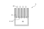
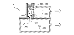
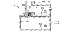
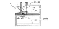
- FIGS. 7 to 9 are diagrams showing an outline of filtration of a particulate suspension 700 using the filtration device 1. In the following figures, only elements of the filtration device 1 that are necessary for explanation are labeled with reference numerals.
- a microparticle suspension 700 containing microparticles 701 is injected into the first liquid holding portion 101.
- the injected microparticle suspension 700 is substantially prevented from flowing into the second liquid holding portion 201 and the third liquid holding portion 301 by the first filter 412 and the second filter 422.
- the first exhaust port 501 and the second exhaust port 502 are connected to an exhaust pump 521 as shown in Fig. 3.
- the first exhaust valve 511 and the second exhaust valve 512 are switched to the connection side (exhaust state) with the exhaust pump 521.
- the second liquid holding portion 201 and the third liquid holding portion 301 are sucked (exhausted) by suction by the exhaust pump 521.
- a solution (wastewater 711) in which the particles 701 have been filtered out of the particle suspension 700 flows into the second liquid holding portion 201 and the third liquid holding portion 301 via the first filter 412 and the second filter 422.
- the particles 701 are filtered in the first filter 412 and the second filter 422.
- the waste liquid 711 is collected in the second liquid holding portion 201 and the third liquid holding portion 301.
- the microparticle suspension 700 injected into the first liquid holding portion 101 is concentrated to the vicinity of the measuring portion 113 provided below the second filter 422. Concentrated to the vicinity of the measuring portion 113 means that the liquid level of the microparticle suspension 700 reaches near the upper end of the measuring portion 113 (the lower end of the second hole 421).
- the microparticle suspension 700 stored in the measuring section 113 is appropriately referred to as a concentrated liquid.
- the microparticle suspension 700 can be concentrated to a certain amount.
- a reagent or the like is added to the concentrated liquid, and the second liquid holding section 201 is further suctioned, and the concentrated liquid stored in the measuring section 113 is collected in the second liquid holding section 201.
- the first filter 412 is then collected. This process will be described later.
- FIG. 10 is a table showing recommended values for the area of the first hole 411.
- the area of the first hole 411 for collecting the microparticles 701 is determined by the number of microparticles 701 in the microparticle suspension 700, the observation area per field of view when observing with a microscope, and the particle density per observation area, as shown in Fig. 10.
- the observation area per field of view with a microscope is determined by the observation magnification of the microscope.
- a filtration device 1 with a diameter of the first hole 411 of ⁇ 2.5 mm is used to suction and filter 50 mL of the microparticle suspension 700 with a concentration of the microparticles 701 of 2000 particles/mL, and observation is performed with a microscope in an observation field of 0.001 mm 2.
- 20 microparticles 701 can be observed per field.
- the area per field of an observation image when observed with a microscope at a magnification of 100 to 10,000 times is 0.0001 to 0.01 mm 2.
- the microparticles 701 are concentrated and collected at a density at which one or more microparticles 701 can be observed per field, so that the microparticles 701 can be observed in any field of view.
- the concentration of the microparticles 701 and the diameter of the first hole 411 (first filter 412) are adjusted so that the density is such that one or more microparticles 701 can be observed in any field of view. In this way, the microparticles 701 can be observed in any field of view, and the time required for observation can be shortened.
- the diameter of the first hole 411 is large, air bubbles may form in part of the first filter 412. If air bubbles form in the first filter 412 in this way, the fine particles 701 may not be collected. In such a case, uniformity in the dispersion of the fine particles 701 in the first filter 412 cannot be maintained. Furthermore, if the diameter of the first hole 411 is small and air bubbles cover the entire bottom surface, suction filtration may not be possible, and the particles may not be collected. Although it depends on conditions such as the concentration of the liquid and the amount of liquid, it is desirable for the diameter of the first hole 411 to be approximately ⁇ 0.5 to 6 mm.
- the filtration device 1 of the first embodiment has a first filter 412 installed in the first hole 411 and a second filter 422 installed in the second hole 421. In this way, filtration is performed using multiple filters, which makes it possible to shorten the filtration time.
- the area of the second hole 421 i.e., the area of the second filter 422
- the filtration device 1 of the first embodiment can efficiently concentrate a large amount of microparticle suspension at a low concentration, and further recover the microparticles in an area suitable for observation.
- the measuring unit 113 by providing the measuring unit 113, it is possible to hold a constant amount of liquid during the process of concentrating the solution (microparticle suspension 700).
- the measuring unit 113 can carry out a process of reacting the microparticles 701 with the additive at a desired (predetermined) concentration.
- the first filter 412 which has a small filtration area, it is possible to collect the microparticles 701 at a density suitable for microscopic observation, and microscopic observation can be easily performed.
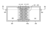
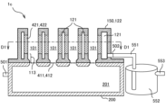
- FIGS. 11 to 14 are schematic diagrams showing an example of the configuration of a filtration device 1a according to the second embodiment.
- Fig. 11 to Fig. 14 an example of the configuration of a multi-well filtration device 1a having a plurality of first holes 411 is shown.
- Fig. 11 is a vertical cross-sectional view (B4-B4 cross-section in Fig. 12) of the filtration device 1a.
- Fig. 12 is a cross-sectional view taken along the line B1-B1 in Fig. 11.
- Fig. 13 is a cross-sectional view taken along the line B2-B2 in Fig. 11.
- Fig. 14 is a cross-sectional view taken along the line B3-B3 in Fig. 11.
- the first member 100a in the filtering device 1a has a configuration in which the first holes 411 are arranged in two parallel rows.
- a first filter 412 is provided in each of the first holes 411.
- four first holes 411 are provided in each row of the first holes 411. Note that, below, the row of the first holes 411 may be simply referred to as a row. In this way, in the filtering device 1a, a plurality of first holes 411 are provided, and a first filter 412 is provided for each of the first holes 411.
- second holes 421 and second filters 422 are provided to correspond to each row of first holes 411.
- third liquid holding portions 301 are provided to correspond to each row of first holes 411. In other words, one second hole 421, one second filter 422, and one third liquid holding portion 301 are provided for each row of first holes 411.
- the first holes 411 are arranged in a row at equal intervals. However, the first holes 411 do not necessarily have to be arranged at equal intervals. Furthermore, the number of first holes 411 is determined by the movable range of the microscope stage, the intervals between the first holes 411, etc.
- a first liquid holding portion 101 is provided for each row.
- a common first liquid holding portion 101 is provided for the first holes 411 that make up the row.
- a common first liquid holding portion 101, second hole 421, and second filter 422 are provided for the multiple first holes 411.
- the filtering device 1a having such a configuration is suitable for filtering one type of microparticle suspension 700 by each of the first filters 412 arranged in one row, in addition to the effects shown in the first embodiment.
- one type of microparticle suspension 700 can be filtered for each row of the first holes 411.
- the measuring sections 113 are formed to correspond to each of the first holes 411.
- the first liquid holding section 101 is connected above the measuring sections 113.
- different reagents 731 can be added to the microparticles 701 filtered by each of the first filters 412.
- the first holes 411 in one row can have the same area (the same diameter).
- the microparticles 701 of the microparticle suspension 700 can be collected in an equal amount in each of the first filters 412 constituting one row in a filtered state.
- the same microparticle suspension 700 may be injected into each of the first liquid holding parts 101 arranged in parallel, or microparticle suspensions 700 in which different microparticles 701 are suspended may be injected.
- the second hole 421 is located above the measuring part 113.
- the second hole 421 and the second filter 422 connected to the first liquid holding part 101 are provided corresponding to the first liquid holding part 101.
- one second hole 421 and one second filter 422 are provided for one first liquid holding part 101. That is, as described above, one second hole 421, one second filter 422, and one third liquid holder 301 are provided for each row of first holes 411.
- the first member 100a is detachable from the second member 200 and the third member 300. Also, a common second liquid holding portion 201 and a common third liquid holding portion 301 are provided for each first liquid holding portion 101.
- the total area of the first filter 412 is less than the area of the second filter 422.
- the first member 100a of the filtration device 1a is divided into members indicated by reference numerals 131, 132a, and 132b.
- the user can individually remove the members indicated by reference numerals 132a and 132b from the second member 200 and the third member 300.
- the first member 100a does not have to be divided as shown in FIG. 11.
- FIGS. 15 to 18 are schematic diagrams showing an example of the configuration of a filtration device 1b according to the third embodiment.
- FIG. 15 to 18 an example of the configuration of a multi-well filtration device 1b having a plurality of first holes 411 is shown.
- FIG. 15 is a schematic diagram showing an example of the configuration of a filtering device 1b according to the third embodiment.
- Fig. 15 is a vertical cross-sectional view of the filtering device 1b
- Fig. 16 is a cross-sectional view taken along line C1-C1 in Fig.
- Fig. 17 is a cross-sectional view taken along line C2-C2 in Fig. 15.
- the filtering device 1b has one row of first holes 411 provided in the first member 100b.
- the rows of the first holes 411 may be arranged in two parallel rows.
- a plurality of first holes 411 (four in the example shown in Figure 16) are provided in one row.
- the filtering device 1b has a plurality of first holes 411, and a first filter 412 is provided for each of the first holes 411.
- a first liquid holding portion 101 is provided for each of the multiple first holes 411. That is, a first liquid holding portion 101 is provided independently for each of the first holes 411 arranged in a row. Also, as shown in FIG. 16, a measuring portion 113 is provided for each of the first liquid holding portions 101. With this configuration, it is possible to inject different types of microparticle suspension 700 into each of the first liquid holding portions 101. That is, one or more types (multiple) of microparticle suspension 700 can be injected into the filtration device 1b. This allows each of the first filters 412 to filter different microparticle suspensions 700. Also, as shown in FIG. 15, the lower end of the second hole 421 is provided at least above the measuring portion 113. Also, as shown in FIG. 17, the second filter 422 connected to the first liquid holding portion 101 can be composed of a single filter.
- a second liquid holding portion 201 and a third liquid holding portion 301 are provided in common for each first liquid holding portion 101.
- FIG. 18 is a diagram showing another example of the filtering device 1b. As shown in FIG. 18, the second filters 422 connected to the first liquid holding parts 101 may be provided so as to correspond to each of the multiple first liquid holding parts 101 provided.
- the total area of the first filter 412 is less than the total area of the second filter 422.
- the total area of the first filter 412 may be equal to or greater than the total area of the second filter 422.
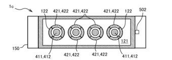
- FIGS. 19 and 20 are schematic diagrams showing an example of the configuration of a filtration device 1c according to the fourth embodiment.
- FIG. 19 and FIG. 20 schematic diagrams showing an example of the configuration of a multi-well filtration device 1c in which a plurality of first holes 411 are provided are shown.
- Fig. 19 shows a vertical cross-sectional view of the filtration device 1c (a cross-sectional view taken along the line D2-D2 in Fig. 20), and
- Fig. 20 shows a horizontal cross-sectional view of the filtration device 1c (a cross-sectional view taken along the line D1-D1 in Fig. 19). Note that in Fig.
- the drainage pipe 551 and the drainage recovery section 552 are omitted.
- the filtration device 1c is composed of a fourth member 150 which is a first container, and a second member 200.
- the fourth member 150 corresponds to the first member 100a and the third member 300 shown in FIGS.
- the housing 122 of the fourth member 150 has a plurality of recesses, forming a plurality of first liquid holding portions 101 (four in the example shown in Figs. 19-20).
- a plurality of first holes 411 (four in the example shown in Figs. 19-20) are provided, and a first filter 412 is provided in each of the first holes 411.
- the second hole 421 is provided in the fourth member 150 (first container) together with the first liquid holding portion 101.
- a first liquid holding portion 101 is provided for each of the plurality of first holes 411.
- a space 121 corresponding to the third liquid holding portion 301 is provided between the first liquid holding portion 101 and the housing 122.
- a second filter 422 is provided on a part of the wall surface constituting the first liquid holding portion 101.
- the second filter 422 is provided in a second hole 421 provided on the side surface of the first liquid holding portion 101.
- a space 121 is provided between the periphery of the second hole 421 and the housing 122 of the fourth member 150, which is the first container.
- the cylindrical second filter 422 is provided so as to surround the first liquid holding portion 101, but this is not limited to this.
- the second filter 422 may be provided only on a part of the periphery of the first liquid holding portion 101.
- the first liquid holding portion 101 is composed of the housing 122 except for the part where the second filter 422 is provided.
- the part from the lower end of the second hole 421 to the bottom surface (bottom) of the first liquid holding portion 101 is provided as the measuring portion 113.
- the housing 122 is provided with a second exhaust port 502.
- the space 121 is connected to the drainage liquid collection unit 552 by the second exhaust port 502 and the drainage pipe 551.
- the exhaust pump 521 (see FIG. 3) is connected to the suction connection part 553 connected to the upper part of the drainage liquid collection unit 552.
- suction is performed by the exhaust pump 521 connected to the suction connection part 553.
- This creates a pressure difference between the space 121 connected to the drainage liquid collection unit 552 and the first liquid holding unit 101. Due to this pressure difference, the drainage liquid 711 (see FIG. 8 and FIG. 9) is discharged to the outside of the first liquid holding unit 101 through the second filter 422.
- the discharged drainage liquid 711 is collected in the drainage liquid collection unit 552 through the drainage pipe 551.
- first liquid holding parts 101 need to have the configuration shown in FIG. 20 or FIG. 21.
- a common first liquid holding part 101 may be provided for multiple first filters 412 (the first liquid holding parts 101 shown in FIG. 19 to FIG. 20 may be connected).
- part of the side surface (wall surface) constituting the first liquid holding portion 101 is configured with a second filter 422.
- the housing 122 ensures that the space 121 outside the first liquid holding portion 101 is airtight. The space 121 is sucked by the exhaust pump 521 connected to the second exhaust port 502, whereby the microparticle suspension 700 is filtered by the second filter 422 provided around the first liquid holding portion 101.
- each of the first liquid holding parts 101 is a first hole 411. As shown in Figures 20 and 21, the first liquid holding parts 101 are arranged at equal intervals. However, the first liquid holding parts 101 do not necessarily have to be arranged at equal intervals. As described above, the housing 122 forms a single highly airtight space 121 on the outside of the first liquid holding parts 101.
- FIG. 22 is a diagram showing a modified example regarding the arrangement of the first liquid holding portion 101.
- the first liquid holding units 101 are arranged at equal intervals in the row and column directions.
- the periphery of the first liquid holding units 101 arranged at equal intervals is covered with a housing 122 as shown in Fig. 20 and Fig. 21, and the space between the housing 122 and each of the first liquid holding units 101 is substantially sealed.
- the second filter 422 is provided in the second hole 421.
- the space 121 provided around the first liquid holding portion 101 corresponds to the third liquid holding portion 301, and there is no need to provide the third liquid holding portion 301 as in the first to third embodiments. Therefore, as shown in FIG. 22, the first holes 411 (i.e., cylindrical containers) can be theoretically arranged without any restrictions.
- the number of first holes 411 is determined by the movable range of the microscope stage and the spacing between the first holes 411.
- FIGS. 23 and 24 are diagrams showing a filtering device 1 according to a fifth embodiment.
- the filtering device 1 according to the fifth embodiment has a liquid delivery nozzle 801 capable of injecting liquid into the first liquid holding portion 101.
- the liquid delivered by the liquid delivery nozzle 801 is a microparticle suspension 700 or the like.
- FIG. 23 shows a filtration device 1 according to the first embodiment equipped with a liquid delivery nozzle 801
- FIG. 24 shows a filtration device 1b according to the third embodiment equipped with a liquid delivery nozzle 801.
- the liquid when the microparticle suspension 700 is delivered to the first liquid holding section 101, the liquid can be discharged from a predetermined position (predetermined height) relative to the first filter 412 at a predetermined speed.
- the predetermined position is a height at which no air bubbles are generated on the surface of the first filter 412.
- air bubbles may cover the entire bottom surface. In such a case, suction filtration cannot be performed, and a state in which the microparticles 701 cannot be collected may occur.
- the liquid delivery nozzle 801 is positioned so as to be adjacent to the first filter 412, and then the microparticle suspension 700 is delivered from the liquid delivery nozzle 801. This allows the microparticle suspension 700 delivered from the liquid delivery nozzle 801 to dissipate the air in the vicinity of the first filter 412. As a result, it is possible to prevent air bubbles from forming on the first filter 412.
- air bubbles may cover the entire bottom surface of the first hole 411, i.e., the entire top surface of the first filter 412. This state may also cause cases in which the exhaust pump 521 is unable to aspirate and filter the microparticle suspension 700.
- the delivery nozzle 801 is brought closer to the first filter 412 than when the microparticle suspension 700 is delivered, and the microparticle suspension 700 is aspirated and discharged at a predetermined speed one or more times. In this way, the air bubbles can be sucked in, eliminated, or released into the microparticle suspension 700 by the delivery nozzle 801. This allows the air bubbles to be removed from the bottom surface of the first hole 411 (i.e., the top surface of the first filter 412).
- the liquid delivery nozzle 801 is placed at a predetermined position on the first filter 412.
- the predetermined position means a position suitable for removing the air bubbles.
- the microparticle suspension 700 is discharged from the liquid delivery nozzle 801 at a predetermined speed.
- the predetermined speed means a speed suitable for removing the air bubbles. Air bubbles may remain in the first hole 411 even after the microparticle suspension 700 is injected into the first liquid holding portion 101.
- the liquid delivery nozzle 801 is placed near the first filter 412, and then the air bubbles can be removed by repeatedly sucking and delivering the liquid by the liquid delivery nozzle 801. If the first hole 411 (i.e., the upper surface of the first filter 412) is filled with the microparticle suspension 700, this process does not need to be performed.
- the first liquid holding portion 101 is not independent of the first hole 411.
- the first liquid holding portion 101 is provided as a common first liquid holding portion 101 for a plurality of first holes 411.
- the microparticle suspension 700 is simultaneously dispensed into the plurality of first holes 411 using a dispenser (not shown) having a plurality of pipettes (multi-pipettes) corresponding to the liquid delivery nozzles 801.
- a dispenser not shown
- the spacing between the first holes 411 may be set to match the spacing of an arbitrarily designed multi-pipette.
- the installation of the liquid delivery nozzle 801 to the first liquid holding portion 101 and the delivery of the microparticle suspension 700 by the liquid delivery nozzle 801 may be performed manually or mechanically.
- FIG. 25 is a diagram showing an example of the configuration of the filtering device 1 according to the sixth embodiment.
- the filtering device 1 shown in FIG. 25 is the filtering device 1 shown in FIG. 1, and has a liquid sending nozzle 801 capable of injecting a liquid into the first liquid holding portion 101.
- the liquid may be the microparticle suspension 700 or a cleaning liquid.
- the microparticles 701 may be captured by the second filter 422. In such a case, a predetermined liquid is sent from the liquid sending nozzle 801 toward the second filter 422.
- the predetermined liquid is the microparticle suspension 700 or a cleaning liquid.
- the microparticles 701 captured by the second filter 422 are washed.
- the microparticles 701 captured by the second filter 422 can be returned to the microparticle suspension 700 injected into the first liquid holding portion 101.
- the technique shown in FIG. 25 is not limited to the filtering device 1 shown in the first embodiment, but can also be applied to the filtering devices 1a to 1c shown in the second to fifth embodiments.
- the first liquid holding portion 101 is not independent of the first hole 411, as in the filtering device 1a shown in the second embodiment (FIGS. 11 to 14)
- the method shown in the sixth embodiment can also be applied to the filtration device 1b shown in the third embodiment (FIGS. 15 to 18) and the filtration device 1c shown in the fourth embodiment (FIGS. 19 to 22).
- the first liquid holding portion 101 is provided independently for each of the first holes 411.
- FIG. 26 is a flow chart showing the procedure of the filtration method according to this embodiment.
- FIGS. 27 to 36 are schematic diagrams for explaining the procedure of the filtration method according to this embodiment.
- the filtration device 1 shown in the first embodiment is used, but the filtration devices 1a to 1c according to the second to fourth embodiments can also concentrate and collect the particulate suspension 700 in a similar procedure.
- the step numbers indicate the step numbers of the flow chart shown in FIG. 26. And, as shown in FIG.
- the filtration device 1 is connected to the exhaust pump 521.
- FIG. 3 will be referred to as appropriate.
- the first exhaust valve 511, the second exhaust valve 512, and the exhaust pump 521 are controlled by the control device 600.
- the microparticle suspension 700 is injected into the first liquid holding portion 101 (S1).
- the liquid delivery nozzle 801 delivers the liquid to the first filter 412 from a predetermined position at a predetermined liquid delivery speed.
- the predetermined position and the predetermined liquid delivery speed are the position and liquid delivery speed of the liquid delivery nozzle 801 that do not generate air bubbles on the surface of the first filter 412.
- the injection is performed in the following procedure.
- the microparticle suspension 700 is injected from the liquid delivery nozzle 801 into the first filter 412 from a height at which air bubbles are not generated on the surface of the first filter 412. This avoids the problem that the air bubbles cover the entire surface of the first filter 412 due to the small diameter of the first hole 411, making it impossible to perform suction filtration and recover the microparticles 701.
- concentration by suction filtration through the first filter 412 and the second filter 422 is started (S2). Specifically, the control device 600 switches the first exhaust valve 511 and the second exhaust valve 512 shown in FIG. 3 so that they are connected to the exhaust pump 521 (see FIG. 3). The control device 600 then performs exhaust using the exhaust pump 521, thereby exhausting the second liquid holding unit 201 and the third liquid holding unit 301 (white arrows in FIG. 28).
- Step S2 is the first process. That is, in step S2, when the microparticle suspension 700 containing the microparticles 701 is injected into the first liquid holding portion 101, the exhaust pump 521 exhausts the second liquid holding portion 201 and the third liquid holding portion 301.
- the microparticle suspension 700 is suction filtered by the first filter 412 and the second filter 422.
- This suction filtration causes the waste liquid 711 to be discharged to the second liquid holding portion 201 and the third liquid holding portion 301.
- the suction filtration by the first filter 412 may be hindered.
- suction and discharge are repeated one or more times with the tip of the liquid delivery nozzle 801 close to the first filter 412. In this way, air bubbles can be removed from the bottom surface of the first hole 411 (on the surface of the first filter 412).
- the control device 600 stops suction of the second liquid holding section 201 (S3). Then, the control device 600 switches the first exhaust valve 511 to the atmosphere opening side. This opens the second liquid holding section 201 to the atmosphere. Then, after the second liquid holding section 201 is opened to the atmosphere, only the exhaust of the third liquid holding section 301 is performed (white arrow in FIG. 29). In other words, after the second liquid holding section 201 is opened to the atmosphere, concentration by suction filtration continues only with the second filter 422 (S4). In other words, the control device 600 continues exhaust of the third liquid holding section 301.
- the upper end of the measuring section 113 and the liquid level of the microparticle suspension 700 can be made to coincide.
- the second liquid holding portion 201 is sucked in the state shown in FIG. 29, there is a risk that the liquid level of the microparticle suspension 700 will be sucked to a position below the upper end of the measuring portion 113.
- the third liquid holding portion 301 is under negative pressure, the solution of the microparticle suspension 700 will not drip into the second liquid holding portion 201.
- the microparticle suspension 700, cleaning liquid, etc. may be sent to the second filter 422 as shown in FIG. 25.
- Step S3 is the second process. That is, in step S3, the liquid level of the microparticle suspension 700 reaches near the lower end of the second hole 421, and the evacuation of the second liquid holding portion 201 is stopped. Then, in step S4, the evacuation of the third liquid holding portion 301 continues.
- the solution in the microparticle suspension 700 may be gradually replaced with a different type of solution.
- the solution to be replaced is sent to the first liquid holding portion 101, and then concentration and discharge are repeated in steps S1 to S3. This makes it possible to replace the solution in the microparticle suspension 700.
- the liquid level of the microparticle suspension 700 is concentrated up to the top of the measuring section 113 (reaching the bottom end of the second hole), and discharge by the third liquid holding section 301 is no longer performed.
- the control device 600 stops suction filtration by the exhaust pump 521 (S5).
- the control device 600 then switches the second exhaust valve 512 to the atmospheric open side. This also opens the third liquid holding section 301 to the atmosphere (S6). In this way, the concentrated solution can be held at the capacity of the measuring section 113.
- the liquid volume of the microparticle suspension 700 (concentrated liquid) can be kept constant.
- Step S5 is the third process. That is, in step S5, the liquid level of the microparticle suspension 700 reaches the lower end of the second hole 421, and the exhaust of the third liquid holding portion 301 is stopped.
- the additive When an additive is added to the microparticle suspension 700, the additive is added to the concentrated microparticle suspension 700 (concentrate) (S7). As a result, as shown in FIG. 31, the microparticle suspension 700 becomes an additive mixture 721, which is a mixture (liquid) of the microparticle suspension 700 and the additive. Since the amount of the concentrate is constant, the concentration of the additive in the concentrate can be adjusted to a desired concentration by the amount of additive added.
- the additive is, for example, an antibacterial agent.
- the antibacterial agent is added to stop the activity of the microorganisms, which are the microparticles 701, in order to check whether the solution of the microparticle suspension 700 is affecting them at a predetermined timing. Note that if it is for a short time, the solution of the additive mixture 721 will not drip into the second liquid holding portion 201. Step S7 allows the reaction between the additive and the microparticle suspension 700 to occur in the filtration device 1.
- the control device 600 switches the first exhaust valve 511 to the exhaust pump 521 side. Then, the control device 600 performs suction using the exhaust pump 521, thereby suctioning the second liquid holding portion 201 (white arrow in FIG. 32: S8). As a result, the additive mixture 721 is discharged into the second liquid holding portion 201. The drained liquid 711 becomes a mixture of the microparticle suspension 700 solution and the additive.
- Step S8 is the fourth process. That is, in step S8, the second liquid holding portion 201 is evacuated. In particular, after step S6, when the additive is added to the microparticle suspension 700 in step S7, the second liquid holding portion 201 is evacuated.
- step S8 as shown in FIG. 33, all of the solution (wastewater 711) of the additive mixture 721 stored in the measuring section 113 is collected via the first filter 412. This causes the fine particles 701 to be collected by the first filter 412, as shown in FIG. 33.
- the control device 600 stops the suction by the exhaust pump 521 (S9).
- the fine particles 701 collected by the first filter 412 may be modified, including fixation and staining, for observation under a microscope.
- the control device 600 stops the suction of the second liquid holding unit 201 as shown in step S9, and switches the first exhaust valve 511 to the atmospheric open side.
- a liquid reagent 731 is added to the first filter 412 (S10).
- the reagent 731 is for modification such as fixation and staining.
- the fine particles 701 and the reagent 731 are reacted for a desired time as necessary.
- liquid may be sent as shown in FIG. 23 or FIG. 24. That is, the tip of the liquid delivery nozzle 801 that delivers the reagent 731 is set so that the distance between the tip and the first filter 412 is a predetermined position, and then the liquid delivery nozzle 801 delivers the reagent 731.
- the predetermined position is a position where the delivered reagent 731 does not form air bubbles on the surface of the first filter 412. That is, when the liquid reagent 731 is injected from the liquid delivery nozzle 801 into the first liquid holding unit 101, the injection is performed in the following procedure. That is, the reagent 731 is injected from the liquid delivery nozzle 801 into the first filter 412 from a height at which no air bubbles are generated on the surface of the first filter 412.
- the control device 600 switches the first exhaust valve 511 to the exhaust pump 521 side, and then performs suction with the exhaust pump 521. This starts suction of the second liquid holding unit 201 (white arrow in FIG. 35: S11).
- the reagent 731 is discharged to the second liquid holding unit 201.
- a cleaning liquid (not shown) is sent to the first liquid holding unit 101, and the suction filtration of step S11 is performed.
- the drainage liquid 711 is a mixture of the microparticle suspension 700 solution, additives, and reagent 731.
- Step S11 is the fifth process. After step S8, a specific reagent 731 is added to the particles 701 present on the surface of the first filter 412, and then step S11 is performed.
- the user removes the first filter 412 from the filtration device 1 in the procedure shown in FIG. 4 (S12). The user then places the removed first filter 412 under a microscope and observes the first filter 412 through the microscope (S13).
- the process of sending the particulate suspension 700, cleaning liquid, etc. to the second filter 422 as shown in Fig. 25 is performed at the timing of step S3, but this is not limited to this.
- the process of sending the particulate suspension 700, cleaning liquid, etc. to the second filter 422 may be performed at the timing when the second filter 422 is exposed.
- the process of sending the particulate suspension 700, cleaning liquid, etc. to the second filter 422 may be performed at any timing of steps S3 (second step) to S13.
- any timing of steps S3 to S8 (fourth step) and even more ideally, any timing before the additive is added (S3 to S6) is preferable.
- the present invention is not limited to the above-described embodiments, and includes various modified examples.
- the above-described embodiments have been described in detail to clearly explain the present invention, and are not necessarily limited to having all of the configurations described. It is also possible to replace part of the configuration of one embodiment with the configuration of another embodiment, and it is also possible to add the configuration of another embodiment to the configuration of one embodiment. It is also possible to add, delete, or replace part of the configuration of each embodiment with other configurations.
- a first liquid holding portion 101 common to multiple first holes 411 may be mixed with a first liquid holding portion 101 corresponding to one of the first holes 411 as in the third embodiment.
- one of the members indicated by reference numerals 132a and 132b in FIG. 11 may be replaced with the first member 100b shown in FIGS. 15 to 18. In this way, it is possible to easily realize a state in which a first liquid holding portion 101 common to multiple first holes 411 and a first liquid holding portion 101 corresponding to one of the first holes 411 are mixed.
- Fig. 37 is a schematic diagram showing another example of the filtering device 1a according to the second embodiment
- Fig. 38 is a diagram showing the configuration of another example of the first filter 412a used in the filtering device 1a according to the second embodiment.
- the first filters 412 may be provided independently so as to correspond to the respective first holes 411, or may be configured as one filter as the first filter 412a shown in Fig. 37. In this manner, the first filters 412 (see Fig. 13) or the first filters 412a (see Fig. 37) are provided for the respective first holes 411.
- the first filter 412a is configured as one filter
- the first filter 412a is provided between the first member 100a and the second member 200 as shown in Fig. 37.
- first member 100a and the second member 200 are separated in Fig. 37, the first member 100a and the second member 200 are in close contact with each other during filtration of the microparticle suspension 700.
- the first filter 412a is fixed by being sandwiched between the first member 100a and the second member 200, which are in close contact with each other.
- the first member 100a and the second member 200 are configured such that the particulate suspension 700 to be filtered does not leak even when the first filter 412a is sandwiched between them.
- the first member 100a and the second member 200 can be separated, allowing the first filter 412a to be easily removed.
- the first filter 412a When the first filter 412a is composed of a single filter as shown in FIG. 37, the first filter 412a has a configuration in which a frame 432a is provided around a rectangular filter body 431a as shown in FIG. 38. In this case, as shown by reference numeral 441 in FIG. 38, the fine particles 701 are collected at a location corresponding to the first hole 411. With the configuration shown in FIG. 37 and FIG. 38, multiple collection results can be observed during microscopic observation by simply setting the first filter 412a once.
- FIG. 39 is a schematic diagram showing another example of the filtering device 1b according to the third embodiment.
- the first filter 412 may be provided independently so as to correspond to each of the first holes 411, or may be configured as one filter as shown in FIG. 39.
- the first filter 412a is configured as one filter, the first filter 412a is provided between the first member 100b and the second member 200 as shown in FIG. 39.
- the first member 100b and the second member 200 are separated in FIG. 39, the first member 100b and the second member 200 are in a state of close contact when filtering the microparticle suspension 700.
- the first filter 412a is fixed by being sandwiched between the first member 100b and the second member 200, which are in close contact with each other.
- the first member 100b and the second member 200 are configured such that the microparticle suspension 700 to be filtered does not leak even when the first filter 412a is sandwiched between them.
- the first member 100b and the second member 200 can be separated, allowing the first filter 412a to be easily removed.
- the configuration of the first filter 412a and the collection location of the fine particles 701 will be the same as that shown in FIG. 38.
- control device 600 etc. described above may be realized in part or in whole in hardware, for example by designing it as an integrated circuit.
- the configuration, functions, etc. of the control device 600 may also be realized in software by a processor such as a CPU interpreting and executing programs that realize each function.
- Information such as programs, tables, files, etc. that realize each function of the control device 600 can be stored in a memory, a recording device such as an SSD (Solid State Drive), or a recording medium such as an IC (Integrated Circuit) card, SD (Secure Digital) card, or DVD (Digital Versatile Disc), in addition to being stored in an HD (Hard Disk).
- SSD Solid State Drive
- a recording medium such as an IC (Integrated Circuit) card, SD (Secure Digital) card, or DVD (Digital Versatile Disc), in addition to being stored in an HD (Hard Disk).
- control lines and information lines shown are those that are considered necessary for the explanation, and not all control lines and information lines in the product are necessarily shown. In reality, it can be considered that almost all components are interconnected.
Landscapes
- Life Sciences & Earth Sciences (AREA)
- Hydrology & Water Resources (AREA)
- Physics & Mathematics (AREA)
- Health & Medical Sciences (AREA)
- Chemical & Material Sciences (AREA)
- Analytical Chemistry (AREA)
- Biochemistry (AREA)
- General Health & Medical Sciences (AREA)
- General Physics & Mathematics (AREA)
- Immunology (AREA)
- Pathology (AREA)
- Sampling And Sample Adjustment (AREA)
Priority Applications (2)
| Application Number | Priority Date | Filing Date | Title |
|---|---|---|---|
| CN202480011890.8A CN120677368A (zh) | 2023-08-08 | 2024-07-26 | 过滤装置、过滤系统及过滤方法 |
| JP2025539293A JPWO2025033222A1 (https=) | 2023-08-08 | 2024-07-26 |
Applications Claiming Priority (2)
| Application Number | Priority Date | Filing Date | Title |
|---|---|---|---|
| JP2023-129227 | 2023-08-08 | ||
| JP2023129227 | 2023-08-08 |
Publications (1)
| Publication Number | Publication Date |
|---|---|
| WO2025033222A1 true WO2025033222A1 (ja) | 2025-02-13 |
Family
ID=94534139
Family Applications (1)
| Application Number | Title | Priority Date | Filing Date |
|---|---|---|---|
| PCT/JP2024/026864 Pending WO2025033222A1 (ja) | 2023-08-08 | 2024-07-26 | ろ過装置、ろ過システム、及び、ろ過方法 |
Country Status (3)
| Country | Link |
|---|---|
| JP (1) | JPWO2025033222A1 (https=) |
| CN (1) | CN120677368A (https=) |
| WO (1) | WO2025033222A1 (https=) |
Citations (3)
| Publication number | Priority date | Publication date | Assignee | Title |
|---|---|---|---|---|
| JP2014522302A (ja) * | 2011-05-20 | 2014-09-04 | サイマー リミテッド ライアビリティ カンパニー | 材料供給装置のためのフィルタ |
| JP2019514017A (ja) * | 2016-04-28 | 2019-05-30 | ヒューレット−パッカード デベロップメント カンパニー エル.ピー.Hewlett‐Packard Development Company, L.P. | マイクロ流体濾過 |
| WO2021049163A1 (ja) * | 2019-09-09 | 2021-03-18 | 株式会社村田製作所 | 濃縮装置及び濃縮方法 |
-
2024
- 2024-07-26 CN CN202480011890.8A patent/CN120677368A/zh active Pending
- 2024-07-26 WO PCT/JP2024/026864 patent/WO2025033222A1/ja active Pending
- 2024-07-26 JP JP2025539293A patent/JPWO2025033222A1/ja active Pending
Patent Citations (3)
| Publication number | Priority date | Publication date | Assignee | Title |
|---|---|---|---|---|
| JP2014522302A (ja) * | 2011-05-20 | 2014-09-04 | サイマー リミテッド ライアビリティ カンパニー | 材料供給装置のためのフィルタ |
| JP2019514017A (ja) * | 2016-04-28 | 2019-05-30 | ヒューレット−パッカード デベロップメント カンパニー エル.ピー.Hewlett‐Packard Development Company, L.P. | マイクロ流体濾過 |
| WO2021049163A1 (ja) * | 2019-09-09 | 2021-03-18 | 株式会社村田製作所 | 濃縮装置及び濃縮方法 |
Also Published As
| Publication number | Publication date |
|---|---|
| CN120677368A (zh) | 2025-09-19 |
| JPWO2025033222A1 (https=) | 2025-02-13 |
Similar Documents
| Publication | Publication Date | Title |
|---|---|---|
| JP4074058B2 (ja) | 流体試料と粒子物質を混合および流体試料から粒子物質を分離をする方法、およびその装置 | |
| CN105980028B (zh) | 具有滑动阀的过滤装置以及使用该过滤装置的方法 | |
| CN108025238B (zh) | 过滤滤除器、过滤装置以及使用过滤滤除器的过滤方法 | |
| CN103298546B (zh) | 用于细胞过滤的方法和系统 | |
| JP4092085B2 (ja) | 濾過メンブレン用下排液 | |
| WO2011019032A1 (ja) | 試料処理システム | |
| JPWO2014007074A1 (ja) | 磁力体カバー及び核酸抽出装置 | |
| CN110446779A (zh) | 核酸分离装置 | |
| CN115060571A (zh) | 具有一次性流体路径的液体到液体生物粒子浓缩器 | |
| JP2003339374A (ja) | 核酸分離カラム、装置及び核酸抽出方法 | |
| JP6645605B2 (ja) | 濾過装置及び濾過方法 | |
| JPWO2017154349A1 (ja) | 核酸抽出装置、核酸抽出ユニット及び核酸抽出方法 | |
| JP2009118780A (ja) | 微生物検出方法およびろ過装置 | |
| WO2025033222A1 (ja) | ろ過装置、ろ過システム、及び、ろ過方法 | |
| US6149871A (en) | System for processing multiple specimens of biological fluid | |
| JP2010151551A (ja) | 試料前処理装置 | |
| JP5103003B2 (ja) | 細胞処理装置 | |
| JP2007319019A (ja) | 細胞処理方法及び細胞処理装置 | |
| JP6669230B2 (ja) | 濾過装置及び濾過方法 | |
| JP6439902B2 (ja) | サンプリングフィルター、サンプリング装置およびそれを用いたサンプリング方法 | |
| JP2019030286A (ja) | 粒子保持モジュール及び当該モジュールを備えた粒子保持装置 | |
| CN117054204A (zh) | 一种基于膜技术的细胞染色洗涤装置及方法 | |
| HK40081265A (en) | Liquid to liquid biological particle concentrator with disposable fluid path | |
| JP2018171028A (ja) | 核酸分離装置 | |
| KR101729757B1 (ko) | 피펫을 구비한 세포 분리장치 |
Legal Events
| Date | Code | Title | Description |
|---|---|---|---|
| 121 | Ep: the epo has been informed by wipo that ep was designated in this application |
Ref document number: 24851647 Country of ref document: EP Kind code of ref document: A1 |
|
| ENP | Entry into the national phase |
Ref document number: 2025539293 Country of ref document: JP Kind code of ref document: A |
|
| WWE | Wipo information: entry into national phase |
Ref document number: 2025539293 Country of ref document: JP |
|
| WWE | Wipo information: entry into national phase |
Ref document number: 202480011890.8 Country of ref document: CN |
|
| WWP | Wipo information: published in national office |
Ref document number: 202480011890.8 Country of ref document: CN |
|
| NENP | Non-entry into the national phase |
Ref country code: DE |