WO2025028615A1 - 半導体装置 - Google Patents
半導体装置 Download PDFInfo
- Publication number
- WO2025028615A1 WO2025028615A1 PCT/JP2024/027555 JP2024027555W WO2025028615A1 WO 2025028615 A1 WO2025028615 A1 WO 2025028615A1 JP 2024027555 W JP2024027555 W JP 2024027555W WO 2025028615 A1 WO2025028615 A1 WO 2025028615A1
- Authority
- WO
- WIPO (PCT)
- Prior art keywords
- region
- regions
- less
- main surface
- high concentration
- Prior art date
- Legal status (The legal status is an assumption and is not a legal conclusion. Google has not performed a legal analysis and makes no representation as to the accuracy of the status listed.)
- Pending
Links
Images


























Definitions
- the present disclosure provides a semiconductor device having a novel layout.
- the present disclosure provides a semiconductor device including a chip having a main surface, a semiconductor region of a first conductivity type formed in a surface layer portion of the main surface, a termination region of a second conductivity type formed in the surface layer portion of the semiconductor region at the periphery of the main surface, and a high-concentration region of the first conductivity type formed in the surface layer portion of the main surface so as to be positioned in a thickness range between the main surface and a bottom of the termination region, the high-concentration region having an impurity concentration higher than the impurity concentration of the semiconductor region.
- the present disclosure provides a semiconductor device including a chip having a main surface, a semiconductor region of a first conductivity type formed in a surface layer portion of the main surface, a field region of a second conductivity type formed in the surface layer portion of the semiconductor region at the periphery of the main surface, and a high-concentration field region of the second conductivity type formed in the surface layer portion of the main surface so as to be positioned in a thickness range between the main surface and a bottom of the field region, the high-concentration field region having an impurity concentration higher than the impurity concentration of the field region.
- the present disclosure provides a semiconductor device including a chip having a main surface, a semiconductor region of a first conductivity type formed on a surface layer of the main surface, and a termination region of a second conductivity type formed on the surface layer of the semiconductor region at a periphery of the main surface and spaced apart from the main surface in the thickness direction of the chip.
- the present disclosure provides a semiconductor device including a chip having a main surface, a semiconductor region of a first conductivity type formed in a surface layer of the main surface, and a field region of a second conductivity type formed in the surface layer of the semiconductor region at a periphery of the main surface and spaced apart from the main surface in the thickness direction of the chip.
- the present disclosure provides a semiconductor device including a chip having a main surface, a semiconductor region of a first conductivity type formed in a surface layer portion of the main surface, a trench formed in an inner portion of the main surface so as to be positioned within the semiconductor region, and a termination region of a second conductivity type formed in the surface layer portion of the semiconductor region at the periphery of the main surface and having a bottom located closer to the main surface than the depth position of the bottom wall of the trench.
- the present disclosure provides a semiconductor device including a chip having a main surface, a semiconductor region of a first conductivity type formed in a surface layer portion of the main surface, a trench formed in an inner portion of the main surface so as to be positioned within the semiconductor region, and a field region of a second conductivity type formed in the surface layer portion of the semiconductor region at the periphery of the main surface and having a bottom located closer to the main surface than the depth position of the bottom wall of the trench.
- the present disclosure provides a semiconductor device including a chip having a main surface, a semiconductor region of a first conductivity type formed in a surface layer portion of the main surface, a trench structure formed in an inner portion of the main surface so as to be positioned within the semiconductor region, a well region of a second conductivity type formed in a surface layer portion of the semiconductor region so as to be positioned on the peripheral side of the main surface relative to the trench structure, and the termination region of the second conductivity type formed in the surface layer portion of the semiconductor region so as to be positioned on the peripheral side of the main surface relative to the well region.
- the present disclosure provides a semiconductor device including a chip having a first surface portion and a second surface portion recessed in the thickness direction relative to the first surface portion, a semiconductor region of a first conductivity type formed in a surface layer portion of the second surface portion, and a termination region of a second conductivity type formed in the surface layer portion of the semiconductor region spaced apart from the second surface portion in the thickness direction of the chip.
- the present disclosure provides a semiconductor device including a chip having a first surface portion and a second surface portion recessed in the thickness direction relative to the first surface portion, a semiconductor region of a first conductivity type formed in a surface layer portion of the second surface portion, and a field region of a second conductivity type formed in the surface layer portion of the semiconductor region in the second surface portion and spaced from the second surface portion in the thickness direction of the chip.
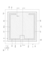
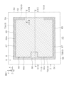
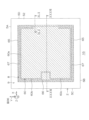
- FIG. 1 is a plan view showing a semiconductor device according to a first embodiment.
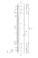
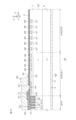
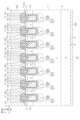
- FIG. 2 is a cross-sectional view taken along the line II-II shown in FIG.
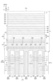
- FIG. 3 is a plan view showing an example of the layout of the first main surface.
- FIG. 4 is an enlarged plan view showing a main portion of the first main surface shown in FIG.
- FIG. 5 is an enlarged plan view showing a main portion of the first main surface shown in FIG.
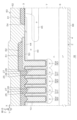
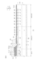
- FIG. 6 is a cross-sectional view taken along the line VI-VI shown in FIG.
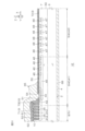
- FIG. 7 is a cross-sectional view taken along line VII-VII shown in FIG.
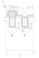
- FIG. 8 is an enlarged cross-sectional view of the area shown in FIG. FIG.
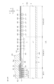
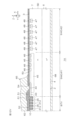
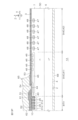
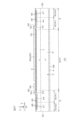
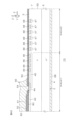
- FIG. 10A is a cross-sectional view showing a cross-sectional structure of the outer periphery region taken along line X-X shown in FIG. 1 together with the outer periphery structure according to the first embodiment.
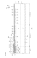
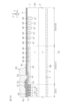
- FIG. 10B is a cross-sectional view showing the cross-sectional structure of the outer periphery region taken along line X-X shown in FIG. 1 together with the outer periphery structure according to the second embodiment.
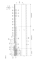
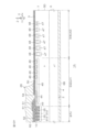
- FIG. 10C is a cross-sectional view showing a cross-sectional structure of the outer periphery region taken along line X-X shown in FIG. 1 together with the outer periphery structure according to the third embodiment.
- FIG. 10A is a cross-sectional view showing a cross-sectional structure of the outer periphery region taken along line X-X shown in FIG. 1 together with the outer periphery structure according to the first embodiment.
- FIG. 10B is a cross-sectional view showing the cross-sectional structure of the outer periphery region
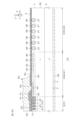
- FIG. 10D is a cross-sectional view showing the cross-sectional structure of the outer periphery region taken along line X-X shown in FIG. 1 together with the outer periphery structure according to the fourth embodiment.
- FIG. 10E is a cross-sectional view showing the cross-sectional structure of the outer periphery region taken along line X-X shown in FIG. 1 together with the outer periphery structure according to the fifth embodiment.
- FIG. 10F is a cross-sectional view showing the cross-sectional structure of the outer periphery region taken along line X-X shown in FIG. 1 together with the outer periphery structure according to the sixth embodiment.
- FIG. 11 is a simulation graph showing the breakdown voltage when the peripheral structures according to the first to sixth embodiments are adopted.
- FIG. 12A is a cross-sectional view showing a first outer periphery structure according to a first modified example.
- FIG. 12B is a cross-sectional view showing a first outer periphery structure according to a second modified example.
- FIG. 12C is a cross-sectional view showing a first outer periphery structure according to a third modified example.
- FIG. 12D is a cross-sectional view showing a first outer periphery structure according to a fourth modified example.
- FIG. 12E is a cross-sectional view showing a first outer periphery structure according to the fifth modified example.
- FIG. 12F is a cross-sectional view showing a first outer periphery structure according to a sixth modified example.
- FIG. 12A is a cross-sectional view showing a first outer periphery structure according to a first modified example.
- FIG. 12B is a cross-sectional view showing a first outer periphery structure according to a second modified example.
- FIG. 12G is a cross-sectional view showing a first outer periphery structure according to the seventh modified example.
- FIG. 12H is a cross-sectional view showing a first outer periphery structure according to an eighth modified example.
- FIG. 12I is a cross-sectional view showing a first outer periphery structure according to a ninth modified example.
- FIG. 12J is a cross-sectional view showing a first outer periphery structure according to a tenth modified example.
- FIG. 12K is a cross-sectional view showing a first outer periphery structure according to an eleventh modified example.
- FIG. 12L is a cross-sectional view showing a first outer periphery structure according to a twelfth modified example.
- FIG. 12G is a cross-sectional view showing a first outer periphery structure according to the seventh modified example.
- FIG. 12H is a cross-sectional view showing a first outer periphery structure according to an eighth modified
- FIG. 12M is a cross-sectional view showing a first outer periphery structure according to a thirteenth modified example.
- FIG. 12N is a cross-sectional view showing a first outer periphery structure according to a fourteenth modified example.
- FIG. 12O is a cross-sectional view showing a first outer periphery structure according to a fifteenth modification.
- FIG. 12P is a cross-sectional view showing a first outer periphery structure according to a sixteenth modified example.
- FIG. 12Q is a cross-sectional view showing a first outer periphery structure according to a seventeenth modified example.
- FIG. 12R is a cross-sectional view showing a first outer periphery structure according to an eighteenth modified example.
- FIG. 12M is a cross-sectional view showing a first outer periphery structure according to a thirteenth modified example.
- FIG. 12N is a cross-sectional view showing a first outer periphery structure according
- FIG. 12S is a cross-sectional view showing a first outer periphery structure according to a nineteenth modification.
- FIG. 12T is a cross-sectional view showing a first outer periphery structure according to a twentieth modification example.
- FIG. 12U is a cross-sectional view showing a first outer periphery structure according to a twenty-first modified example.
- FIG. 12V is a cross-sectional view showing a first outer periphery structure according to a twenty-second modified example.
- FIG. 13A is a cross-sectional view showing a second outer periphery structure according to a first modified example.
- FIG. 13B is a cross-sectional view showing a second outer periphery structure according to the second modified example.
- FIG. 13A is a cross-sectional view showing a second outer periphery structure according to a first modified example.
- FIG. 13B is a cross-sectional view showing a second outer periphery structure according to the second modified example
- FIG. 13C is a cross-sectional view showing a second outer periphery structure according to a third modified example.
- FIG. 13D is a cross-sectional view showing a second outer periphery structure according to the fourth modified example.
- FIG. 13E is a cross-sectional view showing a second outer periphery structure according to the fifth modified example.
- FIG. 13F is a cross-sectional view showing a second outer periphery structure according to the sixth modified example.
- FIG. 13G is a cross-sectional view showing a second outer periphery structure according to the seventh modified example.
- FIG. 13H is a cross-sectional view showing a second outer periphery structure according to the eighth modified example.
- FIG. 13C is a cross-sectional view showing a second outer periphery structure according to a third modified example.
- FIG. 13D is a cross-sectional view showing a second outer periphery structure according to the fourth modified example.
- FIG. 13E
- FIG. 13I is a cross-sectional view showing a second outer periphery structure according to a ninth modified example.
- FIG. 13J is a cross-sectional view showing a second outer periphery structure according to a tenth modified example.
- FIG. 13K is a cross-sectional view showing a second outer periphery structure according to an eleventh modified example.
- FIG. 13L is a cross-sectional view showing a second outer periphery structure according to a twelfth modified example.
- FIG. 13M is a cross-sectional view showing a second outer periphery structure according to the thirteenth modified example.
- FIG. 13N is a cross-sectional view showing a second outer periphery structure according to a fourteenth modification.
- FIG. 13I is a cross-sectional view showing a second outer periphery structure according to a ninth modified example.
- FIG. 13J is a cross-sectional view showing a second outer periphery structure according to
- FIG. 13O is a cross-sectional view showing a second outer periphery structure according to a fifteenth modification.
- FIG. 13P is a cross-sectional view showing a second outer periphery structure according to a sixteenth modified example.
- FIG. 13Q is a cross-sectional view showing a second outer periphery structure according to the seventeenth modified example.
- FIG. 13R is a cross-sectional view showing a second outer periphery structure according to an eighteenth modified example.
- FIG. 13S is a cross-sectional view showing a second outer periphery structure according to the nineteenth modification.
- FIG. 13T is a cross-sectional view showing a second outer periphery structure according to a twentieth modified example.
- FIG. 13O is a cross-sectional view showing a second outer periphery structure according to a fifteenth modification.
- FIG. 13P is a cross-sectional view showing a second outer periphery structure according to a sixteenth modified
- FIG. 13U is a cross-sectional view showing a second outer periphery structure according to a twenty-first modified example.
- FIG. 13V is a cross-sectional view showing a second outer periphery structure according to a twenty-second modified example.
- FIG. 13W is a cross-sectional view showing a second outer periphery structure according to the twenty-third modified example.
- FIG. 13X is a cross-sectional view showing a second outer periphery structure according to a twenty-fourth modified example.
- FIG. 13Y is a cross-sectional view showing a second outer periphery structure according to the twenty-fifth modified example.
- FIG. 13Z is a cross-sectional view showing a second outer periphery structure according to a twenty-sixth modified example.
- FIG. 14 is a cross-sectional view showing a main part of an active region of a semiconductor device according to the second embodiment.
- 15 is a cross-sectional view showing a main part of the active region of the semiconductor device shown in FIG.
- FIG. 16 is a cross-sectional view showing the peripheral region of the semiconductor device shown in FIG. 14 together with the peripheral structure according to the first embodiment.
- FIG. 17 is an enlarged plan view showing a main portion of an active region of a semiconductor device according to the third embodiment.
- 18 is a cross-sectional view taken along line XVIII-XVIII shown in FIG. 17.
- FIG. 19 is a cross-sectional view taken along line XIX-XIX shown in FIG. 20 is a cross-sectional view showing a main part of the active region of the semiconductor device shown in FIG.
- FIG. 21 is a plan view showing a semiconductor device according to the fourth embodiment. 22 is a cross-sectional view taken along line XXII-XXII shown in FIG. 21.
- FIG. 23 is a perspective view showing the shape of the chip.
- FIG. 24 is a plan view showing an example of the layout of the first main surface. 25 is an enlarged plan view showing a main portion of the first main surface shown in FIG. 24.
- FIG. 26 is an enlarged plan view showing a main portion of the first main surface shown in FIG. 24.
- FIG. 27 is a cross-sectional view taken along line XXVII-XXVII shown in FIG. 26.
- FIG. FIG. 28 is a cross-sectional view showing a cross-sectional structure of the outer periphery region taken along the line XXVIII-XXVIII shown in FIG. 21 together with the outer periphery structure according to the first embodiment.
- FIG. 29 is a cross-sectional view showing a main part of an active region of a semiconductor device according to the fifth embodiment.
- 30 is a cross-sectional view showing a main part of the active region of the semiconductor device shown in FIG.
- FIG. 31 is a cross-sectional view showing the peripheral region of the semiconductor device shown in FIG. 29 together with the peripheral structure according to the first embodiment.
- FIG. 32 is an enlarged plan view showing an active region of a semiconductor device according to the sixth embodiment.
- 33 is a cross-sectional view taken along line XXXIII-XXXIII shown in FIG. 32.
- FIG. 34 is a cross-sectional view taken along line XXXIV-XXXIV shown in FIG. 32.
- FIG. 35 is a cross-sectional view showing a main part of the active region of the semiconductor device shown in FIG.
- FIG. 36 is a plan view showing a semiconductor device according to the seventh embodiment.
- 37 is a cross-sectional view taken along line XXXVII-XXXVII shown in FIG. 36.
- FIG. FIG. 38 is a plan view showing an example of the layout of the first main surface.
- FIG. 39 is an enlarged plan view showing a main portion of the first main surface shown in FIG. 38.
- FIG. 40 is a cross-sectional view taken along the line XL-XL shown in FIG. 41 is an enlarged cross-sectional view of the area shown in FIG.
- FIG. 42 is a cross-sectional view showing a cross-sectional structure taken along the line XLII-XLII shown in FIG. 39 together with the peripheral structure according to the first embodiment.
- this term includes a numerical value (shape) that is equal to the numerical value (shape) of the comparison target, as well as a numerical error (shape error) within a range of ⁇ 10% based on the numerical value (shape) of the comparison target.
- shape a numerical value that is equal to the numerical value (shape) of the comparison target
- error a numerical error within a range of ⁇ 10% based on the numerical value (shape) of the comparison target.
- the conductivity type of a semiconductor is indicated using “p-type” or “n-type”, but “p-type” may also be referred to as the “first conductivity type” and “n-type” as the “second conductivity type”. Of course, “n-type” may also be referred to as the “first conductivity type” and “p-type” as the “second conductivity type”.
- P-type is a conductivity type resulting from a trivalent element
- n-type is a conductivity type resulting from a pentavalent element.
- Trivalent elements are at least one of boron, aluminum, gallium, and indium.
- Pentavalent elements are at least one of nitrogen, phosphorus, arsenic, antimony, and bismuth.
- FIG. 1 is a plan view showing a semiconductor device 1A according to a first embodiment.
- FIG. 2 is a cross-sectional view taken along line II-II shown in FIG. 1.
- FIG. 3 is a plan view showing an example of the layout of the first main surface 3.
- FIG. 4 is an enlarged plan view showing a main portion of the first main surface 3 shown in FIG. 3.
- FIG. 5 is an enlarged plan view showing a main portion of the first main surface 3 shown in FIG. 3.
- FIG. 6 is a cross-sectional view taken along line VI-VI shown in FIG. 4.
- FIG. 7 is a cross-sectional view taken along line VII-VII shown in FIG. 4.
- FIG. 8 is an enlarged cross-sectional view of an area shown in FIG. 6.
- FIG. 9 is a cross-sectional view taken along line IX-IX shown in FIG. 5.
- semiconductor device 1A is a semiconductor switching device having an insulated gate type transistor structure Tr as an example of a device structure.
- the transistor structure Tr has a trench gate type vertical structure.
- Semiconductor device 1A includes chip 2 formed in a hexahedral shape (specifically, a rectangular parallelepiped shape).
- chip 2 includes a single crystal of a wide bandgap semiconductor.
- semiconductor device 1A is a "wide bandgap semiconductor device.”
- Chip 2 may also be referred to as a “semiconductor chip,” a “wide bandgap semiconductor chip,” etc.
- a wide bandgap semiconductor is a semiconductor that has a bandgap that exceeds the bandgap of Si (silicon).
- Examples of wide bandgap semiconductors include GaN (gallium nitride), SiC (silicon carbide), and C (diamond).
- chip 2 is a "SiC chip” that includes a hexagonal SiC single crystal as an example of a wide bandgap semiconductor.
- semiconductor device 1A is a "SiC semiconductor device.”
- Hexagonal SiC single crystal has multiple polytypes including 2H (Hexagonal)-SiC single crystal, 4H-SiC single crystal, 6H-SiC single crystal, etc.
- the chip 2 includes a 4H-SiC single crystal, but the chip 2 may include other polytypes.
- the chip 2 has a first main surface 3 on one side, a second main surface 4 on the other side, and first to fourth side surfaces 5A to 5D connected to the first main surface 3 and the second main surface 4.
- the first main surface 3 and the second main surface 4 are formed in a quadrangular shape when viewed in a plan view from the vertical direction Z (hereinafter simply referred to as "plan view").
- the vertical direction Z is also the thickness direction of the chip 2.
- the first main surface 3 and the second main surface 4 are preferably formed by the c-plane of the SiC single crystal.
- the first main surface 3 is formed by the silicon surface ((0001) surface) of the SiC single crystal
- the second main surface 4 is formed by the carbon surface ((000-1) surface) of the SiC single crystal.
- the first side surface 5A and the second side surface 5B extend in a first direction X along the first main surface 3 and face a second direction Y that intersects with the first direction X along the first main surface 3. Specifically, the second direction Y is perpendicular to the first direction X.
- the third side surface 5C and the fourth side surface 5D extend in the second direction Y and face the first direction X.
- the first direction X is the m-axis direction ([1-100] direction) of the SiC single crystal
- the second direction Y is the a-axis direction ([11-20] direction) of the SiC single crystal.
- the first direction X may be the a-axis direction of the SiC single crystal
- the second direction Y may be the m-axis direction of the SiC single crystal.
- the horizontal direction is also the XY plane (horizontal plane) formed by the first direction X and the second direction Y, and is perpendicular to the vertical direction Z.
- the chip 2 (first main surface 3 and second main surface 4) has an off angle that is inclined at a predetermined angle in a predetermined off direction relative to the c-plane of the SiC single crystal.
- the c-axis ((0001) axis) of the SiC single crystal is inclined by the off angle from a vertical line along the vertical direction Z toward the off direction.
- the c-plane of the SiC single crystal is inclined by the off angle relative to the horizontal plane.
- the off-direction is preferably the a-axis direction of the SiC single crystal (the second direction Y in this embodiment).
- the off-angle may be greater than 0° and less than or equal to 10°.
- the off-angle may have a value that falls within at least one of the following ranges: greater than 0° and less than or equal to 1°, 1° or more and less than or equal to 2.5°, 2.5° or more and less than or equal to 5°, 5° or more and less than or equal to 7.5°, and 7.5° or more and less than or equal to 10°.
- the off angle is preferably 5° or less. It is particularly preferable that the off angle be 2° or more and 4.5° or less.
- the off angle is typically set in the range of 4° ⁇ 0.1°. This specification does not exclude a configuration in which the off angle is 0° (i.e., a configuration in which the first main surface 3 is a just plane relative to the c-plane).
- the semiconductor device 1A includes an n-type first semiconductor region 6 formed in a surface layer portion of the second main surface 4.
- a drain potential is applied to the first semiconductor region 6 as a first potential (high potential).
- the first semiconductor region 6 may also be referred to as a "base region (layer)", “semiconductor region (layer)”, “drain region (layer)”, etc.
- the first semiconductor region 6 extends in a layered manner along the second main surface 4 and is exposed from the second main surface 4 and the first to fourth side surfaces 5A to 5D.
- the first semiconductor region 6 is made of an n-type semiconductor layer.
- the first semiconductor region 6 is made of a substrate (SiC substrate) containing SiC single crystal (semiconductor single crystal), and forms the second main surface 4 and the first to fourth side surfaces 5A to 5D.
- the first semiconductor region 6 (substrate) has the off direction and off angle described above.
- the first semiconductor region 6 may have a thickness of 10 ⁇ m or more and 500 ⁇ m or less.
- the thickness of the first semiconductor region 6 may have a value that belongs to at least one of the following ranges: 10 ⁇ m or more and 50 ⁇ m or less, 50 ⁇ m or more and 100 ⁇ m or less, 100 ⁇ m or more and 150 ⁇ m or less, 150 ⁇ m or more and 200 ⁇ m or less, 200 ⁇ m or more and 300 ⁇ m or less, 300 ⁇ m or more and 400 ⁇ m or less, and 400 ⁇ m or more and 500 ⁇ m or less.
- the semiconductor device 1A includes an n-type second semiconductor region 7 formed in a surface layer portion of the first main surface 3.
- the second semiconductor region 7 may be referred to as a "semiconductor region (layer)", a “drift region (layer)”, etc.
- the second semiconductor region 7 has an n-type impurity concentration less than the n-type impurity concentration of the first semiconductor region 6.
- the second semiconductor region 7 is formed in a region on the first main surface 3 side with respect to the first semiconductor region 6 in a cross-sectional view, and is electrically connected to the first semiconductor region 6.
- the second semiconductor region 7 extends in a layer shape along the first main surface 3 and is exposed from the first main surface 3 and the first to fourth side surfaces 5A to 5D.
- the second semiconductor region 7 is made of an n-type semiconductor layer.
- the second semiconductor region 7 is made of an epitaxial layer (SiC epitaxial layer) that includes a SiC single crystal (semiconductor single crystal), and forms the first main surface 3 and the first to fourth side surfaces 5A to 5D.
- the second semiconductor region 7 (epitaxial layer) has the off direction and off angle described above. It is preferable that the second semiconductor region 7 has a thickness less than that of the first semiconductor region 6. Of course, the thickness of the second semiconductor region 7 may be greater than the thickness of the first semiconductor region 6.
- the thickness of the second semiconductor region 7 may be 5 ⁇ m or more and 15 ⁇ m or less.
- the thickness of the second semiconductor region 7 may have a value that falls within at least one of the following ranges: 5 ⁇ m or more and 7.5 ⁇ m or less, 7.5 ⁇ m or more and 10 ⁇ m or less, 10 ⁇ m or more and 12.5 ⁇ m or less, and 12.5 ⁇ m or more and 15 ⁇ m or less.
- the semiconductor device 1A includes an active region 8 set in the chip 2.
- the active region 8 includes a device structure (transistor structure Tr) and is a region where an output current (drain current) is generated.
- the active region 8 is set in the inner part of the chip 2 and spaced from the periphery of the first main surface 3 (first to fourth side surfaces 5A to 5D).
- the active region 8 is set to a polygonal shape (a square shape in this embodiment) having four sides parallel to the periphery of the chip 2 in a plan view.
- the ratio (area ratio) of the planar area of the active region 8 to the planar area of the first main surface 3 may be 0.5 or more and 0.95 or less.
- the area ratio may be 0.5 or more and 0.6 or less, 0.6 or more and 0.7 or less, 0.7 or more and 0.8 or less, 0.8 or more and 0.9 or less, or 0.9 or more and 0.95 or less.
- the semiconductor device 1A includes a peripheral region 9 that is set outside the active region 8 in the chip 2.
- the peripheral region 9 is a region that does not include a device structure (transistor structure Tr).
- the peripheral region 9 is set on the periphery of the chip 2.
- the peripheral region 9 is provided in the region between the periphery of the chip 2 and the active region 8 in a plan view.
- the peripheral region 9 extends in a band shape along the active region 8 in a plan view, and is set in a polygonal ring shape (a square ring in this embodiment) surrounding the active region 8.
- the semiconductor device 1A includes a p-type body region 10 formed in the surface layer of the first main surface 3 in the inner portion of the first main surface 3.
- the body region 10 may also be referred to as an "impurity region", a “channel region”, etc.
- the body region 10 has a p-type impurity concentration higher than the n-type impurity concentration of the second semiconductor region 7.
- a source potential may be applied to the body region 10.
- the source potential may be a reference potential that serves as a reference for circuit operation.
- the reference potential may be a ground potential.
- the body region 10 is formed in the surface layer portion of the second semiconductor region 7.
- the body region 10 is formed in the inner portion of the first main surface 3 at a distance from the periphery (first to fourth side surfaces 5A to 5D) of the first main surface 3.
- the body region 10 is formed in the active region 8, and is not formed in the peripheral region 9. In this embodiment, the body region 10 is formed over the entire active region 8.
- the body region 10 is formed at a distance from the bottom of the second semiconductor region 7 (the first semiconductor region 6) toward the first main surface 3, and faces the first semiconductor region 6 across a portion of the second semiconductor region 7.
- the body region 10 is formed in a region on the first main surface 3 side of the second semiconductor region 7 in a cross-sectional view, and is electrically connected to the second semiconductor region 7.
- the body region 10 is formed in a thickness range between the first major surface 3 and the second semiconductor region 7 in a cross-sectional view, and forms a pn junction with the second semiconductor region 7.
- the bottom of the body region 10 is located on the first major surface 3 side with respect to the depth position of the middle part of the second semiconductor region 7.
- the semiconductor device 1A includes an n-type source region 11 formed in the surface layer of the first main surface 3 in the inner portion of the first main surface 3. A source potential is applied to the source region 11.
- the source region 11 has an n-type impurity concentration higher than the n-type impurity concentration of the second semiconductor region 7.
- the n-type impurity concentration of the source region 11 is higher than the p-type impurity concentration of the body region 10.
- the source region 11 is formed in the inner part of the first main surface 3 at a distance from the periphery (first to fourth side surfaces 5A to 5D) of the first main surface 3.
- the source region 11 is formed in the active region 8, and is not formed in the peripheral region 9.
- the source region 11 is formed in the surface layer of the body region 10 at a distance from the bottom of the body region 10 toward the first main surface 3, and faces the second semiconductor region 7 across a portion of the body region 10. In other words, the source region 11 is formed in a thickness range between the first main surface 3 and the body region 10 in a cross-sectional view.
- the source region 11 is formed in a region on the first main surface 3 side of the body region 10 in a cross-sectional view, and is electrically connected to the body region 10.
- the source region 11 may be formed at a distance inward from the periphery of the body region 10 in a plan view.
- the source region 11 extends in a layer shape along the first main surface 3.
- the semiconductor device 1A includes a plurality of trench-type (trench electrode-type) gate structures 15 formed in the inner portion of the first main surface 3.
- the gate structures 15 may be referred to as “trench structures", “trench gate structures”, etc.
- a gate potential (gate signal) is applied to the plurality of gate structures 15 as a control potential.
- the plurality of gate structures 15 controls the inversion and non-inversion of the channel in the body region 10 in response to the gate potential.
- the multiple gate structures 15 are formed in the inner portion of the first main surface 3 at a distance from the periphery (first to fourth side surfaces 5A to 5D) of the first main surface 3.
- the multiple gate structures 15 are formed in the active region 8, and are not formed in the peripheral region 9.
- the extension direction of the multiple gate structures 15 coincides with the off-direction of the SiC single crystal.
- the multiple gate structures 15 may be arranged at intervals in the second direction Y in a plan view and each extend in a strip shape in the first direction X. With respect to the second direction Y, both ends of the multiple gate structures 15 may be located in a region between the periphery of the body region 10 and the periphery of the source region 11.
- the gate pitch may be 1 ⁇ m or more and 5 ⁇ m or less.
- the gate pitch may have a value that belongs to at least one of the following ranges: 1 ⁇ m or more and 1.5 ⁇ m or less, 1.5 ⁇ m or more and 2 ⁇ m or less, 2 ⁇ m or more and 2.5 ⁇ m or less, 2.5 ⁇ m or more and 3 ⁇ m or less, 3 ⁇ m or more and 3.5 ⁇ m or less, 3.5 ⁇ m or more and 4 ⁇ m or less, 4 ⁇ m or more and 4.5 ⁇ m or less, and 4.5 ⁇ m or more and 5 ⁇ m or less.
- the multiple gate structures 15 penetrate the body region 10 and the source region 11 to reach the second semiconductor region 7.
- the multiple gate structures 15 are formed at intervals from the depth position of the bottom of the second semiconductor region 7 toward the first main surface 3, and face the first semiconductor region 6 with a portion of the second semiconductor region 7 in between.
- the multiple gate structures 15 are formed substantially perpendicular to the first main surface 3.
- the multiple gate structures 15 may also be formed in a tapered shape toward the bottom of the second semiconductor region 7.
- the side walls (long sides) of the multiple gate structures 15 are each formed by the m-plane ((1-100) plane) of the SiC single crystal.
- the side walls (long sides) of the multiple gate structures 15 may each be formed by the a-plane ((11-20) plane) of the SiC single crystal depending on the extension direction of the gate structures 15.
- the side walls of the multiple gate structures 15 are formed approximately perpendicular to the first main surface 3.
- the bottom walls of the multiple gate structures 15 are formed by the c-plane (Si-plane) of the SiC single crystal. It is preferable that the bottom walls of the multiple gate structures 15 extend almost flat along the horizontal direction. Of course, the bottom walls of the multiple gate structures 15 may be curved in an arc shape toward the second main surface 4.
- the inclination angle (absolute value) of the side wall (long side) of the gate structure 15 relative to the vertical line may be 85° or more and 95° or less.
- the inclination angle may have a value that belongs to at least one of the following ranges: 85° or more and 87.5° or less, 87.5° or more and 90° or less, 90° or more and 92.5° or less, and 92.5° or more and 95° or less.
- the inclination angle is preferably 87° or more and 93° or less.
- the gate structure 15 may have a width of 0.1 ⁇ m or more and 2 ⁇ m or less.
- the width of the gate structure 15 may have a value that falls within at least one of the following ranges: 0.1 ⁇ m or more and 0.25 ⁇ m or less, 0.25 ⁇ m or more and 0.5 ⁇ m or less, 0.5 ⁇ m or more and 0.75 ⁇ m or less, 0.75 ⁇ m or more and 1 ⁇ m or less, 1 ⁇ m or more and 1.25 ⁇ m or less, 1.25 ⁇ m or more and 1.5 ⁇ m or less, 1.5 ⁇ m or more and 1.75 ⁇ m or less, and 1.75 ⁇ m or more and 2 ⁇ m or less.
- the depth of the gate structure 15 may be 0.1 ⁇ m or more and 3 ⁇ m or less.
- the depth of the gate structure 15 may have a value that belongs to at least one of the following ranges: 0.1 ⁇ m or more and 0.5 ⁇ m or less, 0.5 ⁇ m or more and 1 ⁇ m or less, 1 ⁇ m or more and 1.5 ⁇ m or less, 1.5 ⁇ m or more and 2 ⁇ m or less, 2 ⁇ m or more and 2.5 ⁇ m or less, and 2.5 ⁇ m or more and 3 ⁇ m or less.
- the depth of the gate structure 15 is preferably 0.5 ⁇ m or more and 1.5 ⁇ m or less.
- the gate structure 15 may have an aspect ratio of 1 to 3.
- the aspect ratio of the gate structure 15 is the ratio of the depth of the gate structure 15 to the width of the gate structure 15.
- the aspect ratio may have a value that falls within at least one of the following ranges: 1 to 1.25, 1.25 to 1.5, 1.5 to 1.75, 1.75 to 2, 2 to 2.25, 2.25 to 2.5, 2.5 to 2.75, and 2.75 to 3. It is preferable that the aspect ratio is 1.5 to 2.5.
- Each of the multiple gate structures 15 includes a first trench 16, a first insulating film 17, and a first buried electrode 18.
- the first trench 16 is formed in the first main surface 3 and defines the walls (side walls and bottom wall) of the gate structure 15.
- the first insulating film 17 covers the wall surface of the first trench 16.
- the first insulating film 17 may include at least one of a silicon oxide film, a silicon nitride film, and a silicon oxynitride film.
- the first insulating film 17 has a single-layer structure made of a silicon oxide film. It is particularly preferable that the first insulating film 17 includes a silicon oxide film made of an oxide of the chip 2.
- the first insulating film 17 includes a first film portion and a second film portion.
- the first film portion covers the sidewall of the first trench 16 in a film-like manner.
- the second film portion covers the bottom wall of the first trench 16 in a film-like manner and is connected to the first film portion.
- the second film portion has a thickness greater than the thickness of the first film portion. The thickness of the second film portion may be approximately equal to the thickness of the first film portion.
- the first insulating film 17 may have a thickness of 10 nm or more and 150 nm or less.
- the thickness of the first insulating film 17 may have a value that belongs to at least one of the following ranges: 10 nm or more and 25 nm or less, 25 nm or more and 50 nm or less, 50 nm or more and 75 nm or less, 75 nm or more and 100 nm or less, 100 nm or more and 125 nm or less, and 125 nm or more and 150 nm or less.
- the first buried electrode 18 is buried in the first trench 16 with the first insulating film 17 in between.
- the first buried electrode 18 may contain either or both of p-type conductive polysilicon and n-type conductive polysilicon.
- the first buried electrode 18 faces the second semiconductor region 7, the body region 10, and the source region 11 with the first insulating film 17 in between.
- the first buried electrode 18 has an electrode surface exposed from the first trench 16.
- the electrode surface of the first buried electrode 18 is located on the bottom wall side of the first trench 16 with respect to the height position of the first main surface 3.
- the electrode surface of the first buried electrode 18 is located on the first main surface 3 with respect to the depth position of the bottom of the source region 11.
- the electrode surface of the first buried electrode 18 has a recess in an inner portion that tapers toward the bottom wall side of the first trench 16.
- the semiconductor device 1A includes a plurality of trench-type (trench electrode-type) source structures 20 formed in the inner portion of the first main surface 3.
- the source structures 20 may be referred to as a "first source structure,” a “first trench source structure,” a “second trench structure,” or the like.
- a source potential is applied to the plurality of source structures 20.
- the multiple source structures 20 are formed in the inner portion of the first main surface 3 at a distance from the periphery (first to fourth side surfaces 5A to 5D) of the first main surface 3.
- the source structures 20 are formed in the active region 8, and are not formed in the peripheral region 9.
- the multiple source structures 20 penetrate the body region 10 and the source region 11 to reach the second semiconductor region 7.
- the multiple source structures 20 are formed at intervals from the bottom of the second semiconductor region 7 toward the first major surface 3, and face the first semiconductor region 6 with a portion of the second semiconductor region 7 in between.
- the source structures 20 are formed substantially perpendicular to the first major surface 3.
- the source structures 20 may also be formed in a tapered shape toward the bottom of the second semiconductor region 7.
- the multiple source structures 20 are disposed in regions between the multiple gate structures 15 at intervals in the first direction X from the multiple gate structures 15, and face the multiple gate structures 15 in the first direction X.
- the multiple source structures 20 are arranged alternately with the multiple gate structures 15 in the first direction X in a plan view, and each extends in a strip shape in the second direction Y. In other words, the multiple source structures 20 are arranged in stripes extending in the second direction Y. The extension direction of the multiple source structures 20 coincides with the off-direction of the SiC single crystal.
- the multiple source structures 20 may be arranged at intervals in the second direction Y according to the extension direction of the multiple gate structures 15, and each may extend in a strip shape in the first direction X. With respect to the second direction Y, both ends of the multiple source structures 20 may be located in the region between the periphery of the body region 10 and the periphery of the source region 11.
- the source pitch is approximately equal to the gate pitch of the multiple gate structures 15.
- the source pitch may be greater than the gate pitch or less than the gate pitch.
- the trench pitch may be 0.25 ⁇ m or more and 2.5 ⁇ m or less.
- the trench pitch may have a value that falls within at least one of the following ranges: 0.25 ⁇ m to 0.5 ⁇ m, 0.5 ⁇ m to 0.75 ⁇ m, 0.75 ⁇ m to 1 ⁇ m, 1 ⁇ m to 1.25 ⁇ m, 1.25 ⁇ m to 1.5 ⁇ m, 1.5 ⁇ m to 1.75 ⁇ m, 1.75 ⁇ m to 2 ⁇ m, 2 ⁇ m to 2.25 ⁇ m, and 2.25 ⁇ m to 2.5 ⁇ m.
- the bottom walls of the multiple source structures 20 are formed by the c-plane (Si-plane) of the SiC single crystal. It is preferable that the bottom walls of the multiple source structures 20 extend almost flat along the horizontal direction. Of course, the bottom walls of the multiple source structures 20 may be curved in an arc shape toward the second main surface 4.
- the source structure 20 has a width that is approximately equal to the width of the gate structure 15. Of course, the width of the source structure 20 may be greater than the width of the gate structure 15 or less than the width of the gate structure 15.
- the width of the source structure 20 may be 0.1 ⁇ m or more and 2 ⁇ m or less.
- the width of the source structure 20 may have a value that belongs to at least one of the following ranges: 0.1 ⁇ m or more and 0.25 ⁇ m or less, 0.25 ⁇ m or more and 0.5 ⁇ m or less, 0.5 ⁇ m or more and 0.75 ⁇ m or less, 0.75 ⁇ m or more and 1 ⁇ m or less, 1 ⁇ m or more and 1.25 ⁇ m or less, 1.25 ⁇ m or more and 1.5 ⁇ m or less, 1.5 ⁇ m or more and 1.75 ⁇ m or less, and 1.75 ⁇ m or more and 2 ⁇ m or less.
- the depth of the source structure 20 is approximately equal to the depth of the gate structure 15. Of course, the depth of the source structure 20 may be greater than the depth of the gate structure 15 or less than the depth of the gate structure 15.
- the ratio of the depth of the source structure 20 to the depth of the gate structure 15 is preferably 0.8 to 1.2.
- the depth ratio may have a value that falls within at least one of the following ranges: 0.8 to 0.85, 0.85 to 0.9, 0.9 to 0.95, 0.95 to 1, 1 to 1.05, 1.05 to 1.1, 1.1 to 1.15, and 1.15 to 1.2.
- the depth ratio is preferably 0.95 to 1.05.
- the depth of the source structure 20 may be 0.1 ⁇ m or more and 3 ⁇ m or less.
- the depth of the source structure 20 may have a value that belongs to at least one of the following ranges: 0.1 ⁇ m or more and 0.5 ⁇ m or less, 0.5 ⁇ m or more and 1 ⁇ m or less, 1 ⁇ m or more and 1.5 ⁇ m or less, 1.5 ⁇ m or more and 2 ⁇ m or less, 2 ⁇ m or more and 2.5 ⁇ m or less, and 2.5 ⁇ m or more and 3 ⁇ m or less.
- the depth of the source structure 20 is preferably 0.5 ⁇ m or more and 1.5 ⁇ m or less.
- the source structure 20 may have an aspect ratio of 1 to 3.
- the aspect ratio of the source structure 20 is the ratio of the depth of the source structure 20 to the width of the source structure 20.
- the aspect ratio may have a value that falls within at least one of the following ranges: 1 to 1.25, 1.25 to 1.5, 1.5 to 1.75, 1.75 to 2, 2 to 2.25, 2.25 to 2.5, 2.5 to 2.75, and 2.75 to 3.
- the aspect ratio is preferably 1.5 to 2.5.
- Each of the multiple source structures 20 includes a second trench 21, a second insulating film 22, and a second buried electrode 23.
- the second trench 21 is formed in the first main surface 3 and defines the walls (side walls and bottom wall) of the source structure 20.
- the second insulating film 22 covers the wall surface of the second trench 21.
- the second insulating film 22 may include at least one of a silicon oxide film, a silicon nitride film, and a silicon oxynitride film. It is preferable that the second insulating film 22 includes the same type of insulating material as the insulating material of the first insulating film 17. In this embodiment, the second insulating film 22 has a single-layer structure made of a silicon oxide film. It is particularly preferable that the second insulating film 22 includes a silicon oxide film made of an oxide of the chip 2.
- the thickness of the first film portion of the second insulating film 22 may be approximately equal to the thickness of the first film portion of the first insulating film 17.
- the thickness of the second film portion of the second insulating film 22 may be approximately equal to the thickness of the second film portion of the first insulating film 17.
- the second insulating film 22 may have a thickness of 10 nm or more and 150 nm or less.
- the thickness of the second insulating film 22 may have a value that belongs to at least one of the following ranges: 10 nm or more and 25 nm or less, 25 nm or more and 50 nm or less, 50 nm or more and 75 nm or less, 75 nm or more and 100 nm or less, 100 nm or more and 125 nm or less, and 125 nm or more and 150 nm or less.
- the second buried electrode 23 is buried in the second trench 21 with the second insulating film 22 in between.
- the second buried electrode 23 may contain either one or both of p-type conductive polysilicon and n-type conductive polysilicon. It is preferable that the second buried electrode 23 contains the same type of conductive material as the conductive material of the first buried electrode 18.
- the second buried electrode 23 faces the second semiconductor region 7, the body region 10, and the source region 11 with the second insulating film 22 in between.
- the electrode surface of the second buried electrode 23 has a recess tapered toward the bottom wall of the second trench 21 at the inner part.
- the second buried electrode 23 may be buried on the bottom wall side of the second trench 21 with respect to the depth position of the bottom of the source region 11 so as not to face the source region 11 across the second insulating film 22.
- the semiconductor device 1A includes one or more trench-type (trench electrode type) dummy structures 25 formed in the inner portion of the first main surface 3.
- the dummy structures 25 may be referred to as a "second source structure,” a “second trench source structure,” a “third trench structure,” a “dummy trench structure,” a “periphery structure,” or the like.
- the number of dummy structures 25 is arbitrary.
- the number of dummy structures 25 may be 1 or more and 15 or less.
- the number of dummy structures 25 may be 1, 2, 3, 4, 5, 6, 7, 8, 9, 10, 11, 12, 13, 14, or 15.
- the number of dummy structures 25 is typically 1 or more and 10 or less.
- the semiconductor device 1A includes, as an example, five dummy structures 25.
- the multiple dummy structures 25 are formed in the inner portion of the first main surface 3 at a distance from the periphery (first to fourth side surfaces 5A to 5D) of the first main surface 3.
- the dummy structures 25 are formed in the active region 8, and are not formed in the peripheral region 9.
- the multiple dummy structures 25 are arranged on the periphery of the active region 8 at intervals from a group of structures including the multiple gate structures 15 and the multiple source structures 20.
- the multiple dummy structures 25 are arranged on the periphery of the active region 8 at intervals from one another and are adjacent to one another in the horizontal direction.
- the multiple dummy structures 25 are each formed in a band shape extending along the periphery of the active region 8 in a plan view.
- the multiple dummy structures 25 extend in the extension direction (second direction Y) of the multiple gate structures 15 (multiple source structures 20).
- the multiple dummy structures 25 extend in a direction (first direction X) that intersects (specifically, is perpendicular to) the extension direction of the multiple gate structures 15 (multiple source structures 20).
- the multiple dummy structures 25 may be formed in a polygonal ring (square ring) that collectively surrounds the group of structures including the multiple gate structures 15 and the multiple source structures 20 in a planar view.
- the multiple dummy structures 25 are formed in an area outside the source region 11 and penetrate only the body region 10. Of course, in this embodiment, the multiple dummy structures 25 penetrate the body region 10 and the source region 11 to reach the second semiconductor region 7.
- the multiple dummy structures 25 are formed at intervals from the bottom of the second semiconductor region 7 toward the first main surface 3, and face the first semiconductor region 6 across a portion of the second semiconductor region 7. In this embodiment, the multiple dummy structures 25 are formed substantially perpendicular to the first main surface 3. Of course, the multiple dummy structures 25 may also be formed in a tapered shape toward the bottom of the second semiconductor region 7.
- the dummy pitch is less than the trench pitch of the gate structure 15 and the source structure 20.
- the dummy pitch may be approximately equal to the trench pitch or may be greater than the trench pitch.
- the dummy pitch may be 0.25 ⁇ m or more and 2.5 ⁇ m or less.
- the dummy pitch may have a value that falls within at least one of the following ranges: 0.25 ⁇ m or more and 0.5 ⁇ m or less, 0.5 ⁇ m or more and 0.75 ⁇ m or less, 0.75 ⁇ m or more and 1 ⁇ m or less, 1 ⁇ m or more and 1.25 ⁇ m or less, 1.25 ⁇ m or more and 1.5 ⁇ m or less, 1.5 ⁇ m or more and 1.75 ⁇ m or less, 1.75 ⁇ m or more and 2 ⁇ m or less, 2 ⁇ m or more and 2.25 ⁇ m or less, and 2.25 ⁇ m or more and 2.5 ⁇ m or less.
- the side walls of the multiple dummy structures 25 are formed by the m-plane ((1-100) plane) of the SiC single crystal and the a-plane ((11-20) plane) of the SiC single crystal.
- the side walls of the multiple dummy structures 25 are formed almost perpendicular to the first main surface 3.
- the bottom walls of the multiple dummy structures 25 are formed by the c-plane (Si-plane) of the SiC single crystal. It is preferable that the bottom walls of the multiple dummy structures 25 extend almost flat along the horizontal direction. Of course, the bottom walls of the multiple dummy structures 25 may be curved in an arc shape toward the second main surface 4.
- the inclination angle (absolute value) of the sidewall of the dummy structure 25 relative to the vertical line may be 85° or more and 95° or less.
- the inclination angle may have a value that belongs to at least one of the following ranges: 85° or more and 87.5° or less, 87.5° or more and 90° or less, 90° or more and 92.5° or less, and 92.5° or more and 95° or less.
- the inclination angle is preferably 87° or more and 93° or less.
- the dummy structure 25 may have a width approximately equal to the width of the gate structure 15.
- the width of the dummy structure 25 may be greater than the width of the gate structure 15 or less than the width of the gate structure 15.
- the width of the dummy structure 25 may be approximately equal to the width of the source structure 20.
- the width of the dummy structure 25 may be greater than the width of the source structure 20 or less than the width of the source structure 20.
- the width of the dummy structure 25 may be 0.1 ⁇ m or more and 2 ⁇ m or less.
- the width of the dummy structure 25 may have a value that belongs to at least one of the following ranges: 0.1 ⁇ m or more and 0.25 ⁇ m or less, 0.25 ⁇ m or more and 0.5 ⁇ m or less, 0.5 ⁇ m or more and 0.75 ⁇ m or less, 0.75 ⁇ m or more and 1 ⁇ m or less, 1 ⁇ m or more and 1.25 ⁇ m or less, 1.25 ⁇ m or more and 1.5 ⁇ m or less, 1.5 ⁇ m or more and 1.75 ⁇ m or less, and 1.75 ⁇ m or more and 2 ⁇ m or less.
- the dummy structure 25 preferably has a depth approximately equal to either or both of the depth of the gate structure 15 and the depth of the source structure 20.
- the depth of the dummy structure 25 may be greater than the depth of the gate structure 15 or less than the depth of the gate structure 15.
- the depth of the dummy structure 25 may be greater than the depth of the source structure 20 or less than the depth of the source structure 20.
- the depth of the dummy structure 25 is approximately equal to both the depth of the gate structure 15 and the depth of the source structure 20.
- the ratio (depth ratio) of the depth of the dummy structure 25 to the depth of the gate structure 15 (source structure 20) is preferably 0.8 or more and 1.2 or less.
- the depth ratio may have a value that belongs to at least one of the following ranges: 0.8 or more and 0.85 or less, 0.85 or more and 0.9 or less, 0.9 or more and 0.95 or less, 0.95 or more and 1 or less, 1 or more and 1.05 or less, 1.05 or more and 1.1 or less, 1.1 or more and 1.15 or less, and 1.15 or more and 1.2 or less.
- the depth ratio is preferably 0.95 or more and 1.05 or less.
- the depth of the dummy structure 25 may be 0.1 ⁇ m or more and 3 ⁇ m or less.
- the depth of the dummy structure 25 may have a value that belongs to at least one of the following ranges: 0.1 ⁇ m or more and 0.5 ⁇ m or less, 0.5 ⁇ m or more and 1 ⁇ m or less, 1 ⁇ m or more and 1.5 ⁇ m or less, 1.5 ⁇ m or more and 2 ⁇ m or less, 2 ⁇ m or more and 2.5 ⁇ m or less, and 2.5 ⁇ m or more and 3 ⁇ m or less.
- the depth of the dummy structure 25 is preferably 0.5 ⁇ m or more and 1.5 ⁇ m or less.
- the dummy structure 25 may have an aspect ratio of 1 to 3.
- the aspect ratio of the dummy structure 25 is the ratio of the depth of the dummy structure 25 to the width of the dummy structure 25.
- the aspect ratio may have a value that falls within at least one of the following ranges: 1 to 1.25, 1.25 to 1.5, 1.5 to 1.75, 1.75 to 2, 2 to 2.25, 2.25 to 2.5, 2.5 to 2.75, and 2.75 to 3. It is preferable that the aspect ratio is 1.5 to 2.5.
- Each of the multiple dummy structures 25 includes a third trench 26, a third insulating film 27, and a third buried electrode 28.
- the third trench 26 is formed in the first main surface 3 and defines the walls (side walls and bottom wall) of the dummy structure 25.
- the third insulating film 27 covers the wall surface of the third trench 26.
- the third insulating film 27 may include at least one of a silicon oxide film, a silicon nitride film, and a silicon oxynitride film.
- the third insulating film 27 preferably contains the same type of insulating material as the insulating material of the first insulating film 17.
- the third insulating film 27 has a single-layer structure made of a silicon oxide film. It is particularly preferable that the third insulating film 27 contains a silicon oxide film made of an oxide of the chip 2.
- the third insulating film 27 includes a first film portion and a second film portion.
- the first film portion covers the sidewall of the third trench 26 in a film-like manner.
- the second film portion covers the bottom wall of the third trench 26 in a film-like manner and is connected to the first film portion.
- the second film portion has a thickness greater than the thickness of the first film portion. The thickness of the second film portion may be approximately equal to the thickness of the first film portion.
- the thickness of the first film portion of the third insulating film 27 may be approximately equal to the thickness of the first film portion of the first insulating film 17.
- the thickness of the second film portion of the third insulating film 27 may be approximately equal to the thickness of the second film portion of the first insulating film 17.
- the third insulating film 27 may have a thickness of 10 nm or more and 150 nm or less.
- the thickness of the third insulating film 27 may have a value that belongs to at least one of the following ranges: 10 nm or more and 25 nm or less, 25 nm or more and 50 nm or less, 50 nm or more and 75 nm or less, 75 nm or more and 100 nm or less, 100 nm or more and 125 nm or less, and 125 nm or more and 150 nm or less.
- the third buried electrode 28 is buried in the third trench 26 with a third insulating film 27 sandwiched therebetween.
- the third buried electrode 28 may contain either or both of p-type conductive polysilicon and n-type conductive polysilicon. It is preferable that the third buried electrode 28 contains the same type of conductive material as the conductive material of the first buried electrode 18.
- the third buried electrode 28 faces the second semiconductor region 7 and the body region 10 across the third insulating film 27.
- the third buried electrode 28 may have a portion facing the source region 11.
- the third buried electrode 28 has an electrode surface exposed from the third trench 26.
- the electrode surface of the third buried electrode 28 is located on the bottom wall side of the third trench 26 with respect to the height position of the first main surface 3.
- the electrode surface of the third buried electrode 28 is located on the first main surface 3 side with respect to the depth position of the bottom of the source region 11.
- the electrode surface of the third buried electrode 28 has a recess in the inner part that tapers toward the bottom wall side of the third trench 26.
- the third buried electrode 28 may be buried on the bottom wall side of the third trench 26 with respect to the depth position of the bottom of the source region 11.
- the semiconductor device 1A includes a plurality of well regions 30 formed in the chip 2 (second semiconductor region 7) in the active region 8.
- the plurality of well regions 30 may be referred to as "trench well regions.”
- the multiple well regions 30 have a p-type impurity concentration higher than the n-type impurity concentration of the second semiconductor region 7.
- the p-type impurity concentration of the multiple well regions 30 may be higher than the p-type impurity concentration of the body region 10, or may be lower than the p-type impurity concentration of the body region 10.
- the multiple well regions 30 include multiple gate well regions 30g, multiple source well regions 30s, and one or more (multiple in this embodiment) dummy well regions 30d.
- the gate well region 30g may be referred to as a "first well region” or the like
- the source well region 30s may be referred to as a "second well region” or the like
- the dummy well region 30d may be referred to as a "third well region” or the like.
- the multiple gate well regions 30g are formed in the regions directly below the multiple gate structures 15 at intervals in the horizontal direction (first direction X).
- the multiple gate well regions 30g are formed in the thickness range between the bottom of the second semiconductor region 7 and the bottom walls of the multiple gate structures 15, and overlap with the multiple gate structures 15 in a one-to-one correspondence in the thickness direction.
- the multiple gate well regions 30g each extend in a strip shape in the second direction Y following the extension direction of the corresponding gate structure 15 in a plan view. In other words, the multiple gate well regions 30g are arranged in stripes extending in the second direction Y in a plan view.
- the extension direction of the multiple gate well regions 30g coincides with the off-direction of the SiC single crystal.
- the multiple gate well regions 30g may extend in the first direction X according to the extension direction of the multiple gate structures 15. In this case, the multiple gate well regions 30g intersect (specifically, are perpendicular to) the off direction.
- the gate well pitch is approximately equal to the gate pitch of the multiple gate structures 15.
- the gate well pitch may be greater than the gate pitch or less than the gate pitch.
- the gate well region 30g may be approximately equal to the width of the gate structure 15.
- the width of the gate well region 30g may be greater than the width of the gate structure 15 or less than the width of the gate structure 15.
- the multiple gate well regions 30g are formed at intervals from the bottom of the second semiconductor region 7 to the bottom wall side of the multiple gate structures 15, and face the first semiconductor region 6 across a portion of the second semiconductor region 7.
- the multiple gate well regions 30g have a depth less than the depth of the multiple gate structures 15 in a cross-sectional view, and are formed at intervals from a depth position of the middle part of the second semiconductor region 7 to the bottom wall side of the multiple gate structures 15.
- the multiple gate well regions 30g may have a depth greater than the depth of the multiple gate structures 15 and may be formed in a column shape extending in the thickness direction of the chip 2. In this case, the multiple gate well regions 30g may cross the depth position of the middle part of the second semiconductor region 7. In other words, the multiple gate well regions 30g may have a bottom located on the bottom side of the second semiconductor region 7 (the second main surface 4 side) relative to the middle part of the second semiconductor region 7.
- the depth of the gate well region 30g is preferably greater than 0 ⁇ m and less than 5 ⁇ m.
- the depth of the gate well region 30g may have a value that falls within at least one of the following ranges: greater than 0 ⁇ m and less than 1 ⁇ m, 1 ⁇ m or more and less than 1.5 ⁇ m, 1.5 ⁇ m or more and less than 2 ⁇ m, 2 ⁇ m or more and less than 2.5 ⁇ m, 2.5 ⁇ m or more and less than 3 ⁇ m, 3 ⁇ m or more and less than 3.5 ⁇ m, 3.5 ⁇ m or more and less than 4 ⁇ m, 4 ⁇ m or more and less than 4.5 ⁇ m, and 4.5 ⁇ m or more and less than 5 ⁇ m.
- the gate well region 30g may have an aspect ratio greater than 0 and less than or equal to 10.
- the aspect ratio of the gate well region 30g is the ratio of the depth of the gate well region 30g to the width of the gate well region 30g.
- the aspect ratio may have a value that falls within at least one of the following ranges: greater than 0 and less than or equal to 1, 1 to 2, 2 to 3, 3 to 4, 4 to 5, 5 to 6, 6 to 7, 7 to 8, 8 to 9, and 9 to 10.
- the multiple gate well regions 30g each have an upper end located on the bottom wall side of the corresponding gate structure 15.
- the upper ends of the multiple gate well regions 30g may be connected to the bottom wall of the corresponding gate structure 15.
- the upper ends of the multiple gate well regions 30g may extend along the sidewalls of the corresponding gate structures 15 and be connected to the body region 10. Of course, the upper ends of the multiple gate well regions 30g may be formed at intervals from the bottom walls of the corresponding gate structures 15 toward the bottom of the second semiconductor region 7.
- the multiple source well regions 30s are formed in the chip 2 (second semiconductor region 7) in regions directly below the multiple source structures 20, spaced apart from the multiple gate well regions 30g in the first direction X.
- the multiple source well regions 30s are formed in the thickness range between the bottom of the second semiconductor region 7 and the bottom walls of the multiple source structures 20, and overlap with the multiple source structures 20 in a one-to-one correspondence in the thickness direction.
- the multiple source well regions 30s each extend in a strip shape in the second direction Y following the extension direction of the corresponding source structure 20 in a planar view. In other words, the multiple source well regions 30s are arranged in stripes extending in the second direction Y in a planar view.
- the extension direction of the multiple source well regions 30s coincides with the off-direction of the SiC single crystal.
- the multiple source well regions 30s may extend in the first direction X according to the extension direction of the multiple source structures 20. In this case, the multiple source well regions 30s intersect (specifically, are perpendicular to) the off-direction.
- the multiple source well regions 30s are formed at intervals inward from the periphery of the active region 8 (the multiple dummy structures 25). In the second direction Y, both ends of the multiple source well regions 30s may be located on the inner side of the multiple source structures 20 relative to both ends of the multiple source structures 20, or may be located on the periphery of the active region 8 relative to both ends of the multiple source structures 20.
- the source well pitch is approximately equal to the source pitch of the multiple source structures 20.
- the source well pitch may be greater than the source pitch or less than the source pitch.
- the source well pitch is approximately equal to the gate well pitch.
- the source well pitch may be greater than the gate well pitch or less than the gate well pitch.
- the well pitch is approximately equal to the trench pitch between the gate structure 15 and the source structure 20.
- the well pitch may be larger than the trench pitch or smaller than the trench pitch.
- the source well region 30s may have a width approximately equal to the width of the source structure 20.
- the source well region 30s may be greater than the width of the source structure 20 or less than the width of the source structure 20.
- the width of the source well region 30s may be approximately equal to the width of the gate well region 30g.
- the width of the source well region 30s may be greater than the width of the gate well region 30g or less than the width of the gate well region 30g.
- the width of the source well region 30s may be 0.1 ⁇ m or more and 2 ⁇ m or less.
- the width of the source well region 30s may have a value that belongs to at least one of the following ranges: 0.1 ⁇ m or more and 0.25 ⁇ m or less, 0.25 ⁇ m or more and 0.5 ⁇ m or less, 0.5 ⁇ m or more and 0.75 ⁇ m or less, 0.75 ⁇ m or more and 1 ⁇ m or less, 1 ⁇ m or more and 1.25 ⁇ m or less, 1.25 ⁇ m or more and 1.5 ⁇ m or less, 1.5 ⁇ m or more and 1.75 ⁇ m or less, and 1.75 ⁇ m or more and 2 ⁇ m or less.
- the multiple source well regions 30s are formed at intervals from the bottom of the second semiconductor region 7 to the bottom wall side of the multiple source structures 20, and face the first semiconductor region 6 across a portion of the second semiconductor region 7.
- the multiple source well regions 30s have a depth less than the depth of the multiple source structures 20 in a cross-sectional view, and are formed at intervals from a depth position of the middle part of the second semiconductor region 7 to the bottom wall side of the multiple source structures 20.
- the multiple source well regions 30s may have a depth greater than the depth of the multiple source structures 20 and may be formed in a column shape extending in the thickness direction of the chip 2. In this case, the multiple source well regions 30s may cross the depth position of the middle part of the second semiconductor region 7. In other words, the multiple source well regions 30s may have a bottom portion located on the bottom side of the second semiconductor region 7 relative to the middle part of the second semiconductor region 7.
- the multiple source well regions 30s may form a superjunction structure with the multiple gate well regions 30g.
- the depletion layer that spreads from the multiple gate well regions 30g and the depletion layer that spreads from the multiple source well regions 30s are connected in the region (second semiconductor region 7) between the multiple gate well regions 30g and the multiple source well regions 30s.
- the depth of the multiple source well regions 30s may be approximately equal to the depth of the multiple gate well regions 30g.
- the depth of the multiple source well regions 30s may be greater than the depth of the multiple gate well regions 30g, or may be less than the depth of the multiple gate well regions 30g.
- the depth of the source well region 30s is preferably greater than 0 ⁇ m and less than 5 ⁇ m.
- the depth of the source well region 30s may have a value that falls within at least one of the following ranges: greater than 0 ⁇ m and less than 1 ⁇ m, 1 ⁇ m or more and less than 1.5 ⁇ m, 1.5 ⁇ m or more and less than 2 ⁇ m, 2 ⁇ m or more and less than 2.5 ⁇ m, 2.5 ⁇ m or more and less than 3 ⁇ m, 3 ⁇ m or more and less than 3.5 ⁇ m, 3.5 ⁇ m or more and less than 4 ⁇ m, 4 ⁇ m or more and less than 4.5 ⁇ m, and 4.5 ⁇ m or more and less than 5 ⁇ m.
- the source well region 30s may have an aspect ratio greater than 0 and less than or equal to 10.
- the aspect ratio of the source well region 30s is the ratio of the depth of the source well region 30s to the width of the source well region 30s.
- the aspect ratio may have a value that falls within at least one of the following ranges: greater than 0 and less than or equal to 1, 1 to 2, 2 to 3, 3 to 4, 4 to 5, 5 to 6, 6 to 7, 7 to 8, 8 to 9, and 9 to 10.
- the multiple source well regions 30s each have an upper end located on the bottom wall side of the corresponding source structure 20.
- the upper ends of the multiple source well regions 30s may be connected to the bottom wall of the corresponding source structure 20.
- the upper ends of the multiple source well regions 30s may extend along the sidewalls of the corresponding source structures 20 and be connected to the body region 10. Of course, the upper ends of the multiple source well regions 30s may be formed at intervals from the bottom walls of the corresponding source structures 20 toward the bottom of the second semiconductor region 7.
- the multiple dummy well regions 30d are formed in the chip 2 (second semiconductor region 7) in regions directly below the multiple dummy structures 25, spaced apart horizontally from the multiple gate well regions 30g and the multiple source well regions 30s.
- the multiple dummy well regions 30d are each formed in the thickness range between the bottom of the second semiconductor region 7 and the bottom walls of the multiple dummy structures 25, and overlap the multiple dummy structures 25 in a one-to-one correspondence in the thickness direction.
- the multiple dummy well regions 30d each extend in a band shape along the corresponding dummy structure 25 in a planar view.
- the multiple dummy well regions 30d are each formed in a polygonal ring shape (a square ring in this embodiment) that extends along the corresponding dummy structure 25 in a planar view.
- the multiple dummy well regions 30d may be connected to each other in the horizontal direction.
- the multiple dummy well regions 30d may also be formed with a gap between them.
- the dummy well pitch is approximately equal to the dummy pitch of the multiple dummy structures 25.
- the dummy well pitch may be greater than the dummy pitch or less than the dummy pitch.
- the dummy well pitch is less than the well pitch between the gate well region 30g and the source well region 30s.
- the dummy well pitch may be approximately equal to the well pitch or may be greater than the well pitch.
- the dummy well pitch may be approximately equal to the gate well pitch.
- the dummy well pitch may be greater than the gate well pitch or less than the gate well pitch.
- the dummy well pitch may be approximately equal to the source well pitch.
- the dummy well pitch may be greater than the source well pitch or less than the source well pitch.
- the dummy well region 30d may have a width approximately equal to the width of the dummy structure 25.
- the width of the dummy well region 30d may be greater than the width of the dummy structure 25 or less than the width of the dummy structure 25.
- the width of the dummy well region 30d may be approximately equal to the width of the gate well region 30g.
- the width of the dummy well region 30d may be greater than the width of the gate well region 30g, or may be less than the width of the gate well region 30g.
- the width of the dummy well region 30d may be approximately equal to the width of the source well region 30s.
- the width of the dummy well region 30d may be greater than the width of the source well region 30s, or may be less than the width of the source well region 30s.
- the width of the dummy well region 30d may be 0.1 ⁇ m or more and 2 ⁇ m or less.
- the width of the dummy well region 30d may have a value that belongs to at least one of the following ranges: 0.1 ⁇ m or more and 0.25 ⁇ m or less, 0.25 ⁇ m or more and 0.5 ⁇ m or less, 0.5 ⁇ m or more and 0.75 ⁇ m or less, 0.75 ⁇ m or more and 1 ⁇ m or less, 1 ⁇ m or more and 1.25 ⁇ m or less, 1.25 ⁇ m or more and 1.5 ⁇ m or less, 1.5 ⁇ m or more and 1.75 ⁇ m or less, and 1.75 ⁇ m or more and 2 ⁇ m or less.
- the multiple dummy well regions 30d are formed at intervals from the bottom of the second semiconductor region 7 to the bottom wall side of the multiple dummy structures 25, and face the first semiconductor region 6 across a portion of the second semiconductor region 7.
- the multiple dummy well regions 30d have a depth less than the depth of the multiple dummy structures 25 in a cross-sectional view, and are formed at intervals from a depth position of the middle part of the second semiconductor region 7 to the bottom wall side of the multiple dummy structures 25.
- the multiple dummy well regions 30d may have a depth greater than the depth of the multiple dummy structures 25 and may be formed in a column shape extending in the thickness direction of the chip 2. In this case, the multiple dummy well regions 30d may cross the depth position of the middle part of the second semiconductor region 7. In other words, the multiple dummy well regions 30d may have a bottom portion located closer to the bottom of the second semiconductor region 7 than the middle part of the second semiconductor region 7.
- the depth of the multiple dummy well regions 30d may be approximately equal to the depth of the multiple gate well regions 30g.
- the depth of the multiple dummy well regions 30d may be greater than the depth of the multiple gate well regions 30g, or may be less than the depth of the multiple gate well regions 30g.
- the depth of the multiple dummy well regions 30d may be approximately equal to the depth of the multiple source well regions 30s.
- the depth of the multiple dummy well regions 30d may be greater than the depth of the multiple source well regions 30s, or may be less than the depth of the multiple source well regions 30s.
- the depth of the dummy well region 30d is preferably greater than 0 ⁇ m and less than 5 ⁇ m.
- the depth of the dummy well region 30d may have a value that falls within at least one of the following ranges: greater than 0 ⁇ m and less than 1 ⁇ m, 1 ⁇ m or more and less than 1.5 ⁇ m, 1.5 ⁇ m or more and less than 2 ⁇ m, 2 ⁇ m or more and less than 2.5 ⁇ m, 2.5 ⁇ m or more and less than 3 ⁇ m, 3 ⁇ m or more and less than 3.5 ⁇ m, 3.5 ⁇ m or more and less than 4 ⁇ m, 4 ⁇ m or more and less than 4.5 ⁇ m, and 4.5 ⁇ m or more and less than 5 ⁇ m.
- the dummy well region 30d may have an aspect ratio greater than 0 and less than or equal to 10.
- the aspect ratio of the dummy well region 30d is the ratio of the depth of the dummy well region 30d to the width of the dummy well region 30d.
- the aspect ratio may have a value that falls within at least one of the following ranges: greater than 0 and less than or equal to 1, 1 to 2, 2 to 3, 3 to 4, 4 to 5, 5 to 6, 6 to 7, 7 to 8, 8 to 9, and 9 to 10.
- the multiple dummy well regions 30d each have an upper end located on the bottom wall side of the corresponding dummy structure 25.
- the upper ends of the multiple dummy well regions 30d may be connected to the bottom wall of the corresponding dummy structure 25.
- the upper ends of the multiple dummy well regions 30d may extend along the sidewalls of the corresponding dummy structures 25 and be connected to the body region 10. Of course, the upper ends of the multiple dummy well regions 30d may be formed at a distance from the bottom walls of the corresponding dummy structures 25 toward the bottom of the second semiconductor region 7.
- the semiconductor device 1A includes a plurality of contact regions 31 formed in the chip 2 (second semiconductor region 7).
- the plurality of contact regions 31 have a p-type impurity concentration higher than the p-type impurity concentration of the body region 10.
- the p-type impurity concentration of the plurality of contact regions 31 is higher than the p-type impurity concentration of the well region 30.
- the multiple contact regions 31 include multiple gate contact regions 31g, multiple source contact regions 31s, and one or more (multiple in this embodiment) dummy contact regions 31d.
- the gate contact region 31g may be referred to as a "first contact region” or the like
- the source contact region 31s may be referred to as a "second contact region” or the like
- the dummy contact region 31d may be referred to as a "third contact region” or the like.
- the multiple gate contact regions 31g are formed in regions along the multiple gate structures 15 at intervals from the multiple source structures 20.
- the multiple gate contact regions 31g are formed in a one-to-many correspondence with the multiple gate structures 15.
- the multiple gate contact regions 31g are interposed in the regions between the bottom walls of the multiple gate structures 15 and the bottoms of the multiple gate well regions 30g, respectively, and are formed at intervals in the second direction Y.
- the multiple gate contact regions 31g along one gate structure 15 face the multiple gate contact regions 31g along the other gate structure 15 in the first direction X in a planar view.
- the multiple gate contact regions 31g are generally arranged in a matrix with gaps in the first direction X and the second direction Y in a planar view.
- the multiple gate contact regions 31g along one gate structure 15 may face the region between the multiple gate contact regions 31g along the other gate structure 15 in the first direction X in a plan view.
- the multiple gate contact regions 31g may be generally arranged in a staggered pattern with gaps in the first direction X and the second direction Y in a plan view.
- the multiple gate contact regions 31g extend in a band shape along the multiple gate structures 15 in a plan view.
- the lengths of the multiple gate contact regions 31g in the second direction Y may be equal to each other or may be different from each other.
- the lengths of the multiple gate contact regions 31g in the second direction Y are adjusted according to the channel area to be formed.
- the channel area is the total area of the portions of the source region 11 exposed from the region between the multiple gate structures 15 and the multiple source structures 20. In other words, the channel area increases or decreases depending on the increase or decrease in the proportion of the total planar area of the multiple gate contact regions 31g. It is preferable that the total planar area of the multiple gate contact regions 31g is less than the channel area.
- the total planar area of the multiple gate contact regions 31g is preferably less than the planar area of the source region 11.
- the length of the multiple gate contact regions 31g may be greater than the width of the gate structure 15, or may be smaller than the width of the gate structure 15.
- the length of the multiple gate contact regions 31g may be greater than the gate pitch of the multiple gate structures 15, or may be smaller than the gate pitch.
- the spacing between the multiple gate contact regions 31g in the second direction Y is preferably greater than the width of the gate structure 15.
- the spacing between the multiple gate contact regions 31g in the second direction Y may be smaller than the width of the gate structure 15.
- the spacing between the multiple gate contact regions 31g may be greater than the gate pitch or smaller than the gate pitch.
- the multiple gate contact regions 31g are connected to the bottom walls of the corresponding gate structures 15 and the corresponding gate well regions 30g.
- the gate contact regions 31g extend from the region directly below the gate structure 15 to both sides of the gate structure 15 and have extensions that extend in the vertical direction Z along the side walls of the gate structure 15.
- the thickness in the horizontal direction (first direction X) of the portion (extension) of the gate contact region 31g that runs along the side wall of the gate structure 15 is less than the thickness in the vertical direction Z of the portion of the gate contact region 31g that runs along the bottom wall of the gate structure 15.
- the extension of the gate contact region 31g is electrically connected to the body region 10 at the surface portion of the first main surface 3, and electrically connects the corresponding gate well region 30g to the body region 10. This prevents the gate well region 30g from becoming electrically floating, improving the electrical response characteristics of the gate well region 30g.
- the gate contact region 31g has an upper end exposed from the first main surface 3. In this embodiment, the upper end of the gate contact region 31g is exposed from the sidewall of the first trench 16 at the opening end of the first trench 16. The upper end of the gate contact region 31g may extend horizontally in the surface portion of the body region 10.
- the multiple source contact regions 31s are formed in regions along the multiple source structures 20, spaced apart from the multiple gate structures 15.
- the multiple source contact regions 31s have a planar layout that is different from the planar layout of the multiple gate contact regions 31g.
- the multiple source contact regions 31s are formed in a one-to-one correspondence with the multiple source structures 20.
- the multiple source contact regions 31s are respectively interposed in the regions between the bottom walls of the corresponding source structures 20 and the bottoms of the corresponding source well regions 30s, and extend in a strip-like shape in the second direction Y.
- the multiple source contact regions 31s are formed in a stripe shape extending along the multiple source structures 20 in a plan view.
- the multiple source contact regions 31s have a length in the second direction Y that is greater than the length of the multiple gate contact regions 31g, and cross the multiple gate structures 15 in the second direction Y.
- the multiple source contact regions 31s may have a length greater than the length of the multiple source structures 20, or may have a length less than the length of the multiple source structures 20.
- the multiple source contact regions 31s preferably have a total planar area greater than the total planar area of the multiple gate contact regions 31g.
- the total planar area of the multiple source contact regions 31s may be greater than the channel area or less than the channel area.
- the multiple source contact regions 31s may be formed in a one-to-many correspondence with the multiple source structures 20, similar to the multiple gate contact regions 31g.
- the multiple gate contact regions 31g along one source structure 20 may face the multiple source contact regions 31s along the other source structure 20 in the first direction X in a plan view.
- the multiple source contact regions 31s may be generally arranged in a matrix with gaps in the first direction X and the second direction Y in a planar view.
- the multiple source contact regions 31s along one source structure 20 may face in the first direction X a region between the multiple source contact regions 31s along the other source structure 20 in a planar view.
- the multiple source contact regions 31s may be generally arranged in a staggered pattern with gaps in the first direction X and the second direction Y in a planar view.
- the multiple source contact regions 31s are each connected to the bottom wall of the corresponding source structure 20 and the corresponding source well region 30s.
- the multiple source contact regions 31s extend from the region directly below the source structure 20 to both sides of the source structure 20 and have extensions that extend along the side walls of the source structure 20.
- the thickness in the horizontal direction (first direction X) of the portion (extension) of the source contact region 31s that runs along the side wall of the source structure 20 is less than the thickness in the vertical direction Z of the portion of the source contact region 31s that runs along the bottom wall of the source structure 20.
- the extension of the source contact region 31s is electrically connected to the body region 10 at the surface portion of the first main surface 3, and electrically connects the corresponding source well region 30s to the body region 10. This prevents the source well region 30s from becoming electrically floating, improving the electrical response characteristics of the source well region 30s.
- the source contact region 31s has an upper end exposed from the first major surface 3.
- the upper end of the source contact region 31s is exposed from the sidewall of the second trench 21 at the opening end of the second trench 21.
- the upper end of the source contact region 31s may extend horizontally in the surface portion of the body region 10.
- the upper end of the source contact region 31s is electrically connected to the upper end of the gate contact region 31g within the body region 10.
- the upper end of the source contact region 31s is integrally formed with the upper end of the gate contact region 31g.
- the multiple dummy contact regions 31d are formed in regions along the multiple dummy structures 25, spaced apart from the multiple gate structures 15 and the multiple source structures 20.
- the multiple dummy contact regions 31d are formed in a one-to-one correspondence with the multiple dummy structures 25.
- the multiple dummy contact regions 31d are each interposed in the regions between the bottom wall of the corresponding dummy structure 25 and the bottom of the corresponding dummy well region 30d, and extend in a strip shape along the corresponding dummy structure 25.
- the multiple dummy contact regions 31d each extend in a polygonal ring shape (a square ring shape in this embodiment) along the corresponding dummy structure 25 in a plan view.
- the multiple dummy contact regions 31d are each connected to the bottom wall of the corresponding dummy structure 25 and the corresponding dummy well region 30d.
- the multiple dummy contact regions 31d extend from the region directly below the dummy structure 25 to both sides of the dummy structure 25 and have extensions that extend along the side walls of the dummy structure 25.
- the thickness in the horizontal direction (first direction X) of the portions (extensions) of the multiple dummy contact regions 31d that run along the side walls of the dummy structure 25 is less than the thickness in the vertical direction Z of the portions of the multiple dummy contact regions 31d that run along the bottom walls of the dummy structure 25.
- the extensions of the multiple dummy contact regions 31d are electrically connected to the body region 10 in the surface layer of the first main surface 3, and electrically connect the corresponding dummy well regions 30d to the body region 10. This prevents the multiple dummy well regions 30d from becoming electrically floating, improving the electrical response characteristics of the multiple dummy well regions 30d.
- the multiple dummy contact regions 31d each have an upper end portion exposed from the first main surface 3.
- the upper ends of the multiple dummy contact regions 31d are exposed from the sidewall of the third trench 26 at the opening end of the third trench 26.
- the upper ends of the multiple dummy contact regions 31d may extend horizontally in the surface layer of the body region 10.
- the upper ends of the multiple dummy contact regions 31d are electrically connected to each other within the body region 10.
- the upper ends of the multiple dummy contact regions 31d are integrally formed within the body region 10.
- Figures 10A to 10F are cross-sectional views showing the cross-sectional structure of the peripheral region 9 along line X-X shown in Figure 1, together with the peripheral structures 40 according to the first to sixth embodiment examples.
- the semiconductor device 1A may include a peripheral structure 40 according to a first embodiment formed in the peripheral region 9.
- the peripheral structure 40 includes a first peripheral structure 41 on the inner side (active region 8) of the first main surface 3, and a second peripheral structure 42 on the peripheral edge side of the first main surface 3.
- the first peripheral structure 41 includes a p-type outer well region 43 formed in the surface layer of the first main surface 3 in the peripheral region 9 (the peripheral portion of the first main surface 3).
- the outer well region 43 may be referred to as a "well region” or the like.
- a source potential is applied to the outer well region 43.
- the outer well region 43 has a p-type impurity concentration higher than the n-type impurity concentration of the second semiconductor region 7.
- the outer well region 43 has a p-type impurity concentration less than the p-type impurity concentration of the contact region 31.
- the p-type impurity concentration of the outer well region 43 may be approximately equal to the p-type impurity concentration of the body region 10.
- the p-type impurity concentration of the outer well region 43 may be higher than the p-type impurity concentration of the body region 10, or may be less than the p-type impurity concentration of the body region 10.
- the p-type impurity concentration of the outer well region 43 may be approximately equal to the p-type impurity concentration of the well region 30.
- the p-type impurity concentration of the outer well region 43 may be higher than the p-type impurity concentration of the well region 30, or may be lower than the p-type impurity concentration of the well region 30.
- the outer well region 43 is formed in the surface layer of the second semiconductor region 7 and is electrically connected to the second semiconductor region 7.
- the outer well region 43 extends in a layer along the first main surface 3.
- the outer well region 43 is formed at a distance from the periphery of the first main surface 3 (first to fourth side surfaces 5A to 5D) to the inward side of the first main surface 3 (toward the active region 8).
- the outer well region 43 extends in a band shape along the periphery of the first main surface 3 (the periphery of the active region 8) in a plan view.
- the outer well region 43 is formed in a polygonal ring shape (a square ring shape in this embodiment) having four sides parallel to the periphery of the chip 2 in a plan view, and surrounds the inner portion (active region 8) of the first main surface 3.
- the outer well region 43 may have an edge portion that connects the portion extending in the first direction X and the portion extending in the second direction Y in an arc shape (preferably a quadrant arc shape).
- the outer well region 43 has an inner edge on the inner side (active region 8 side) of the first main surface 3 and an outer edge on the peripheral side of the first main surface 3.
- the inner edge of the outer well region 43 is connected to the outermost dummy structure 25.
- the inner edge of the outer well region 43 defines the boundary between the active region 8 and the peripheral region 9.
- the outer well region 43 has a width greater than the width of the outermost dummy structure 25.
- the width of the outer well region 43 may be greater than the total width of the multiple dummy structures 25.
- the outer well region 43 may have a width greater than 0 ⁇ m and less than 300 ⁇ m.
- the width of the outer well region 43 may have a value that falls within at least one of the following ranges: greater than 0 ⁇ m and less than 25 ⁇ m, 25 ⁇ m to 50 ⁇ m, 50 ⁇ m to 75 ⁇ m, 75 ⁇ m to 100 ⁇ m, 100 ⁇ m to 125 ⁇ m, 125 ⁇ m to 150 ⁇ m, 150 ⁇ m to 175 ⁇ m, 175 ⁇ m to 200 ⁇ m, 200 ⁇ m to 225 ⁇ m, 225 ⁇ m to 250 ⁇ m, 250 ⁇ m to 275 ⁇ m, and 275 ⁇ m to 300 ⁇ m.
- the width of the outer well region 43 is preferably greater than 10 ⁇ m and less than 200 ⁇ m.
- the outer well region 43 is formed at a distance from the bottom of the second semiconductor region 7 toward the first main surface 3, and faces the first semiconductor region 6 across a portion of the second semiconductor region 7. It is preferable that the outer well region 43 is formed at a distance from the depth position of the middle part of the second semiconductor region 7 toward the first main surface 3.
- the outer well region 43 has an upper end exposed from the first main surface 3, and a bottom located within the second semiconductor region 7.
- the bottom of the outer well region 43 is located on the bottom side of the second semiconductor region 7 relative to the depth position of the bottom of the body region 10.
- the bottom of the outer well region 43 may be located on the first main surface 3 side relative to the depth position of the bottom of the body region 10.
- the bottom of the outer well region 43 may be located on the first main surface 3 side with respect to the depth position of the bottom of at least one type of well region 30 (at least one of the gate well region 30g, the source well region 30s, and the dummy well region 30d).
- the bottom of the outer well region 43 may be located on the bottom side of the second semiconductor region 7 relative to the depth position of the bottom of at least one type of well region 30.
- the bottom of the outer well region 43 may be located at a depth position approximately equal to the bottom of at least one type of well region 30.
- the bottom of the outer well region 43 is located on the first main surface 3 side relative to the depth position of the bottom wall of the gate structure 15.
- the bottom of the outer well region 43 is located on the first main surface 3 side relative to the depth position of the bottom wall of the source structure 20.
- the bottom of the outer well region 43 is located on the first main surface 3 side relative to the depth position of the bottom wall of the dummy structure 25.
- the bottom of the outer well region 43 may be located on the bottom side of the second semiconductor region 7 relative to the depth position of the bottom wall of the gate structure 15.
- the bottom of the outer well region 43 may be located on the bottom side of the second semiconductor region 7 relative to the depth position of the bottom wall of the source structure 20.
- the bottom of the outer well region 43 may be located on the bottom side of the second semiconductor region 7 relative to the depth position of the bottom wall of the dummy structure 25.
- the outer well region 43 is formed at a distance from the depth position of the upper end of the dummy well region 30d toward the first main surface 3, and does not have a direct connection to the dummy well region 30d.
- the outer well region 43 when the bottom of the outer well region 43 is located on the bottom side of the second semiconductor region 7 relative to the depth position of the bottom wall of the dummy structure 25, the outer well region 43 may have a portion connected to the well region 30 (dummy well region 30d). The bottom of the outer well region 43 may be connected to the upper end of the dummy well region 30d.
- the depth (thickness) of the outer well region 43 may be greater than 0 ⁇ m and less than 5 ⁇ m.
- the depth of the outer well region 43 may have a value that belongs to at least one of the following ranges: greater than 0 ⁇ m and less than 0.5 ⁇ m, 0.5 ⁇ m to 1 ⁇ m, 1 ⁇ m to 1.5 ⁇ m, 1.5 ⁇ m to 2 ⁇ m, 2 ⁇ m to 2.5 ⁇ m, 2.5 ⁇ m to 3 ⁇ m, 3 ⁇ m to 3.5 ⁇ m, 3.5 ⁇ m to 4 ⁇ m, 4 ⁇ m to 4.5 ⁇ m, and 4.5 ⁇ m to 5 ⁇ m.
- the depth of the outer well region 43 is preferably greater than 0.2 ⁇ m and less than 3 ⁇ m.
- the outer well region 43 forms a pn junction with the second semiconductor region 7.
- the outer well region 43 spreads the depletion layer into the second semiconductor region 7 when a reverse bias voltage is applied.
- the depletion layer in the outer well region 43 spreads horizontally and in the thickness direction, and merges with the depletion layer spreading from the active region 8.
- the outer well region 43 expands the depletion layer spreading from the active region 8 toward the peripheral side of the first main surface 3, and reduces the electric field strength (electric field concentration) in the peripheral portion (peripheral region 9) of the first main surface 3.
- the first peripheral structure 41 includes a p-type outer contact region 44 formed in the surface layer of the first main surface 3 in the peripheral region 9 (the peripheral portion of the first main surface 3).
- the outer contact region 44 may be referred to as a "contact region”, a "fourth contact region”, etc.
- the outer contact region 44 has a p-type impurity concentration higher than the p-type impurity concentration of the body region 10.
- the p-type impurity concentration of the outer contact region 44 is higher than the p-type impurity concentration of the well region 30.
- the p-type impurity concentration of the outer contact region 44 is higher than the p-type impurity concentration of the outer well region 43.
- the p-type impurity concentration of the outer contact region 44 may be approximately equal to the p-type impurity concentration of the contact region 31.
- the p-type impurity concentration of the outer contact region 44 may be higher than the p-type impurity concentration of the contact region 31, or may be lower than the p-type impurity concentration of the contact region 31.
- the outer contact region 44 is formed in the surface layer of the outer well region 43. In other words, the outer contact region 44 is formed in a thickness range between the first main surface 3 and the bottom of the outer well region 43.
- the outer contact region 44 increases the p-type impurity concentration of the outer well region 43, improving the electrical response speed of the outer well region 43.
- the outer contact region 44 extends in a band shape along the outer well region 43 (active region 8) in a plan view.
- the outer contact region 44 is formed in a polygonal ring shape (a square ring shape in this embodiment) having four sides parallel to the periphery of the chip 2 in a plan view, and surrounds the inner part of the first main surface 3 (active region 8).
- the outer contact region 44 may have an edge portion that connects the portion extending in the first direction X and the portion extending in the second direction Y in an arc shape (preferably a quadrant arc shape).
- the outer contact region 44 may have multiple portions arranged at intervals along the active region 8 so as to surround the active region 8. In this case, the multiple portions may each extend in a strip shape along the active region 8.
- the outer contact region 44 has a width less than the width of the outer well region 43, and is formed within the outer well region 43.
- the outer contact region 44 has an inner edge portion on the inner side (active region 8 side) of the first main surface 3 and an outer edge portion on the peripheral side of the first main surface 3.
- the inner edge of the outer well region 43 is connected to the outermost dummy structure 25.
- the inner edge of the outer well region 43 is connected to the dummy contact region 31d that is along the outermost dummy structure 25.
- the outer well region 43 is electrically connected to the body region 10 via the dummy contact region 31d.
- the outer well region 43 may be formed at a distance from the dummy contact region 31d.
- the outer edge of the outer contact region 44 is formed at a distance from the outer edge of the outer well region 43.
- the outer contact region 44 may cross the outer edge of the outer well region 43.
- the outer contact region 44 has a width greater than the width of the outermost dummy structure 25.
- the width of the outer contact region 44 may be greater than the total width of the multiple dummy structures 25.
- the width of the outer contact region 44 may be greater than 0 ⁇ m and less than 300 ⁇ m.
- the width of the outer contact region 44 may have a value that belongs to at least one of the following ranges: greater than 0 ⁇ m and less than 25 ⁇ m, 25 ⁇ m to 50 ⁇ m, 50 ⁇ m to 75 ⁇ m, 75 ⁇ m to 100 ⁇ m, 100 ⁇ m to 125 ⁇ m, 125 ⁇ m to 150 ⁇ m, 150 ⁇ m to 175 ⁇ m, 175 ⁇ m to 200 ⁇ m, 200 ⁇ m to 225 ⁇ m, 225 ⁇ m to 250 ⁇ m, 250 ⁇ m to 275 ⁇ m, and 275 ⁇ m to 300 ⁇ m.
- the width of the outer contact region 44 is preferably greater than 10 ⁇ m and less than 50 ⁇ m.
- the outer contact region 44 has an upper end located on the first main surface 3 side and a bottom located on the bottom side of the outer well region 43. The upper end of the outer contact region 44 is exposed from the first main surface 3.
- the bottom of the outer contact region 44 is located on the first main surface 3 side with respect to the depth position of the bottom of at least one type of well region 30 (at least one of the gate well region 30g, the source well region 30s, and the dummy well region 30d).
- the bottom of the outer contact region 44 is located on the first main surface 3 side relative to the depth position of the bottom wall of the gate structure 15.
- the bottom of the outer contact region 44 is located on the first main surface 3 side relative to the depth position of the bottom wall of the source structure 20.
- the bottom of the outer contact region 44 is located on the first main surface 3 side relative to the depth position of the bottom wall of the dummy structure 25.
- the bottom of the outer contact region 44 is formed at a distance from the bottom of the outer well region 43 toward the first main surface 3, and faces the second semiconductor region 7 across a portion of the outer well region 43.
- the bottom of the outer contact region 44 may be formed at a distance from the depth position of the middle part of the outer well region 43 toward the first main surface 3.
- the bottom of the outer contact region 44 may be located on the bottom side of the outer well region 43 with respect to the depth position of the middle part of the outer well region 43.
- the bottom of the outer contact region 44 may cross the bottom of the outer well region 43 and be located within the second semiconductor region 7.
- the bottom of the outer contact region 44 is located on the first main surface 3 side relative to the depth position of the bottom of the body region 10.
- the bottom of the outer contact region 44 may be located on the bottom side of the second semiconductor region 7 relative to the depth position of the bottom of the body region 10.
- the depth (thickness) of the outer contact region 44 may be greater than 0 ⁇ m and less than 1 ⁇ m.
- the depth of the outer contact region 44 may have a value that falls within at least one of the following ranges: greater than 0 ⁇ m and less than 0.1 ⁇ m, 0.1 ⁇ m to 0.2 ⁇ m, 0.2 ⁇ m to 0.3 ⁇ m, 0.3 ⁇ m to 0.4 ⁇ m, 0.4 ⁇ m to 0.5 ⁇ m, 0.5 ⁇ m to 0.6 ⁇ m, 0.6 ⁇ m to 0.7 ⁇ m, 0.7 ⁇ m to 0.8 ⁇ m, 0.8 ⁇ m to 0.9 ⁇ m, and 0.9 ⁇ m to 1 ⁇ m.
- the depth of the outer contact region 44 is preferably greater than 0.05 ⁇ m and less than 0.5 ⁇ m.
- the first peripheral structure 41 includes a p-type termination region 45 formed in the surface layer of the first main surface 3 in the peripheral region 9 (the peripheral portion of the first main surface 3).
- the termination region 45 may also be referred to as a "termination well region", a “JTE region (Junction Termination Extension region)", etc.
- a source potential is applied to the termination region 45.
- the termination region 45 has a p-type impurity concentration higher than the n-type impurity concentration of the second semiconductor region 7.
- the p-type impurity concentration of the termination region 45 is less than the p-type impurity concentration of the contact region 31.
- the p-type impurity concentration of the termination region 45 is less than the p-type impurity concentration of the outer contact region 44.
- the p-type impurity concentration of the termination region 45 may be higher than the p-type impurity concentration of the body region 10, or may be lower than the p-type impurity concentration of the body region 10.
- the p-type impurity concentration of the termination region 45 may be higher than the p-type impurity concentration of the well region 30, or may be lower than the p-type impurity concentration of the well region 30.
- the p-type impurity concentration of the termination region 45 may be higher than the p-type impurity concentration of the outer well region 43, or may be lower than the p-type impurity concentration of the outer well region 43.
- the termination region 45 is formed in the region between the periphery of the first main surface 3 and the active region 8. Specifically, the termination region 45 is formed in the region between the periphery of the first main surface 3 and the outer well region 43. The termination region 45 extends in a band shape along the periphery of the first main surface 3 (the outer well region 43, the active region 8) in a plan view.
- the termination region 45 is formed in a polygonal ring shape (a square ring shape in this embodiment) having four sides parallel to the periphery of the chip 2 in a plan view, and surrounds the inner portion of the first main surface 3 (the outer well region 43, the active region 8).
- the termination region 45 may have an edge portion that connects the portion extending in the first direction X and the portion extending in the second direction Y in an arc shape (preferably a quadrant arc shape).
- the termination region 45 may have multiple portions arranged at intervals along the inner portion (outer well region 43, active region 8) of the first main surface 3 so as to surround the inner portion (outer well region 43, active region 8) of the first main surface 3.
- the multiple portions may each extend in a strip shape along the inner portion (outer well region 43, active region 8) of the first main surface 3.
- the termination region 45 preferably has a width greater than the width of the outer well region 43.
- the width of the termination region 45 may be less than the width of the outer well region 43.
- the width of the termination region 45 may be greater than 0 ⁇ m and less than 300 ⁇ m.
- the width of the termination region 45 may have a value that belongs to at least one of the following ranges: greater than 0 ⁇ m and less than 25 ⁇ m, 25 ⁇ m to 50 ⁇ m, 50 ⁇ m to 75 ⁇ m, 75 ⁇ m to 100 ⁇ m, 100 ⁇ m to 125 ⁇ m, 125 ⁇ m to 150 ⁇ m, 150 ⁇ m to 175 ⁇ m, 175 ⁇ m to 200 ⁇ m, 200 ⁇ m to 225 ⁇ m, 225 ⁇ m to 250 ⁇ m, 250 ⁇ m to 275 ⁇ m, and 275 ⁇ m to 300 ⁇ m.
- the width of the termination region 45 is preferably greater than 10 ⁇ m and less than 200 ⁇ m.
- the width ratio of the width of the termination region 45 to the width of the outer well region 43 may be 0.5 or more and 5 or less.
- the width ratio may have a value belonging to any one of the following ranges: 0.5 or more and 0.75 or less, 0.75 or more and 1 or less, 1 or more and 1.25 or less, 1.25 or more and 1.5 or less, 1.5 or more and 1.75 or less, 1.75 or more and 2 or less, 2 or more and 2.25 or less, 2.25 or more and 2.5 or less, 2.5 or more and 2.75 or less, 2.75 or more and 3 or less, 4 or more and 4.25 or less, 4.25 or more and 4.5 or less, 4.5 or more and 4.75 or less, and 4.75 or more and 5 or less.
- the width ratio is preferably 1 or more and 2.5 or less.
- the termination region 45 is formed in the surface layer of the second semiconductor region 7 and is electrically connected to the second semiconductor region 7.
- the termination region 45 is formed at a distance from the bottom of the second semiconductor region 7 toward the first main surface 3, and faces the first semiconductor region 6 across a portion of the second semiconductor region 7.
- the termination region 45 is preferably formed at a distance from a depth position of the middle part of the second semiconductor region 7 toward the first main surface 3.
- the termination region 45 is formed at a distance from the first main surface 3 in the thickness direction of the chip 2.
- the termination region 45 is formed at a distance from the first main surface 3 to the bottom side of the second semiconductor region 7, and has a portion that faces the first main surface 3 with a part of the second semiconductor region 7 in between.
- the distance between the first main surface 3 and the termination region 45 may be greater than 0 ⁇ m and less than 3 ⁇ m.
- the distance may have a value that falls within at least one of the following ranges: greater than 0 ⁇ m and less than 0.25 ⁇ m, 0.25 ⁇ m to 0.5 ⁇ m, 0.5 ⁇ m to 0.75 ⁇ m, 0.75 ⁇ m to 1 ⁇ m, 1 ⁇ m to 1.25 ⁇ m, 1.25 ⁇ m to 1.5 ⁇ m, 1.5 ⁇ m to 1.75 ⁇ m, 1.75 ⁇ m to 2 ⁇ m, 2 ⁇ m to 2.25 ⁇ m, 2.25 ⁇ m to 2.5 ⁇ m, 2.5 ⁇ m to 2.75 ⁇ m, and 2.75 ⁇ m to 3 ⁇ m.
- the distance is preferably greater than 0.1 ⁇ m and less than 2 ⁇ m.
- the termination region 45 has an upper end located on the first main surface 3 side and a bottom located on the bottom side of the second semiconductor region 7.
- the upper end of the termination region 45 extends horizontally along the first main surface 3 and forms a pn junction with the second semiconductor region 7.
- the upper end of the termination region 45 is located on the first main surface 3 side with respect to the depth position of the bottom of at least one type of well region 30 (at least one of the gate well region 30g, the source well region 30s, and the dummy well region 30d).
- the upper end of the termination region 45 is located on the first main surface 3 side relative to the depth position of the bottom wall of the gate structure 15.
- the upper end of the termination region 45 is located on the first main surface 3 side relative to the depth position of the bottom wall of the source structure 20.
- the upper end of the termination region 45 is located on the first main surface 3 side relative to the depth position of the bottom wall of the dummy structure 25.
- the upper end of the termination region 45 is located on the first main surface 3 side relative to the depth position of the bottom of the outer well region 43.
- the bottom of the termination region 45 extends horizontally along the first major surface 3 and forms a pn junction with the second semiconductor region 7.
- the bottom of the termination region 45 is located on the bottom side of the second semiconductor region 7 relative to the depth position of the bottom of the body region 10.
- the bottom of the termination region 45 may also be located on the first major surface 3 side relative to the depth position of the bottom of the body region 10.
- the bottom of the termination region 45 may be located on the bottom side of the second semiconductor region 7 relative to the depth position of the bottom of the outer well region 43.
- the bottom of the termination region 45 may be located on the first main surface 3 side relative to the depth position of the bottom of the outer well region 43.
- the bottom of the termination region 45 may be located at a depth position approximately equal to the bottom of the outer well region 43.
- the bottom of the termination region 45 may be located on the first main surface 3 side relative to the depth position of the bottom wall of the gate structure 15.
- the bottom of the termination region 45 may be located on the bottom side of the second semiconductor region 7 relative to the depth position of the bottom wall of the gate structure 15.
- the bottom of the termination region 45 may be located on the first main surface 3 side relative to the depth position of the bottom wall of the source structure 20.
- the bottom of the termination region 45 may be located on the bottom side of the second semiconductor region 7 relative to the depth position of the bottom wall of the source structure 20.
- the bottom of the termination region 45 may be located on the first main surface 3 side relative to the depth position of the bottom wall of the dummy structure 25.
- the bottom of the termination region 45 may be located on the bottom side of the second semiconductor region 7 relative to the depth position of the bottom wall of the dummy structure 25.
- the bottom of the termination region 45 may be located on the first main surface 3 side relative to the depth position of the bottom of at least one type of well region 30 (at least one of the gate well region 30g, the source well region 30s, and the dummy well region 30d).
- the bottom of the termination region 45 may be located on the bottom side of the second semiconductor region 7 relative to the depth position of the bottom of at least one type of well region 30.
- the bottom of the termination region 45 may be located at a depth position approximately equal to the bottom of at least one type of well region 30.
- the termination region 45 may have a depth (thickness) that is greater than the distance between the first main surface 3 and the termination region 45.
- the depth of the termination region 45 is the distance between the top and bottom of the termination region 45.
- the depth of the termination region 45 may be less than the distance between the first main surface 3 and the termination region 45.
- the depth of the termination region 45 may be less than the distance between the bottom of the second semiconductor region 7 and the termination region 45.
- the depth of the termination region 45 may be greater than the distance between the bottom of the second semiconductor region 7 and the termination region 45.
- the depth of the termination region 45 is preferably less than the depth of the outer well region 43.
- the depth of the termination region 45 may be greater than the depth of the outer well region 43.
- the depth (thickness) of the termination region 45 may be greater than 0 ⁇ m and less than 4 ⁇ m.
- the depth of termination region 45 may have a value belonging to at least one of the following ranges: greater than 0 ⁇ m and less than 0.25 ⁇ m, 0.25 ⁇ m or more and less than 0.5 ⁇ m, 0.5 ⁇ m or more and less than 0.75 ⁇ m, 0.75 ⁇ m or more and less than 1 ⁇ m, 1 ⁇ m or more and less than 1.25 ⁇ m, 1.25 ⁇ m or more and less than 1.5 ⁇ m, 1.5 ⁇ m or more and less than 1.75 ⁇ m, 1.75 ⁇ m or more and less than 2 ⁇ m, 2 ⁇ m or more and less than 2.25 ⁇ m, 2.25 ⁇ m or more and less than 2.5 ⁇ m, 2.5 ⁇ m or more and less than 2.75 ⁇ m, 2.75 ⁇ m or more and less than 3 ⁇ m, 3 ⁇ m or more and less than 3.25 ⁇ m, 3.25
- the termination region 45 has an inner edge portion on the inner side (outer well region 43) of the first main surface 3 and an outer edge portion on the peripheral side of the first main surface 3.
- the inner edge portion of the termination region 45 is connected to the outer edge portion of the outer well region 43.
- the inner edge of the termination region 45 is connected to the outer edge of the outer well region 43 in a region on the bottom side of the outer well region 43 relative to the depth position of the middle part of the outer well region 43.
- the termination region 45 is electrically connected to the body region 10 and the outer contact region 44 via the outer well region 43.
- the inner edge of the termination region 45 may be located closer to the inner edge of the outer well region 43 than the outer edge of the outer contact region 44.
- the inner edge of the termination region 45 may be formed at a distance from the outer edge of the outer contact region 44 toward the outer edge of the outer well region 43.
- the inner edge of the termination region 45 may be formed at a distance from the bottom of the outer contact region 44 toward the bottom of the outer well region 43, and may face the outer contact region 44 across a portion of the outer well region 43.
- the inner edge of the termination region 45 may be connected to the outer contact region 44.
- the inner edge of the termination region 45 may be spaced apart from the inner edge of the outer well region 43 (the outermost dummy structure 25) toward the outer edge of the outer well region 43.
- the inner edge of the termination region 45 may be connected to the outermost dummy structure 25.
- the inner edge of the termination region 45 may have a portion connected to the outermost dummy well region 30d.
- this specification does not exclude from the technical concept a configuration in which the inner edge of the termination region 45 is formed at a distance from the inner edge of the outer well region 43 toward the peripheral edge of the first main surface 3.
- connection (overlap) between the outer edge of the outer well region 43 and the inner edge of the termination region 45 contains p-type impurities from the outer well region 43 and p-type impurities from the termination region 45. Therefore, the connection (overlap) has a p-type impurity concentration that is higher than both the p-type impurity concentration of the outer well region 43 and the p-type impurity concentration of the termination region 45.
- the termination region 45 expands the depletion layer into the second semiconductor region 7 when a reverse bias voltage is applied.
- the depletion layer in the termination region 45 expands horizontally and in the thickness direction, and merges with the depletion layer expanding from the active region 8 (outer well region 43).
- the termination region 45 expands the depletion layer expanding from the active region 8 toward the peripheral side of the first major surface 3, and reduces the electric field strength (electric field concentration) in the peripheral portion (peripheral region 9) of the first major surface 3.
- the first peripheral structure 41 includes one or more n-type high concentration regions 46 formed in the surface layer of the first main surface 3 in the peripheral region 9 (the peripheral portion of the first main surface 3).
- the high concentration regions 46 may be referred to as “high concentration portions”, “impurity regions”, etc.
- the number of high concentration regions 46 is arbitrary.
- the number of high concentration regions 46 may be 1 or more and 15 or less.
- the number of high concentration regions 46 may be 1, 2, 3, 4, 5, 6, 7, 8, 9, 10, 11, 12, 13, 14, or 15.
- the number of high concentration regions 46 is typically 1 or more and 10 or less.
- the first peripheral structure 41 includes, as an example, four high concentration regions 46.
- the multiple high concentration regions 46 have an n-type impurity concentration higher than the n-type impurity concentration of the second semiconductor region 7.
- the n-type impurity concentration of the multiple high concentration regions 46 may be higher than the n-type impurity concentration of the first semiconductor region 6, or may be lower than the n-type impurity concentration of the first semiconductor region 6.
- the n-type impurity concentration of the multiple high concentration regions 46 may be higher than the n-type impurity concentration of the source region 11, or may be lower than the n-type impurity concentration of the source region 11.
- the n-type impurity concentration of the multiple high concentration regions 46 may be approximately equal to the n-type impurity concentration of the source region 11.
- the n-type impurity concentrations of the multiple high concentration regions 46 are approximately equal to each other.
- the n-type impurity concentrations of the multiple high concentration regions 46 are arbitrary and can take various values depending on the electric field to be relaxed.
- the n-type impurity concentrations of the multiple high concentration regions 46 may be different from each other.
- the n-type impurity concentrations of the multiple high concentration regions 46 may increase in sequence toward the outer edge of the termination region 45.
- the n-type impurity concentrations of the multiple high concentration regions 46 may increase toward the outer edge of the termination region 45 in two or more groups each including two or more high concentration regions 46.
- the n-type impurity concentrations of the multiple high concentration regions 46 may decrease in sequence toward the outer edge of the termination region 45.
- the n-type impurity concentrations of the multiple high concentration regions 46 may decrease toward the outer edge of the termination region 45 in two or more groups each including two or more high concentration regions 46.
- the multiple high concentration regions 46 are formed in a thickness range between the first main surface 3 and the bottom of the termination region 45. Specifically, the multiple high concentration regions 46 are formed in the surface layer of the second semiconductor region 7, and increase the n-type impurity concentration of the second semiconductor region 7. The multiple high concentration regions 46 disperse the electric field (electric field lines) in the first main surface 3, and reduce the electric field in the vicinity of the termination region 45. The multiple high concentration regions 46 increase the extension range of the depletion layer starting from the termination region 45.
- the multiple high concentration regions 46 each have a width less than the width of the termination region 45, and are spaced apart from the inner and outer edges of the termination region 45 in a width range between the inner and outer edges of the termination region 45. Specifically, the multiple high concentration regions 46 are spaced apart from the outer well region 43 toward the outer edge of the termination region 45, and face the outer well region 43 in the horizontal direction.
- the width of the multiple high concentration regions 46 is preferably less than the width of the outer well region 43. Of course, the width of the multiple high concentration regions 46 may be greater than the width of the outer well region 43. The width of the multiple high concentration regions 46 is preferably less than the width of the outer contact region 44. Of course, the width of the multiple high concentration regions 46 may be greater than the width of the outer contact region 44.
- the ratio (width ratio) of the width of the high concentration region 46 to the width of the termination region 45 may be greater than 0 and less than 1/2.
- the width ratio may be greater than 0 and less than 1/1000, 1/1000 to 1/750, 1/750 to 1/500, 1/500 to 1/250, 1/250 to 1/100, 1/100 to 1/75, 1/75 to 1/50, 1/50 to 1/25, 1/25 to 1/10, 1/10 to 1/5, 1/5 to 1/2.
- the width of the high concentration region 46 may be greater than 0 ⁇ m and less than 3 ⁇ m.
- the width of the high concentration region 46 may have a value that belongs to at least one of the following ranges: greater than 0 ⁇ m and less than 0.25 ⁇ m, 0.25 ⁇ m to 0.5 ⁇ m, 0.5 ⁇ m to 0.75 ⁇ m, 0.75 ⁇ m to 1 ⁇ m, 1 ⁇ m to 1.25 ⁇ m, 1.25 ⁇ m to 1.5 ⁇ m, 1.5 ⁇ m to 1.75 ⁇ m, 1.75 ⁇ m to 2 ⁇ m, 2 ⁇ m to 2.25 ⁇ m, 2.25 ⁇ m to 2.5 ⁇ m, 2.5 ⁇ m to 2.75 ⁇ m, and 2.75 ⁇ m to 3 ⁇ m.
- the width of the high concentration region 46 is preferably greater than 0.5 ⁇ m and less than 1.5 ⁇ m.
- the widths of the multiple high concentration regions 46 are approximately equal to each other.
- the widths of the multiple high concentration regions 46 are arbitrary and can take various values depending on the electric field to be relaxed.
- the widths of the multiple high concentration regions 46 may be different from each other.
- the spacing between the multiple high concentration regions 46 may be greater than or equal to the width of the high concentration regions 46. It is preferable that the spacing between the multiple high concentration regions 46 is greater than the width of the high concentration regions 46. Of course, the spacing between the multiple high concentration regions 46 may be less than the width of the high concentration regions 46.
- the ratio of the spacing of the high concentration regions 46 to the width of the high concentration regions 46 may be 0.5 or more and 5 or less.
- the spacing ratio may have a value that belongs to at least one of the following ranges: 0.5 or more and 1 or less, 1 or more and 1.5 or less, 1.5 or more and 2 or less, 2 or more and 2.5 or less, 2.5 or more and 3 or less, 3 or more and 3.5 or less, 3.5 or more and 4 or less, 4 or more and 4.5 or less, and 4.5 or more and 5 or less.
- the spacing ratio is preferably 1 or more and 3 or less.
- the spacing between the high concentration regions 46 may be greater than 0 ⁇ m and less than 10 ⁇ m.
- the interval may have a value belonging to at least one of the ranges of greater than 0 ⁇ m and 0.5 ⁇ m or less, 0.5 ⁇ m or more and 1 ⁇ m or less, 1 ⁇ m or more and 1.5 ⁇ m or less, 1.5 ⁇ m or more and 2 ⁇ m or less, 2 ⁇ m or more and 2.5 ⁇ m or less, 2.5 ⁇ m or more and 3 ⁇ m or less, 3 ⁇ m or more and 3.5 ⁇ m or less, 3.5 ⁇ m or more and 4 ⁇ m or less, 4 ⁇ m or more and 4.5 ⁇ m or less, 4.5 ⁇ m or more and 5 ⁇ m or less, 5 ⁇ m or more and 5.5 ⁇ m or less, 5.5 ⁇ m or more and 6 ⁇ m or less, 6 ⁇ m or more and 6.5 ⁇ m or less, 6.5 ⁇ m or more and 7 ⁇ m or less, 7 ⁇
- the spacing between the multiple high concentration regions 46 is approximately equal to one another.
- the spacing between the multiple high concentration regions 46 is arbitrary and can take various values depending on the electric field to be relaxed.
- the spacing between the multiple high concentration regions 46 may be different from one another.
- the multiple high concentration regions 46 extend in a band shape along the periphery of the first main surface 3 (the outer well region 43, the active region 8) in a plan view.
- the multiple high concentration regions 46 are formed in a polygonal ring shape (a square ring shape in this embodiment) having four sides parallel to the periphery of the chip 2 in a plan view, and surround the inner part of the first main surface 3 (the outer well region 43, the active region 8).
- the multiple high concentration regions 46 may have an edge portion that connects the portion extending in the first direction X and the portion extending in the second direction Y in an arc shape (preferably a quadrant arc shape).
- each of the multiple high concentration regions 46 may have multiple portions arranged at intervals along the periphery (outer well region 43, active region 8) of the first main surface 3 so as to surround the inner portion (outer well region 43, active region 8) of the first main surface 3.
- each of the multiple portions may extend in a strip shape along the periphery (outer well region 43, active region 8) of the first main surface 3.
- the multiple high concentration regions 46 preferably include one or more high concentration regions 46 formed at intervals from the widthwise intermediate portion of the terminal region 45 toward the outer edge of the terminal region 45.
- the outermost high concentration region 46 is preferably positioned toward the outer edge of the terminal region 45 relative to the widthwise intermediate portion of the terminal region 45.
- the multiple high concentration regions 46 are preferably formed at intervals from the widthwise middle of the terminal region 45 to the outer edge of the terminal region 45, and are biased toward the outer edge of the terminal region 45 as a whole. All of the multiple high concentration regions 46 may be formed from the widthwise middle of the terminal region 45 to the outer edge of the terminal region 45.
- the multiple high concentration regions 46 may include one or more high concentration regions 46 located closer to the inner edge than the widthwise middle portion of the terminal region 45, and one or more high concentration regions 46 located closer to the outer edge than the widthwise middle portion of the terminal region 45.
- the number of high concentration regions 46 located on the outer edge side is greater than the number of high concentration regions 46 located on the inner edge side.
- all of the multiple high concentration regions 46 may be formed from the middle of the width direction of the terminal region 45 to the inner edge side of the terminal region 45.
- Each of the multiple high concentration regions 46 has an upper end located on the first main surface 3 side and a bottom located on the termination region 45 side. The upper ends of the multiple high concentration regions 46 are exposed from the first main surface 3. The upper ends of the multiple high concentration regions 46 may be formed at a distance from the first main surface 3.
- the bottoms of the multiple high concentration regions 46 are connected to the termination region 45.
- the bottoms of the multiple high concentration regions 46 are formed at intervals from the bottom of the termination region 45 toward the first main surface 3, and face the second semiconductor region 7 across a portion of the termination region 45.
- the bottoms of the multiple high concentration regions 46 may be formed at intervals from the depth position of the middle part of the termination region 45 toward the first main surface 3.
- the bottoms of the multiple high concentration regions 46 may be located on the bottom side of the termination region 45 with respect to the depth position of the middle part of the termination region 45.
- the bottoms of the multiple high concentration regions 46 are located on the first main surface 3 side with respect to the depth position of the bottom of at least one type of well region 30 (at least one of the gate well region 30g, the source well region 30s, and the dummy well region 30d).
- the bottoms of the multiple high concentration regions 46 are located on the first main surface 3 side relative to the depth position of the bottom wall of the gate structure 15.
- the bottoms of the multiple high concentration regions 46 are located on the first main surface 3 side relative to the depth position of the bottom wall of the source structure 20.
- the bottoms of the multiple high concentration regions 46 are located on the first main surface 3 side relative to the depth position of the bottom wall of the dummy structure 25.
- the bottoms of the multiple high concentration regions 46 are located on the first main surface 3 side relative to the depth position of the bottom of the outer well region 43.
- the bottoms of the multiple high concentration regions 46 are located on the first main surface 3 side relative to the depth position of the bottom of the body region 10.
- the bottoms of the multiple high concentration regions 46 may be located on the bottom side of the second semiconductor region 7 relative to the depth position of the bottom of the body region 10.
- the depth (thickness) of the multiple high concentration regions 46 may be greater than or equal to the distance between the first main surface 3 and the termination region 45.
- the depth of the multiple high concentration regions 46 is the distance between the top and bottom of the high concentration regions 46.
- the depth of the multiple high concentration regions 46 may be less than the depth of the outer well region 43, or may be greater than the depth of the outer well region 43.
- the depth of the multiple high concentration regions 46 may be greater than the depth of the outer contact region 44, or may be less than the depth of the outer contact region 44.
- the depth (thickness) of the multiple high concentration regions 46 may be greater than 0 ⁇ m and less than 1 ⁇ m.
- the depth of the high concentration regions 46 may have a value that belongs to at least one of the following ranges: greater than 0 ⁇ m and less than 0.1 ⁇ m, 0.1 ⁇ m to 0.2 ⁇ m, 0.2 ⁇ m to 0.3 ⁇ m, 0.3 ⁇ m to 0.4 ⁇ m, 0.4 ⁇ m to 0.5 ⁇ m, 0.5 ⁇ m to 0.6 ⁇ m, 0.6 ⁇ m to 0.7 ⁇ m, 0.7 ⁇ m to 0.8 ⁇ m, 0.8 ⁇ m to 0.9 ⁇ m, and 0.9 ⁇ m to 1 ⁇ m.
- the depth of the high concentration regions 46 is preferably greater than 0.1 ⁇ m and less than 0.5 ⁇ m.
- the depths of the multiple high concentration regions 46 are approximately equal to each other.
- the depths of the multiple high concentration regions 46 are arbitrary and can take various values depending on the electric field to be relaxed.
- the depths of the multiple high concentration regions 46 may be different from each other.
- the second peripheral structure 42 includes at least one p-type field region 47 formed in the surface layer of the first main surface 3 in the peripheral region 9 (the peripheral portion of the first main surface 3).
- the field region 47 may also be referred to as a "guard region”, a “field limit region”, etc.
- the multiple field regions 47 are formed in an electrically floating state. Of course, the multiple field regions 47 may be fixed to the source potential. The multiple field regions 47 reduce the electric field within the chip 2 in the peripheral region 9.
- the number of field regions 47 is arbitrary.
- the number of field regions 47 may be 1 or more and 15 or less.
- the number of field regions 47 may be 1, 2, 3, 4, 5, 6, 7, 8, 9, 10, 11, 12, 13, 14, or 15.
- the number of field regions 47 is typically 1 or more and 10 or less.
- the number of field regions 47 is equal to or greater than the number of high concentration regions 46 (not less than the number of high concentration regions 46). It is particularly preferable that the number of field regions 47 is greater than the number of high concentration regions 46. Of course, the number of field regions 47 may be less than the number of high concentration regions 46.
- the second peripheral structure 42 includes, as an example, six field regions 47.
- the multiple field regions 47 have a p-type impurity concentration higher than the n-type impurity concentration of the second semiconductor region 7. It is preferable that the p-type impurity concentration of the multiple field regions 47 is lower than the n-type impurity concentration of the high concentration region 46. Of course, the p-type impurity concentration of the multiple field regions 47 may be higher than the n-type impurity concentration of the high concentration region 46.
- the p-type impurity concentration of the multiple field regions 47 is less than the p-type impurity concentration of the contact region 31.
- the p-type impurity concentration of the multiple field regions 47 may be higher than the p-type impurity concentration of the contact region 31.
- the p-type impurity concentration of the multiple field regions 47 is less than the p-type impurity concentration of the outer contact region 44.
- the p-type impurity concentration of the multiple field regions 47 may be higher than the p-type impurity concentration of the outer contact region 44.
- the p-type impurity concentration of the multiple field regions 47 may be higher than the p-type impurity concentration of the body region 10, or may be lower than the p-type impurity concentration of the body region 10.
- the p-type impurity concentration of the multiple field regions 47 may be approximately equal to the p-type impurity concentration of the body region 10.
- the p-type impurity concentration of the multiple field regions 47 may be higher than the p-type impurity concentration of the well region 30, or may be lower than the p-type impurity concentration of the well region 30.
- the p-type impurity concentration of the multiple field regions 47 may be approximately equal to the p-type impurity concentration of the well region 30.
- the p-type impurity concentration of the multiple field regions 47 may be higher than the p-type impurity concentration of the outer well region 43, or may be lower than the p-type impurity concentration of the outer well region 43.
- the p-type impurity concentration of the multiple field regions 47 may be approximately equal to the p-type impurity concentration of the outer well region 43.
- the p-type impurity concentration of the multiple field regions 47 is approximately equal to the p-type impurity concentration of the termination region 45.
- the p-type impurity concentration of the multiple field regions 47 may be higher than the p-type impurity concentration of the termination region 45, or may be lower than the p-type impurity concentration of the termination region 45.
- the p-type impurity concentrations of the multiple field regions 47 are approximately equal to each other.
- the p-type impurity concentrations of the multiple field regions 47 are arbitrary and can take various values depending on the electric field to be relaxed.
- the p-type impurity concentrations of the multiple field regions 47 may be different from each other.
- the p-type impurity concentrations of the multiple field regions 47 may increase sequentially toward the peripheral edge of the first main surface 3.
- the p-type impurity concentrations of the multiple field regions 47 may increase toward the peripheral edge of the first main surface 3 in units of two or more groups, each group including two or more field regions 47.
- the p-type impurity concentration of the multiple field regions 47 may decrease in sequence toward the peripheral edge of the first main surface 3.
- the p-type impurity concentration of the multiple field regions 47 may decrease toward the peripheral edge of the first main surface 3 in units of two or more groups, each group including two or more field regions 47.
- the multiple field regions 47 are formed in the region between the periphery of the first main surface 3 (first to fourth side surfaces 5A to 5D) and the active region 8, spaced apart from the periphery of the first main surface 3 and the active region 8.
- the multiple field regions 47 are formed in the region between the periphery of the first main surface 3 and the outer well region 43, spaced apart from the periphery of the first main surface 3 and the outer well region 43.
- the multiple field regions 47 are formed in the region between the periphery of the first main surface 3 and the termination region 45, spaced apart from the periphery of the first main surface 3 and the termination region 45.
- the multiple field regions 47 are formed at intervals in the surface layer of the second semiconductor region 7 and are electrically connected to the second semiconductor region 7.
- the multiple field regions 47 extend in a band shape along the periphery of the first main surface 3 (the outer well region 43, the active region 8) in a plan view.
- the multiple field regions 47 are formed in a polygonal ring shape (a square ring shape in this embodiment) having four sides parallel to the periphery of the chip 2 in a plan view, and surround the inner portion of the first main surface 3 (the outer well region 43, the active region 8).
- the multiple field regions 47 may have an edge portion that connects the portion extending in the first direction X and the portion extending in the second direction Y in an arc shape (preferably a quadrant arc shape).
- each of the multiple field regions 47 may have multiple portions arranged at intervals along the periphery (outer well region 43, active region 8) of the first main surface 3 so as to surround the inner portion (outer well region 43, active region 8) of the first main surface 3.
- each of the multiple portions may extend in a strip shape along the periphery (outer well region 43, active region 8) of the first main surface 3.
- Each of the multiple field regions 47 has a width less than the width of the termination region 45.
- the width of the multiple field regions 47 may be greater than the width of the high concentration region 46 or less than the width of the high concentration region 46.
- the width of the multiple field regions 47 may be approximately equal to the width of the high concentration region 46.
- the width of the field region 47 may be greater than 0 ⁇ m and less than 5 ⁇ m.
- the width of the field region 47 may be greater than 0 ⁇ m and less than 0.25 ⁇ m, greater than 0.25 ⁇ m and less than 0.5 ⁇ m, greater than 0.5 ⁇ m and less than 0.75 ⁇ m, greater than 0.75 ⁇ m and less than 1 ⁇ m, greater than 1 ⁇ m and less than 1.25 ⁇ m, greater than 1.25 ⁇ m and less than 1.5 ⁇ m, greater than 1.5 ⁇ m and less than 1.75 ⁇ m, greater than 1.75 ⁇ m and less than 2 ⁇ m, greater than 2 ⁇ m and less than 2.25 ⁇ m, greater than 2.25 ⁇ m and less than 2.5 ⁇ m, greater than 2.5 ⁇ m
- the width may be in at least one of the following ranges: 2.75 ⁇ m or less, 2.75 ⁇ m or more and 3 ⁇ m or less, 3 ⁇ m or more and 3.25 ⁇ m or less, 3.25 ⁇ m or
- the widths of the multiple field regions 47 are approximately equal to each other.
- the widths of the multiple field regions 47 are arbitrary and can take various values depending on the electric field to be relaxed.
- the widths of the multiple field regions 47 may be different from each other.
- the spacing between the multiple field regions 47 may be equal to or less than the width of the field region 47. It is preferable that the spacing between the multiple field regions 47 is less than the width of the field region 47. Of course, the spacing between the multiple field regions 47 may be greater than the width of the field region 47.
- the ratio of the spacing of field region 47 to the width of field region 47 may be 0.1 or more and 5 or less.
- the spacing ratio may have a value that belongs to at least one of the following ranges: 0.1 or more and 0.5 or less, 0.5 or more and 1 or less, 1 or more and 1.5 or less, 1.5 or more and 2 or less, 2 or more and 2.5 or less, 2.5 or more and 3 or less, 3 or more and 3.5 or less, 3.5 or more and 4 or less, 4 or more and 4.5 or less, and 4.5 or more and 5 or less.
- the spacing ratio is preferably 0.1 or more and 2 or less.
- the spacing between the multiple field regions 47 is approximately equal to one another.
- the spacing between the multiple field regions 47 is arbitrary and can take various values depending on the electric field to be relaxed.
- the spacing between the multiple field regions 47 may also be different from one another.
- the spacing between the field regions 47 may be greater than 0 ⁇ m and less than or equal to 5 ⁇ m.
- the spacing may have a value that falls within at least one of the following ranges: greater than 0 ⁇ m and less than or equal to 0.5 ⁇ m, 0.5 ⁇ m to 1 ⁇ m, 1 ⁇ m to 1.5 ⁇ m, 1.5 ⁇ m to 2 ⁇ m, 2 ⁇ m to 2.5 ⁇ m, 2.5 ⁇ m to 3 ⁇ m, 3 ⁇ m to 3.5 ⁇ m, 3.5 ⁇ m to 4 ⁇ m, 4 ⁇ m to 4.5 ⁇ m, and 4.5 ⁇ m to 5 ⁇ m.
- the spacing is preferably greater than or equal to 0.5 ⁇ m and less than or equal to 3 ⁇ m.
- the multiple field regions 47 are formed at intervals from the bottom of the second semiconductor region 7 toward the first main surface 3, and face the first semiconductor region 6 across a portion of the second semiconductor region 7. It is preferable that the multiple field regions 47 are formed at intervals from a depth position of the middle part of the second semiconductor region 7 toward the first main surface 3.
- the multiple field regions 47 are formed at intervals from the first main surface 3 in the thickness direction of the chip 2. In other words, the multiple field regions 47 are formed at intervals from the first main surface 3 to the bottom side of the second semiconductor region 7, and have a portion that faces the first main surface 3 with a part of the second semiconductor region 7 in between.
- the multiple field regions 47 are each formed in the depth range between the top end and bottom of the termination region 45, and face the termination region 45 in the horizontal direction.
- the distance between the first main surface 3 and the field region 47 is approximately equal to the distance between the first main surface 3 and the termination region 45.
- the distance between the first main surface 3 and the field region 47 may be greater than the distance between the first main surface 3 and the termination region 45, or may be smaller than the distance between the first main surface 3 and the termination region 45.
- the distance between the first main surface 3 and the field region 47 may be greater than 0 ⁇ m and less than 3 ⁇ m.
- the distance may have a value that falls within at least one of the following ranges: greater than 0 ⁇ m and less than 0.25 ⁇ m, 0.25 ⁇ m to 0.5 ⁇ m, 0.5 ⁇ m to 0.75 ⁇ m, 0.75 ⁇ m to 1 ⁇ m, 1 ⁇ m to 1.25 ⁇ m, 1.25 ⁇ m to 1.5 ⁇ m, 1.5 ⁇ m to 1.75 ⁇ m, 1.75 ⁇ m to 2 ⁇ m, 2 ⁇ m to 2.25 ⁇ m, 2.25 ⁇ m to 2.5 ⁇ m, 2.5 ⁇ m to 2.75 ⁇ m, and 2.75 ⁇ m to 3 ⁇ m.
- the distance is preferably greater than 0.1 ⁇ m and less than 2 ⁇ m.
- Each of the multiple field regions 47 has an upper end located on the first main surface 3 side and a bottom located on the bottom side of the second semiconductor region 7.
- the upper ends of the field regions 47 extend horizontally along the first main surface 3 and form a pn junction with the second semiconductor region 7.
- the upper ends of the field regions 47 are located on the first main surface 3 side with respect to the depth position of the bottom of at least one type of well region 30 (at least one of the gate well region 30g, the source well region 30s, and the dummy well region 30d).
- the upper end of the field region 47 is located on the first main surface 3 side relative to the depth position of the bottom wall of the gate structure 15.
- the upper end of the field region 47 is located on the first main surface 3 side relative to the depth position of the bottom wall of the source structure 20.
- the upper end of the field region 47 is located on the first main surface 3 side relative to the depth position of the bottom wall of the dummy structure 25.
- the upper end of the field region 47 is located on the first main surface 3 side relative to the depth position of the bottom of the outer well region 43.
- the upper end of the field region 47 may be located on the bottom side of the second semiconductor region 7 relative to the depth position of the bottom of the outer well region 43.
- the bottom of the field region 47 extends horizontally along the first main surface 3 and forms a pn junction with the second semiconductor region 7.
- the bottom of the field region 47 is located on the bottom side of the second semiconductor region 7 relative to the depth position of the bottom of the body region 10.
- the bottom of the field region 47 may also be located on the first main surface 3 side relative to the depth position of the bottom of the body region 10.
- the bottom of the field region 47 may be located on the bottom side of the second semiconductor region 7 relative to the depth position of the bottom of the outer well region 43.
- the bottom of the field region 47 may be located on the first main surface 3 side relative to the depth position of the bottom of the outer well region 43.
- the bottom of the field region 47 may be located at a depth position approximately equal to the bottom of the outer well region 43.
- the bottom of the field region 47 may be located on the first main surface 3 side relative to the depth position of the bottom wall of the gate structure 15.
- the bottom of the field region 47 may be located on the bottom side of the second semiconductor region 7 relative to the depth position of the bottom wall of the gate structure 15.
- the bottom of the field region 47 may be located on the first main surface 3 side relative to the depth position of the bottom wall of the source structure 20.
- the bottom of the field region 47 may be located on the bottom side of the second semiconductor region 7 relative to the depth position of the bottom wall of the source structure 20.
- the bottom of the field region 47 may be located on the first main surface 3 side relative to the depth position of the bottom wall of the dummy structure 25.
- the bottom of the field region 47 may be located on the bottom side of the second semiconductor region 7 relative to the depth position of the bottom wall of the dummy structure 25.
- the bottom of the field region 47 may be located on the first main surface 3 side with respect to the depth position of the bottom of at least one type of well region 30 (at least one of the gate well region 30g, the source well region 30s, and the dummy well region 30d).
- the bottom of the field region 47 may be located on the bottom side of the second semiconductor region 7 relative to the depth position of the bottom of at least one type of well region 30.
- the bottom of the field region 47 may be located at a depth position approximately equal to the bottom of at least one type of well region 30.
- the field region 47 may have a depth (thickness) approximately equal to the depth (thickness) of the termination region 45.
- the depth of the field region 47 is the distance between the top and bottom of the field region 47.
- the depth of the field region 47 may be greater than the depth of the termination region 45, or may be less than the depth of the termination region 45.
- the depth of the field region 47 may be greater than the distance between the first main surface 3 and the field region 47.
- the depth of the field region 47 may be less than the distance between the first main surface 3 and the field region 47.
- the depth of the field region 47 may be less than the distance between the bottom of the second semiconductor region 7 and the field region 47.
- the depth of the field region 47 may be greater than the distance between the bottom of the second semiconductor region 7 and the field region 47.
- the depth (thickness) of the field region 47 may be greater than 0 ⁇ m and less than 4 ⁇ m.
- the depth of the field region 47 may have a value belonging to at least one of the following ranges: greater than 0 ⁇ m and not greater than 0.25 ⁇ m, 0.25 ⁇ m or more and not greater than 0.5 ⁇ m, 0.5 ⁇ m or more and not greater than 0.75 ⁇ m, 0.75 ⁇ m or more and not greater than 1 ⁇ m, 1 ⁇ m or more and not greater than 1.25 ⁇ m, 1.25 ⁇ m or more and not greater than 1.5 ⁇ m, 1.5 ⁇ m or more and not greater than 1.75 ⁇ m, 1.75 ⁇ m or more and not greater than 2 ⁇ m, 2 ⁇ m or more and not greater than 2.25 ⁇ m, 2.25 ⁇ m or more and not greater than 2.5 ⁇ m, 2.5 ⁇ m or more and not greater than 2.75 ⁇ m, 2.75 ⁇ m or more and not greater than 3 ⁇ m, 3 ⁇ m or
- the depths of the multiple field regions 47 are approximately equal to each other.
- the depths of the multiple field regions 47 are arbitrary and can take various values depending on the electric field to be relaxed.
- the depths of the multiple field regions 47 may be different from each other.
- the multiple field regions 47 expand the depletion layer into the second semiconductor region 7 when a reverse bias voltage is applied.
- the depletion layers of the multiple field regions 47 expand horizontally and in the thickness direction, and merge with the depletion layer expanding from the active region 8 side (termination region 45 side).
- the multiple field regions 47 expand the depletion layer expanding from the active region 8 side (termination region 45 side) toward the peripheral side of the first main surface 3, and reduce the electric field strength (electric field concentration) in the peripheral portion (peripheral region 9) of the first main surface 3.
- the second peripheral structure 42 includes one or more n-type high-concentration field regions 48 formed in the surface layer of the first main surface 3 in the peripheral region 9 (the peripheral portion of the first main surface 3).
- the high-concentration field regions 48 may also be referred to as "high-concentration portions,” “high-concentration guard regions,” “high-concentration field limit regions,” etc.
- the number of high concentration field regions 48 is arbitrary.
- the number of high concentration field regions 48 may be 1 or more and 15 or less.
- the number of high concentration field regions 48 may be 1, 2, 3, 4, 5, 6, 7, 8, 9, 10, 11, 12, 13, 14, or 15.
- the number of high concentration field regions 48 is typically 1 or more and 10 or less.
- the number of high-concentration field regions 48 is preferably equal to the number of field regions 47. Of course, the number of high-concentration field regions 48 may be greater than the number of field regions 47, or may be less than the number of field regions 47. In this embodiment, the second peripheral structure 42 includes, as an example, six high-concentration field regions 48.
- the multiple high-concentration field regions 48 have a p-type impurity concentration higher than the n-type impurity concentration of the second semiconductor region 7.
- the p-type impurity concentration of the multiple high-concentration field regions 48 is higher than the p-type impurity concentration of the field region 47.
- the p-type impurity concentration of the multiple high-concentration field regions 48 may be higher than the n-type impurity concentration of the high-concentration region 46, or may be lower than the n-type impurity concentration of the high-concentration region 46.
- the p-type impurity concentration of the multiple high-concentration field regions 48 is higher than the p-type impurity concentration of the body region 10.
- the p-type impurity concentration of the multiple high-concentration field regions 48 is higher than the p-type impurity concentration of the well region 30.
- the p-type impurity concentration of the multiple high-concentration field regions 48 is higher than the p-type impurity concentration of the outer well region 43.
- the p-type impurity concentration of the multiple high-concentration field regions 48 may be higher than the p-type impurity concentration of the termination region 45 or may be lower than the p-type impurity concentration of the termination region 45.
- the p-type impurity concentration of the multiple high-concentration field regions 48 may be higher than the p-type impurity concentration of the contact region 31, or may be lower than the p-type impurity concentration of the contact region 31.
- the p-type impurity concentration of the multiple high-concentration field regions 48 may be approximately equal to the p-type impurity concentration of the contact region 31.
- the p-type impurity concentration of the multiple high-concentration field regions 48 may be higher than the p-type impurity concentration of the outer contact region 44, or may be lower than the p-type impurity concentration of the outer contact region 44.
- the p-type impurity concentration of the multiple high-concentration field regions 48 may be approximately equal to the p-type impurity concentration of the outer contact region 44.
- the p-type impurity concentrations of the multiple high-concentration field regions 48 are approximately equal to each other.
- the p-type impurity concentrations of the multiple high-concentration field regions 48 are arbitrary and can take various values depending on the electric field to be relaxed.
- the p-type impurity concentrations of the multiple high-concentration field regions 48 may be different from each other.
- the p-type impurity concentration of the multiple high-concentration field regions 48 may increase sequentially toward the peripheral edge of the first main surface 3.
- the p-type impurity concentration of the multiple high-concentration field regions 48 may increase toward the peripheral edge of the first main surface 3 in units of two or more groups, each group including two or more high-concentration field regions 48.
- the p-type impurity concentration of the multiple high-concentration field regions 48 may decrease in sequence toward the peripheral edge of the first main surface 3.
- the p-type impurity concentration of the multiple high-concentration field regions 48 may decrease toward the peripheral edge of the first main surface 3 in units of two or more groups, each of which includes two or more high-concentration field regions 48.
- the multiple high-concentration field regions 48 are formed in the surface layer of the second semiconductor region 7 at intervals from one another and are electrically connected to the second semiconductor region 7.
- the multiple high-concentration field regions 48 are each formed in a thickness range between the first main surface 3 and the bottoms of the multiple field regions 47.
- the multiple high-concentration field regions 48 face the multiple high-concentration regions 46 in the horizontal direction.
- the multiple high-concentration field regions 48 increase the extension range of the depletion layer starting from the multiple field regions 47.
- the multiple high-concentration field regions 48 are formed in a one-to-one correspondence with the multiple field regions 47.
- Each of the multiple high-concentration field regions 48 has a width less than the width of the corresponding field region 47, and is formed in a width range between the inner and outer edges of the corresponding field region 47 with a space between them.
- the width of the multiple high-concentration field regions 48 may be greater than the width of the corresponding field region 47.
- the second peripheral structure 42 does not necessarily have to include multiple high-concentration field regions 48 that have a one-to-one correspondence with the multiple field regions 47. If the number of high-concentration field regions 48 is less than the number of field regions 47, the second peripheral structure 42 may include one or more high-concentration field regions 48 that are paired with one or more (but not all) of the multiple field regions 47.
- the second peripheral structure 42 may include one or more high concentration field regions 48 spaced apart from the field regions 47 so as to be independent of the field regions 47.
- the multiple high-concentration field regions 48 extend in a band shape along the periphery of the first main surface 3 (outer well region 43, active region 8) following the pattern of the corresponding field regions 47 in a planar view.
- the multiple high-concentration field regions 48 are formed in a polygonal ring shape (a square ring in this embodiment) having four sides parallel to the periphery of the chip 2 following the pattern of the field regions 47 in a planar view, and surround the inner portion of the first main surface 3 (outer well region 43, active region 8).
- the multiple high-concentration field regions 48 may have an edge portion that connects the portion extending in the first direction X and the portion extending in the second direction Y in an arc shape (preferably a quadrant arc shape).
- the multiple high-concentration field regions 48 may each have multiple portions arranged at intervals along the corresponding field region 47 so as to surround the inner portion of the first main surface 3 (the outer well region 43, the active region 8). In this case, the multiple portions may each extend in a strip shape along the corresponding field region 47.
- the ratio (width ratio) of the width of the high-concentration field region 48 to the width of the plurality of field regions 47 may be greater than 0 and less than or equal to 2.
- the width ratio may have a value that falls within at least one of the following ranges: greater than 0 and less than or equal to 0.1, 0.1 to 0.25, 0.25 to 0.5, 0.5 to 0.75, 0.75 to 1, 1 to 1.25, 1.25 to 1.5, 1.5 to 1.75, and 1.75 to 2.
- the width of the high-concentration field region 48 may be greater than 0 ⁇ m and less than 3 ⁇ m.
- the width of the high-concentration field region 48 may have a value that belongs to at least one of the following ranges: greater than 0 ⁇ m and less than 0.25 ⁇ m, 0.25 ⁇ m to 0.5 ⁇ m, 0.5 ⁇ m to 0.75 ⁇ m, 0.75 ⁇ m to 1 ⁇ m, 1 ⁇ m to 1.25 ⁇ m, 1.25 ⁇ m to 1.5 ⁇ m, 1.5 ⁇ m to 1.75 ⁇ m, 1.75 ⁇ m to 2 ⁇ m, 2 ⁇ m to 2.25 ⁇ m, 2.25 ⁇ m to 2.5 ⁇ m, 2.5 ⁇ m to 2.75 ⁇ m, and 2.75 ⁇ m to 3 ⁇ m.
- the width of the high-concentration field region 48 is preferably greater than 0.5 ⁇ m and less than 2 ⁇ m.
- the widths of the multiple high-concentration field regions 48 are approximately equal to each other.
- the widths of the multiple high-concentration field regions 48 are arbitrary and can take various values depending on the electric field to be relaxed.
- the widths of the multiple high-concentration field regions 48 may be different from each other.
- the spacing between the multiple high-density field regions 48 may be equal to or less than the width of the high-density field region 48. It is preferable that the spacing between the multiple high-density field regions 48 is less than the width of the high-density field region 48. Of course, the spacing between the multiple high-density field regions 48 may be greater than the width of the high-density field region 48.
- the spacing between the multiple high-density field regions 48 is greater than the spacing between the multiple field regions 47.
- the spacing between the multiple high-density field regions 48 may be smaller than the spacing between the multiple field regions 47.
- the ratio of the spacing of the high-density field regions 48 to the width of the high-density field regions 48 may be 0.1 or more and 2 or less.
- the spacing ratio may have a value that falls within at least one of the following ranges: greater than 0 and 0.1 or less, 0.1 or more and 0.25 or less, 0.25 or more and 0.5 or less, 0.5 or more and 0.75 or less, 0.75 or more and 1 or less, 1 or more and 1.25 or less, 1.25 or more and 1.5 or less, 1.5 or more and 1.75 or less, and 1.75 or more and 2 or less.
- the spacing between the multiple high-concentration field regions 48 may be greater than 0 ⁇ m and less than 5 ⁇ m.
- the spacing may have a value that falls within at least one of the following ranges: greater than 0 ⁇ m and less than 0.5 ⁇ m, 0.5 ⁇ m to 1 ⁇ m, 1 ⁇ m to 1.5 ⁇ m, 1.5 ⁇ m to 2 ⁇ m, 2 ⁇ m to 2.5 ⁇ m, 2.5 ⁇ m to 3 ⁇ m, 3 ⁇ m to 3.5 ⁇ m, 3.5 ⁇ m to 4 ⁇ m, 4 ⁇ m to 4.5 ⁇ m, and 4.5 ⁇ m to 5 ⁇ m.
- the spacing is preferably greater than 0.5 ⁇ m and less than 3 ⁇ m.
- the spacing between the multiple high-concentration field regions 48 is approximately equal to one another.
- the spacing between the multiple high-concentration field regions 48 is arbitrary and can take various values depending on the electric field to be relaxed.
- the spacing between the multiple high-concentration field regions 48 may be different from one another.
- Each of the multiple high-concentration field regions 48 has an upper end located on the first main surface 3 side and a bottom located on the corresponding field region 47 side.
- the upper ends of the multiple high-concentration field regions 48 are exposed from the first main surface 3.
- the upper ends of the multiple high-concentration field regions 48 may be formed at intervals from the first main surface 3 to the corresponding field region 47 side.
- the bottoms of the multiple high-concentration field regions 48 are connected to the corresponding field regions 47.
- the bottoms of the multiple high-concentration field regions 48 are formed at intervals from the bottoms of the corresponding field regions 47 toward the first main surface 3, and face the second semiconductor region 7 across a portion of the corresponding field region 47.
- the bottoms of the multiple high-concentration field regions 48 may be formed at intervals on the first main surface 3 side from the depth position of the middle part of the corresponding field region 47.
- the bottoms of the multiple high-concentration field regions 48 may be located on the bottom side of the corresponding field region 47 with respect to the depth position of the middle part of the corresponding field region 47.
- the bottoms of the multiple high-concentration field regions 48 are located on the first main surface 3 side relative to the depth position of the bottom of at least one type of well region 30 (at least one of the gate well region 30g, the source well region 30s, and the dummy well region 30d).
- the bottoms of the multiple high concentration field regions 48 are located on the first main surface 3 side relative to the depth position of the bottom wall of the gate structure 15.
- the bottoms of the multiple high concentration field regions 48 are located on the first main surface 3 side relative to the depth position of the bottom wall of the source structure 20.
- the bottoms of the multiple high concentration field regions 48 are located on the first main surface 3 side relative to the depth position of the bottom wall of the dummy structure 25.
- the bottoms of the multiple high-concentration field regions 48 are located on the first main surface 3 side relative to the depth position of the bottom of the outer well region 43.
- the bottoms of the multiple high-concentration field regions 48 are located on the first main surface 3 side relative to the depth position of the bottom of the body region 10.
- the bottoms of the multiple high-concentration field regions 48 may be located on the bottom side of the second semiconductor region 7 relative to the depth position of the bottom of the body region 10.
- the depth (thickness) of the high concentration field region 48 may be greater than or equal to the distance between the first main surface 3 and the corresponding field region 47.
- the depth of the high concentration field region 48 is the distance between the top and bottom of the high concentration field region 48.
- the depth of the high concentration field region 48 may be approximately equal to the depth of the outer contact region 44.
- the depth of the high concentration field region 48 may be greater than or less than the depth of the outer contact region 44.
- the depth (thickness) of the high-concentration field region 48 may be greater than 0 ⁇ m and less than 3 ⁇ m.
- the depth of the high-concentration field region 48 may have a value that belongs to at least one of the following ranges: greater than 0 ⁇ m and less than 0.25 ⁇ m, 0.25 ⁇ m to 0.5 ⁇ m, 0.5 ⁇ m to 0.75 ⁇ m, 0.75 ⁇ m to 1 ⁇ m, 1 ⁇ m to 1.25 ⁇ m, 1.25 ⁇ m to 1.5 ⁇ m, 1.5 ⁇ m to 1.75 ⁇ m, 1.75 ⁇ m to 2 ⁇ m, 2 ⁇ m to 2.25 ⁇ m, 2.25 ⁇ m to 2.5 ⁇ m, 2.5 ⁇ m to 2.75 ⁇ m, and 2.75 ⁇ m to 3 ⁇ m.
- the depth of the high-concentration field region 48 is preferably greater than 0.5 ⁇ m and less than 2 ⁇ m.
- the depths of the multiple high-concentration field regions 48 are approximately equal to each other.
- the depths of the multiple high-concentration field regions 48 are arbitrary and can take various values depending on the electric field to be relaxed.
- the depths of the multiple high-concentration field regions 48 may be different from each other.
- the semiconductor device 1A may include a peripheral structure 40 according to a second embodiment formed in the peripheral region 9.
- the peripheral structure 40 according to the second embodiment has a configuration in which the high concentration field region 48 is removed from the peripheral structure 40 (second peripheral structure 42) according to the first embodiment.
- the peripheral structure 40 of the second embodiment includes an outer well region 43, an outer contact region 44, a termination region 45, a high concentration region 46, and a field region 47, but does not include a high concentration field region 48.
- the semiconductor device 1A may include a peripheral structure 40 according to a third embodiment formed in the peripheral region 9.
- the peripheral structure 40 according to the third embodiment has a configuration in which the high concentration region 46 is removed from the peripheral structure 40 (first peripheral structure 41) according to the first embodiment.
- the peripheral structure 40 of the third embodiment includes an outer well region 43, an outer contact region 44, a termination region 45, a field region 47, and a high-concentration field region 48, but does not include a high-concentration region 46.
- the semiconductor device 1A may include a peripheral structure 40 according to a fourth embodiment formed in the peripheral region 9.
- the peripheral structure 40 according to the fourth embodiment has a configuration in which the high concentration region 46 and the high concentration field region 48 are removed from the peripheral structure 40 according to the first embodiment (the first peripheral structure 41 and the second peripheral structure 42).
- the peripheral structure 40 of the fourth embodiment includes an outer well region 43, an outer contact region 44, a termination region 45, and a field region 47, but does not include a high concentration region 46 or a high concentration field region 48.
- the semiconductor device 1A may include a peripheral structure 40 according to a fifth embodiment formed in the peripheral region 9.
- the peripheral structure 40 according to the fifth embodiment has a configuration in which the field region 47 and the high concentration field region 48 are removed from the peripheral structure 40 (second peripheral structure 42) according to the first embodiment.
- the peripheral structure 40 includes an outer well region 43, an outer contact region 44, a termination region 45, and a high concentration region 46, but does not include a field region 47 or a high concentration field region 48.
- the semiconductor device 1A may include a peripheral structure 40 according to a sixth embodiment formed in the peripheral region 9.
- the peripheral structure 40 according to the sixth embodiment has a configuration in which the high concentration region 46, the field region 47, and the high concentration field region 48 are removed from the peripheral structure 40 according to the first embodiment (the first peripheral structure 41 and the second peripheral structure 42).
- the peripheral structure 40 includes an outer well region 43, an outer contact region 44, and a termination region 45, but does not include a high concentration region 46, a field region 47, or a high concentration field region 48.
- FIG. 11 is a simulation graph showing the breakdown voltage when the peripheral structures 40 according to the first to sixth embodiments are adopted.
- the vertical axis shows the breakdown voltage [V]
- the horizontal axis shows the p-type impurity concentration [cm ⁇ 3 ].
- the p-type impurity concentration on the horizontal axis is either or both of the p-type impurity concentration of the termination region 45 and the p-type impurity concentration of the multiple field regions 47.
- the p-type impurity concentration of the termination region 45 and the p-type impurity concentration of the multiple field regions 47 are set to the same value.
- the breakdown voltage value was examined for multiple p-type impurity concentrations.
- FIG. 11 shows the first to sixth broken lines L1 to L6.
- the first broken line L1 shows the characteristics when the peripheral structure 40 according to the first embodiment (see FIG. 10A) is adopted.
- the second broken line L2 shows the characteristics when the peripheral structure 40 according to the second embodiment (see FIG. 10B) is adopted.
- the third broken line L3 shows the characteristics when the peripheral structure 40 according to the third embodiment (see FIG. 10C) is adopted.
- the fourth broken line L4 shows the characteristics when the peripheral structure 40 according to the fourth embodiment (see FIG. 10D) is adopted.
- the fifth broken line L5 shows the characteristics when the peripheral structure 40 according to the fifth embodiment (see FIG. 10E) is adopted.
- the sixth broken line L6 shows the characteristics when the peripheral structure 40 according to the sixth embodiment (see FIG. 10F) is adopted.
- the peripheral structures 40 according to the first to sixth embodiment examples achieved a breakdown voltage of 500 V or more and 1500 V or less depending on their layout and p-type impurity concentration.
- the breakdown voltage characteristics tended to decrease with increasing p-type impurity concentration in the termination region 45 and the multiple field regions 47.
- the rate of decrease in the breakdown voltage with increasing p-type impurity concentration was slower than the rate of decrease in the breakdown voltage in the sixth broken line L6 (sixth embodiment), improving the breakdown voltage characteristics.
- the rate of decrease in the breakdown voltage with an increase in the p-type impurity concentration is slower than the rate of decrease in the breakdown voltage for the fifth broken line L5 (fifth embodiment), improving the breakdown voltage characteristics.
- the rate of decrease in the breakdown voltage with an increase in the p-type impurity concentration is slower than the rate of decrease in the breakdown voltage for the fourth broken line L4 (fourth embodiment), improving the breakdown voltage characteristics.
- the rate of decrease in the breakdown voltage with an increase in the p-type impurity concentration is slower than the rate of decrease in the breakdown voltage for the third broken line L3 (third embodiment), improving the breakdown voltage characteristics.
- the rate of decrease in the breakdown voltage with an increase in the p-type impurity concentration is slower than the rate of decrease in the breakdown voltage for the second broken line L2 (second embodiment), improving the breakdown voltage characteristics.
- the amount of variation in the breakdown voltage caused by variations in the p-type impurity concentration decreases in the order of the sixth embodiment, the fifth embodiment, the fourth embodiment, the third embodiment, the second embodiment, and the first embodiment. Therefore, the reliability of the semiconductor device 1A against process errors in the p-type impurity concentration increases in the order of the sixth embodiment, the fifth embodiment, the fourth embodiment, the third embodiment, the second embodiment, and the first embodiment.
- the electric field distribution and the extension range of the depletion layer within the chip 2 are adjusted by the layout of the first peripheral structure 41 and the second peripheral structure 42 (particularly the layout of the termination region 45, the field region 47, the high concentration region 46 and the high concentration field region 48).
- the peripheral structures 40 according to the first to sixth embodiment examples have the advantage that the value of the breakdown voltage is adjusted by the layout of the first peripheral structure 41 and the second peripheral structure 42.
- Either or both of the termination region 45 and the field region 47 can be formed in the surface layer of the second semiconductor region 7 at a distance from the first main surface 3, and can have an upper end that forms a pn junction with the second semiconductor region 7.
- This configuration increases the extension range of the depletion layer compared to when either or both of the termination region 45 and the field region 47 have upper ends exposed from the first main surface 3, and can improve the breakdown voltage.
- This configuration is also effective in adjusting the breakdown voltage according to the device specifications.
- the one or more high concentration regions 46 disperse the electric field near the termination region 45 and at the same time increase the extension range of the depletion layer starting from the termination region 45. This can improve the breakdown voltage.
- the layout of the one or more high concentration regions 46 is also effective in adjusting the breakdown voltage according to the device specifications.
- the one or more high concentration field regions 48 increase the extension range of the depletion layer starting from the corresponding field region 47, which can improve the breakdown voltage.
- the layout of the one or more high concentration field regions 48 is also useful for adjusting the breakdown voltage according to the device specifications.
- the semiconductor device 1A includes a main surface insulating film 50 that selectively covers the first main surface 3.
- the main surface insulating film 50 may include at least one of a silicon oxide film, a silicon nitride film, and a silicon oxynitride film.
- the main surface insulating film 50 preferably contains the same type of insulating material as the insulating material of the first insulating film 17.
- the main surface insulating film 50 has a single-layer structure made of a silicon oxide film. It is particularly preferable that the main surface insulating film 50 contains a silicon oxide film made of an oxide of the chip 2.
- the main surface insulating film 50 is selectively connected to the first insulating film 17 of the multiple gate structures 15, the second insulating film 22 of the multiple source structures 20, and the third insulating film 27 of the multiple dummy structures 25 in the active region 8, exposing the first buried electrodes 18 of the multiple gate structures 15, the second buried electrodes 23 of the multiple source structures 20, and the third buried electrodes 28 of the multiple dummy structures 25.
- the main surface insulating film 50 covers the second semiconductor region 7, the outer well region 43, the outer contact region 44, the multiple high concentration regions 46, and the multiple high concentration field regions 48 in the outer peripheral region 9.
- the main surface insulating film 50 is continuous with the first to fourth side surfaces 5A to 5D at the periphery of the first main surface 3.
- the main surface insulating film 50 may be formed at a distance inward from the periphery of the first main surface 3, exposing the periphery of the first main surface 3 (the second semiconductor region 7).
- the semiconductor device 1A includes an outer wiring 51 arranged on the main surface insulating film 50 in the peripheral region 9.
- the outer wiring 51 may be referred to as "wiring,” “main surface wiring,” “peripheral wiring,” “side wiring,” etc.
- the outer wiring 51 may include either or both of p-type conductive polysilicon and n-type conductive polysilicon. It is preferable that the outer wiring 51 has the same type of conductive material (conductivity type) as at least one of the first buried electrode 18, the second buried electrode 23, and the third buried electrode 28.
- the outer wiring 51 is arranged in the peripheral region 9 at a distance from the periphery of the first main surface 3 toward the active region 8.
- the outer wiring 51 is arranged on the outer well region 43 and faces the outer well region 43 with the main surface insulating film 50 in between.
- the outer wiring 51 extends in a band shape along the periphery of the first main surface 3 (the periphery of the active region 8) in a plan view, following the outer well region 43.
- the outer wiring 51 is formed in a polygonal ring shape (a square ring in this embodiment) having four sides parallel to the periphery of the chip 2 in a plan view, and surrounds the inner part of the first main surface 3 (the active region 8).
- the outer wiring 51 may have an edge portion that connects the portion extending in the first direction X and the portion extending in the second direction Y in an arc shape (preferably a quarter arc shape).
- the outer wiring 51 may be either ended or endless.
- the outer wiring 51 has an inner edge on the inner side (active region 8 side) of the first main surface 3, and an outer edge on the peripheral side of the first main surface 3.
- the inner edge of the outer wiring 51 is pulled out into the active region 8 across the boundary between the active region 8 and the peripheral region 9 (i.e., the inner edge of the outer well region 43).
- the inner edge of the outer wiring 51 covers one or more dummy structures 25.
- the inner edge of the outer wiring 51 covers the outermost dummy structure 25 and is connected to the third buried electrode 28 of the outermost dummy structure 25.
- the outer wiring 51 is formed integrally with the third buried electrode 28 of the dummy structure 25. In other words, the outer wiring 51 is formed as an extension portion of the third buried electrode 28, and is routed over the main surface insulating film 50.
- the outer edge of the outer wiring 51 is formed at a distance inward (towards the active region 8) from the innermost field region 47 of the multiple field regions 47. In other words, the outer edge of the outer wiring 51 does not face the multiple field regions 47 across the main surface insulating film 50. With this configuration, the outer wiring 51 is prevented from blocking the electric field dispersion path in the region above the multiple field regions 47, and the electric field (electric field lines) are appropriately dispersed by the multiple field regions 47.
- the outer edge of the outer wiring 51 is formed at a distance inward from the outer edge of the termination region 45.
- the outer edge of the outer wiring 51 is formed at a distance inward from the innermost high concentration region 46 among the multiple high concentration regions 46. In other words, the outer wiring 51 does not face the multiple high concentration regions 46 across the main surface insulating film 50.
- the outer wiring 51 is prevented from blocking the electric field dispersion path in the region above the multiple high concentration regions 46, and the electric field (electric field lines) are appropriately dispersed by the multiple high concentration regions 46.
- the outer edge of the outer wiring 51 is formed at a distance from the outer edge of the outer well region 43 toward the peripheral side of the first main surface 3.
- the outer edge of the outer wiring 51 is spaced inward from the outer edge of the outer contact region 44 and has a portion that faces the outer contact region 44 across the main surface insulating film 50.
- the outer edge of the outer wiring 51 may have a portion that faces the termination region 45 in the stacking direction.
- the semiconductor device 1A includes an insulating interlayer film 52 that selectively covers the first main surface 3 with a main surface insulating film 50 sandwiched therebetween.
- the interlayer film 52 may be referred to as an "insulating film,” an "interlayer insulating film,” an “intermediate insulating film,” or the like.
- the interlayer film 52 may include at least one of a silicon oxide film, a silicon nitride film, and a silicon oxynitride film. It is preferable that the interlayer film 52 include a silicon oxide film.
- the interlayer film 52 covers the multiple gate structures 15 (first buried electrodes 18) and the multiple dummy structures 25 (third buried electrodes 28) on the active region 8 side.
- the interlayer film 52 may cover both ends of the source structure 20 on the active region 8 side.
- the interlayer film 52 covers the second semiconductor region 7, the outer well region 43, the outer contact region 44, the multiple high concentration regions 46, and the multiple high concentration field regions 48 on the peripheral region 9 side, sandwiching the main surface insulating film 50 therebetween.
- the interlayer film 52 is continuous with the first to fourth side surfaces 5A to 5D at the periphery of the first main surface 3.
- the interlayer film 52 may be formed at a distance inward from the periphery of the first main surface 3, exposing the periphery of the first main surface 3 (the second semiconductor region 7).
- the interlayer film 52 may have a thickness of 0.5 ⁇ m or more and 3 ⁇ m or less.
- the thickness of the interlayer film 52 may have a value that falls within at least one of the following ranges: 0.5 ⁇ m or more and 1 ⁇ m or less, 1 ⁇ m or more and 1.5 ⁇ m or less, 1.5 ⁇ m or more and 2 ⁇ m or less, 2 ⁇ m or more and 2.5 ⁇ m or less, and 2.5 ⁇ m or more and 3 ⁇ m or less.
- the semiconductor device 1A includes a plurality of source openings 53 formed in an interlayer film 52.
- the plurality of source openings 53 are formed in a one-to-one correspondence with the plurality of source structures 20 in the region between the plurality of gate structures 15.
- the plurality of source openings 53 each extend in a strip shape in the second direction Y along the corresponding source structure 20.
- the multiple source openings 53 penetrate the main surface insulating film 50 and the interlayer film 52, exposing a corresponding source structure 20, a source region 11, multiple gate contact regions 31g, and multiple source contact regions 31s.
- Each of the multiple source openings 53 may have an opening end that is curved in an arc shape.
- the multiple source openings 53 may be formed in a one-to-many correspondence with a corresponding source structure 20. In this case, the multiple source openings 53 may be formed at intervals along a corresponding source structure 20. In addition, in this case, the multiple source openings 53 may be formed in a square shape, a rectangular shape (strip shape), a circular shape, etc., in a plan view.
- the semiconductor device 1A includes at least one outer opening 54 (one in this embodiment) formed in the interlayer film 52.
- the outer opening 54 penetrates the main surface insulating film 50 and the interlayer film 52, exposing the outer edge of the outer wiring 51 and the outer contact region 44.
- the outer opening 54 extends in a band shape along the outer edge of the outer wiring 51 and the outer contact region 44 in a plan view.
- the outer opening 54 is formed in a polygonal ring shape (specifically, a square ring shape) that surrounds the inner portion (active region 8) of the first main surface 3 along the outer contact region 44 and the outer wiring 51 in a plan view.
- the outer opening 54 may have an opening end that is curved in an arc shape.
- the semiconductor device 1A may have multiple outer openings 54.
- the multiple outer openings 54 may be formed at intervals along the outer contact region 44 and the outer wiring 51 so as to surround the inner portion (active region 8) of the first main surface 3.
- the multiple outer openings 54 may be formed in a quadrangular (square), rectangular, hexagonal, circular, or other shape in a plan view.
- the semiconductor device 1A includes a plurality of gate openings 55 formed in the interlayer film 52 (see FIG. 3).
- the plurality of gate openings 55 are formed in a one-to-many correspondence with a corresponding one of the gate structures 15.
- the plurality of gate openings 55 penetrate the interlayer film 52 and expose one end or the other end of each of the plurality of gate structures 15 (first buried electrodes 18).
- the multiple gate openings 55 may each have an opening end curved in an arc shape.
- the multiple gate openings 55 may be formed in a quadrangular shape, a rectangular shape (strip shape) extending in the first direction X, a rectangular shape (strip shape) extending in the second direction Y, a circular shape, etc., in a plan view.
- the semiconductor device 1A includes a source electrode 60 disposed on the first main surface 3.
- the source electrode 60 is a terminal electrode to which a source potential is applied from the outside.
- the source electrode 60 may also be referred to as a "source pad electrode,” a “first pad electrode,” a “first main surface electrode,” a “first terminal electrode,” etc.
- the source electrode 60 is disposed on a portion of the interlayer film 52 that covers the active region 8.
- the source electrode 60 extends from above the interlayer film 52 into the multiple source openings 53, and is electrically connected to the source region 11 and the multiple contact regions 31 within the multiple source openings 53.
- the source electrode 60 has a first pad portion 60a, a second pad portion 60b, and a third pad portion 60c.
- the first pad portion 60a has a relatively large planar area and forms the main body of the source electrode 60.
- the first pad portion 60a is formed in a polygonal shape (a quadrangle in this embodiment) having four sides parallel to the periphery of the chip 2 in a plan view, and is biased toward the fourth side surface 5D relative to the center of the first main surface 3.
- the second pad portion 60b has a planar area less than that of the first pad portion 60a, and is drawn out in a strip (rectangular) shape from one end of the first pad portion 60a in the second direction Y (the end on the first side surface 5A side) toward the third side surface 5C.
- the third pad portion 60c has a planar area less than that of the first pad portion 60a, and is drawn out in a strip (rectangular) shape from the other end of the first pad portion 60a in the second direction Y (the end on the second side surface 5B side) toward the third side surface 5C, and faces the second pad portion 60b in the second direction Y.
- the plane area of the third pad portion 60c may be approximately equal to the plane area of the second pad portion 60b.
- the plane area of the third pad portion 60c may be larger than the plane area of the second pad portion 60b, or may be smaller than the plane area of the second pad portion 60b.
- Either or both of the second pad portion 60b and the third pad portion 60c may be used as a terminal portion for monitoring a current.
- the source electrode 60 does not necessarily have to have both the second pad portion 60b and the third pad portion 60c at the same time.
- the source electrode 60 may have only one of the second pad portion 60b and the third pad portion 60c.
- the source electrode 60 may be composed of only the first pad portion 60a and may not have both the second pad portion 60b and the third pad portion 60c.
- the source electrode 60 has a layered structure including a lower electrode film 61 and a main electrode film 62, which are layered in this order from the chip 2 side.
- the lower electrode film 61 has a layered structure including a first electrode film 63 and a second electrode film 64.
- the first electrode film 63 includes a Ti film
- the second electrode film 64 includes a TiN film.
- the lower electrode film 61 does not necessarily have to have a layered structure, and may have a single layer structure consisting of either the first electrode film 63 (Ti film) or the second electrode film 64 (TiN film).
- the first electrode film 63 has a thickness less than the thickness of the interlayer film 52.
- the thickness of the first electrode film 63 may be 10 nm or more and 100 nm or less.
- the thickness of the first electrode film 63 may have a value that belongs to at least one of the following ranges: 10 nm or more and 25 nm or less, 25 nm or more and 50 nm or less, 50 nm or more and 75 nm or less, and 75 nm or more and 100 nm or less.
- the second electrode film 64 has a thickness less than the thickness of the interlayer film 52.
- the thickness of the second electrode film 64 is preferably greater than the thickness of the first electrode film 63.
- the thickness of the second electrode film 64 may be 50 nm or more and 200 nm or less.
- the thickness of the second electrode film 64 may have a value belonging to at least one of the ranges of 50 nm or more and 75 nm or less, 75 nm or more and 100 nm or less, 100 nm or more and 125 nm or less, 125 nm or more and 150 nm or less, 150 nm or more and 175 nm or less, and 175 nm or more and 200 nm or less.
- the first electrode film 63 collectively covers the region of the interlayer film 52 in which the multiple source openings 53 are formed, and penetrates the multiple source openings 53 from above the interlayer film 52.
- the first electrode film 63 has a portion that covers the insulating main surface of the interlayer film 52 in a film-like manner, a portion that covers the wall surfaces of the multiple source openings 53 in a film-like manner, and a portion that covers the first main surface 3 in the multiple source openings 53 in a film-like manner.
- the first electrode film 63 is mechanically and electrically connected to the source region 11 and the multiple contact regions 31 in the source openings 53.
- the second electrode film 64 directly covers the first electrode film 63.
- the second electrode film 64 collectively covers the area of the interlayer film 52 in which the multiple source openings 53 are formed, sandwiching the first electrode film 63 between them, and penetrates into the multiple source openings 53 from above the interlayer film 52.
- the second electrode film 64 has a portion that covers the insulating main surface of the interlayer film 52 in a film-like manner by sandwiching the first electrode film 63 therebetween, a portion that covers the wall surfaces of the multiple source openings 53 in a film-like manner by sandwiching the first electrode film 63 therebetween, and a portion that covers the first main surface 3 in a film-like manner within the multiple source openings 53 by sandwiching the first electrode film 63 therebetween.
- the second electrode film 64 is electrically connected to the source region 11 and the multiple contact regions 31 via the first electrode film 63 within the source opening 53.
- the main electrode film 62 contains a conductive material different from that of the lower electrode film 61 (the first electrode film 63 and the second electrode film 64).
- the main electrode film 62 may contain at least one of an Al film, an Al alloy film, a Cu film, and a Cu alloy film.
- the Al alloy film may contain at least one of an AlSi alloy film, an AlCu alloy film, and an AlSiCu alloy film.
- the main electrode film 62 has a thickness greater than the thickness (total thickness) of the lower electrode film 61.
- the thickness of the main electrode film 62 is preferably greater than the thickness of the interlayer film 52.
- the thickness of the main electrode film 62 may be 0.5 ⁇ m or more and 5 ⁇ m or less.
- the thickness of the main electrode film 62 may have a value that belongs to at least one of the following ranges: 0.5 ⁇ m or more and 1 ⁇ m or less, 1 ⁇ m or more and 1.5 ⁇ m or less, 1.5 ⁇ m or more and 2 ⁇ m or less, 2 ⁇ m or more and 2.5 ⁇ m or less, 2.5 ⁇ m or more and 3 ⁇ m or less, 3 ⁇ m or more and 3.5 ⁇ m or less, 3.5 ⁇ m or more and 4 ⁇ m or less, 4 ⁇ m or more and 4.5 ⁇ m or less, and 4.5 ⁇ m or more and 5 ⁇ m or less.
- the main electrode film 62 directly covers the lower electrode film 61 (second electrode film 64).
- the main electrode film 62 collectively covers the area of the interlayer film 52 in which the multiple source openings 53 are formed, and backfills the multiple source openings 53.
- the main electrode film 62 has a portion that covers the insulating main surface of the interlayer film 52 with the lower electrode film 61 in between, a portion that covers the wall surfaces of the multiple source openings 53 with the lower electrode film 61 in between, and a portion that covers the first main surface 3 with the lower electrode film 61 in between.
- the main electrode film 62 is electrically connected to the source region 11 and the multiple contact regions 31 via the lower electrode film 61 within the multiple source openings 53.
- the semiconductor device 1A includes a termination wiring 65 arranged around the source electrode 60 on the interlayer film 52.
- the termination wiring 65 is given the same potential (source potential) as the potential (source potential) given to the source electrode 60.
- the termination wiring 65 may also be referred to as a "termination electrode,” “wiring,” “source wiring,” “first wiring,” “finger electrode,” “source finger,” etc.
- the termination wiring 65 has a wiring width less than the electrode width of the source electrode 60, and is selectively routed over the interlayer film 52.
- the termination wiring 65 is drawn out from the source electrode 60 (first pad portion 60a) to the fourth side surface 5D.
- the termination wiring 65 is drawn out from the active region 8 side to the peripheral region 9 side, and has a portion that faces the outer wiring 51 across the interlayer film 52. In this embodiment, the termination wiring 65 covers the outer wiring 51 all around.
- the termination wiring 65 enters the outer opening 54 from above the interlayer film 52, and is electrically connected to the outer contact region 44 and the outer wiring 51 within the outer opening 54. In other words, the termination wiring 65 is electrically connected to the termination region 45 via the outer contact region 44.
- the termination wiring 65 is electrically connected to one or more (one in this embodiment) dummy structures 25 (third buried electrodes 28) via the outer wiring 51.
- the source potential applied to the source electrode 60 is applied to the dummy structures 25 via the termination wiring 65 and is simultaneously applied to the termination region 45 via the termination wiring 65.
- the termination wiring 65 extends in a band shape along the periphery of the first main surface 3 (the periphery of the active region 8) in a plan view, following the outer contact region 44.
- the termination wiring 65 is formed in a polygonal ring shape (a square ring in this embodiment) having four sides parallel to the periphery of the chip 2 in a plan view, and surrounds the inner part of the first main surface 3 (the active region 8).
- the termination wiring 65 may have an edge portion that connects the portion extending in the first direction X and the portion extending in the second direction Y in an arc shape (preferably a quadrant arc shape).
- the termination wiring 65 may be either terminated or endless.
- the termination wiring 65 has an inner edge portion on the inner side (active region 8 side) of the first main surface 3, and an outer edge portion on the peripheral side of the first main surface 3.
- the inner edge portion of the termination wiring 65 is located within the active region 8, and faces one or more (multiple in this embodiment) dummy structures 25 across the interlayer film 52.
- the outer edge of the termination wiring 65 is formed at a distance inward (toward the active region 8) from the periphery of the first main surface 3.
- the outer edge of the termination wiring 65 is formed at a distance inward from the innermost field region 47 of the multiple field regions 47. In other words, the termination wiring 65 does not face the multiple field regions 47 across the interlayer film 52.
- This configuration prevents the electric field dispersion path in the area above the multiple field regions 47 from being blocked by the termination wiring 65, and the electric field (electric field lines) are appropriately dispersed by the multiple field regions 47.
- the outer edge of the termination wiring 65 is formed at a distance inward from the outer edge of the termination region 45, and faces the termination region 45 across the interlayer film 52.
- the outer edge of the outer wiring 51 is disposed at a distance from the outer edge of the outer contact region 44 toward the outer edge of the termination region 45, and faces the entire outer contact region 44 across the main surface insulating film 50.
- the outer edge of the termination wiring 65 is preferably formed at a distance inward from the innermost high concentration region 46 among the multiple high concentration regions 46. In other words, it is preferable that the termination wiring 65 does not face the multiple high concentration regions 46 across the interlayer film 52.
- the electric field dispersion path in the region above the multiple high concentration regions 46 is prevented from being blocked by the termination wiring 65, and the electric field (electric field lines) are appropriately dispersed by the multiple high concentration regions 46.
- the outer edge of the termination wiring 65 is formed at a distance from the outer edge of the outer well region 43 toward the peripheral side of the first main surface 3, and faces the termination region 45 in the thickness direction.
- the termination wiring 65 like the source electrode 60, has a layered structure including a lower electrode film 61 and a main electrode film 62, which are layered in this order from the chip 2 side.
- the lower electrode film 61 has a layered structure including a first electrode film 63 and a second electrode film 64.
- the first electrode film 63 covers the entire region of the interlayer film 52 where the outer opening 54 is formed, and extends from above the interlayer film 52 into the outer opening 54.
- the first electrode film 63 has a portion that covers the insulating main surface of the interlayer film 52 in a film-like manner, a portion that covers the wall surface of the outer opening 54 in a film-like manner, and a portion that covers the outer wiring 51 and the first main surface 3 in the outer opening 54 in a film-like manner.
- the first electrode film 63 is mechanically and electrically connected to the outer contact region 44 and the outer wiring 51 in the outer opening 54.
- the second electrode film 64 directly covers the first electrode film 63.
- the second electrode film 64 covers the area of the interlayer film 52 in which the outer opening 54 is formed, sandwiching the first electrode film 63, in a film-like manner, and penetrates into the outer opening 54 from above the interlayer film 52.
- the second electrode film 64 has a portion that covers the insulating main surface of the interlayer film 52 in a film-like manner by sandwiching the first electrode film 63 therebetween, a portion that covers the wall surface of the outer opening 54 in a film-like manner by sandwiching the first electrode film 63 therebetween, and a portion that covers the first main surface 3 in a film-like manner within the outer opening 54 by sandwiching the first electrode film 63 therebetween.
- the second electrode film 64 is electrically connected to the outer contact region 44 and the outer wiring 51 via the first electrode film 63 within the outer opening 54.
- the main electrode film 62 directly covers the lower electrode film 61 (second electrode film 64).
- the main electrode film 62 covers the entire region of the interlayer film 52 in which the outer opening 54 is formed, and backfills the outer opening 54.
- the main electrode film 62 has a portion that covers the insulating main surface of the interlayer film 52 with the lower electrode film 61 in between, a portion that covers the wall surface of the outer opening 54 with the lower electrode film 61 in between, and a portion that covers the first main surface 3 with the lower electrode film 61 in between.
- the main electrode film 62 is electrically connected to the outer contact region 44 and the outer wiring 51 via the lower electrode film 61 within the outer opening 54.
- the semiconductor device 1A includes a gate electrode 66 disposed on the first main surface 3.
- the gate electrode 66 is a terminal electrode to which a gate potential is applied from the outside.
- the gate electrode 66 may also be referred to as a "second pad electrode,” a “second main surface electrode,” a “second terminal electrode,” etc.
- the gate electrode 66 includes a lower electrode film 61 and a main electrode film 62 that are stacked in this order from the chip 2 side, similar to the source electrode 60.
- the gate electrode 66 is disposed on a portion of the interlayer film 52 that covers the active region 8, spaced apart from the source electrode 60.
- the gate electrode 66 is disposed in a region on the third side surface 5C side of the first pad portion 60a, and faces the first pad portion 60a in the first direction X.
- the gate electrode 66 is interposed in a region between the second pad portion 60b and the third pad portion 60c, and faces both the second pad portion 60b and the third pad portion 60c in the second direction Y.
- the gate electrode 66 is formed in a polygonal shape (a square shape in this embodiment) having four sides parallel to the periphery of the chip 2 in a plan view.
- the gate electrode 66 has a planar area less than the planar area of the source electrode 60.
- the gate electrode 66 has a planar area less than the planar area of the first pad portion 60a.
- the gate electrode 66 may have a planar area less than the planar area of the second pad portion 60b (third pad portion 60c).
- the gate electrode 66 partially faces the multiple gate structures 15 and multiple source structures 20 across the interlayer film 52. Specifically, the gate electrode 66 is disposed spaced inward from both ends of the multiple gate structures 15, and faces the inner parts of the multiple gate structures 15 across the interlayer film 52. In this form, the gate electrode 66 does not have a direct electrical connection to the multiple gate structures 15.
- the gate electrode 66 may be electrically connected to the multiple gate structures 15 through the multiple gate openings 55. The portions of the multiple gate structures 15 that are located at the gate electrode 66 may be removed.
- the gate electrode 66 may face the body region 10 across the main surface insulating film 50 and the interlayer film 52.
- the gate electrode 66 may partially face one or more dummy structures 25 across the interlayer film 52.
- the semiconductor device 1A includes a gate wiring 67 extending from the gate electrode 66 onto the first main surface 3.
- the gate wiring 67 may also be referred to as a "wiring,” a “second wiring,” a “finger electrode,” a “gate finger,” etc.
- the gate wiring 67 transmits the gate potential applied to the gate electrode 66 to other regions.
- the gate wiring 67 includes a lower electrode film 61 and a main electrode film 62, which are stacked in this order from the chip 2 side, similar to the source electrode 60 (gate electrode 66).
- the gate wiring 67 is pulled out from the gate electrode 66 onto the portion of the interlayer film 52 that covers the active region 8, and is routed to the area between the source electrode 60 and the termination wiring 65 with a gap between them.
- the gate wiring 67 has a portion that extends in a band shape in the first direction X in a plan view and a portion that extends in a band shape in the second direction Y, and intersects (specifically, perpendicular to) the ends (both ends in this embodiment) of the multiple gate structures 15.
- the gate wiring 67 is formed in a band shape with four sides parallel to the periphery of the first main surface 3, and surrounds the source electrode 60.
- the gate wiring 67 enters the multiple gate openings 55 from above the interlayer film 52, and is mechanically and electrically connected to the ends (both ends) of the multiple gate structures 15 (first buried electrodes 18) within the multiple gate openings 55. As a result, the gate potential applied to the gate electrode 66 is applied to the multiple gate structures 15 via the gate wiring 67.
- the semiconductor device 1A includes a drain electrode 68 covering the second main surface 4.
- the drain electrode 68 is a terminal electrode to which a drain potential is applied from the outside.
- the drain electrode 68 may also be referred to as a "third pad electrode,” a “third main surface electrode,” a “third terminal electrode,” etc.
- the drain electrode 68 is electrically connected to the first semiconductor region 6.
- the drain electrode 68 may cover the entire second major surface 4 so as to be continuous with the periphery of the second major surface 4 (the first to fourth side surfaces 5A to 5D).
- the drain electrode 68 may partially cover the second major surface 4 so as to expose the periphery of the second major surface 4.
- the breakdown voltage that can be applied between the source electrode 60 and the drain electrode 68 (between the first major surface 3 and the second major surface 4) may be 500 V or more and 3000 V or less.
- the breakdown voltage may have a value that belongs to at least one of the following ranges: 500 V or more and 750 V or less, 750 V or less and 1000 V or less, 1000 V or more and 1250 V or less, 1250 V or more and 1500 V or less, 1500 V or more and 1750 V or less, 1750 V or more and 2000 V or less, 2000 V or more and 2250 V or less, 2250 V or more and 2500 V or less, 2500 V or more and 2750 V or less, and 2750 V or more and 3000 V or less.
- Figures 12A to 12V are cross-sectional views showing the first peripheral structure 41 according to the first to 22nd modified examples.
- the semiconductor device 1A may include any one of the features of the first peripheral structure 41 according to the first to sixth embodiment examples.
- the features of the first peripheral structure 41 according to the first to twenty-second modified examples may be combined as appropriate.
- the semiconductor device 1A can simultaneously include at least two of the features of the first peripheral structure 41 according to the first to twenty-second modified examples in the same or different regions with respect to the first peripheral structure 41 according to the first to sixth modified examples.
- At least one of the features of the outer well region 43, outer contact region 44, termination region 45, and high concentration region 46 of the first to twenty-second modified examples is appropriately selected according to the configurations of the first to sixth modified examples, and is applied to the configurations of the first to sixth modified examples.
- the first peripheral structure 41 may include a plurality of high concentration regions 46 arranged at different intervals. The intervals between the plurality of high concentration regions 46 may increase sequentially toward the outer edge of the termination region 45.
- the spacing between the multiple high concentration regions 46 located on the outer edge side of the termination region 45 may be greater than the spacing between the multiple high concentration regions 46 located on the inner edge side of the termination region 45.
- the spacing between the multiple high concentration regions 46 may increase toward the outer edge side of the termination region 45 in groups of two or more, each group including two or more high concentration regions 46.
- the first peripheral structure 41 may include a plurality of high concentration regions 46 arranged at different intervals.
- the intervals between the plurality of high concentration regions 46 may decrease in sequence toward the outer edge of the termination region 45.
- the spacing between the multiple high concentration regions 46 located on the outer edge side of the termination region 45 may be smaller than the spacing between the multiple high concentration regions 46 located on the inner edge side of the termination region 45.
- the spacing between the multiple high concentration regions 46 may decrease toward the outer edge side of the termination region 45 in two or more groups each including two or more high concentration regions 46.
- the first peripheral structure 41 may include a plurality of high concentration regions 46 having different widths.
- the widths of the plurality of high concentration regions 46 may increase sequentially toward the outer edge of the termination region 45.
- the width of one or more high concentration regions 46 located on the outer edge side of the termination region 45 may be greater than the width of one or more high concentration regions 46 located on the inner edge side of the termination region 45.
- the width of the multiple high concentration regions 46 may increase toward the outer edge side of the termination region 45 in two or more groups each including two or more high concentration regions 46.
- the first peripheral structure 41 may include a plurality of high concentration regions 46 having different widths.
- the widths of the plurality of high concentration regions 46 may decrease in sequence toward the outer edge of the termination region 45.
- the width of one or more high concentration regions 46 located on the outer edge side of the termination region 45 may be smaller than the width of one or more high concentration regions 46 located on the inner edge side of the termination region 45.
- the width of the multiple high concentration regions 46 may decrease toward the outer edge side of the termination region 45 in two or more groups each including two or more high concentration regions 46.
- the first peripheral structure 41 may include a high concentration region 46 that crosses the outer edge of the terminal region 45 with respect to one or more high concentration regions 46.
- the high concentration region 46 that crosses the outer edge of the terminal region 45 may be the outermost high concentration region 46.
- the high concentration region 46 that crosses the outer edge of the terminal region 45 may be any one of the multiple high concentration regions 46.
- the high concentration region 46 that crosses the outer edge of the termination region 45 may have an inner edge connected to the outer edge of the termination region 45 and an outer edge connected to the second semiconductor region 7.
- the multiple field regions 47 and the multiple high concentration field regions 48 may be formed at intervals from the outermost high concentration region 46 toward the peripheral side of the first main surface 3.
- the first peripheral structure 41 may include one or more high concentration regions 46 spaced apart from the outer edge of the termination region 45 toward the peripheral edge of the first main surface 3.
- the high concentration region 46 located outside the termination region 45 may be the outermost high concentration region 46.
- the high concentration region 46 outside the termination region 45 may have a portion (bottom) that faces the termination region 45 in the horizontal direction, sandwiching a portion of the second semiconductor region 7.
- the multiple field regions 47 and the multiple high concentration field regions 48 may be formed at intervals from the outermost high concentration region 46 toward the peripheral side of the first main surface 3.
- the first peripheral structure 41 may include one or more (in this embodiment, multiple) high concentration regions 46 that cross the bottom of the termination region 45.
- the bottoms of the multiple high concentration regions 46 may be formed at intervals from the bottom of the second semiconductor region 7 toward the termination region 45.
- the bottoms of the multiple high concentration regions 46 may be formed at intervals from the depth position of the middle part of the second semiconductor region 7 toward the termination region 45.
- the bottoms of the multiple high concentration regions 46 may be located on the bottom side of the second semiconductor region 7 relative to the depth position of the middle part of the second semiconductor region 7.
- the first peripheral structure 41 may include one or more (in this embodiment, multiple) high concentration regions 46 formed in a thickness range between the first main surface 3 and the upper end of the termination region 45, spaced apart from both the first main surface 3 and the upper end of the termination region 45.
- the multiple high concentration regions 46 may have an upper end facing the first main surface 3 across a portion of the second semiconductor region 7, and a bottom end facing the termination region 45 across a portion of the second semiconductor region 7.
- the first peripheral structure 41 may include one or more (in this embodiment, multiple) high concentration regions 46 formed in a thickness range between the first main surface 3 and the termination region 45 at a distance from the first main surface 3 so as to be connected to the termination region 45.
- the multiple high concentration regions 46 may have an upper end facing the first main surface 3 across a portion of the second semiconductor region 7, and a bottom connected to the termination region 45.
- the bottoms of the multiple high concentration regions 46 may face the second semiconductor region 7 with a portion of the termination region 45 in between.
- the bottoms of the multiple high concentration regions 46 may be located on the upper end side of the termination region 45 from the depth position of the middle part of the termination region 45.
- the bottoms of the multiple high concentration regions 46 may be located on the bottom side of the termination region 45 with respect to the depth position of the middle part of the termination region 45.
- the first peripheral structure 41 may include one or more (in this embodiment, multiple) high concentration regions 46 formed in a surface layer portion of the first main surface 3 at a distance from the first main surface 3 so as to penetrate the bottom of the termination region 45.
- the multiple high concentration regions 46 may have upper ends facing the first main surface 3 across a portion of the second semiconductor region 7, and bottoms located within the second semiconductor region 7.
- the bottoms of the multiple high concentration regions 46 may be formed at intervals from the depth position of the middle part of the second semiconductor region 7 toward the termination region 45.
- the bottoms of the multiple high concentration regions 46 may be located on the bottom side of the second semiconductor region 7 relative to the depth position of the middle part of the second semiconductor region 7.
- the first peripheral structure 41 may include one or more (in this embodiment, multiple) high concentration regions 46 formed inside the termination region 45.
- the multiple high concentration regions 46 may be formed within a thickness range between the top and bottom of the termination region 45 and spaced apart from the top and bottom of the termination region 45.
- the multiple high concentration regions 46 may have an upper end facing the second semiconductor region 7 across a portion (upper end) of the termination region 45, and a lower end facing the second semiconductor region 7 across a portion (lower end) of the termination region 45.
- the multiple high concentration regions 46 may cross the depth position of the middle part of the termination region 45.
- the multiple high concentration regions 46 may be formed at intervals from the depth position of the middle part of the termination region 45 to the upper end side of the termination region 45.
- the multiple high concentration regions 46 may be formed at intervals from the depth position of the middle part of the termination region 45 to the bottom side of the termination region 45.
- the first peripheral structure 41 may include one or more (multiple in this embodiment) high concentration regions 46 formed at a distance from the upper end of the termination region 45 toward the bottom side of the second semiconductor region 7 so as to be connected to the termination region 45.
- the multiple high concentration regions 46 may have an upper end facing the second semiconductor region 7 across a portion (upper end) of the termination region 45, and a bottom located within the second semiconductor region 7.
- the upper ends of the multiple high concentration regions 46 may be located on the upper end side of the termination region 45 relative to the depth position of the intermediate portion of the termination region 45.
- the upper ends of the multiple high concentration regions 46 may be located on the bottom side of the termination region 45 relative to the depth position of the intermediate portion of the termination region 45.
- the bottoms of the multiple high concentration regions 46 may be formed at intervals from the depth position of the intermediate portion of the second semiconductor region 7 toward the termination region 45.
- the bottoms of the multiple high concentration regions 46 may be located on the bottom side of the second semiconductor region 7 relative to the depth position of the intermediate portion between the second semiconductor regions 7.
- the cross-sectional area of the portion of the high concentration region 46 connected to the termination region 45 may be smaller than the cross-sectional area of the portion of the high concentration region 46 connected to the termination region 45.
- the cross-sectional area of the portion of the high concentration region 46 connected to the termination region 45 may be larger than the cross-sectional area of the portion of the high concentration region 46 connected to the second semiconductor region 7.
- the first peripheral structure 41 may include one or more (multiple in this embodiment) high concentration regions 46 formed in a region below the termination region 45.
- the multiple high concentration regions 46 may be formed at intervals from the bottom of the termination region 45 toward the bottom of the second semiconductor region 7, and may face the bottom of the termination region 45 with a portion of the second semiconductor region 7 in between.
- the multiple high concentration regions 46 may be formed at intervals from the bottom of the second semiconductor region 7 toward the termination region 45, and may face the first semiconductor region 6 across a portion of the second semiconductor region 7.
- the multiple high concentration regions 46 may be formed at intervals from a depth position of the middle part of the second semiconductor region 7 toward the termination region 45.
- the multiple high concentration regions 46 may cross the depth position of the middle part of the second semiconductor region 7.
- the multiple high concentration regions 46 may be formed at intervals from the depth position of the middle part of the second semiconductor region 7 toward the bottom side of the second semiconductor region 7.
- the first peripheral structure 41 may include a termination region 45 exposed from the first main surface 3.
- the first peripheral structure 41 may include a plurality of high concentration regions 46 exposed from the first main surface 3, similar to the first embodiment and the like.
- the first periphery structure 41 may include a termination region 45 exposed from the first main surface 3.
- the first periphery structure 41 may include one or more (multiple in this embodiment) high concentration regions 46 exposed from the first main surface 3 and crossing the bottom of the termination region 45.
- the bottoms of the multiple high concentration regions 46 may be formed at intervals from the bottom of the second semiconductor region 7 towards the termination region 45.
- the bottoms of the multiple high concentration regions 46 may be formed at intervals from the depth position of the middle part of the second semiconductor region 7 toward the termination region 45.
- the bottoms of the multiple high concentration regions 46 may be located on the bottom side of the second semiconductor region 7 relative to the depth position of the middle part of the second semiconductor region 7.
- the first peripheral structure 41 may include a termination region 45 exposed from the first main surface 3.
- the first peripheral structure 41 may include one or more (in this embodiment, multiple) high concentration regions 46 formed in a thickness range between the first main surface 3 and the bottom of the termination region 45, spaced apart from both the first main surface 3 and the upper end of the termination region 45.
- the multiple high concentration regions 46 may have an upper end facing the first main surface 3 across a portion of the termination region 45, and a lower end facing the second semiconductor region 7 across a portion (lower end) of the termination region 45.
- the multiple high concentration regions 46 may cross a depth position of the middle portion of the termination region 45.
- the multiple high concentration regions 46 may be formed at intervals from the depth position of the middle part of the termination region 45 toward the first main surface 3.
- the multiple high concentration regions 46 may be formed at intervals from the depth position of the middle part of the termination region 45 toward the bottom of the termination region 45.
- the first periphery structure 41 may include a termination region 45 exposed from the first main surface 3.
- the first periphery structure 41 may include one or more (in this embodiment, multiple) high concentration regions 46 formed at a distance from the upper end of the termination region 45 toward the bottom side of the second semiconductor region 7 so as to be connected to the termination region 45.
- the multiple high concentration regions 46 may have an upper end facing the first main surface 3 across a portion of the termination region 45, and a bottom located within the second semiconductor region 7.
- the upper ends of the multiple high concentration regions 46 may be located on the upper end side of the termination region 45 relative to the depth position of the intermediate portion of the termination region 45.
- the upper ends of the multiple high concentration regions 46 may be located on the bottom side of the termination region 45 relative to the depth position of the intermediate portion of the termination region 45.
- the bottoms of the multiple high concentration regions 46 may be formed at intervals from the depth position of the middle part of the second semiconductor region 7 toward the termination region 45.
- the bottoms of the multiple high concentration regions 46 may be located on the bottom side of the second semiconductor region 7 relative to the depth position of the middle part of the second semiconductor region 7.
- the cross-sectional area of the portion of the high concentration region 46 connected to the termination region 45 may be smaller than the cross-sectional area of the portion of the high concentration region 46 connected to the termination region 45.
- the cross-sectional area of the portion of the high concentration region 46 connected to the termination region 45 may be larger than the cross-sectional area of the portion of the high concentration region 46 connected to the second semiconductor region 7.
- the first peripheral structure 41 may include a termination region 45 exposed from the first main surface 3.
- the first peripheral structure 41 may include one or more (in this embodiment, multiple) high concentration regions 46 formed in a region below the termination region 45.
- the multiple high concentration regions 46 may be formed at intervals from the bottom of the termination region 45 toward the bottom of the second semiconductor region 7, and may face the bottom of the termination region 45 across a portion of the second semiconductor region 7.
- the multiple high concentration regions 46 may be formed at intervals from the bottom of the second semiconductor region 7 toward the termination region 45, and may face the first semiconductor region 6 across a portion of the second semiconductor region 7.
- the multiple high concentration regions 46 may be formed at intervals from the depth position of the middle part of the second semiconductor region 7 toward the termination region 45.
- the multiple high concentration regions 46 may cross the depth position of the middle part of the second semiconductor region 7.
- the multiple high concentration regions 46 may be formed at intervals from the depth position of the middle part of the second semiconductor region 7 toward the bottom part of the second semiconductor region 7.
- the first peripheral structure 41 may include a plurality of high concentration regions 46 each having a bottom located at a different depth.
- the depth positions of the bottoms of the plurality of high concentration regions 46 may increase sequentially toward the outer edge of the termination region 45.
- the depth position of the bottom of one or more high concentration regions 46 located on the outer edge side of the termination region 45 may be greater than the depth position of the bottom of one or more high concentration regions 46 located on the inner edge side of the termination region 45.
- the depth position of the bottom of the multiple high concentration regions 46 may increase toward the outer edge side of the termination region 45 in units of two or more groups each including two or more high concentration regions 46.
- the multiple high concentration regions 46 may each have a different depth (thickness).
- the depth of the multiple high concentration regions 46 may increase sequentially toward the peripheral side of the first main surface 3.
- the depth of one or more high concentration regions 46 located on the peripheral side of the first main surface 3 may be greater than the depth of one or more high concentration regions 46 located on the inner side of the first main surface 3.
- the depth of the multiple high concentration regions 46 may increase toward the peripheral edge of the first main surface 3 in groups of two or more, each group including two or more high concentration regions 46.
- the multiple high concentration regions 46 may have approximately equal depths (thicknesses). In other words, the distance between the upper ends of the first main surface 3 and the multiple high concentration regions 46 may increase toward the peripheral edge of the first main surface 3.
- the one or more high concentration regions 46 may be exposed from the first main surface 3, as in the other modified examples, or may be formed at a distance from the first main surface 3.
- the one or more high concentration regions 46 may be formed at a distance from the depth position of the bottom of the termination region 45 toward the first main surface 3, as in the other modified examples, or may cross the bottom of the termination region 45.
- the first peripheral structure 41 may include a plurality of high concentration regions 46 each having a bottom located at a different depth.
- the depth positions of the bottoms of the plurality of high concentration regions 46 may decrease in sequence toward the outer edge of the termination region 45.
- the depth position of the bottom of one or more high concentration regions 46 located on the outer edge side of the termination region 45 may be smaller than the depth position of the bottom of one or more high concentration regions 46 located on the inner edge side of the termination region 45.
- the depth position of the bottom of the multiple high concentration regions 46 may decrease toward the outer edge side of the termination region 45 in units of two or more groups each including two or more high concentration regions 46.
- the multiple high concentration regions 46 may each have a different depth (thickness).
- the depth of the multiple high concentration regions 46 may decrease in sequence toward the peripheral edge side of the first main surface 3.
- the depth of one or more high concentration regions 46 located on the peripheral edge side of the first main surface 3 may be smaller than the depth of one or more high concentration regions 46 located on the inner side of the first main surface 3.
- the depth of the multiple high concentration regions 46 may decrease toward the peripheral edge of the first main surface 3 in groups of two or more, each group including two or more high concentration regions 46.
- the multiple high concentration regions 46 may have approximately equal depths (thicknesses). In other words, the distance between the first main surface 3 and the upper ends of the multiple high concentration regions 46 may decrease toward the peripheral edge of the first main surface 3.
- the one or more high concentration regions 46 may be exposed from the first main surface 3, as in the other modified examples, or may be formed at a distance from the first main surface 3.
- the one or more high concentration regions 46 may be formed at a distance from the depth position of the bottom of the termination region 45 toward the first main surface 3, as in the other modified examples, or may cross the bottom of the termination region 45.
- the first peripheral structure 41 may include a termination region 45 having a bottom located on the first main surface 3 side relative to the depth position of the bottom of the outer well region 43.
- the bottom of the termination region 45 may be located on the first main surface 3 side relative to the depth position of the bottom wall of the gate structure 15, depending on the depth of the outer well region 43, or may be located on the bottom side of the second semiconductor region 7 relative to the depth position of the bottom wall of the gate structure 15.
- the bottom of the termination region 45 may be located on the first main surface 3 side relative to the depth position of the bottom wall of the source structure 20, or may be located on the bottom side of the second semiconductor region 7 relative to the depth position of the bottom wall of the source structure 20, depending on the depth of the outer well region 43.
- the bottom of the termination region 45 may be located on the first main surface 3 side relative to the depth position of the bottom wall of the dummy structure 25, depending on the depth of the outer well region 43, or may be located on the bottom side of the second semiconductor region 7 relative to the depth position of the bottom wall of the dummy structure 25.
- the first peripheral structure 41 may include a termination region 45 having a bottom located on the bottom side of the second semiconductor region 7 relative to the depth position of the bottom wall of the gate structure 15.
- the bottom of the termination region 45 may be located on the bottom side of the second semiconductor region 7 relative to the depth position of the bottom wall of the source structure 20.
- the termination region 45 may be located on the bottom side of the second semiconductor region 7 relative to the depth position of the bottom wall of the dummy structure 25.
- the bottom of the termination region 45 may be formed at a distance from the bottom of the second semiconductor region 7 toward the first main surface 3.
- the bottom of the termination region 45 may be formed at a distance from the depth position of the middle part of the second semiconductor region 7 toward the first main surface 3.
- the bottom of the termination region 45 may be located on the bottom side of the second semiconductor region 7 with respect to the depth position of the middle part of the second semiconductor region 7.
- the bottom of the termination region 45 may be formed at a distance from the depth position of the bottom of at least one type of well region 30 (at least one of the gate well region 30g, the source well region 30s, and the dummy well region 30d) toward the first main surface 3.
- the bottom of the termination region 45 may be formed at a distance from the depth position of the bottom of at least one type of well region 30 toward the bottom of the second semiconductor region 7. Of course, the bottom of the termination region 45 may be located at a depth position approximately equal to the depth position of the bottom of at least one type of well region 30.
- FIGS 13A to 13Z are cross-sectional views showing the second peripheral structure 42 according to the first to 26th modified examples.
- the semiconductor device 1A may include any one of the features of the second peripheral structure 42 according to the first to sixth embodiment examples.
- the features of the second peripheral structure 42 according to the first to twenty-sixth modified examples may be appropriately combined among them.
- the semiconductor device 1A can simultaneously include at least two of the features of the second peripheral structure 42 according to the first to twenty-sixth modified examples in the same or different regions with respect to the second peripheral structure 42 according to the first to sixth modified examples. At least one feature of the field region 47 and high-concentration field region 48 according to the first to twenty-sixth modified examples is appropriately selected according to the configuration of the first to sixth modified examples and applied to the configuration of the first to sixth modified examples.
- One or more of the features of the second outer peripheral structure 42 according to the first to twenty-sixth modified examples are appropriately applied to any one of the configurations of the first to sixth modified examples together with one or more of the features of the first outer peripheral structure 41 according to the first to twenty-second modified examples.
- the second peripheral structure 42 may include a plurality of field regions 47 arranged at different intervals.
- the intervals between the plurality of field regions 47 may increase sequentially toward the peripheral edge side of the first main surface 3.
- the intervals between the plurality of field regions 47 located on the peripheral edge side of the first main surface 3 may be greater than the intervals between the plurality of field regions 47 located on the inner edge side of the first main surface 3.
- the second peripheral structure 42 may include a plurality of high-concentration field regions 48 arranged at different intervals depending on the arrangement of the plurality of field regions 47.
- the intervals between the plurality of high-concentration field regions 48 may increase sequentially toward the peripheral side of the first main surface 3.
- the intervals between the plurality of high-concentration field regions 48 located on the peripheral side of the first main surface 3 may be greater than the intervals between the plurality of high-concentration field regions 48 located on the inner edge side of the first main surface 3.
- the spacing between the multiple field regions 47 may increase toward the peripheral side of the first main surface 3 in units of two or more groups, each of which includes two or more field regions 47.
- the spacing between the multiple high-concentration field regions 48 may increase toward the peripheral side of the first main surface 3 in units of two or more groups, each of which includes two or more high-concentration field regions 48, depending on the arrangement of the multiple field regions 47.
- the second peripheral structure 42 may include a plurality of field regions 47 arranged at different intervals.
- the intervals between the plurality of field regions 47 may decrease in sequence toward the peripheral edge side of the first main surface 3.
- the intervals between the plurality of field regions 47 located on the peripheral edge side of the first main surface 3 may be smaller than the intervals between the plurality of field regions 47 located on the inner edge side of the first main surface 3.
- the second peripheral structure 42 may include a plurality of high-concentration field regions 48 arranged at different intervals depending on the arrangement of the plurality of field regions 47.
- the intervals between the plurality of high-concentration field regions 48 may decrease in sequence toward the peripheral side of the first main surface 3.
- the intervals between the plurality of high-concentration field regions 48 located on the peripheral side of the first main surface 3 may be smaller than the intervals between the plurality of high-concentration field regions 48 located on the inner edge side of the first main surface 3.
- the spacing between the multiple field regions 47 may decrease toward the peripheral edge of the first main surface 3 in units of two or more groups, each of which includes two or more field regions 47.
- the spacing between the multiple high-concentration field regions 48 may decrease toward the peripheral edge of the first main surface 3 in units of two or more groups, each of which includes two or more high-concentration field regions 48, depending on the arrangement of the multiple field regions 47.
- the second peripheral structure 42 may include a plurality of field regions 47 arranged with different widths.
- the widths of the plurality of field regions 47 may increase sequentially toward the peripheral edge side of the first main surface 3.
- the widths of the plurality of field regions 47 located on the peripheral edge side of the first main surface 3 may be greater than the widths of the plurality of field regions 47 located on the inner edge side of the first main surface 3.
- the second peripheral structure 42 may include a plurality of high-concentration field regions 48 arranged with different widths according to the arrangement of the plurality of field regions 47.
- the widths of the plurality of high-concentration field regions 48 may increase sequentially toward the peripheral edge side of the first main surface 3.
- the width of the multiple high-concentration field regions 48 located on the peripheral side of the first main surface 3 may be greater than the width of the multiple high-concentration field regions 48 located on the inner edge side of the first main surface 3.
- the width of the multiple field regions 47 may increase toward the peripheral side of the first main surface 3 in units of two or more groups, each group including two or more field regions 47.
- the width of the multiple high-concentration field regions 48 may increase toward the peripheral side of the first main surface 3 in units of two or more groups, each group including two or more high-concentration field regions 48, depending on the arrangement of the multiple field regions 47.
- the multiple high-concentration field regions 48 may have the same width.
- the widths of the multiple high-concentration field regions 48 may decrease in sequence toward the peripheral edge of the first main surface 3.
- the widths of the multiple high-concentration field regions 48 may increase in sequence toward the peripheral edge of the first main surface 3.
- the second peripheral structure 42 may include a plurality of field regions 47 arranged with different widths.
- the widths of the plurality of field regions 47 may decrease in sequence toward the peripheral edge side of the first main surface 3.
- the width of the multiple field regions 47 located on the peripheral side of the first main surface 3 may be smaller than the width of the multiple field regions 47 located on the inner edge side of the first main surface 3.
- the second peripheral structure 42 may include multiple high-concentration field regions 48 arranged with different widths depending on the arrangement of the multiple field regions 47.
- the widths of the multiple high-concentration field regions 48 may decrease in sequence toward the peripheral edge of the first main surface 3. In other words, the widths of the multiple high-concentration field regions 48 located on the peripheral edge of the first main surface 3 may be smaller than the widths of the multiple high-concentration field regions 48 located on the inner edge of the first main surface 3.
- the widths of the field regions 47 may decrease toward the periphery of the first main surface 3 in units of two or more groups, each of which includes two or more field regions 47.
- the widths of the high-concentration field regions 48 may decrease toward the periphery of the first main surface 3 in units of two or more groups, each of which includes two or more high-concentration field regions 48, depending on the arrangement of the field regions 47.
- the multiple high-concentration field regions 48 may have the same width.
- the widths of the multiple high-concentration field regions 48 may increase sequentially toward the peripheral edge of the first main surface 3.
- the widths of the multiple high-concentration field regions 48 may decrease sequentially toward the peripheral edge of the first main surface 3.
- the second peripheral structure 42 may include one or more high-concentration field regions 48 arranged offset toward the peripheral side of the first main surface 3 with respect to the intermediate portion of the corresponding field region 47.
- the one or more high-concentration field regions 48 may have an inner edge portion connected to the corresponding field region 47 and an outer edge portion connected to the second semiconductor region 7.
- the second periphery structure 42 may include one or more high-concentration field regions 48 arranged offset toward the inside of the first main surface 3 (toward the termination region 45) with respect to the intermediate portion of the corresponding field region 47.
- the one or more high-concentration field regions 48 may have an inner edge connected to the second semiconductor region 7 and an outer edge connected to the corresponding field region 47.
- the second peripheral structure 42 may include high-concentration field regions 48 in a number less than the number of the plurality of field regions 47.
- One or more high-concentration field regions 48 are arranged to overlap in the thickness direction with one or more field regions 47 among the plurality of field regions 47 that are located on the inner side (termination region 45 side) of the first main surface 3, and may not be formed with respect to one or more field regions 47 among the plurality of field regions 47 that are located on the peripheral side of the first main surface 3.
- the second peripheral structure 42 includes a plurality (six in this case) of field regions 47 and a plurality (three in this case) of high-concentration field regions 48.
- the three high-concentration field regions 48 are arranged so as to overlap in the thickness direction with the three field regions 47 located on the inner side (the termination region 45 side) of the first main surface 3, and a form is exemplified in which they are not formed with respect to the three field regions 47 located on the peripheral side of the first main surface 3.
- the second peripheral structure 42 may include high-concentration field regions 48 in a number less than the number of the plurality of field regions 47.
- One or more high-concentration field regions 48 are arranged to overlap in the thickness direction with one or more field regions 47 among the plurality of field regions 47 that are located on the peripheral side of the first main surface 3, and may not be formed with respect to one or more field regions 47 among the plurality of field regions 47 that are located on the inner side (termination region 45 side) of the first main surface 3.
- the second peripheral structure 42 includes a plurality (six in this case) of field regions 47 and a plurality (three in this case) of high-concentration field regions 48.
- the three high-concentration field regions 48 are arranged so as to overlap in the thickness direction with the three field regions 47 located on the peripheral side of the first main surface 3, and a configuration is shown in which they are not formed with respect to the three field regions 47 located on the inner side (the termination region 45 side) of the first main surface 3.
- the second peripheral structure 42 may include a greater number of high-concentration field regions 48 than the number of field regions 47.
- the multiple high-concentration field regions 48 may include one or more high-concentration field regions 48 that overlap one or more field regions 47 in the thickness direction, and one or more high-concentration field regions 48 that are positioned outside one or more field regions 47.
- the one or more high concentration field regions 48 may be located on the inner side (the termination region 45 side) of the first main surface 3 relative to the one or more field regions 47.
- the second peripheral structure 42 includes multiple (here, three) field regions 47 and multiple (here, six) high concentration field regions 48.
- the three high-concentration field regions 48 are arranged so as to overlap the three field regions 47 in the thickness direction.
- the three high-concentration field regions 48 are positioned on the inner side of the first main surface 3 (the termination region 45 side) with respect to the three field regions 47.
- one or more high-concentration field regions 48 may be spaced apart from the multiple field regions 47 and interposed in the region between the multiple fields.
- the second peripheral structure 42 may include a greater number of high-concentration field regions 48 than the number of field regions 47.
- the multiple high-concentration field regions 48 may include one or more high-concentration field regions 48 that overlap one or more field regions 47 in the thickness direction, and one or more high-concentration field regions 48 that are positioned outside one or more field regions 47.
- the one or more high concentration field regions 48 may be located on the peripheral side of the first main surface 3 relative to the one or more field regions 47.
- the second peripheral structure 42 includes multiple (here, three) field regions 47 and multiple (here, six) high concentration field regions 48.
- the three high-concentration field regions 48 are arranged so as to overlap the three field regions 47 in the thickness direction.
- the three high-concentration field regions 48 are positioned on the peripheral side of the first main surface 3 relative to the three field regions 47.
- one or more high-concentration field regions 48 may be spaced apart from the multiple field regions 47 and interposed in the region between the multiple fields.
- the second peripheral structure 42 may include one or more high-concentration field regions 48 formed wider than the corresponding field regions 47.
- one or more high-concentration field regions 48 may extend from both sides of the corresponding field region 47 toward both the inner side of the first main surface 3 and the peripheral side of the first main surface 3.
- One or more high-concentration field regions 48 may extend from the corresponding field region 47 toward either the inner side of the first main surface 3 or the peripheral side of the first main surface 3.
- the second perimeter structure 42 may include one or more (in this embodiment, multiple) high concentration field regions 48 that cross the bottom of the corresponding field region 47.
- the bottoms of the multiple high concentration field regions 48 may be formed at intervals from the bottom of the second semiconductor region 7 toward the corresponding field region 47.
- the bottoms of the multiple high-concentration field regions 48 may be formed at intervals from the depth position of the middle part of the second semiconductor region 7 toward the corresponding field region 47.
- the bottoms of the multiple high-concentration field regions 48 may be located on the bottom side of the second semiconductor region 7 relative to the depth position of the middle part of the second semiconductor region 7.
- the second peripheral structure 42 may include one or more (in this embodiment, multiple) high concentration field regions 48 formed in a thickness range between the first main surface 3 and the upper end of the corresponding field region 47 and spaced from both the first main surface 3 and the upper end of the corresponding field region 47.
- the multiple high-concentration field regions 48 may have upper ends facing the first main surface 3 across a portion of the second semiconductor region 7, and bottoms facing the corresponding field regions 47 across a portion of the second semiconductor region 7.
- the second peripheral structure 42 may include one or more (in this embodiment, multiple) high concentration field regions 48 spaced from the first main surface 3 and formed in a thickness range between the first main surface 3 and the corresponding field region 47 so as to be connected to the corresponding field region 47.
- the multiple high-concentration field regions 48 may have an upper end facing the first main surface 3 across a portion of the second semiconductor region 7, and a bottom connected to the corresponding field region 47.
- the bottom of the multiple high-concentration field regions 48 may face the second semiconductor region 7 across a portion of the corresponding field region 47.
- the bottoms of the multiple high-concentration field regions 48 may be located from the depth position of the middle part of the corresponding field region 47 toward the upper end side of the corresponding field region 47.
- the bottoms of the multiple high-concentration field regions 48 may be located on the bottom side of the corresponding field region 47 with respect to the depth position of the middle part of the corresponding field region 47.
- the second peripheral structure 42 may include one or more (in this embodiment, multiple) high-concentration field regions 48 formed in a surface layer of the first main surface 3 at a distance from the first main surface 3 so as to penetrate the bottoms of the corresponding field regions 47.
- the multiple high-concentration field regions 48 may have upper ends facing the first main surface 3 across a portion of the second semiconductor region 7, and bottoms located within the second semiconductor region 7.
- the bottoms of the multiple high-concentration field regions 48 may be formed at intervals from the depth position of the middle part of the second semiconductor region 7 toward the corresponding field region 47.
- the bottoms of the multiple high-concentration field regions 48 may be located on the bottom side of the second semiconductor region 7 relative to the depth position of the middle part of the second semiconductor region 7.
- the second peripheral structure 42 may include one or more (in this embodiment, multiple) high-concentration field regions 48 formed within the corresponding field region 47.
- the multiple high-concentration field regions 48 may be formed within a thickness range between the top and bottom of the corresponding field region 47 and spaced apart from the top and bottom of the corresponding field region 47.
- the multiple high-concentration field regions 48 may have an upper end facing the second semiconductor region 7 across a portion (upper end) of the corresponding field region 47, and a lower end facing the second semiconductor region 7 across a portion (lower end) of the corresponding field region 47.
- the multiple high-concentration field regions 48 may cross the depth position of the middle portion of the corresponding field region 47.
- the multiple high-concentration field regions 48 may be formed at intervals from the depth position of the middle of the corresponding field region 47 to the upper end side of the corresponding field region 47.
- the multiple high-concentration field regions 48 may be formed at intervals from the depth position of the middle of the corresponding field region 47 to the bottom side of the corresponding field region 47.
- the second peripheral structure 42 may include one or more (in this embodiment, multiple) high concentration field regions 48 formed at a distance from the top end of the corresponding field region 47 toward the bottom side of the second semiconductor region 7 so as to be connected to the corresponding field region 47.
- the multiple high-concentration field regions 48 may have upper ends facing the second semiconductor region 7 across a portion (upper end) of the corresponding field region 47, and a bottom located within the second semiconductor region 7.
- the upper ends of the multiple high-concentration field regions 48 may be located on the upper end side of the corresponding field region 47 relative to the depth position of the middle part of the corresponding field region 47.
- the upper ends of the multiple high-concentration field regions 48 may be located on the bottom side of the corresponding field region 47 relative to the depth position of the middle part of the corresponding field region 47.
- the bottoms of the multiple high-concentration field regions 48 may be formed at intervals from the depth position of the middle part of the second semiconductor region 7 toward the corresponding field region 47.
- the bottoms of the multiple high-concentration field regions 48 may be located on the bottom side of the second semiconductor region 7 relative to the depth position of the middle part of the second semiconductor region 7.
- the cross-sectional area of the portion of the high concentration field region 48 connected to the corresponding field region 47 may be smaller than the cross-sectional area of the portion of the high concentration field region 48 connected to the second semiconductor region 7.
- the cross-sectional area of the portion of the high concentration field region 48 connected to the corresponding field region 47 may be larger than the cross-sectional area of the portion of the high concentration field region 48 connected to the second semiconductor region 7.
- the second peripheral structure 42 may include one or more (in this embodiment, multiple) high concentration field regions 48 formed in the area below the corresponding field region 47.
- the multiple high-concentration field regions 48 may be formed at intervals from the bottom of the corresponding field region 47 toward the bottom side of the second semiconductor region 7, and may face the corresponding field region 47 across a portion of the second semiconductor region 7.
- the multiple high-concentration field regions 48 may be formed at intervals from the bottom of the second semiconductor region 7 toward the corresponding field region 47, and may face the first semiconductor region 6 across a portion of the second semiconductor region 7.
- the multiple high-concentration field regions 48 may be formed at intervals from the depth position of the middle part of the second semiconductor region 7 toward the corresponding field region 47.
- the multiple high-concentration field regions 48 may cross the depth position of the middle part of the second semiconductor region 7.
- the multiple high-concentration field regions 48 may be formed at intervals from the depth position of the middle part of the second semiconductor region 7 toward the bottom side of the second semiconductor region 7.
- the second peripheral structure 42 may include one or more (multiple in this embodiment) field regions 47 exposed from the first main surface 3.
- the second peripheral structure 42 may include one or more (multiple in this embodiment) high-concentration field regions 48 exposed from the first main surface 3, as in the first embodiment and the like.
- the second perimeter structure 42 may include one or more (multiple in this embodiment) field regions 47 exposed from the first main surface 3.
- the second perimeter structure 42 may include one or more (multiple in this embodiment) high concentration field regions 48 exposed from the first main surface 3 and across the bottom of the corresponding field region 47.
- the bottoms of the multiple high-concentration field regions 48 may be formed at intervals from the bottom of the second semiconductor region 7 toward the corresponding field region 47.
- the bottoms of the multiple high-concentration field regions 48 may be formed at intervals from the depth position of the middle part of the second semiconductor region 7 toward the corresponding field region 47.
- the bottoms of the multiple high-concentration field regions 48 may be located on the bottom side of the second semiconductor region 7 with respect to the depth position of the middle part of the second semiconductor region 7.
- the second perimeter structure 42 may include one or more (multiple in this embodiment) field regions 47 exposed from the first main surface 3.
- the second perimeter structure 42 may include one or more (multiple in this embodiment) high-concentration field regions 48 formed inside the corresponding field regions 47.
- the multiple high concentration field regions 48 may be formed within a thickness range between the first main surface 3 and the bottom of the corresponding field region 47, spaced apart from both the first main surface 3 and the bottom of the corresponding field region 47.
- the multiple high-concentration field regions 48 may have upper ends facing the first main surface 3 across a portion of the corresponding field region 47, and lower ends facing the second semiconductor region 7 across a portion (lower end) of the corresponding field region 47.
- the multiple high-concentration field regions 48 may cross the depth position of the middle of the corresponding field region 47.
- the multiple high-concentration field regions 48 may be formed at intervals from the depth position of the middle of the corresponding field region 47 toward the first main surface 3.
- the multiple high-concentration field regions 48 may be formed at intervals from the depth position of the middle of the corresponding field region 47 toward the corresponding field region 47.
- the second perimeter structure 42 may include one or more (multiple in this embodiment) field regions 47 exposed from the first main surface 3.
- the second perimeter structure 42 may include one or more (multiple in this embodiment) high concentration field regions 48 formed at a distance from the first main surface 3 to the bottom side of the second semiconductor region 7 so as to be connected to the corresponding field regions 47.
- the multiple high-concentration field regions 48 may have upper ends facing the first major surface 3 across a portion of the corresponding field region 47, and bottoms located within the second semiconductor region 7.
- the upper ends of the multiple high-concentration field regions 48 may be located on the upper end side of the corresponding field region 47 relative to the depth position of the middle part of the corresponding field region 47.
- the upper ends of the multiple high-concentration field regions 48 may be located on the bottom side of the corresponding field region 47 relative to the depth position of the middle part of the corresponding field region 47.
- the bottoms of the multiple high-concentration field regions 48 may be formed at intervals from the depth position of the middle part of the second semiconductor region 7 toward the corresponding field region 47.
- the bottoms of the multiple high-concentration field regions 48 may be located on the bottom side of the second semiconductor region 7 relative to the depth position of the middle part of the second semiconductor region 7.
- the cross-sectional area of the portion of the high concentration field region 48 connected to the corresponding field region 47 may be smaller than the cross-sectional area of the portion of the high concentration field region 48 connected to the second semiconductor region 7.
- the cross-sectional area of the portion of the high concentration field region 48 connected to the corresponding field region 47 may be larger than the cross-sectional area of the portion of the high concentration field region 48 connected to the second semiconductor region 7.
- the second perimeter structure 42 may include one or more (in this embodiment, multiple) field regions 47 exposed from the first main surface 3.
- the second perimeter structure 42 may include one or more (in this embodiment, multiple) high concentration field regions 48 formed in the region below the corresponding field region 47.
- the multiple high-concentration field regions 48 may be formed at intervals from the bottom of the corresponding field region 47 toward the bottom of the second semiconductor region 7, and may face the bottom of the corresponding field region 47 across a portion of the second semiconductor region 7.
- the multiple high-concentration field regions 48 may be formed at intervals from the bottom of the second semiconductor region 7 toward the corresponding field region 47, and may face the first semiconductor region 6 across a portion of the second semiconductor region 7.
- the multiple high-concentration field regions 48 may be formed at intervals from the depth position of the middle part of the second semiconductor region 7 toward the corresponding field region 47.
- the multiple high-concentration field regions 48 may cross the depth position of the middle part of the second semiconductor region 7.
- the multiple high-concentration field regions 48 may be formed at intervals from the depth position of the middle part of the second semiconductor region 7 toward the bottom part of the second semiconductor region 7.
- the second peripheral structure 42 may include a plurality of field regions 47 each having a bottom located at a different depth.
- the depth positions of the bottoms of the plurality of field regions 47 may increase sequentially toward the peripheral edge side of the first main surface 3.
- the depth position of the bottom of one or more field regions 47 located on the peripheral side of the first main surface 3 may be greater than the depth position of the bottom of one or more field regions 47 located on the inner side of the first main surface 3.
- the depth positions of the bottoms of the multiple field regions 47 may increase toward the peripheral side of the first main surface 3 in units of two or more groups, each group including two or more field regions 47.
- the multiple field regions 47 may each have a different depth (thickness). The depth of the multiple field regions 47 may increase sequentially toward the periphery of the first main surface 3.
- the depth of one or more field regions 47 located on the peripheral side of the first main surface 3 may be greater than the depth of one or more field regions 47 located on the inner side of the first main surface 3.
- the depth of the multiple field regions 47 may increase toward the peripheral side of the first main surface 3 in units of two or more groups, each group including two or more field regions 47.
- the multiple field regions 47 may have approximately equal depths (thicknesses). In other words, the distance between the first main surface 3 and the upper ends of the multiple field regions 47 may increase toward the periphery of the first main surface 3. As with the other modifications, the one or more field regions 47 may be formed at a distance from the first main surface 3, or may be exposed from the first main surface 3.
- the second peripheral structure 42 may include a plurality of high-concentration field regions 48 each having a bottom located at a different depth depending on the layout of the plurality of field regions 47.
- the depth positions of the bottoms of the plurality of high-concentration field regions 48 may increase sequentially toward the peripheral edge of the first main surface 3.
- the depth position of the bottom of one or more high concentration field regions 48 located on the peripheral side of the first main surface 3 may be greater than the depth position of the bottom of one or more high concentration field regions 48 located on the inward side of the first main surface 3.
- the depth positions of the bottoms of the multiple high concentration field regions 48 may increase toward the peripheral side of the first main surface 3 in units of two or more groups, each group including two or more high concentration field regions 48.
- the multiple high-concentration field regions 48 may each have a different depth (thickness). The depth of the multiple high-concentration field regions 48 may increase sequentially toward the periphery of the first main surface 3.
- the depth of one or more high concentration field regions 48 located on the peripheral side of the first main surface 3 may be greater than the depth of one or more high concentration field regions 48 located on the inner side of the first main surface 3.
- the depth of the multiple high concentration field regions 48 may increase toward the peripheral side of the first main surface 3 in units of two or more groups, each group including two or more high concentration field regions 48.
- the multiple high-concentration field regions 48 may have approximately equal depths (thicknesses). In other words, the distance between the first main surface 3 and the upper ends of the multiple high-concentration field regions 48 may increase toward the periphery of the first main surface 3. As with the other modifications, the one or more high-concentration field regions 48 may be formed at a distance from the first main surface 3, or may be exposed from the first main surface 3.
- the multiple field regions 47 may be formed to have approximately the same depth (thickness), while the multiple high concentration regions 46 may be formed to different depths (thicknesses). Also, the multiple field regions 47 may be formed to different depths (thicknesses), while the multiple high concentration regions 46 may be formed to have approximately the same depth (thickness).
- the second peripheral structure 42 may include a plurality of field regions 47 each having a bottom located at a different depth.
- the depth positions of the bottoms of the plurality of field regions 47 may decrease in sequence toward the peripheral edge side of the first main surface 3.
- the depth position of the bottom of one or more field regions 47 located on the peripheral side of the first main surface 3 may be smaller than the depth position of the bottom of one or more field regions 47 located on the inner side of the first main surface 3.
- the depth positions of the bottoms of the multiple field regions 47 may decrease toward the peripheral side of the first main surface 3 in units of two or more groups, each group including two or more field regions 47.
- the multiple field regions 47 may each have a different depth (thickness). The depth of the multiple field regions 47 may decrease in sequence toward the periphery of the first main surface 3.
- the depth of one or more field regions 47 located on the peripheral side of the first main surface 3 may be smaller than the depth of one or more field regions 47 located on the inner side of the first main surface 3.
- the depth of the multiple field regions 47 may decrease toward the peripheral side of the first main surface 3 in units of two or more groups, each group including two or more field regions 47.
- the field regions 47 may have approximately equal depths. In other words, the distance between the first main surface 3 and the upper ends of the field regions 47 may decrease toward the periphery of the first main surface 3. As in the other modifications, the one or more field regions 47 may be formed at a distance from the first main surface 3, or may be exposed from the first main surface 3.
- the second peripheral structure 42 may include a plurality of high-concentration field regions 48 each having a bottom located at a different depth depending on the layout of the plurality of field regions 47.
- the depth positions of the bottoms of the plurality of high-concentration field regions 48 may decrease in sequence toward the peripheral edge of the first main surface 3.
- the depth position of the bottom of one or more high concentration field regions 48 located on the peripheral side of the first main surface 3 may be smaller than the depth position of the bottom of one or more high concentration field regions 48 located on the inward side of the first main surface 3.
- the depth positions of the bottoms of the multiple high concentration field regions 48 may decrease toward the peripheral side of the first main surface 3 in units of two or more groups, each group including two or more high concentration field regions 48.
- the multiple high-concentration field regions 48 may each have a different depth (thickness). The depth of the multiple high-concentration field regions 48 may decrease in sequence toward the periphery of the first main surface 3.
- the depth of one or more high concentration field regions 48 located on the peripheral side of the first main surface 3 may be smaller than the depth of one or more high concentration field regions 48 located on the inner side of the first main surface 3.
- the depth of the multiple high concentration field regions 48 may decrease toward the peripheral side of the first main surface 3 in units of two or more groups, each group including two or more high concentration field regions 48.
- the multiple high-concentration field regions 48 may have approximately equal depths (thicknesses). In other words, the distance between the first main surface 3 and the upper ends of the multiple high-concentration field regions 48 may decrease toward the periphery of the first main surface 3. As with the other modifications, the one or more high-concentration field regions 48 may be formed at a distance from the first main surface 3, or may be exposed from the first main surface 3.
- the multiple field regions 47 may be formed to have approximately the same depth (thickness), while the multiple high concentration regions 46 may be formed to different depths (thicknesses). Also, the multiple field regions 47 may be formed to different depths (thicknesses), while the multiple high concentration regions 46 may be formed to have approximately the same depth (thickness).
- the second peripheral structure 42 may include one or more (in this embodiment, multiple) field regions 47 having a bottom located on the first main surface 3 side relative to the depth position of the bottom of the outer well region 43.
- the bottoms of the multiple field regions 47 may be located on the first main surface 3 side relative to the depth position of the bottom wall of the gate structure 15, or may be located on the bottom side of the second semiconductor region 7 relative to the depth position of the bottom wall of the gate structure 15.
- the bottoms of the multiple field regions 47 may be located on the first main surface 3 side relative to the depth position of the bottom wall of the source structure 20, or may be located on the bottom side of the second semiconductor region 7 relative to the depth position of the bottom wall of the source structure 20.
- the bottoms of the multiple field regions 47 may be located on the first main surface 3 side relative to the depth position of the bottom wall of the dummy structure 25, or may be located on the bottom side of the second semiconductor region 7 relative to the depth position of the bottom wall of the dummy structure 25.
- the second peripheral structure 42 may include one or more (in this embodiment, multiple) field regions 47 having a bottom located on the bottom side of the second semiconductor region 7 relative to the depth position of the bottom wall of the gate structure 15, as shown by the dashed lines.
- the bottoms of the multiple field regions 47 may be located on the bottom side of the second semiconductor region 7 relative to the depth position of the bottom wall of the source structure 20.
- the multiple field regions 47 may be located on the bottom side of the second semiconductor region 7 relative to the depth position of the bottom wall of the dummy structure 25.
- the bottoms of the multiple field regions 47 may be formed at intervals from the bottom of the second semiconductor region 7 toward the first main surface 3.
- the bottoms of the multiple field regions 47 may be formed at intervals from the depth position of the middle part of the second semiconductor region 7 toward the first main surface 3.
- the bottoms of the multiple field regions 47 may be located on the bottom side of the second semiconductor region 7 with respect to the depth position of the middle part of the second semiconductor region 7.
- the bottoms of the multiple field regions 47 may be formed at intervals on the first main surface 3 side from the depth position of the bottom of at least one type of well region 30 (at least one of the gate well region 30g, the source well region 30s, and the dummy well region 30d).
- the bottoms of the multiple field regions 47 may be formed at intervals from the depth position of the bottom of at least one type of well region 30 toward the bottom of the second semiconductor region 7. Of course, the bottoms of the multiple field regions 47 may be located at a depth position approximately equal to the depth position of the bottom of at least one type of well region 30.
- the semiconductor device 1A may include the chip 2, the second semiconductor region 7 (semiconductor region) of n-type (first conductivity type), the termination region 45 of p-type (second conductivity type), and the high concentration region 46 of n-type.
- the chip 2 may have a first main surface 3.
- the second semiconductor region 7 may be formed in a surface layer portion of the first main surface 3.
- the termination region 45 may be formed in the surface layer of the second semiconductor region 7 at the periphery of the first main surface 3.
- the high concentration region 46 may be formed in the surface layer of the first main surface 3 so as to be located in a thickness range between the first main surface 3 and the bottom of the termination region 45, and may have an impurity concentration higher than the impurity concentration of the second semiconductor region 7.
- This configuration provides a semiconductor device 1A with a novel layout.
- the high concentration region 46 can disperse the electric field near the termination region 45, while at the same time increasing the extension range of the depletion layer starting from the termination region 45.
- This layout is effective in improving the breakdown voltage of the semiconductor device 1A.
- Chip 2 may contain SiC.
- semiconductor device 1A is provided as a SiC semiconductor device having a novel layout.
- the physical properties of SiC further improve the breakdown voltage.
- the effect of improving the breakdown voltage provided by termination region 45 and high concentration region 46 is effective.
- the termination region 45 may be formed at a distance from the first main surface 3 in the thickness direction of the chip 2. With this configuration, the extension range of the depletion layer can be adjusted by the termination region 45 spaced apart from the first main surface 3. This layout is effective in improving the breakdown voltage of the semiconductor device 1A.
- the high concentration region 46 may have a portion located in the region of the second semiconductor region 7 between the first main surface 3 and the termination region 45. With this configuration, the portion of the high concentration region 46 located in the surface layer of the second semiconductor region 7 can disperse the electric field near the termination region 45, and at the same time, the extension range of the depletion layer starting from the termination region 45 can be increased.
- the termination region 45 may have an inner edge on the inside side of the first main surface 3 and an outer edge on the peripheral side of the first main surface 3.
- the high concentration region 46 may be formed with a space from the middle of the termination region 45 to the outer edge side of the termination region 45.
- Multiple high concentration regions 46 may be formed at intervals in the surface layer portion of the first main surface 3. With this configuration, the multiple high concentration regions 46 can disperse the electric field near the termination region 45, and at the same time, the extension range of the depletion layer starting from the outer edge side of the termination region 45 can be increased.
- the semiconductor device 1A may include a p-type field region 47 formed in the surface layer of the second semiconductor region 7 in the region between the periphery of the first main surface 3 and the termination region 45. With this configuration, the depletion layer expands starting from the field region 47. This can improve the breakdown voltage of the semiconductor device 1A.
- the field region 47 may be formed narrower than the termination region 45. With this configuration, the field region 47 being narrower than the termination region 45 can improve the breakdown voltage of the semiconductor device 1A.
- the field region 47 may be formed at a distance from the first main surface 3 in the thickness direction of the chip 2. With this configuration, the extension range of the depletion layer can be adjusted by the field region 47 spaced apart from the first main surface 3. This layout is effective in improving the breakdown voltage of the semiconductor device 1A.
- Multiple field regions 47 may be formed at intervals in the surface layer of the second semiconductor region 7. With this configuration, the multiple field regions 47 can improve the breakdown voltage of the semiconductor device 1A.
- the semiconductor device 1A may include a p-type high-concentration field region 48.
- the high-concentration field region 48 may have a p-type impurity concentration higher than the p-type impurity concentration of the field region 47, and may be formed in a surface layer of the first main surface 3 so as to be located in a thickness range between the first main surface 3 and the bottom of the field region 47.
- the high-concentration field region 48 can increase the extension range of the depletion layer starting from the field region 47.
- This layout is effective in improving the breakdown voltage of the semiconductor device 1A.
- the high-concentration field region 48 may be formed narrower than the field region 47. With this configuration, the high-concentration field region 48, which is narrower than the field region 47, can improve the breakdown voltage of the semiconductor device 1A.
- the semiconductor device 1A may include a p-type outer well region 43.
- the outer well region 43 may be formed in a surface layer of the second semiconductor region 7 at the periphery of the first main surface 3.
- the termination region 45 may be formed in a region between the periphery of the first main surface 3 and the outer well region 43.
- the depletion layer expands from the outer well region 43 on the inner side of the first main surface 3, and at the same time, the depletion layer expands from the termination region 45 on the peripheral side of the first main surface 3. This can improve the breakdown voltage of the semiconductor device 1A.
- the termination region 45 may have a bottom located below the depth position of the bottom of the outer well region 43. With this configuration, the extension range of the depletion layer can be adjusted by the termination region 45 having a bottom located below the bottom of the outer well region 43. This layout is effective in improving the breakdown voltage of the semiconductor device 1A.
- the semiconductor device 1A may include a p-type outer contact region 44 (contact region).
- the outer contact region 44 may be formed in a surface layer of the outer well region 43 and may have a p-type impurity concentration higher than the p-type impurity concentration of the outer well region 43. With this configuration, the electrical response speed of the outer well region 43 is improved by the outer contact region 44.
- the semiconductor device 1A may include a chip 2, a second semiconductor region 7 (semiconductor region) of n-type (first conductivity type), a field region 47 of p-type (second conductivity type), and a high-concentration field region 48 of p-type.
- the chip 2 may have a first main surface 3.
- the second semiconductor region 7 may be formed in a surface layer portion of the first main surface 3.
- the field region 47 may be formed in the surface layer of the second semiconductor region 7 at the periphery of the first main surface 3.
- the high-concentration field region 48 may be formed in the surface layer of the first main surface 3 so as to be located in a thickness range between the first main surface 3 and the bottom of the field region 47, and may have a p-type impurity concentration higher than the p-type impurity concentration of the field region 47.
- This configuration provides a semiconductor device 1A with a novel layout.
- this configuration can increase the extension range of the depletion layer starting from the field region 47 by using the high-concentration field region 48.
- This layout is effective in improving the breakdown voltage of the semiconductor device 1A.
- the field region 47 may be formed at a distance from the first main surface 3 in the thickness direction of the chip 2. With this configuration, the extension range of the depletion layer can be adjusted by the field region 47 spaced apart from the first main surface 3. This layout is effective in improving the breakdown voltage of the semiconductor device 1A.
- the high-concentration field region 48 may have a portion of the second semiconductor region 7 that is located in the region between the first main surface 3 and the field region 47. With this configuration, the extension range of the depletion layer starting from the field region 47 can be increased by utilizing the portion of the high-concentration field region 48 that is located in the surface layer of the second semiconductor region 7.
- Multiple field regions 47 may be formed at intervals in the surface layer of the second semiconductor region 7. With this configuration, the multiple field regions 47 can improve the breakdown voltage of the semiconductor device 1A.
- the multiple high-concentration field regions 48 may each be located in a thickness range between the first main surface 3 and the bottoms of the multiple field regions 47. With this configuration, the expansion range of the depletion layer originating from the multiple field regions 47 can be increased by the multiple high-concentration field regions 48.
- the semiconductor device 1A may include a p-type termination region 45 formed in a surface layer portion of the second semiconductor region 7.
- the field region 47 may be formed in the surface layer portion of the second semiconductor region 7 in a region between the periphery of the first main surface 3 and the termination region 45.
- the depletion layer expands from the termination region 45 on the inner side of the first main surface 3, and at the same time, the depletion layer expands from the field region 47 on the peripheral side of the first main surface 3. This can improve the breakdown voltage of the semiconductor device 1A.
- the semiconductor device 1A may include a chip 2, a second semiconductor region 7 (semiconductor region) of n-type (first conductivity type), and a termination region 45 of p-type (second conductivity type).
- the chip 2 may have a first main surface 3.
- the second semiconductor region 7 may be formed in a surface layer portion of the first main surface 3.
- the termination region 45 may be formed in a surface layer portion of the second semiconductor region 7 at a periphery of the first main surface 3 and spaced from the first main surface 3 in the thickness direction of the chip 2.
- This configuration provides a semiconductor device 1A with a novel layout.
- the extension range of the depletion layer can be adjusted by the termination region 45 spaced apart from the first main surface 3.
- This layout is effective in improving the breakdown voltage of the semiconductor device 1A.
- the chip 2 may contain SiC.
- the semiconductor device 1A is provided as a SiC semiconductor device having a novel layout.
- the physical properties of SiC further improve the breakdown voltage.
- the effect of improving the breakdown voltage provided by the termination region 45 is effective.
- the termination region 45 may form a pn junction with the second semiconductor region 7. With this configuration, the depletion layer originating from the termination region 45 may be appropriately expanded.
- the termination region 45 may face the first main surface 3 with a portion of the second semiconductor region 7 in between.
- the termination region 45 can have an upper end that forms a pn junction with the second semiconductor region 7. Therefore, the depletion layer originating from the termination region 45 can also extend to the portion of the second semiconductor region 7 that is located between the first main surface 3 and the termination region 45.
- the termination region 45 may have a thickness (depth) that is greater than the distance between the first main surface 3 and the termination region 45. With this configuration, the extension range of the depletion layer can be adjusted by the termination region 45 having a thickness that is greater than the distance between the first main surface 3 and the termination region 45.
- the termination region 45 may be formed at a distance from the bottom of the second semiconductor region 7 toward the first main surface 3. With this configuration, the extension range of the depletion layer can be adjusted by the termination region 45 being spaced apart from the bottom of the second semiconductor region 7.
- the termination region 45 may have a thickness (depth) that is less than the distance between the bottom of the second semiconductor region 7 and the termination region 45. With this configuration, the extension range of the depletion layer can be adjusted by the termination region 45 having a thickness that is less than the distance between the bottom of the second semiconductor region 7 and the termination region 45.
- the semiconductor device 1A may include a p-type outer well region 43.
- the outer well region 43 may be formed in the surface layer of the first main surface 3 at the periphery of the first main surface 3.
- the termination region 45 may be formed in the region between the periphery of the first main surface 3 and the outer well region 43.
- the depletion layer expands from the outer well region 43 on the inner side of the first main surface 3, and at the same time, the depletion layer expands from the termination region 45 on the peripheral side of the first main surface 3. This can improve the breakdown voltage of the semiconductor device 1A.
- the termination region 45 may be connected to the outer well region 43. With this configuration, the depletion layer extending from the termination region 45 can be integrated with the depletion layer extending from the outer well region 43. This reduces the discontinuity of the depletion layer within the chip 2, and improves the breakdown voltage of the semiconductor device 1A.
- the termination region 45 may have a bottom located below the depth position of the bottom of the outer well region 43. With this configuration, the extension range of the depletion layer can be adjusted by the termination region 45 having a bottom located below the bottom of the outer well region 43. This layout is effective in improving the breakdown voltage of the semiconductor device 1A.
- the semiconductor device 1A may include a p-type outer contact region 44.
- the outer contact region 44 may be formed in a surface layer of the outer well region 43 and may have a p-type impurity concentration higher than the p-type impurity concentration of the outer well region 43. With this configuration, the electrical response speed of the outer well region 43 is improved by the outer contact region 44.
- the termination region 45 may have a p-type impurity concentration less than the p-type impurity concentration of the outer contact region 44. With this configuration, the extension range of the depletion layer can be adjusted by the termination region 45 having a p-type impurity concentration less than the p-type impurity concentration of the outer contact region 44. This layout is effective in improving the breakdown voltage of the semiconductor device 1A.
- the semiconductor device 1A may include a termination wiring 65 (termination electrode) disposed on the first main surface 3 and electrically connected to the termination region 45. With this configuration, a predetermined termination potential is applied to the termination region 45 via the termination wiring 65. This allows the electrical response characteristics of the termination region 45 to be improved by the termination wiring 65.
- the termination potential may be a reference potential that serves as a reference for circuit operation.
- the reference potential may be a ground potential.
- the termination potential may be a source potential.
- the semiconductor device 1A may include a p-type outer well region 43.
- the outer well region 43 may be formed in a surface layer of the first main surface 3 at the periphery of the first main surface 3.
- the termination region 45 may be formed in a region between the periphery of the first main surface 3 and the outer well region 43 so as to be electrically connected to the outer well region 43.
- the termination wiring 65 may be electrically connected to the outer well region 43.
- the depletion layer expands from the outer well region 43 on the inner side of the first main surface 3, and at the same time, the depletion layer expands from the termination region 45 on the peripheral side of the first main surface 3.
- the electrical response speed of the outer well region 43 and the electrical response speed of the termination region 45 can be improved by the termination wiring 65.
- the semiconductor device 1A may include a p-type outer contact region 44.
- the outer contact region 44 may be formed in a surface layer of the outer well region 43 and may have a p-type impurity concentration higher than the p-type impurity concentration of the outer well region 43.
- the termination wiring 65 may be electrically connected to the outer well region 43 via the outer contact region 44.
- the electrical response speed of the outer well region 43 can be improved by the outer contact region 44 and the termination wiring 65.
- the ohmic properties of the termination wiring 65 with respect to the outer well region 43 can be improved by the outer contact region 44.
- the semiconductor device 1A may include an interlayer film 52 (insulating film) covering the first main surface 3.
- the semiconductor device 1A may include an outer opening 54 (contact opening) formed in the interlayer film 52 so as to expose the outer contact region 44.
- the termination wiring 65 may be disposed on the interlayer film 52 and electrically connected to the outer contact region 44 via the outer opening 54. With this configuration, the termination wiring 65 can be appropriately electrically connected to the outer contact region 44.
- the semiconductor device 1A may include an active region 8 provided in the inner portion of the first main surface 3, and an outer periphery region 9 provided on the periphery of the first main surface 3.
- the termination region 45 may be formed in the outer periphery region 9.
- the termination region 45 may extend in a band shape along the active region 8 in a plan view. With this configuration, the breakdown voltage of the semiconductor device 1A can be improved by the termination region 45 extending in a band shape along the active region 8.
- the termination region 45 may surround the active region 8 in a plan view. With this configuration, the breakdown voltage of the semiconductor device 1A can be improved by the termination region 45 surrounding the active region 8.
- the semiconductor device 1A may include a transistor structure Tr formed in the active region 8. With this configuration, the breakdown voltage of the semiconductor device 1A including the transistor structure Tr can be improved by the termination region 45 formed in the peripheral region 9.
- the semiconductor device 1A may include a p-type field region 47.
- the field region 47 may be formed in a surface layer of the second semiconductor region 7 in a region between the periphery of the first main surface 3 and the termination region 45.
- the depletion layer expands from the termination region 45 on the inner side of the first main surface 3, and at the same time, the depletion layer expands from the field region 47 on the peripheral side of the first main surface 3. This can improve the breakdown voltage of the semiconductor device 1A.
- the semiconductor device 1A may include a chip 2, a second semiconductor region 7 (semiconductor region) of n-type (first conductivity type), and a field region 47 of p-type (second conductivity type).
- the chip 2 may have a first main surface 3.
- the second semiconductor region 7 may be formed in a surface layer portion of the first main surface 3.
- the field region 47 may be formed in a surface layer portion of the second semiconductor region 7 at a periphery of the first main surface 3 and spaced from the first main surface 3 in the thickness direction of the chip 2.
- This configuration provides a semiconductor device 1A with a novel layout.
- the expansion range of the depletion layer can be adjusted by the field region 47 spaced apart from the first main surface 3.
- This layout is effective in improving the breakdown voltage of the semiconductor device 1A.
- Chip 2 may contain SiC.
- semiconductor device 1A is provided as a SiC semiconductor device having a novel layout.
- the physical properties of SiC further improve the breakdown voltage.
- the effect of improving the breakdown voltage provided by field region 47 is effective.
- the field region 47 may form a pn junction with the second semiconductor region 7. With this configuration, the depletion layer originating from the field region 47 can be appropriately expanded.
- the field region 47 may face the first main surface 3 across a portion of the second semiconductor region 7. With this configuration, the depletion layer originating from the field region 47 also expands to the portion of the second semiconductor region 7 located between the first main surface 3 and the field region 47.
- the field region 47 may have a thickness (depth) greater than the distance between the first main surface 3 and the field region 47. With this configuration, the extension range of the depletion layer can be adjusted by the field region 47 having a thickness greater than the distance between the first main surface 3 and the field region 47.
- the field region 47 may be formed at a distance from the bottom of the second semiconductor region 7 toward the first main surface 3. With this configuration, the extension range of the depletion layer can be adjusted by the field region 47 spaced apart from the bottom of the second semiconductor region 7.
- the field region 47 may have a thickness (depth) that is less than the distance between the bottom of the second semiconductor region 7 and the field region 47. With this configuration, the extension range of the depletion layer can be adjusted by the field region 47 having a thickness that is less than the distance between the bottom of the second semiconductor region 7 and the field region 47.
- the field region 47 may extend in a band shape along the periphery of the first main surface 3. With this configuration, the breakdown voltage of the semiconductor device 1A can be improved by the field region 47 extending in a band shape along the periphery of the first main surface 3.
- the field region 47 may surround the inner part of the first main surface 3 in a plan view. With this configuration, the breakdown voltage of the semiconductor device 1A can be improved by the field region 47 surrounding the inner part of the first main surface 3.
- a plurality of field regions 47 may be formed at intervals in the surface layer portion of the second semiconductor region 7. With this configuration, the breakdown voltage of the semiconductor device 1A can be improved by the plurality of field regions 47.
- the plurality of field regions 47 may have the same depth as each other. With this configuration, the breakdown voltage of the semiconductor device 1A can be improved by the plurality of field regions 47 having the same depth as each other.
- the semiconductor device 1A may include an active region 8 provided in the inner portion of the first main surface 3, and an outer periphery region 9 provided on the periphery of the first main surface 3.
- the field region 47 may be formed in the outer periphery region 9. With this configuration, the field region 47 formed in the outer periphery region 9 outside the active region 8 can be used to improve the breakdown voltage of the semiconductor device 1A.
- the field region 47 may extend in a strip shape along the active region 8 in a plan view. With this configuration, the breakdown voltage of the semiconductor device 1A can be improved by the field region 47 extending in a strip shape along the active region 8.
- the field region 47 may surround the active region 8 in a plan view. With this configuration, the breakdown voltage of the semiconductor device 1A can be improved by the field region 47 surrounding the active region 8.
- the semiconductor device 1A may include a transistor structure Tr formed in the active region 8. With this configuration, the breakdown voltage of the semiconductor device 1A including the transistor structure Tr can be improved by the field region 47 formed in the peripheral region 9.
- the semiconductor device 1A may include a p-type termination region 45.
- the termination region 45 may be formed in a surface layer of the second semiconductor region 7 in the peripheral portion of the first main surface 3.
- the field region 47 may be formed in a surface layer of the second semiconductor region 7 in the region between the peripheral portion of the first main surface 3 and the termination region 45.
- the depletion layer expands from the termination region 45 on the inner side of the first main surface 3, and at the same time, the depletion layer expands from the field region 47 on the peripheral side of the first main surface 3. This can improve the breakdown voltage of the semiconductor device 1A.
- the field region 47 may be formed narrower than the termination region 45. With this configuration, the field region 47 being narrower than the termination region 45 can improve the breakdown voltage of the semiconductor device 1A.
- the semiconductor device 1A may include a p-type outer well region 43.
- the outer well region 43 may be formed in the surface layer of the first main surface 3 at the periphery of the first main surface 3.
- the termination region 45 may be formed in the region between the periphery of the first main surface 3 and the outer well region 43.
- the depletion layer expands from the outer well region 43 on the inner side of the first main surface 3, and at the same time, the depletion layer expands from the termination region 45 on the peripheral side of the first main surface 3. This can improve the breakdown voltage of the semiconductor device 1A.
- the semiconductor device 1A may include a p-type outer contact region 44.
- the outer contact region 44 may be formed in a surface layer of the outer well region 43 and may have a p-type impurity concentration higher than the p-type impurity concentration of the outer well region 43. With this configuration, the electrical response speed of the outer well region 43 is improved by the outer contact region 44.
- the semiconductor device 1A may include a termination wiring 65 (termination electrode) disposed on the first main surface 3 and electrically connected to the termination region 45. With this configuration, a predetermined termination potential is applied to the termination region 45 via the termination wiring 65. This allows the electrical response characteristics of the termination region 45 to be improved by the termination wiring 65.
- the termination potential may be a reference potential that serves as a reference for circuit operation.
- the reference potential may be a ground potential.
- the termination potential may be a source potential.
- FIG. 14 is a cross-sectional view showing a main portion of the active region 8 of the semiconductor device 1B according to the second embodiment.
- FIG. 15 is a cross-sectional view showing a main portion of the active region 8 of the semiconductor device 1B shown in FIG. 14.
- FIG. 16 is a cross-sectional view showing the peripheral region 9 of the semiconductor device 1B shown in FIG. 14 together with the peripheral structure 40 according to the first embodiment.
- semiconductor device 1B has a configuration in which the configurations of the multiple gate structures 15, the multiple source structures 20, and the multiple dummy structures 25 of semiconductor device 1A are modified. Specifically, semiconductor device 1B has multiple source structures 20 that have a depth greater than the depth of the multiple gate structures 15.
- the ratio (depth ratio) of the depth of the source structure 20 to the depth of the gate structure 15 may be 1.5 or more and 2.5 or less.
- the depth ratio may have a value that belongs to at least one of the following ranges: 1.5 or more and 1.75 or less, 1.75 or more and 2 or less, 2 or more and 2.25 or less, and 2.25 or more and 2.5 or less.
- the semiconductor device 1B has a plurality of dummy structures 25 having a depth greater than the depth of the plurality of gate structures 15. It is preferable that the depth of the plurality of dummy structures 25 is approximately equal to the depth of the plurality of source structures 20. Of course, the depth of the plurality of dummy structures 25 may be greater than the depth of the plurality of source structures 20, or may be less than the depth of the plurality of source structures 20.
- the ratio (depth ratio) of the depth of the dummy structure 25 to the depth of the gate structure 15 may be 1.5 or more and 2.5 or less.
- the depth ratio may have a value that belongs to at least one of the following ranges: 1.5 or more and 1.75 or less, 1.75 or more and 2 or less, 2 or more and 2.25 or less, and 2.25 or more and 2.5 or less.
- the bottom of the outer well region 43 may be formed at a distance from the depth position of the bottom walls of the plurality of source structures 20 toward the first main surface 3.
- the bottom of the outer well region 43 may be formed at a distance from the depth position of the bottom walls of the plurality of dummy structures 25 toward the first main surface 3.
- the bottom of the outer contact region 44 may be formed at a distance from the depth position of the bottom walls of the plurality of source structures 20 toward the first main surface 3.
- the bottom of the outer contact region 44 may be formed at a distance from the depth position of the bottom walls of the plurality of dummy structures 25 toward the first main surface 3.
- the bottom of the termination region 45 may be formed at a distance from the depth position of the bottom walls of the plurality of source structures 20 toward the first main surface 3.
- the bottom of the termination region 45 may be formed at a distance from the depth position of the bottom walls of the plurality of dummy structures 25 toward the first main surface 3.
- the bottoms of the multiple high concentration regions 46 may be formed at intervals on the first main surface 3 side from the depth position of the bottom walls of the multiple source structures 20.
- the bottoms of the multiple high concentration regions 46 may be formed at intervals on the first main surface 3 side from the depth position of the bottom walls of the multiple dummy structures 25.
- the bottoms of the multiple field regions 47 may be formed at intervals on the first main surface 3 side from the depth position of the bottom walls of the multiple source structures 20.
- the bottoms of the multiple field regions 47 may be formed at intervals on the first main surface 3 side from the depth position of the bottom walls of the multiple dummy structures 25.
- the bottoms of the multiple high-concentration field regions 48 may be formed at intervals on the first main surface 3 side from the depth position of the bottom walls of the multiple source structures 20.
- the bottoms of the multiple high-concentration field regions 48 may be formed at intervals on the first main surface 3 side from the depth position of the bottom walls of the multiple dummy structures 25.
- semiconductor device 1B can include any one of the peripheral structures 40 according to the first to sixth embodiments (see also Figures 10A to 10F).
- the semiconductor device 1B may include any one of the features of the first peripheral structure 41 according to the first to sixth embodiment examples (see also Figures 12A to 12V).
- the features of the first peripheral structure 41 according to the first to twenty-second modified examples may be appropriately combined among them.
- the semiconductor device 1B can simultaneously include at least two of the features of the first peripheral structure 41 according to the first to twenty-second modified examples in the same or different regions with respect to the first peripheral structure 41 according to the first to sixth modified examples.
- At least one of the features of the outer well region 43, outer contact region 44, termination region 45, and high concentration region 46 of the first to twenty-second modified examples is appropriately selected according to the configurations of the first to sixth modified examples, and is applied to the configurations of the first to sixth modified examples.
- the semiconductor device 1B may include any one of the features of the second peripheral structure 42 according to the first to sixth embodiment examples (see also Figures 13A to 13Z). Of course, the features of the second peripheral structure 42 according to the first to twenty-sixth modified examples may be combined as appropriate.
- the semiconductor device 1B can simultaneously include at least two of the features of the second peripheral structure 42 according to the first to twenty-sixth modified examples in the same or different regions with respect to the second peripheral structure 42 according to the first to sixth modified examples.
- At least one feature of the field region 47 and high-concentration field region 48 of the first to twenty-sixth modified examples is appropriately selected according to the configuration of the first to sixth modified examples, and is applied to the configuration of the first to sixth modified examples.
- the semiconductor device 1B can include one or more of the features of the first peripheral structure 41 according to the first to twenty-second modified examples, and one or more of the features of the second peripheral structure 42 according to the first to twenty-sixth modified examples, together with the configuration of any one of the first to sixth embodiment examples.
- FIG. 17 is an enlarged plan view showing a main portion of the active region 8 of a semiconductor device 1C according to the third embodiment.
- FIG. 18 is a cross-sectional view taken along line XVIII-XVIII shown in FIG. 17.
- FIG. 19 is a cross-sectional view taken along line XIX-XIX shown in FIG. 17.
- FIG. 20 is a cross-sectional view showing a main portion of the active region 8 of the semiconductor device 1C shown in FIG. 17.
- semiconductor device 1C has a configuration in which the configurations of the multiple gate structures 15, the multiple source structures 20, and the multiple dummy structures 25 in semiconductor device 1A are modified.
- semiconductor device 1C includes multiple gate structures 15 and multiple dummy structures 25, but does not include multiple source structures 20.
- the multiple dummy structures 25 are arranged on the periphery of the active region 8 at a distance from the group of structures including the multiple gate structures 15.
- the multiple dummy structures 25 may each be formed in a polygonal ring (square ring) that collectively surrounds the group of structures including the multiple gate structures 15 in a plan view.
- the depth of the multiple dummy structures 25 is approximately equal to the depth of the multiple gate structures 15.
- the depth of the multiple dummy structures 25 may be greater than the depth of the multiple gate structures 15, or may be less than the depth of the multiple gate structures 15.
- semiconductor device 1C includes multiple gate well regions 30g and multiple dummy well regions 30d, but does not include multiple source well regions 30s.
- the multiple gate well regions 30g and multiple dummy well regions 30d have the same shapes as those of semiconductor device 1A.
- the semiconductor device 1C includes multiple gate contact regions 31g and multiple dummy contact regions 31d, but does not include multiple source contact regions 31s.
- the multiple gate contact regions 31g and multiple dummy contact regions 31d have the same configuration as in the semiconductor device 1A.
- the multiple gate contact regions 31g along one gate structure 15 face the multiple gate contact regions 31g along the other gate structure 15 in the first direction X in a plan view.
- the multiple gate contact regions 31g are generally arranged in a matrix with gaps in the first direction X and the second direction Y in a plan view.
- the multiple gate contact regions 31g along one gate structure 15 may be connected to the multiple gate contact regions 31g along the other gate structure 15 in the surface layer portion of the body region 10.
- the multiple gate contact regions 31g along one gate structure 15 may face the region between the multiple gate contact regions 31g along the other gate structure 15 in the first direction X in a plan view.
- the multiple gate contact regions 31g may be generally arranged in a staggered pattern with gaps in the first direction X and the second direction Y in a plan view.
- the semiconductor device 1C includes a plurality of source openings 53 formed in the interlayer film 52.
- the plurality of source openings 53 are formed in the regions between adjacent gate structures 15, respectively, and expose the source region 11 and the plurality of gate contact regions 31g.
- the semiconductor device 1C includes a source electrode 60 disposed on the first main surface 3.
- the source electrode 60 has a layered structure including a lower electrode film 61 and a main electrode film 62, which are layered in this order from the chip 2 side.
- the lower electrode film 61 has a layered structure including a first electrode film 63 and a second electrode film 64, similar to the semiconductor device 1A.
- the first electrode film 63 covers the area of the interlayer film 52 in which the multiple source openings 53 are formed, and penetrates into the multiple source openings 53 from above the interlayer film 52.
- the first electrode film 63 is mechanically and electrically connected to the source region 11 and the multiple gate contact regions 31g within the multiple source openings 53.
- the second electrode film 64 covers the area of the interlayer film 52 in which the multiple source openings 53 are formed, sandwiching the first electrode film 63, and extends from above the interlayer film 52 into the multiple source openings 53.
- the second electrode film 64 is electrically connected to the source region 11 and the multiple gate contact regions 31g via the first electrode film 63 within the multiple source openings 53.
- the main electrode film 62 collectively covers the area of the interlayer film 52 where the source openings 53 are formed, backfilling the source openings 53.
- the main electrode film 62 is electrically connected to the source region 11 and the gate contact regions 31g via the lower electrode film 61 within the source openings 53.
- semiconductor device 1C can include any one of the peripheral structures 40 according to the first to sixth embodiments (see also Figures 10A to 10F).
- the semiconductor device 1C may include any one of the features of the first peripheral structure 41 according to the first to sixth embodiment examples (see also Figures 12A to 12V).
- the features of the first peripheral structure 41 according to the first to twenty-second modified examples may be appropriately combined among them.
- the semiconductor device 1C can simultaneously include at least two of the features of the first peripheral structure 41 according to the first to twenty-second modified examples in the same or different regions with respect to the first peripheral structure 41 according to the first to sixth modified examples.
- At least one of the features of the outer well region 43, outer contact region 44, termination region 45, and high concentration region 46 of the first to twenty-second modified examples is appropriately selected according to the configurations of the first to sixth modified examples, and is applied to the configurations of the first to sixth modified examples.
- the semiconductor device 1C may include any one of the features of the second peripheral structure 42 according to the first to sixth embodiment examples (see also Figures 13A to 13Z). Of course, the features of the second peripheral structure 42 according to the first to twenty-sixth modified examples may be combined as appropriate.
- the semiconductor device 1C can simultaneously include at least two of the features of the second peripheral structure 42 according to the first to twenty-sixth modified examples in the same or different regions with respect to the second peripheral structure 42 according to the first to sixth modified examples.
- At least one feature of the field region 47 and high-concentration field region 48 of the first to twenty-sixth modified examples is appropriately selected according to the configuration of the first to sixth modified examples, and is applied to the configuration of the first to sixth modified examples.
- the semiconductor device 1C can include one or more of the features of the first peripheral structure 41 according to the first to twenty-second modified examples, and one or more of the features of the second peripheral structure 42 according to the first to twenty-sixth modified examples, together with the configuration of any one of the first to sixth embodiment examples.
- FIG. 21 is a plan view showing a semiconductor device 1D according to the fourth embodiment.
- FIG. 22 is a cross-sectional view taken along line XXII-XXII shown in FIG. 21.
- FIG. 23 is a perspective view showing the shape of the chip 2.
- FIG. 24 is a plan view showing an example layout of the first main surface 3.
- Figure 25 is an enlarged plan view showing a main part of the first main surface 3 shown in Figure 24.
- Figure 26 is an enlarged plan view showing a main part of the first main surface 3 shown in Figure 24.
- Figure 27 is a cross-sectional view taken along line XXVII-XXVII shown in Figure 26.
- Figure 28 is a cross-sectional view showing the cross-sectional structure of the peripheral region 9 taken along line XXVIII-XXVIII shown in Figure 21 together with the peripheral structure 40 according to the first embodiment.
- the semiconductor device 1D includes a chip 2, a first semiconductor region 6, and a second semiconductor region 7.
- the semiconductor device 1D includes a first surface portion 71, a second surface portion 72, and first to fourth connection surface portions 73A to 73D formed on the first main surface 3.
- the first surface portion 71, the second surface portion 72, and the first to fourth connection surface portions 73A to 73D define a mesa on the first main surface 3.
- the first surface portion 71, the second surface portion 72, and the first to fourth connection surface portions 73A to 73D (i.e., the mesa) may be considered as components of the chip 2 (first main surface 3).
- the first surface portion 71 may be referred to as the "active surface”
- the second surface portion 72 may be referred to as the “outer surface”
- the first to fourth connecting surface portions 73A to 73D may be referred to as “connecting surfaces”
- the mesa may be referred to as the "active mesa”.
- the first surface portion 71 is defined in the inner portion of the first main surface 3 at a distance from the periphery of the first main surface 3 (the first to fourth side surfaces 5A to 5D).
- the first surface portion 71 has a flat surface extending in the horizontal direction, and is formed by the c-plane (Si-plane).
- the first surface portion 71 is formed in a polygonal shape (specifically, a quadrilateral shape) having four sides parallel to the first to fourth side surfaces 5A to 5D in a plan view.
- the ratio (area ratio) of the planar area of the first surface portion 71 to the planar area of the first main surface 3 may be 0.5 or more and 0.95 or less.
- the area ratio may be 0.5 or more and 0.6 or less, 0.6 or more and 0.7 or less, 0.7 or more and 0.8 or less, 0.8 or more and 0.9 or less, or 0.9 or more and 0.95 or less.
- the second surface portion 72 is located on the peripheral side of the first main surface 3 relative to the first surface portion 71, and is recessed from the height position of the first surface portion 71 in the thickness direction of the chip 2 (towards the second main surface 4).
- the second surface portion 72 extends in a band shape along the first surface portion 71 in a plan view, and is formed in a polygonal ring shape (specifically, a square ring shape) surrounding the first surface portion 71.
- the second surface portion 72 is connected to the first to fourth side surfaces 5A to 5D.
- the second surface portion 72 is formed approximately parallel to the first surface portion 71, and has a flat surface extending horizontally.
- the second surface portion 72 is formed by the c-plane (Si-plane).
- the second surface portion 72 is formed in the second semiconductor region 7 with a space therebetween from the first semiconductor region 6. In other words, the second surface portion 72 is recessed to a depth less than the thickness of the second semiconductor region 7, exposing the second semiconductor region 7.
- the second surface portion 72 may have a depth of 0.1 ⁇ m or more and 3 ⁇ m or less.
- the depth of the second surface portion 72 may have a value that falls within at least one of the following ranges: 0.1 ⁇ m or more and 0.5 ⁇ m or less, 0.5 ⁇ m or more and 1 ⁇ m or less, 1 ⁇ m or more and 1.5 ⁇ m or less, 1.5 ⁇ m or more and 2 ⁇ m or less, 2 ⁇ m or more and 2.5 ⁇ m or less, and 2.5 ⁇ m or more and 3 ⁇ m or less.
- the first to fourth connection surface portions 73A to 73D extend in the vertical direction Z and are connected to the first surface portion 71 and the second surface portion 72.
- the first connection surface portion 73A is located on the first side surface 5A side
- the second connection surface portion 73B is located on the second side surface 5B side
- the third connection surface portion 73C is located on the third side surface 5C side
- the fourth connection surface portion 73D is located on the fourth side surface 5D side.
- the first connection surface portion 73A and the second connection surface portion 73B extend in the first direction X and face the second direction Y.
- the third connection surface portion 73C and the fourth connection surface portion 73D extend in the second direction Y and face the first direction X.
- the mesa is defined as a protrusion (convex shape) on the first main surface 3.
- the mesa is formed only in the second semiconductor region 7, and not in the first semiconductor region 6.
- the first to fourth connection surface portions 73A to 73D may extend approximately perpendicularly between the first surface portion 71 and the second surface portion 72, and define a mesa in the shape of a rectangular prism.
- the first to fourth connection surface portions 73A to 73D may be inclined obliquely downward toward the first surface portion 71 and the second surface portion 72, and may define a mesa having a truncated quadrangular pyramid shape.
- the first to fourth connection surface portions 73A to 73D may be inclined at an angle of more than 90° and not more than 135° with respect to the first surface portion 71.
- the semiconductor device 1D includes an active region 8 and a peripheral region 9.
- the active region 8 is set on the first surface portion 71.
- the peripheral region 9 is set on the second surface portion 72.
- the active region 8 is set to a polygonal shape (square shape in this embodiment) having four sides parallel to the periphery of the chip 2 in a plan view, following the first surface portion 71.
- the peripheral region 9 is set to a polygonal ring shape (square ring shape in this embodiment) that extends in a band shape along the active region 8, following the second surface portion 72, and surrounds the active region 8.
- the semiconductor device 1D includes a p-type body region 10 formed in the surface layer of the first main surface 3 in the inner part of the first main surface 3.
- the body region 10 is formed in the surface layer of the first surface portion 71.
- the body region 10 is formed at a distance from the bottom of the second semiconductor region 7 toward the first surface portion 71, and faces the first semiconductor region 6 across a part of the second semiconductor region 7.
- the body region 10 is formed at a distance from the depth position of the second surface portion 72 toward the first surface portion 71, and extends in a layered manner along the first surface portion 71.
- the body region 10 is formed over the entire area of the first surface portion 71, and is exposed from the first to fourth connection surface portions 73A to 73D.
- the body region 10 may also be formed at a distance inward from the periphery of the first surface portion 71.
- the semiconductor device 1D includes an n-type source region 11 formed in the surface layer of the first main surface 3 in the inner part of the first main surface 3.
- the source region 11 is formed in the surface layer of the body region 10 in the first surface portion 71 at a distance from the depth position of the bottom of the body region 10 toward the first surface portion 71.
- the source region 11 extends in a layer shape along the first surface portion 71.
- the source region 11 is formed over the entire first surface portion 71 and is exposed from the first to fourth connection surface portions 73A to 73D.
- the source region 11 may also be formed at a distance inward from the periphery of the first surface portion 71.
- the semiconductor device 1D includes a plurality of gate structures 15 formed on the first main surface 3 at the inner portion of the first main surface 3.
- the plurality of gate structures 15 are formed on the inner portion of the first surface 71 at a distance from the periphery of the first surface 71.
- the multiple gate structures 15 are formed at intervals from the depth position of the bottom of the second semiconductor region 7 toward the first surface portion 71, and face the first semiconductor region 6 across a portion of the second semiconductor region 7.
- the multiple gate structures 15 have a depth that is approximately equal to the depth of the second surface portion 72.
- the depth of the multiple gate structures 15 may be greater than the depth of the second surface portion 72, or may be less than the depth of the second surface portion 72.
- the description of the gate structure 15 of the semiconductor device 1D can be obtained by replacing "first main surface 3" with "first surface portion 71" in the description of the gate structure 15 of the semiconductor device 1A.
- the semiconductor device 1D includes a plurality of source structures 20 formed on the first main surface 3 at the inner portion of the first main surface 3.
- the plurality of source structures 20 are formed on the inner portion of the first surface 71 at a distance from the periphery of the first surface 71.
- the multiple source structures 20 are formed at intervals from the depth position of the bottom of the second semiconductor region 7 toward the first surface portion 71, and face the first semiconductor region 6 across a portion of the second semiconductor region 7.
- the multiple source structures 20 have a depth that is approximately equal to the depth of the second surface portion 72.
- the depth of the multiple source structures 20 may be greater than the depth of the second surface portion 72, or may be less than the depth of the second surface portion 72.
- the description of the source structure 20 in the semiconductor device 1D can be obtained by replacing "first main surface 3" with "first surface portion 71" in the description of the source structure 20 in the semiconductor device 1A.
- the semiconductor device 1D includes one or more (multiple in this embodiment) dummy structures 25 formed on the first main surface 3 at the periphery of the active region 8.
- the multiple dummy structures 25 are formed on the periphery of the first surface 71 at a distance from the periphery of the first surface 71.
- the multiple dummy structures 25 are formed in the peripheral portion of the first surface portion 71 in the area on the third connection surface portion 73C side and in the area on the fourth connection surface portion 73D side.
- the multiple dummy structures 25 are arranged at intervals from each other in the first direction X, and are each formed in a band shape extending in the second direction Y.
- the multiple dummy structures 25 may be formed in a ring shape surrounding the multiple gate structures 15 and the multiple source structures 20 on the first surface portion 71, as in the case of the semiconductor device 1A.
- the multiple dummy structures 25 have a depth that is approximately equal to the depth of the second surface portion 72.
- the depth of the multiple dummy structures 25 may be greater than the depth of the second surface portion 72, or may be less than the depth of the second surface portion 72.
- the description of the dummy structures 25 of the semiconductor device 1D can be obtained by replacing "first main surface 3" with "first surface portion 71" in the description of the dummy structures 25 of the semiconductor device 1A.
- the semiconductor device 1D includes multiple well regions 30 formed in the chip 2 (second semiconductor region 7) in the active region 8.
- the multiple well regions 30 include multiple gate well regions 30g, multiple source well regions 30s, and multiple dummy well regions 30d.
- the multiple gate well regions 30g are formed in regions directly below the multiple gate structures 15 at intervals in the horizontal direction (first direction X) as in the semiconductor device 1A.
- the bottoms of the multiple gate well regions 30g are located on the bottom side of the second semiconductor region 7 relative to the depth position of the second surface portion 72.
- the multiple source well regions 30s are formed in regions directly below the multiple source structures 20, spaced apart in the horizontal direction (first direction X) from the multiple gate well regions 30g.
- the bottoms of the multiple source well regions 30s are located on the bottom side of the second semiconductor region 7 relative to the depth position of the second surface portion 72.
- the multiple dummy well regions 30d are formed in regions directly below the multiple dummy structures 25, spaced horizontally from the multiple gate well regions 30g and the multiple source well regions 30s, as in the semiconductor device 1A.
- the bottoms of the multiple dummy well regions 30d are located on the bottom side of the second semiconductor region 7 relative to the depth position of the second surface portion 72.
- the semiconductor device 1D includes a plurality of contact regions 31 formed in the chip 2 (second semiconductor region 7).
- the plurality of contact regions 31 include a plurality of gate contact regions 31g, a plurality of source contact regions 31s, and a plurality of dummy contact regions 31d.
- the description of the gate contact regions 31g, source contact regions 31s, and dummy contact regions 31d of semiconductor device 1D can be obtained by replacing "first main surface 3" with "first surface portion 71" in the description of the gate contact regions 31g, source contact regions 31s, and dummy contact regions 31d of semiconductor device 1A.
- the semiconductor device 1D includes one of the peripheral structures 40 according to the first to sixth embodiments formed in the peripheral region 9 (see also Figures 10A to 10F).
- Figure 28 shows an example in which the semiconductor device 1D has a peripheral structure 40 according to the first embodiment.
- the peripheral structure 40 includes a first peripheral structure 41 on the inner (active region 8) side of the first main surface 3, and a second peripheral structure 42 on the peripheral side of the first main surface 3.
- the first peripheral structure 41 includes a p-type outer well region 43 formed in the surface layer of the first main surface 3 in the peripheral region 9, as in the case of the semiconductor device 1A.
- the outer well region 43 is formed in the surface layer of the second surface portion 72.
- the outer well region 43 is formed in the surface layer of the second semiconductor region 7 in the second surface portion 72, and is electrically connected to the second semiconductor region 7.
- the outer well region 43 is formed at a distance from the periphery of the second surface portion 72 (first to fourth side surfaces 5A to 5D) toward the first surface portion 71. In a plan view, the outer well region 43 extends in a band shape along the periphery of the first surface portion 71 (first to fourth connection surfaces 73A to 73D).
- the outer well region 43 is formed in a polygonal ring shape (a square ring shape in this embodiment) having four sides parallel to the periphery of the first surface portion 71 in a plan view, and surrounds the first surface portion 71.
- the outer well region 43 may have an edge portion that connects the portion extending in the first direction X and the portion extending in the second direction Y in an arc shape (preferably a quadrant arc shape).
- the outer well region 43 has an inner edge on the first surface 71 side and an outer edge on the peripheral side of the second surface 72.
- the inner edge of the outer well region 43 is extended from the peripheral region 9 to the active region 8 side and is connected to the dummy well region 30d.
- the inner edge of the outer well region 43 may have a portion that extends in the vertical direction Z along the surface portions of the first to fourth connection surface portions 73A to 73D.
- the inner edge of the outer well region 43 may be connected to the body region 10 at the surface portion of the first surface portion 71.
- the inner edge of the outer well region 43 may be formed with a gap from the dummy well region 30d to the peripheral side of the second surface portion 72.
- the outer well region 43 is formed at a distance from the bottom of the second semiconductor region 7 toward the second surface portion 72, and faces the first semiconductor region 6 across a portion of the second semiconductor region 7.
- the outer well region 43 may be formed at a distance from the depth position of the middle portion of the second semiconductor region 7 toward the second surface portion 72.
- the outer well region 43 may cross the depth position of the middle portion of the second semiconductor region 7.
- the outer well region 43 is formed in a region on the second surface portion 72 side with respect to the depth position of the bottom of at least one type of well region 30 (at least one of the gate well region 30g, the source well region 30s, and the dummy well region 30d), and faces the at least one type of well region 30 in the horizontal direction.
- the outer well region 43 has an upper end exposed from the second surface portion 72, and a bottom portion located within the second semiconductor region 7.
- the bottom portion of the outer well region 43 is formed at a distance from the depth position of the middle portion of the second semiconductor region 7 toward the second surface portion 72.
- the bottom portion of the outer well region 43 is located on the bottom side of the second semiconductor region 7 relative to the depth position of the bottom portion of the body region 10.
- the bottom of the outer well region 43 is located on the bottom side of the second semiconductor region 7 relative to the depth position of the bottom wall of the gate structure 15.
- the bottom of the outer well region 43 is located on the bottom side of the second semiconductor region 7 relative to the depth position of the bottom wall of the source structure 20.
- the bottom of the outer well region 43 is located on the bottom side of the second semiconductor region 7 relative to the depth position of the bottom wall of the dummy structure 25.
- the bottom of the outer well region 43 may be formed at a distance from the depth position of the bottom of at least one type of well region 30 toward the second surface portion 72.
- the bottom of the outer well region 43 may be located on the bottom side of the second semiconductor region 7 relative to the depth position of the bottom of at least one type of well region 30.
- the bottom of the outer well region 43 may be located at a depth substantially equal to the bottom of at least one type of well region 30.
- Other explanations of the outer well region 43 in semiconductor device 1D are the same as those of the outer well region 43 in semiconductor device 1A.
- the first peripheral structure 41 includes a p-type outer contact region 44 formed in the surface layer of the first main surface 3 in the peripheral region 9, as in the case of the semiconductor device 1A.
- the outer contact region 44 is formed in the surface layer of the second surface portion 72.
- the outer contact region 44 is formed in the surface layer of the outer well region 43 in the second surface portion 72.
- the outer contact region 44 is formed at a distance from the bottom of the outer well region 43 toward the second surface portion 72, and faces the second semiconductor region 7 across a portion of the outer well region 43.
- the outer contact region 44 extends in a band shape along the periphery of the first surface portion 71 (the first to fourth connection surface portions 73A to 73D) in a plan view.
- the outer contact region 44 is formed in a polygonal ring shape (a square ring in this embodiment) having four sides parallel to the periphery of the first surface portion 71 in a plan view, and surrounds the first surface portion 71.
- the outer contact region 44 may have an edge portion that connects the portion extending in the first direction X and the portion extending in the second direction Y in an arc shape (preferably a quadrant arc shape).
- the outer contact region 44 may have a plurality of portions that are arranged at intervals along the first surface portion 71 so as to surround the first surface portion 71. In this case, the plurality of portions may each extend in a band shape along the first surface portion 71.
- the outer contact region 44 has a width less than the width of the outer well region 43 and is formed within the outer well region 43.
- the outer contact region 44 has an inner edge portion on the first surface portion 71 side and an outer edge portion on the peripheral side of the second surface portion 72.
- the inner edge of the outer contact region 44 is formed at a distance from the periphery of the first surface portion 71 (first to fourth connection surface portions 73A to 73D) to the periphery of the second surface portion 72.
- the inner edge of the outer contact region 44 may be extended from the peripheral region 9 to the active region 8, as with the outer well region 43, and connected to the dummy well region 30d.
- the inner edge of the outer contact region 44 may have a portion that extends in the vertical direction Z along the surface portions of the first to fourth connection surface portions 73A to 73D.
- the inner edge of the outer contact region 44 may be connected to the body region 10 at the surface portion of the first surface portion 71.
- the inner edge of the outer contact region 44 may be connected to the dummy contact region 31d at the surface portion of the first surface portion 71.
- the outer edge of the outer contact region 44 is formed at a distance from the outer edge of the outer well region 43 toward the first surface portion 71.
- the outer contact region 44 may cross the outer edge of the outer well region 43.
- the outer contact region 44 has an upper end located on the second surface 72 side and a bottom located on the bottom side of the outer well region 43. The upper end of the outer contact region 44 is exposed from the second surface 72.
- the bottom of the outer contact region 44 may be formed at a distance from the depth position of the middle part of the outer well region 43 toward the second surface portion 72.
- the bottom of the outer contact region 44 may be located on the bottom side of the outer well region 43 with respect to the depth position of the middle part of the outer well region 43.
- the bottom of the outer contact region 44 is located on the bottom side of the second semiconductor region 7 relative to the depth position of the bottom wall of the gate structure 15.
- the bottom of the outer contact region 44 is located on the bottom side of the second semiconductor region 7 relative to the depth position of the bottom wall of the source structure 20.
- the bottom of the outer contact region 44 is located on the bottom side of the second semiconductor region 7 relative to the depth position of the bottom wall of the dummy structure 25.
- the bottom of the outer contact region 44 is formed at a distance from the depth position of the bottom of at least one type of well region 30 (at least one of the gate well region 30g, the source well region 30s, and the dummy well region 30d) toward the second surface portion 72.
- the bottom of the outer contact region 44 may be located on the bottom side of the second semiconductor region 7 relative to the depth position of the bottom of at least one type of well region 30.
- the bottom of the outer contact region 44 may be located at a depth position approximately equal to the bottom of at least one type of well region 30.
- the bottom of the outer contact region 44 may be located on the bottom side of the second semiconductor region 7 from the depth position of the bottom of at least one type of contact region 31 (at least one of the gate contact region 31g, the source contact region 31s, and the dummy contact region 31d).
- the bottom of the outer contact region 44 may be formed at a distance from the depth position of the bottom of at least one type of contact region 31 toward the second surface portion 72.
- Other explanations of the outer contact region 44 of semiconductor device 1D are the same as those of the outer contact region 44 of semiconductor device 1A.
- the first peripheral structure 41 includes a p-type termination region 45 formed in the surface layer of the first main surface 3 in the peripheral region 9, as in the case of the semiconductor device 1A.
- the termination region 45 is formed in the surface layer of the second surface portion 72.
- the termination region 45 is formed in the surface layer of the second surface portion 72 in the region between the periphery of the first surface portion 71 (first to fourth connection surface portions 73A to 73D) and the periphery of the second surface portion 72 (first to fourth side surfaces 5A to 5D). More specifically, the termination region 45 is formed in the region between the periphery of the first surface portion 71 and the outer well region 43.
- the termination region 45 extends in a band shape along the periphery of the first surface portion 71 in a plan view.
- the termination region 45 is formed in a polygonal ring shape (a square ring shape in this embodiment) having four sides parallel to the periphery of the first surface portion 71 in a plan view, and surrounds the first surface portion 71.
- the termination region 45 may have an edge portion that connects the portion extending in the first direction X and the portion extending in the second direction Y in an arc shape (preferably a quadrant arc shape).
- the termination region 45 may have a plurality of portions arranged at intervals along the first surface portion 71 so as to surround the first surface portion 71.
- the plurality of portions may each extend in a strip shape along the first surface portion 71.
- the termination region 45 has a width greater than the width of the outer well region 43.
- the width of the termination region 45 may be less than the width of the outer well region 43.
- the termination region 45 is formed in the surface layer of the second semiconductor region 7 in the second surface portion 72 and is electrically connected to the second semiconductor region 7.
- the termination region 45 is formed at a distance from the bottom of the second semiconductor region 7 toward the second surface portion 72, and faces the first semiconductor region 6 across a portion of the second semiconductor region 7.
- the termination region 45 is formed at a distance from the second surface 72 in the thickness direction of the chip 2.
- the termination region 45 is formed at a distance from the second surface 72 to the bottom side of the second semiconductor region 7, and has a portion that faces the second surface 72 with a part of the second semiconductor region 7 in between.
- the termination region 45 has an upper end located on the second surface portion 72 side and a bottom located on the bottom side of the second semiconductor region 7.
- the upper end of the termination region 45 extends horizontally along the second surface portion 72 and forms a pn junction with the second semiconductor region 7.
- the upper end of the termination region 45 may be located on the second surface portion 72 side relative to the depth position of the bottom of the outer well region 43.
- the upper end of the termination region 45 may be located on the bottom side of the second semiconductor region 7 relative to the depth position of the bottom of the outer well region 43.
- the upper end of the termination region 45 is located on the bottom side of the second semiconductor region 7 relative to the depth position of the bottom wall of the gate structure 15.
- the upper end of the termination region 45 is located on the bottom side of the second semiconductor region 7 relative to the depth position of the bottom wall of the source structure 20.
- the upper end of the termination region 45 is located on the bottom side of the second semiconductor region 7 relative to the depth position of the bottom wall of the dummy structure 25.
- the upper end of the termination region 45 may be located on the second surface portion 72 side relative to the depth position of the bottom of at least one type of well region 30 (at least one of the gate well region 30g, the source well region 30s, and the dummy well region 30d).
- the upper end of the termination region 45 may be located on the bottom side of the second semiconductor region 7 relative to the depth position of the bottom of at least one type of well region 30.
- the bottom of the termination region 45 extends horizontally along the second surface 72 and forms a pn junction with the second semiconductor region 7.
- the bottom of the termination region 45 may be located on the bottom side of the second semiconductor region 7 relative to the depth position of the bottom of the outer well region 43, or on the second surface 72 side.
- the bottom of the termination region 45 may be located at a depth position approximately equal to the bottom of the outer well region 43.
- the bottom of the termination region 45 is located on the bottom side of the second semiconductor region 7 relative to the depth position of the bottom wall of the gate structure 15.
- the bottom of the termination region 45 is located on the bottom side of the second semiconductor region 7 relative to the depth position of the bottom wall of the source structure 20.
- the bottom of the termination region 45 is located on the bottom side of the second semiconductor region 7 relative to the depth position of the bottom wall of the dummy structure 25.
- the bottom of the termination region 45 may be located on the second surface portion 72 side relative to the depth position of the bottom of at least one type of well region 30.
- the bottom of the termination region 45 may be located on the bottom side of the second semiconductor region 7 relative to the depth position of the bottom of at least one type of well region 30.
- the termination region 45 may have a depth (thickness) greater than the distance between the second surface portion 72 and the termination region 45.
- the depth of the termination region 45 is the distance between the top end and the bottom of the termination region 45.
- the depth of the termination region 45 may be less than the distance between the second surface portion 72 and the termination region 45.
- the depth of the termination region 45 may be less than the distance between the bottom of the second semiconductor region 7 and the termination region 45.
- the depth of the termination region 45 may be greater than the distance between the bottom of the second semiconductor region 7 and the termination region 45.
- the depth of the termination region 45 is preferably less than the depth of the outer well region 43.
- the depth of the termination region 45 may be greater than the depth of the outer well region 43.
- the termination region 45 has an inner edge on the first surface 71 side and an outer edge on the peripheral side of the second surface 72.
- the inner edge of the termination region 45 is connected to the outer edge of the outer well region 43.
- the inner edge of the termination region 45 is connected to the outer edge of the outer well region 43 in the region on the bottom side of the outer well region 43.
- the termination region 45 is electrically connected to the body region 10 and the outer contact region 44 via the outer well region 43 and the dummy well region 30d.
- the inner edge of the termination region 45 may be spaced apart from the outer edge of the outer contact region 44 toward the outer edge of the outer well region 43.
- the inner edge of the termination region 45 may be located toward the inner edge of the outer well region 43 relative to the outer edge of the outer contact region 44.
- the inner edge of the termination region 45 may be formed at a distance from the bottom of the outer contact region 44 toward the bottom of the outer well region 43, and may face the outer contact region 44 across a portion of the outer well region 43.
- the inner edge of the termination region 45 may be connected to the outer contact region 44.
- the inner edge of the termination region 45 may be formed at a distance from the inner edge of the outer well region 43 toward the outer edge of the outer well region 43.
- the inner edge of the termination region 45 may be formed at a distance from the periphery of the first surface portion 71 (first to fourth connection surfaces 73A to 73D) toward the outer edge of the outer well region 43.
- the inner edge of the termination region 45 may be connected to the dummy well region 30d, similar to the outer well region 43.
- Other explanations of the termination region 45 of the semiconductor device 1D are the same as those of the termination region 45 of the semiconductor device 1A.
- the first peripheral structure 41 like the semiconductor device 1A, includes one or more (multiple in this embodiment) n-type high concentration regions 46 formed in the surface layer of the first main surface 3 in the peripheral region 9.
- the multiple high concentration regions 46 are formed in the surface layer of the second surface portion 72.
- the multiple high concentration regions 46 are formed in the surface layer of the second surface portion 72 in a thickness range between the second surface portion 72 and the bottom of the termination region 45.
- the multiple high concentration regions 46 are formed in the surface layer of the second semiconductor region 7, and increase the n-type impurity concentration of the second semiconductor region 7.
- the multiple high concentration regions 46 disperse the electric field (electric field lines) in the second surface portion 72, and reduce the electric field in the vicinity of the termination region 45.
- the multiple high concentration regions 46 increase the extension range of the depletion layer starting from the termination region 45.
- the multiple high concentration regions 46 each have a width less than the width of the termination region 45, and are spaced apart from the inner and outer edges of the termination region 45 and arranged at intervals in the width range between the inner and outer edges of the termination region 45.
- the multiple high concentration regions 46 are arranged at intervals from the outer well region 43 toward the outer edge of the termination region 45, and face the outer well region 43 in the horizontal direction.
- the interval between the multiple high concentration regions 46 may be greater than the width of the multiple high concentration regions 46.
- the interval between the multiple high concentration regions 46 may be smaller than the width of the multiple high concentration regions 46.
- the multiple high concentration regions 46 extend in a band shape along the periphery of the first surface portion 71 in a plan view.
- the multiple high concentration regions 46 are formed in a polygonal ring shape (a square ring shape in this embodiment) having four sides parallel to the periphery of the first surface portion 71 in a plan view, and surround the first surface portion 71.
- the multiple high concentration regions 46 may have an edge portion that connects the portion extending in the first direction X and the portion extending in the second direction Y in an arc shape (preferably a quadrant arc shape).
- the multiple high concentration regions 46 may each have multiple portions arranged at intervals along the periphery of the first surface portion 71 so as to surround the first surface portion 71.
- the multiple portions may each extend in a band shape along the periphery of the first surface portion 71.
- the width of the multiple high concentration regions 46 is preferably less than the width of the outer well region 43. Of course, the width of the multiple high concentration regions 46 may be greater than the width of the outer well region 43. The width of the multiple high concentration regions 46 is preferably less than the width of the outer contact region 44. Of course, the width of the multiple high concentration regions 46 may be greater than the width of the outer contact region 44.
- the widths of the multiple high concentration regions 46 are approximately equal to each other.
- the widths of the multiple high concentration regions 46 are arbitrary and can take various values depending on the electric field to be relaxed.
- the widths of the multiple high concentration regions 46 may be different from each other.
- the spacing between the high concentration regions 46 is approximately equal to each other in this embodiment.
- the spacing between the high concentration regions 46 is arbitrary and can take various values depending on the electric field to be relaxed.
- the spacing between the high concentration regions 46 may be different from each other.
- the multiple high concentration regions 46 preferably include one or more high concentration regions 46 formed at intervals from the widthwise intermediate portion of the terminal region 45 toward the outer edge of the terminal region 45.
- the outermost high concentration region 46 is preferably positioned toward the outer edge of the terminal region 45 relative to the widthwise intermediate portion of the terminal region 45.
- the multiple high concentration regions 46 are preferably formed at intervals from the widthwise middle of the terminal region 45 to the outer edge of the terminal region 45, and are biased toward the outer edge of the terminal region 45 as a whole. All of the multiple high concentration regions 46 may be formed from the widthwise middle of the terminal region 45 to the outer edge of the terminal region 45.
- the multiple high concentration regions 46 may include one or more high concentration regions 46 located closer to the inner edge than the widthwise middle portion of the terminal region 45, and one or more high concentration regions 46 located closer to the outer edge than the widthwise middle portion of the terminal region 45.
- the number of high concentration regions 46 located on the outer edge side is greater than the number of high concentration regions 46 located on the inner edge side.
- all of the multiple high concentration regions 46 may be formed from the middle of the width direction of the terminal region 45 to the inner edge side of the terminal region 45.
- Each of the multiple high concentration regions 46 has an upper end located on the second surface portion 72 side and a bottom located on the termination region 45 side.
- the upper ends of the multiple high concentration regions 46 may be exposed from the second surface portion 72, or may be formed at a distance from the second surface portion 72 to the termination region 45 side.
- the bottoms of the multiple high concentration regions 46 are connected to the termination region 45.
- the bottoms of the multiple high concentration regions 46 are formed at intervals from the bottom of the termination region 45 toward the second surface portion 72, and face the second semiconductor region 7 across a portion of the termination region 45.
- the bottoms of the multiple high concentration regions 46 may be formed at intervals from the depth position of the middle part of the termination region 45 toward the second surface portion 72.
- the bottoms of the multiple high concentration regions 46 may be located on the bottom side of the termination region 45 with respect to the depth position of the middle part of the termination region 45.
- the bottoms of the multiple high concentration regions 46 are located on the bottom side of the second semiconductor region 7 relative to the depth position of the bottom wall of the gate structure 15.
- the bottoms of the multiple high concentration regions 46 are located on the bottom side of the second semiconductor region 7 relative to the depth position of the bottom wall of the source structure 20.
- the bottoms of the multiple high concentration regions 46 are located on the bottom side of the second semiconductor region 7 relative to the depth position of the bottom wall of the dummy structure 25.
- the bottoms of the multiple high concentration regions 46 may be located on the second surface portion 72 side relative to the depth position of the bottom of at least one type of well region 30 (at least one of the gate well region 30g, the source well region 30s, and the dummy well region 30d).
- the bottoms of the multiple high concentration regions 46 may be located on the bottom side of the second semiconductor region 7 relative to the depth position of the bottom of at least one type of well region 30.
- the depth (thickness) of the multiple high concentration regions 46 may be greater than or equal to the distance between the second surface portion 72 and the termination region 45.
- the depth of the multiple high concentration regions 46 is the distance between the top end and the bottom of the high concentration region 46.
- the depth of the multiple high concentration regions 46 may be greater than the depth of the outer well region 43, or may be less than the depth of the outer well region 43. It is preferable that the depth of the multiple high concentration regions 46 is greater than the depth of the outer contact region 44. The depth of the multiple high concentration regions 46 may be less than the depth of the outer contact region 44.
- the depths of the multiple high concentration regions 46 are approximately equal to each other.
- the depths of the multiple high concentration regions 46 are arbitrary and can take various values depending on the electric field to be relaxed.
- the depths of the multiple high concentration regions 46 may differ from each other.
- Other explanations of the high concentration regions 46 in semiconductor device 1D are the same as those of the high concentration regions 46 in semiconductor device 1A.
- the second peripheral structure 42 includes at least one (in this embodiment, multiple) p-type field region 47 formed in the surface layer of the first main surface 3 in the peripheral region 9, as in the case of the semiconductor device 1A.
- the multiple field regions 47 are formed on the surface layer of the second surface portion 72.
- the multiple field regions 47 are formed on the surface layer of the second surface portion 72 in the region between the periphery of the first surface portion 71 (first to fourth connection surface portions 73A to 73D) and the periphery of the second surface portion 72 (first to fourth side surfaces 5A to 5D).
- the multiple field regions 47 are formed in the region between the periphery of the second surface portion 72 and the outer well region 43 at a distance from the periphery of the second surface portion 72 and the outer well region 43. More specifically, the multiple field regions 47 are formed in the region between the periphery of the second surface portion 72 and the termination region 45 at a distance from the periphery of the second surface portion 72 and the termination region 45.
- the multiple field regions 47 are formed at intervals on the surface layer of the second semiconductor region 7 and are electrically connected to the second semiconductor region 7.
- the multiple field regions 47 are formed at intervals from the bottom of the second semiconductor region 7 toward the second surface portion 72 and face the first semiconductor region 6 with a portion of the second semiconductor region 7 in between.
- the multiple field regions 47 are formed at intervals from the second surface 72 in the thickness direction of the chip 2. In other words, the multiple field regions 47 are formed at intervals from the second surface 72 to the bottom side of the second semiconductor region 7, and have a portion that faces the second surface 72 across a part of the second semiconductor region 7.
- the multiple field regions 47 are each formed in the depth range between the top end and bottom of the termination region 45, and face the termination region 45 in the horizontal direction.
- the distance between the second surface portion 72 and the field region 47 is approximately equal to the distance between the second surface portion 72 and the termination region 45.
- the distance between the second surface portion 72 and the field region 47 may be greater than the distance between the second surface portion 72 and the termination region 45, or may be smaller than the distance between the second surface portion 72 and the termination region 45.
- the multiple field regions 47 extend in a band shape along the periphery of the first surface portion 71 in a plan view.
- the multiple field regions 47 are formed in a polygonal ring shape (a square ring shape in this embodiment) having four sides parallel to the periphery of the first surface portion 71 in a plan view, and surround the first surface portion 71.
- the multiple field regions 47 may have an edge portion that connects the portion extending in the first direction X and the portion extending in the second direction Y in an arc shape (preferably a quadrant arc shape).
- the multiple field regions 47 may each have multiple portions arranged at intervals along the periphery of the first surface portion 71 so as to surround the first surface portion 71.
- the multiple portions may each extend in a band shape along the periphery of the first surface portion 71.
- Each of the multiple field regions 47 has a width less than the width of the termination region 45.
- the width of the multiple field regions 47 may be greater than the width of the high concentration region 46 or less than the width of the high concentration region 46.
- the multiple field regions 47 each have an upper end located on the second surface portion 72 side, and a bottom located on the bottom side of the second semiconductor region 7.
- the upper ends of the multiple field regions 47 extend horizontally along the second surface portion 72, and form a pn junction with the second semiconductor region 7.
- the upper ends of the multiple field regions 47 may be located on the second surface portion 72 side relative to the depth position of the bottom of the outer well region 43.
- the upper ends of the multiple field regions 47 may be located on the bottom side of the second semiconductor region 7 relative to the depth position of the bottom of the outer well region 43.
- the upper ends of the multiple field regions 47 are located on the bottom side of the second semiconductor region 7 relative to the depth position of the bottom wall of the gate structure 15.
- the upper ends of the multiple field regions 47 are located on the bottom side of the second semiconductor region 7 relative to the depth position of the bottom wall of the source structure 20.
- the upper ends of the multiple field regions 47 are located on the bottom side of the second semiconductor region 7 relative to the depth position of the bottom wall of the dummy structure 25.
- the upper ends of the multiple field regions 47 may be located on the second surface portion 72 side relative to the depth position of the bottom of at least one type of well region 30 (at least one of the gate well region 30g, the source well region 30s, and the dummy well region 30d).
- the upper ends of the multiple field regions 47 may be located on the bottom side of the second semiconductor region 7 relative to the depth position of the bottom of at least one type of well region 30.
- the bottoms of the multiple field regions 47 extend horizontally along the second surface portion 72 and form pn junctions with the second semiconductor region 7.
- the bottoms of the multiple field regions 47 may be located on the bottom side of the second semiconductor region 7 relative to the depth position of the bottom of the outer well region 43, or on the second surface portion 72 side.
- the bottoms of the multiple field regions 47 may be located at a depth position approximately equal to the bottom of the outer well region 43.
- the bottoms of the multiple field regions 47 are located on the bottom side of the second semiconductor region 7 relative to the depth position of the bottom wall of the gate structure 15.
- the bottoms of the multiple field regions 47 are located on the bottom side of the second semiconductor region 7 relative to the depth position of the bottom wall of the source structure 20.
- the bottoms of the multiple field regions 47 are located on the bottom side of the second semiconductor region 7 relative to the depth position of the bottom wall of the dummy structure 25.
- the bottoms of the multiple field regions 47 may be located on the second surface portion 72 side relative to the depth position of the bottom of at least one type of well region 30.
- the bottoms of the multiple field regions 47 may be located on the bottom side of the second semiconductor region 7 relative to the depth position of the bottom of at least one type of well region 30.
- the field region 47 may have a depth (thickness) approximately equal to the depth (thickness) of the termination region 45.
- the depth of the field region 47 is the distance between the top and bottom of the field region 47.
- the depth of the field region 47 may be greater than the depth of the termination region 45, or may be less than the depth of the termination region 45.
- the depth of the field region 47 may be greater than the distance between the second surface portion 72 and the field region 47.
- the depth of the field region 47 may be less than the distance between the second surface portion 72 and the field region 47.
- the depth of the field region 47 may be less than the distance between the bottom of the second semiconductor region 7 and the field region 47.
- the depth of the field region 47 may be greater than the distance between the bottom of the second semiconductor region 7 and the field region 47.
- Other explanations of the field region 47 in the semiconductor device 1D are the same as those of the field region 47 in the semiconductor device 1A.
- the second peripheral structure 42 like the semiconductor device 1A, includes one or more (multiple in this embodiment) n-type high-concentration field regions 48 formed in the surface layer of the first main surface 3 in the peripheral region 9.
- the multiple high-concentration field regions 48 are formed in the surface layer of the second surface portion 72.
- the multiple high-concentration field regions 48 are formed in the surface layer of the second semiconductor region 7 at intervals on the second surface portion 72 and are electrically connected to the second semiconductor region 7. Specifically, the multiple high-concentration field regions 48 are each formed in the thickness range between the second surface portion 72 and the bottoms of the multiple field regions 47. The multiple high-concentration field regions 48 face the multiple high-concentration regions 46 in the horizontal direction.
- the multiple high-concentration field regions 48 are formed in a one-to-one correspondence with the multiple field regions 47.
- Each of the multiple high-concentration field regions 48 has a width less than the width of the corresponding field region 47, and is formed in a width range between the inner and outer edges of the corresponding field region 47 with a space between them.
- the width of the multiple high-concentration field regions 48 may be greater than the width of the corresponding field region 47.
- the multiple high-concentration field regions 48 extend in a band shape along the periphery of the first surface portion 71, following the pattern of the corresponding field regions 47 in a plan view.
- the multiple high-concentration field regions 48 are formed in a polygonal ring shape (a square ring in this embodiment) having four sides parallel to the periphery of the first surface portion 71, following the pattern of the corresponding field regions 47 in a plan view, and surround the first surface portion 71.
- the multiple high-concentration field regions 48 may have edge portions that connect the portion extending in the first direction X and the portion extending in the second direction Y in an arc shape (preferably a quadrant arc shape).
- the multiple high-concentration field regions 48 may each have multiple portions that are arranged at intervals along the corresponding field region 47 so as to surround the first surface portion 71. In this case, the multiple portions may each extend in a strip shape along the corresponding field region 47.
- Each of the multiple high-concentration field regions 48 has an upper end located on the second surface portion 72 side and a bottom located on the corresponding field region 47 side.
- the upper ends of the multiple high-concentration field regions 48 may be exposed from the second surface portion 72, or may be formed at a distance from the second surface portion 72 to the corresponding field region 47 side.
- the bottoms of the multiple high-concentration field regions 48 are connected to the corresponding field regions 47.
- the bottoms of the multiple high-concentration field regions 48 are formed at intervals from the bottoms of the corresponding field regions 47 toward the second surface portion 72, and face the second semiconductor region 7 across a portion of the corresponding field region 47.
- the bottoms of the multiple high-concentration field regions 48 may be spaced apart from the depth position of the middle of the corresponding field region 47 toward the second surface portion 72.
- the bottoms of the multiple high-concentration field regions 48 may be located toward the bottom of the termination region 45 relative to the depth position of the middle of the corresponding field region 47.
- the bottoms of the multiple high concentration field regions 48 are located on the bottom side of the second semiconductor region 7 relative to the depth position of the bottom wall of the gate structure 15.
- the bottoms of the multiple high concentration field regions 48 are located on the bottom side of the second semiconductor region 7 relative to the depth position of the bottom wall of the source structure 20.
- the bottoms of the multiple high concentration field regions 48 are located on the bottom side of the second semiconductor region 7 relative to the depth position of the bottom wall of the dummy structure 25.
- the bottoms of the multiple high-concentration field regions 48 may be located on the second surface portion 72 side with respect to the depth position of the bottom of at least one type of well region 30 (at least one of the gate well region 30g, the source well region 30s, and the dummy well region 30d).
- the bottoms of the multiple high-concentration field regions 48 may be located on the bottom side of the second semiconductor region 7 relative to the depth position of the bottom of at least one type of well region 30.
- Other explanations of the high-concentration field regions 48 in semiconductor device 1D are the same as those of the high-concentration field regions 48 in semiconductor device 1A.
- the semiconductor device 1D includes a main surface insulating film 50 that selectively covers the first main surface 3.
- the main surface insulating film 50 selectively covers the first surface portion 71, the second surface portion 72, and the first to fourth connection surface portions 73A to 73D.
- the main surface insulating film 50 is selectively connected to the first insulating film 17 of the multiple gate structures 15, the second insulating film 22 of the multiple source structures 20, and the third insulating film 27 of the multiple dummy structures 25 on the first surface portion 71, exposing the first buried electrodes 18 of the multiple gate structures 15, the second buried electrodes 23 of the multiple source structures 20, and the third buried electrodes 28 of the multiple dummy structures 25.
- the main surface insulating film 50 covers the second semiconductor region 7, the outer well region 43, the outer contact region 44, the multiple high concentration regions 46, and the multiple high concentration field regions 48 in the second surface portion 72.
- the main surface insulating film 50 is continuous with the first to fourth side surfaces 5A to 5D in the peripheral portion of the second surface portion 72.
- the main surface insulating film 50 may be formed at a distance inward from the periphery of the second surface portion 72, exposing the periphery of the second surface portion 72 (the second semiconductor region 7).
- the main surface insulating film 50 covers the inner edges of the body region 10, the source region 11, and the outer well region 43 at the first to fourth connection surface portions 73A to 73D.
- the semiconductor device 1D includes an outer wiring 51 arranged on the main surface insulating film 50 in the peripheral region 9.
- the outer wiring 51 is formed as a sidewall wiring that covers at least one (in this embodiment, all) of the first to fourth connection surface portions 73A to 73D on the second surface portion 72.
- the outer wiring 51 is arranged at a distance from the periphery of the second surface 72 toward the first surface 71. Specifically, the outer wiring 51 is arranged at a distance from the outer edge of the termination region 45 toward the first surface 71.
- the outer wiring 51 is disposed at a distance from the outer edge of the outer well region 43 toward the first surface portion 71, and faces the outer well region 43 across the main surface insulating film 50.
- the outer wiring 51 faces the outer contact region 44 across the main surface insulating film 50.
- the outer wiring 51 may have a portion that faces the termination region 45 in the stacking direction.
- the outer wiring 51 is formed in a polygonal ring shape (specifically, a square ring shape) that extends along the periphery of the first surface portion 71 (first to fourth connection surface portions 73A to 73D) in a plan view in imitation of the outer contact region 44, and surrounds the first surface portion 71.
- the outer wiring 51 may have an edge portion that connects the portion extending in the first direction X and the portion extending in the second direction Y in an arc shape (preferably a quarter arc shape).
- the outer wiring 51 may be either ended or endless.
- the outer wiring 51 includes an outer edge portion that extends in a film-like manner along the second surface portion 72, an intermediate portion that extends in a film-like manner along the first to fourth connection surface portions 73A to 73D, and an inner edge portion that extends in a film-like manner along the first surface portion 71.
- the outer edge portion of the outer wiring 51 has a thickness less than the depth of the second surface portion 72, and may cover the second surface portion 72 in a film-like manner in the area on the second surface portion 72 side relative to the height position of the first surface portion 71.
- the outer edge of the outer wiring 51 is formed at a distance from the innermost field region 47 of the multiple field regions 47 toward the first surface portion 71. In other words, the outer edge of the outer wiring 51 does not face the multiple field regions 47 across the main surface insulating film 50.
- the outer edge of the outer wiring 51 is formed at a distance from the outer edge of the termination region 45 toward the first surface portion 71.
- the outer edge of the outer wiring 51 is formed at a distance from the innermost high concentration region 46 of the multiple high concentration regions 46 toward the first surface portion 71. In other words, the outer wiring 51 does not face the multiple high concentration regions 46 across the main surface insulating film 50.
- the outer wiring 51 is disposed at a distance from the outer edge of the outer contact region 44 toward the first surface portion 71, and has a portion that faces the outer contact region 44 across the main surface insulating film 50.
- the outer wiring 51 may have a portion that faces the termination region 45 in the stacking direction.
- the middle part of the outer wiring 51 covers the first to fourth connection surface parts 73A to 73D. This allows the outer wiring 51 to function as a "sidewall structure (sidewall wiring)" that reduces the step between the first surface part 71 and the second surface part 72.
- the middle part of the outer wiring 51 may cover the first to fourth connection surface parts 73A to 73D in a film-like manner according to the inclination angles of the first to fourth connection surface parts 73A to 73D.
- the middle part of the outer wiring 51 covers the inner edges of the body region 10, the source region 11, and the outer well region 43 with the main surface insulating film 50 in between.
- the inner edge of the outer wiring 51 rides up onto the first surface 71 from at least one (in this embodiment, all) of the first to fourth connection surfaces 73A to 73D and extends in a band shape along the edge of the first surface 71.
- the inner edge of the outer wiring 51 is formed in a polygonal ring shape (specifically, a square ring shape) that surrounds the inner part of the first surface 71.
- the inner edge of the outer wiring 51 covers one or more (one in this embodiment) of the multiple dummy structures 25.
- the inner edge of the outer wiring 51 is connected to the third buried electrode 28 of the dummy structure 25.
- the outer wiring 51 is formed integrally with the third buried electrode 28 of the dummy structure 25.
- the outer wiring 51 is formed as an extension portion in which a portion of the third buried electrode 28 is extended onto the main surface insulating film 50.
- the semiconductor device 1D includes an interlayer film 52 that selectively covers the first main surface 3 with a main surface insulating film 50 sandwiched therebetween.
- the interlayer film 52 covers the multiple gate structures 15 (first buried electrodes 18) and multiple dummy structures 25 (third buried electrodes 28) on the first surface portion 71 side.
- the interlayer film 52 covers the second semiconductor region 7, the outer well region 43, the outer contact region 44, the multiple high concentration regions 46, and the multiple high concentration field regions 48 on the second surface portion 72 side, sandwiching the main surface insulating film 50 therebetween.
- the interlayer film 52 is continuous with the first to fourth side faces 5A to 5D at the periphery of the second surface portion 72.
- the interlayer film 52 may be formed at a distance inward from the periphery of the second surface portion 72, exposing the periphery of the second surface portion 72 (the second semiconductor region 7).
- the interlayer film 52 covers the first to fourth connection surface portions 73A to 73D with the outer wiring 51 in between.
- the semiconductor device 1D includes a plurality of source openings 53 formed in the interlayer film 52, at least one (one in this embodiment) outer opening 54, and at least one (multiple in this embodiment) gate openings 55.
- the multiple source openings 53 are formed on the first surface 71 side in the same manner as in the semiconductor device 1A, exposing the source region 11 and the multiple contact regions 31.
- the outer opening 54 is formed on the second surface 72 side in the same manner as in the semiconductor device 1A, exposing the outer edge of the outer wiring 51 and the outer contact region 44.
- the multiple gate openings 55 are formed on the first surface 71 side in a manner similar to that of the semiconductor device 1A, exposing one end or the other end of the multiple gate structures 15 (first buried electrodes 18).
- the semiconductor device 1D includes a source electrode 60 disposed on the first main surface 3.
- the source electrode 60 is disposed on a portion of the interlayer film 52 that covers the first surface portion 71.
- the source electrode 60 penetrates the multiple source openings 53 from above the interlayer film 52, and is electrically connected to the source region 11 and the multiple contact regions 31 within the multiple source openings 53.
- the source electrode 60 like the case of the semiconductor device 1A, has a layered structure including a lower electrode film 61 and a main electrode film 62, which are layered in this order from the chip 2 side.
- the lower electrode film 61 has a layered structure including a first electrode film 63 and a second electrode film 64.
- Other explanations of the source electrode 60 in the semiconductor device 1D are the same as those of the source electrode 60 in the semiconductor device 1A.
- the semiconductor device 1D includes a termination wiring 65 arranged around the source electrode 60 on the interlayer film 52.
- the termination wiring 65 has a layered structure including a lower electrode film 61 and a main electrode film 62 layered in this order from the chip 2 side.
- the lower electrode film 61 has a layered structure including a first electrode film 63 and a second electrode film 64.
- the termination wiring 65 is drawn from the source electrode 60 (first pad portion 60a) to the fourth connection surface portion 73D side and selectively routed over the interlayer film 52.
- the termination wiring 65 has a wiring width less than the electrode width of the source electrode 60.
- the termination wiring 65 covers the peripheral portion of the first surface portion 71 at a distance from the source electrode 60 and extends in a strip shape along at least one (all of them in this embodiment) of the first to fourth connection surfaces 73A to 73D.
- the termination wiring 65 is formed in a polygonal ring shape (specifically, a square ring shape) that extends along the first to fourth connection surface portions 73A to 73D in a plan view, and surrounds the source electrode 60.
- the termination wiring 65 may have an edge portion that connects the portion extending in the first direction X and the portion extending in the second direction Y in an arc shape (preferably a quadrant arc shape).
- the outer wiring 51 may be either ended or endless.
- the termination wiring 65 is drawn from the first surface portion 71 (active region 8) side across at least one (all in this embodiment) of the first to fourth connection surface portions 73A to 73D to the second surface portion 72 (peripheral region 9) side, and has a portion that faces the outer wiring 51 across the interlayer film 52. In this embodiment, the termination wiring 65 covers the outer wiring 51 all around.
- the termination wiring 65 enters the outer opening 54 from above the interlayer film 52 and is electrically connected to the outer contact region 44 and the outer wiring 51 within the outer opening 54.
- the termination wiring 65 is electrically connected to the termination region 45 via the outer contact region 44, and is electrically connected to one or more (one in this embodiment) dummy structures 25 (third buried electrodes 28) via the outer wiring 51.
- the source potential applied to the source electrode 60 is applied to the termination region 45 via the termination wiring 65, and at the same time, is applied to the dummy structure 25 via the termination wiring 65.
- the termination wiring 65 has an inner edge on the first surface 71 side and an outer edge on the second surface 72 side.
- the inner edge of the termination wiring 65 is positioned on the first surface 71 and faces the multiple dummy structures 25 across the interlayer film 52.
- the outer edge of the termination wiring 65 is formed at a distance inward from the periphery of the second surface portion 72.
- the outer edge of the termination wiring 65 is formed at a distance inward from the innermost field region 47 of the multiple field regions 47. In other words, the termination wiring 65 does not face the multiple field regions 47 across the interlayer film 52.
- the outer edge of the termination wiring 65 is formed spaced inward from the outer edge of the termination region 45, and faces the termination region 45 across the interlayer film 52. It is preferable that the outer edge of the termination wiring 65 is formed spaced inward from the innermost high concentration region 46 of the multiple high concentration regions 46. In other words, it is preferable that the termination wiring 65 does not face the multiple high concentration regions 46 across the interlayer film 52.
- the outer edge of the termination wiring 65 is formed at a distance from the outer edge of the outer well region 43 toward the periphery of the second surface portion 72. In other words, the termination wiring 65 covers the entire outer well region 43.
- Other explanations of the termination wiring 65 of the semiconductor device 1D are the same as those of the termination wiring 65 of the semiconductor device 1A.
- the semiconductor device 1D includes a gate electrode 66 disposed on the first main surface 3.
- the source electrode 60 is disposed on a portion of the interlayer film 52 that covers the first surface portion 71.
- the gate electrode 66 like the case of the semiconductor device 1A, has a layered structure including a lower electrode film 61 and a main electrode film 62, which are layered in this order from the chip 2 side.
- the lower electrode film 61 has a layered structure including a first electrode film 63 and a second electrode film 64.
- Other explanations of the gate electrode 66 in the semiconductor device 1D are the same as those of the gate electrode 66 in the semiconductor device 1A.
- the semiconductor device 1D includes a gate wiring 67 extending from the gate electrode 66 onto the first main surface 3.
- the gate wiring 67 is disposed on the first surface 71 at a distance inward from the periphery of the first surface 71. Therefore, the gate wiring 67 is not positioned on the second surface 72.
- the gate wiring 67 enters the multiple gate openings 55 from above the interlayer film 52 and is mechanically and electrically connected to the ends (both ends) of the multiple gate structures 15 (first buried electrodes 18) within the multiple gate openings 55.
- Other explanations of the gate wiring 67 in semiconductor device 1D are the same as those of the gate wiring 67 in semiconductor device 1A.
- the semiconductor device 1D includes a drain electrode 68 covering the second main surface 4.
- the drain electrode 68 is electrically connected to the first semiconductor region 6.
- Other explanations of the drain electrode 68 in the semiconductor device 1D are the same as those of the drain electrode 68 in the semiconductor device 1A.
- the breakdown voltage that can be applied between the source electrode 60 and the drain electrode 68 (between the first major surface 3 and the second major surface 4) may be 500 V or more and 3000 V or less.
- the breakdown voltage may have a value that belongs to at least one of the following ranges: 500 V or more and 750 V or less, 750 V or less and 1000 V or less, 1000 V or more and 1250 V or less, 1250 V or more and 1500 V or less, 1500 V or more and 1750 V or less, 1750 V or more and 2000 V or less, 2000 V or more and 2250 V or less, 2250 V or more and 2500 V or less, 2500 V or more and 2750 V or less, and 2750 V or more and 3000 V or less.
- semiconductor device 1D may include any one of the features of the first peripheral structure 41 relating to the first to sixth embodiment examples (see also Figures 12A to 12V).
- the specific configuration in this case can be obtained by replacing the “inner portion of the first main surface 3 (active region 8)" with the “first surface portion 71 (active region 8)" and the “peripheral portion of the first main surface 3 (outer peripheral region 9)" with the “second surface portion 72 (outer peripheral region 9)" in the description of the first outer peripheral structure 41 according to the first to twenty-second modified examples.
- the features of the first outer peripheral structure 41 according to the first to twenty-second modified examples can be combined as appropriate between them.
- the semiconductor device 1D can simultaneously include at least two of the features of the first peripheral structure 41 according to the first to twenty-second modified examples in the same or different regions with respect to the first peripheral structure 41 according to the first to sixth modified examples.
- At least one of the features of the outer well region 43, outer contact region 44, termination region 45, and high concentration region 46 of the first to twenty-second modified examples is appropriately selected according to the configurations of the first to sixth modified examples, and is applied to the configurations of the first to sixth modified examples.
- the semiconductor device 1D may include any one of the features of the second peripheral structure 42 according to the first to sixth embodiment examples (see also Figures 13A to 13Z).
- the specific configuration in this case can be obtained by replacing the “inner portion of the first main surface 3 (active region 8)" with the “first surface portion 71 (active region 8)" and the “peripheral portion of the first main surface 3 (outer peripheral region 9)" with the “second surface portion 72 (outer peripheral region 9)" in the description of the second outer peripheral structure 42 according to the first to twenty-sixth modified examples.
- the features of the second outer peripheral structure 42 according to the first to twenty-sixth modified examples can be combined as appropriate between them.
- the semiconductor device 1D can simultaneously include at least two of the features of the second peripheral structure 42 according to the first to twenty-sixth modified examples in the same or different regions with respect to the second peripheral structure 42 according to the first to sixth modified examples. At least one feature of the field region 47 and high-concentration field region 48 according to the first to twenty-sixth modified examples is appropriately selected according to the configuration of the first to sixth modified examples and applied to the configuration of the first to sixth modified examples.
- the semiconductor device 1D can include one or more of the features of the first peripheral structure 41 according to the first to twenty-second modified examples, and one or more of the features of the second peripheral structure 42 according to the first to twenty-sixth modified examples, together with the configuration of any one of the first to sixth embodiment examples.
- the semiconductor device 1D may include a chip 2, a second semiconductor region 7 (semiconductor region) of n-type (first conductivity type), and a termination region 45 of p-type (second conductivity type).
- the chip 2 may have a first surface portion 71 and a second surface portion 72 recessed in the thickness direction relative to the first surface portion 71.
- the second semiconductor region 7 may be formed in a surface layer portion of the second surface portion 72.
- the termination region 45 may be formed in a surface layer portion of the second semiconductor region 7 at a distance from the second surface portion 72 in the thickness direction of the chip 2.
- This configuration provides a semiconductor device 1D with a novel layout.
- the extension range of the depletion layer can be adjusted by the termination region 45 spaced apart from the second surface portion 72.
- This layout is effective in improving the breakdown voltage of the semiconductor device 1D.
- the chip 2 may contain SiC.
- the semiconductor device 1D is provided as a SiC semiconductor device having a novel layout.
- the physical properties of SiC further improve the breakdown voltage.
- the effect of improving the breakdown voltage provided by the termination region 45 is effective.
- the termination region 45 may form a pn junction with the second semiconductor region 7. With this configuration, the depletion layer originating from the termination region 45 may be appropriately expanded.
- the termination region 45 may face the second surface portion 72 with a portion of the second semiconductor region 7 in between.
- the termination region 45 can have an upper end that forms a pn junction with the second semiconductor region 7. Therefore, the depletion layer originating from the termination region 45 can also extend to the portion of the second semiconductor region 7 that is located between the second surface portion 72 and the termination region 45.
- the termination region 45 may have a thickness (depth) greater than the distance between the second surface portion 72 and the termination region 45. With this configuration, the extension range of the depletion layer can be adjusted by the termination region 45 having a thickness greater than the distance between the second surface portion 72 and the termination region 45.
- the termination region 45 may be formed at a distance from the bottom of the second semiconductor region 7 toward the second surface portion 72. With this configuration, the extension range of the depletion layer can be adjusted by the termination region 45 being spaced apart from the bottom of the second semiconductor region 7.
- the termination region 45 may have a thickness (depth) that is less than the distance between the bottom of the second semiconductor region 7 and the termination region 45. With this configuration, the extension range of the depletion layer can be adjusted by the termination region 45 having a thickness that is less than the distance between the bottom of the second semiconductor region 7 and the termination region 45.
- the termination region 45 may extend in a band shape along the first surface portion 71 in a plan view. With this configuration, the breakdown voltage of the semiconductor device 1D may be improved by the termination region 45 extending in a band shape along the first surface portion 71.
- the termination region 45 may surround the first surface portion 71 in a plan view. With this configuration, the breakdown voltage of the semiconductor device 1D may be improved by the termination region 45 surrounding the first surface portion 71.
- the semiconductor device 1D may include a p-type outer well region 43.
- the outer well region 43 may be formed in a surface layer of the second surface portion 72.
- the termination region 45 may be formed in a region between the periphery of the second surface portion 72 and the outer well region 43.
- the depletion layer expands from the outer well region 43 on the first surface 71 side, and at the same time, the depletion layer expands from the termination region 45 on the peripheral edge side of the second surface 72. This can improve the breakdown voltage of the semiconductor device 1D.
- the termination region 45 may be connected to the outer well region 43. With this configuration, the depletion layer extending from the termination region 45 can be integrated with the depletion layer extending from the outer well region 43. This reduces the discontinuity of the depletion layer within the chip 2, and improves the breakdown voltage of the semiconductor device 1D.
- the termination region 45 may have a bottom located below the depth position of the bottom of the outer well region 43. With this configuration, the extension range of the depletion layer can be adjusted by the termination region 45 having a bottom located below the bottom of the outer well region 43. This layout is effective in improving the breakdown voltage of the semiconductor device 1D.
- the semiconductor device 1D may include a p-type outer contact region 44.
- the outer contact region 44 may be formed in the surface layer of the outer well region 43 on the second surface portion 72 side, and may have a p-type impurity concentration higher than the p-type impurity concentration of the outer well region 43. With this configuration, the electrical response speed of the outer well region 43 is improved by the outer contact region 44.
- the semiconductor device 1D may include an interlayer film 52 (insulating film) that covers the second surface portion 72.
- the semiconductor device 1D may include an outer opening 54 (contact opening) formed in the interlayer film 52 so as to expose the outer contact region 44.
- the termination wiring 65 may be disposed on the interlayer film 52 and electrically connected to the outer contact region 44 via the outer opening 54. With this configuration, the termination wiring 65 can be appropriately electrically connected to the outer contact region 44.
- the semiconductor device 1D may include a first trench 16 formed in the first surface portion 71.
- the bottom of the termination region 45 may be located below the depth position of the bottom wall of the first trench 16.
- the breakdown voltage of the semiconductor device 1D can be improved by the termination region 45 having a bottom located below the depth position of the bottom wall of the first trench 16.
- the first trench 16 may have a depth equal to or less than the depth of the second surface portion 72.
- the semiconductor device 1D may include a second trench 21 formed in the first surface portion 71.
- the bottom of the termination region 45 may be located below the depth position of the bottom wall of the second trench 21.
- the breakdown voltage of the semiconductor device 1D can be improved by the termination region 45 having a bottom located below the depth position of the bottom wall of the second trench 21.
- the second trench 21 may have a depth equal to or less than the depth of the second surface portion 72.
- the semiconductor device 1D may include a third trench 26 formed in the first surface portion 71.
- the bottom of the termination region 45 may be located below the depth position of the bottom wall of the first trench 16.
- the breakdown voltage of the semiconductor device 1D can be improved by the termination region 45 having a bottom located below the depth position of the bottom wall of the third trench 26.
- the third trench 26 may have a depth equal to or less than the depth of the second surface portion 72.
- the semiconductor device 1D may include a p-type field region 47.
- the field region 47 may be formed in the surface layer of the second semiconductor region 7 in the region between the periphery of the second surface portion 72 and the termination region 45.
- the depletion layer expands from the termination region 45 on the first surface 71 side, and at the same time, the depletion layer expands from the field region 47 on the peripheral side of the second surface 72. This can improve the breakdown voltage of the semiconductor device 1D.
- the semiconductor device 1D may include an n-type high concentration region 46.
- the high concentration region 46 is formed in the surface layer of the second surface portion 72 so as to be positioned in a thickness range between the second surface portion 72 and the bottom of the termination region 45, and may have an impurity concentration higher than the impurity concentration of the second semiconductor region 7.
- the high concentration region 46 can disperse the electric field near the termination region 45, and at the same time, the extension range of the depletion layer starting from the termination region 45 can be increased.
- This layout is effective in improving the breakdown voltage of the semiconductor device 1D.
- the semiconductor device 1D may include a p-type high-concentration field region 48.
- the high-concentration field region 48 may be formed in the surface layer of the second surface portion 72 so as to be positioned in a thickness range between the second surface portion 72 and the bottom of the field region 47, and may have a p-type impurity concentration higher than the p-type impurity concentration of the field region 47.
- the high-concentration field region 48 can increase the extension range of the depletion layer starting from the field region 47.
- This layout is effective in improving the breakdown voltage of the semiconductor device 1D.
- the semiconductor device 1D may include a chip 2, a second semiconductor region 7 (semiconductor region) of n-type (first conductivity type), and a field region 47 of p-type (second conductivity type).
- the chip 2 may have a first surface portion 71 and a second surface portion 72 recessed in the thickness direction relative to the first surface portion 71.
- the second semiconductor region 7 may be formed in a surface layer portion of the second surface portion 72.
- the field region 47 may be formed in a surface layer portion of the second semiconductor region 7 at a distance from the second surface portion 72 in the thickness direction of the chip 2.
- This configuration provides a semiconductor device 1D with a novel layout.
- the expansion range of the depletion layer can be adjusted by the field region 47 spaced apart from the second surface portion 72.
- This layout is effective in improving the breakdown voltage of the semiconductor device 1D.
- Chip 2 may contain SiC.
- semiconductor device 1D is provided as a SiC semiconductor device having a novel layout.
- the physical properties of SiC further improve the breakdown voltage.
- the effect of improving the breakdown voltage provided by field region 47 is effective.
- the field region 47 may form a pn junction with the second semiconductor region 7. With this configuration, the depletion layer originating from the field region 47 can be appropriately expanded.
- the field region 47 may face the second face 72 across a portion of the second semiconductor region 7. With this configuration, the depletion layer originating from the field region 47 also expands to the portion of the second semiconductor region 7 located between the second face 72 and the field region 47.
- the field region 47 may have a thickness (depth) greater than the distance between the second surface portion 72 and the field region 47. With this configuration, the expansion range of the depletion layer can be adjusted by the field region 47 having a thickness greater than the distance between the second surface portion 72 and the field region 47.
- the field region 47 may be formed at a distance from the bottom of the second semiconductor region 7 toward the second surface portion 72. With this configuration, the extension range of the depletion layer can be adjusted by the field region 47 spaced apart from the bottom of the second semiconductor region 7.
- the field region 47 may have a thickness (depth) that is less than the distance between the bottom of the second semiconductor region 7 and the field region 47. With this configuration, the extension range of the depletion layer can be adjusted by the field region 47 having a thickness that is less than the distance between the bottom of the second semiconductor region 7 and the field region 47.
- the field region 47 may extend in a band shape along the first surface 71 in a plan view. With this configuration, the breakdown voltage of the semiconductor device 1D may be improved by the field region 47 extending in a band shape along the first surface 71.
- the field region 47 may surround the first surface 71 in a plan view. With this configuration, the breakdown voltage of the semiconductor device 1D may be improved by the field region 47 surrounding the first surface 71.
- a plurality of field regions 47 may be formed at intervals in the surface layer portion of the second semiconductor region 7. With this configuration, the breakdown voltage of the semiconductor device 1D can be improved by the plurality of field regions 47.
- the plurality of field regions 47 may have the same depth as one another. With this configuration, the breakdown voltage of the semiconductor device 1D can be improved by the plurality of field regions 47 having the same depth as one another.
- the semiconductor device 1D may include a first trench 16 formed in the first surface portion 71.
- the bottom of the field region 47 may be located below the depth position of the bottom wall of the first trench 16.
- the breakdown voltage of the semiconductor device 1D can be improved by the field region 47 having a bottom located below the depth position of the bottom wall of the first trench 16.
- the first trench 16 may have a depth equal to or less than the depth of the second surface portion 72.
- the semiconductor device 1D may include a second trench 21 formed in the first surface portion 71.
- the bottom of the field region 47 may be located below the depth position of the bottom wall of the second trench 21.
- the breakdown voltage of the semiconductor device 1D can be improved by the field region 47 having a bottom located below the depth position of the bottom wall of the second trench 21.
- the second trench 21 may have a depth equal to or less than the depth of the second surface portion 72.
- the semiconductor device 1D may include a third trench 26 formed in the first surface portion 71.
- the bottom of the field region 47 may be located below the depth position of the bottom wall of the third trench 26.
- the breakdown voltage of the semiconductor device 1D can be improved by the field region 47 having a bottom located below the depth position of the bottom wall of the third trench 26.
- the third trench 26 may have a depth equal to or less than the depth of the second surface portion 72.
- the semiconductor device 1D may include a p-type termination region 45 formed in the surface layer of the second semiconductor region 7 in the second surface portion 72.
- the field region 47 may be formed in the region between the periphery of the second surface portion 72 and the termination region 45.
- the depletion layer expands from the termination region 45 on the first surface 71 side, and at the same time, the depletion layer expands from the field region 47 on the peripheral side of the second surface 72. This can improve the breakdown voltage of the semiconductor device 1D.
- the termination region 45 may be formed at a distance from the second surface 72 in the thickness direction of the chip 2. With this semiconductor device 1D, the extension range of the depletion layer can be adjusted by the termination region 45 spaced apart from the second surface 72.
- the field region 47 may be formed narrower than the termination region 45. With this configuration, the field region 47 narrower than the termination region 45 can improve the breakdown voltage of the semiconductor device 1D.
- the semiconductor device 1D may include a termination wiring 65 disposed on the second surface portion 72 and electrically connected to the termination region 45. With this configuration, a predetermined termination voltage (source voltage) is applied to the termination region 45 via the termination wiring 65. This can improve the electrical response characteristics of the termination region 45.
- the semiconductor device 1D may include a p-type outer well region 43.
- the outer well region 43 may be formed in a surface layer of the second surface portion 72.
- the termination region 45 may be formed in a region between the periphery of the second surface portion 72 and the outer well region 43.
- the depletion layer expands from the outer well region 43 on the first surface 71 side, and at the same time, the depletion layer expands from the termination region 45 and the field region 47 on the peripheral side of the second surface 72. This can improve the breakdown voltage of the semiconductor device 1D.
- the semiconductor device 1D may include a p-type outer contact region 44.
- the outer contact region 44 may be formed in the surface layer of the outer well region 43 on the second surface portion 72 side, and may have a p-type impurity concentration higher than the p-type impurity concentration of the outer well region 43. With this configuration, the electrical response speed of the outer well region 43 is improved by the outer contact region 44.
- the semiconductor device 1D may include a termination wiring 65 (termination electrode) disposed on the second surface portion 72 and electrically connected to the outer well region 43. With this configuration, a predetermined termination potential is applied to the outer well region 43. This allows the electrical response characteristics of the outer well region 43 to be improved by the termination wiring 65.
- the termination potential may be a reference potential that serves as a reference for circuit operation.
- the reference potential may be a ground potential.
- the termination potential may be a source potential.
- the semiconductor device 1D may include an n-type high concentration region 46.
- the high concentration region 46 is formed in the surface layer of the second surface portion 72 so as to be positioned in a thickness range between the second surface portion 72 and the bottom of the termination region 45, and may have an impurity concentration higher than the impurity concentration of the second semiconductor region 7.
- the high concentration region 46 can disperse the electric field near the termination region 45, and at the same time, the extension range of the depletion layer starting from the termination region 45 can be increased.
- This layout is effective in improving the breakdown voltage of the semiconductor device 1D.
- the semiconductor device 1D may include a p-type high-concentration field region 48.
- the high-concentration field region 48 may be formed in the surface layer of the second surface portion 72 so as to be positioned in a thickness range between the second surface portion 72 and the bottom of the field region 47, and may have a p-type impurity concentration higher than the p-type impurity concentration of the field region 47.
- the high-concentration field region 48 can increase the extension range of the depletion layer starting from the field region 47.
- This layout is effective in improving the breakdown voltage of the semiconductor device 1D.
- FIG. 29 is a cross-sectional view showing a main portion of the active region 8 of a semiconductor device 1E according to the fifth embodiment.
- FIG. 30 is a cross-sectional view showing a main portion of the active region 8 of the semiconductor device 1E shown in FIG. 29.
- FIG. 31 is a cross-sectional view showing the peripheral region 9 of the semiconductor device 1E shown in FIG. 29 together with the peripheral structure 40 according to the first embodiment.
- semiconductor device 1E has a configuration in which the configurations of the multiple gate structures 15, the multiple source structures 20, and the multiple dummy structures 25 related to semiconductor device 1D are modified.
Landscapes
- Insulated Gate Type Field-Effect Transistor (AREA)
Priority Applications (1)
| Application Number | Priority Date | Filing Date | Title |
|---|---|---|---|
| JP2025537509A JPWO2025028615A1 (https=) | 2023-08-03 | 2024-08-01 |
Applications Claiming Priority (2)
| Application Number | Priority Date | Filing Date | Title |
|---|---|---|---|
| JP2023126931 | 2023-08-03 | ||
| JP2023-126931 | 2023-08-03 |
Publications (1)
| Publication Number | Publication Date |
|---|---|
| WO2025028615A1 true WO2025028615A1 (ja) | 2025-02-06 |
Family
ID=94395415
Family Applications (1)
| Application Number | Title | Priority Date | Filing Date |
|---|---|---|---|
| PCT/JP2024/027555 Pending WO2025028615A1 (ja) | 2023-08-03 | 2024-08-01 | 半導体装置 |
Country Status (2)
| Country | Link |
|---|---|
| JP (1) | JPWO2025028615A1 (https=) |
| WO (1) | WO2025028615A1 (https=) |
Citations (4)
| Publication number | Priority date | Publication date | Assignee | Title |
|---|---|---|---|---|
| JP2018082158A (ja) * | 2016-11-10 | 2018-05-24 | ローム株式会社 | 半導体装置 |
| JP2019140239A (ja) * | 2018-02-09 | 2019-08-22 | ローム株式会社 | 半導体装置 |
| JP2022044997A (ja) * | 2020-09-08 | 2022-03-18 | 富士電機株式会社 | 半導体装置および半導体装置の製造方法 |
| JP2023095360A (ja) * | 2021-12-24 | 2023-07-06 | 株式会社デンソー | 半導体装置 |
-
2024
- 2024-08-01 WO PCT/JP2024/027555 patent/WO2025028615A1/ja active Pending
- 2024-08-01 JP JP2025537509A patent/JPWO2025028615A1/ja active Pending
Patent Citations (4)
| Publication number | Priority date | Publication date | Assignee | Title |
|---|---|---|---|---|
| JP2018082158A (ja) * | 2016-11-10 | 2018-05-24 | ローム株式会社 | 半導体装置 |
| JP2019140239A (ja) * | 2018-02-09 | 2019-08-22 | ローム株式会社 | 半導体装置 |
| JP2022044997A (ja) * | 2020-09-08 | 2022-03-18 | 富士電機株式会社 | 半導体装置および半導体装置の製造方法 |
| JP2023095360A (ja) * | 2021-12-24 | 2023-07-06 | 株式会社デンソー | 半導体装置 |
Also Published As
| Publication number | Publication date |
|---|---|
| JPWO2025028615A1 (https=) | 2025-02-06 |
Similar Documents
| Publication | Publication Date | Title |
|---|---|---|
| CN115699330A (zh) | 绝缘栅型半导体装置 | |
| JP7674656B2 (ja) | 炭化ケイ素半導体装置 | |
| EP4145534A1 (en) | Insulated gate semiconductor device | |
| WO2025143233A1 (ja) | 半導体装置 | |
| WO2025028615A1 (ja) | 半導体装置 | |
| WO2024143378A1 (ja) | SiC半導体装置 | |
| WO2024101131A1 (ja) | SiC半導体装置 | |
| WO2025028616A1 (ja) | 半導体装置 | |
| WO2023176056A1 (ja) | 半導体装置 | |
| WO2025116029A1 (ja) | 半導体装置 | |
| WO2025116028A1 (ja) | 半導体装置 | |
| US20260032990A1 (en) | Semiconductor device | |
| WO2025037606A1 (ja) | 半導体装置 | |
| WO2026018786A1 (ja) | 半導体装置 | |
| WO2025177996A1 (ja) | 半導体装置 | |
| WO2024248011A1 (ja) | 半導体装置およびその製造方法 | |
| WO2025143235A1 (ja) | 半導体装置 | |
| WO2025205190A1 (ja) | 半導体装置 | |
| WO2025143236A1 (ja) | 半導体装置 | |
| WO2025143234A1 (ja) | 半導体装置 | |
| WO2025143237A1 (ja) | 半導体装置 | |
| US20250022926A1 (en) | Sic semiconductor device | |
| WO2025074874A1 (ja) | 半導体装置 | |
| WO2025197692A1 (ja) | 半導体装置 | |
| WO2025177995A1 (ja) | 半導体装置 |
Legal Events
| Date | Code | Title | Description |
|---|---|---|---|
| ENP | Entry into the national phase |
Ref document number: 2025537509 Country of ref document: JP Kind code of ref document: A |
|
| WWE | Wipo information: entry into national phase |
Ref document number: 2025537509 Country of ref document: JP |
|
| NENP | Non-entry into the national phase |
Ref country code: DE |