WO2025028116A1 - 自動分析装置およびその制御方法 - Google Patents
自動分析装置およびその制御方法 Download PDFInfo
- Publication number
- WO2025028116A1 WO2025028116A1 PCT/JP2024/023763 JP2024023763W WO2025028116A1 WO 2025028116 A1 WO2025028116 A1 WO 2025028116A1 JP 2024023763 W JP2024023763 W JP 2024023763W WO 2025028116 A1 WO2025028116 A1 WO 2025028116A1
- Authority
- WO
- WIPO (PCT)
- Prior art keywords
- cleaning liquid
- cleaning
- liquid
- automatic analyzer
- flow path
- Prior art date
- Legal status (The legal status is an assumption and is not a legal conclusion. Google has not performed a legal analysis and makes no representation as to the accuracy of the status listed.)
- Pending
Links
Images



Classifications
-
- G—PHYSICS
- G01—MEASURING; TESTING
- G01N—INVESTIGATING OR ANALYSING MATERIALS BY DETERMINING THEIR CHEMICAL OR PHYSICAL PROPERTIES
- G01N35/00—Automatic analysis not limited to methods or materials provided for in any single one of groups G01N1/00 - G01N33/00; Handling materials therefor
- G01N35/10—Devices for transferring samples or any liquids to, in, or from, the analysis apparatus, e.g. suction devices, injection devices
Definitions
- the present invention relates to an automatic analyzer and a control method thereof, for example, to an automatic analyzer that performs qualitative or quantitative analysis of biological samples such as blood and urine.
- sample components and reagent components adhering to the side of the probe are removed by washing the probe with a cleaning solution, which makes it possible to prevent carryover to the next sample.
- Patent Document 1 is a background technical document in this technical field. Patent Document 1 shows that a probe is cleaned using different first and second cleaning solutions.
- the present invention was made to solve these problems, and aims to reduce the frequency of replacement of cleaning solutions in an automatic analyzer that uses multiple cleaning solutions and a control method for the same.
- An example of an automatic analyzer is a dispensing probe for aspirating and discharging at least one of a reagent and a sample; a liquid delivery mechanism for delivering a first cleaning liquid and a second cleaning liquid for cleaning the dispensing probe; a different cleaning liquid region in which the first cleaning liquid and the second cleaning liquid can exist; a memory unit that stores the type of cleaning liquid present in the different cleaning liquid area; Equipped with.
- An example of a method for controlling an automatic analyzer includes: a dispensing probe for aspirating and discharging at least one of a reagent and a sample; a liquid delivery mechanism for delivering a first cleaning liquid and a second cleaning liquid for cleaning the dispensing probe; a different cleaning liquid region in which the first cleaning liquid and the second cleaning liquid can exist;
- a method for controlling an automatic analyzer comprising: The method further comprises a step in which a memory unit of the automatic analyzer stores the types of cleaning liquid present in the different cleaning liquid area.
- the present invention it is possible to reduce the frequency of replacing the cleaning solution. This makes it possible, for example, to reduce the amount of cleaning solution consumed and shorten the time until analysis can begin.
- FIG. 1 is a perspective view of an automatic analyzer according to a first embodiment of the present invention.
- 5 is a schematic diagram of a configuration for supplying a cleaning liquid to a cleaning liquid reservoir of the probe cleaning mechanism.
- 11 is a flowchart for explaining the transition of the device status.
- 13 is a flowchart for selecting a reset operation.
- 6 is a flowchart for determining whether a replacement operation of a cleaning liquid is necessary and with which cleaning liquid to replace the cleaning liquid.
- a diagram showing the device status during each operation, the behavior of the control unit, the operation of the automatic analyzer, the cleaning liquid filling the different cleaning liquid area, the flow path parameters held by the memory unit, etc., arranged in chronological order. This diagram shows in chronological order the device status during each operation when an abnormality occurs during the replacement operation, the behavior of the control unit, the operation of the automatic analyzer, the cleaning solution filling the heterogeneous cleaning solution area, the flow path parameters held by the memory unit, etc.
- FIG. 1 is a perspective view of an automatic analyzer according to the first embodiment.
- the automatic analyzer is an apparatus that dispenses samples and reagents into a number of reaction vessels 2, respectively, to cause a reaction, and measures the reacted liquid.
- the automatic analyzer includes a reaction disk 1, a reagent disk 9, a sample transport mechanism 17, reagent dispensing mechanisms 7 and 8, a reagent syringe 18, a sample dispensing mechanism 11, a sample syringe 19, a cleaning mechanism 3, a light source 4a, a spectrophotometer 4, stirring mechanisms 5 and 6, a cleaning pump 20, cleaning tanks 13, 23, 30, 31, 32, and 33, and a control unit 21.
- Reaction vessels 2 are arranged circumferentially on the reaction disk 1.
- a sample transport mechanism 17 is installed near the reaction disk 1 to move a rack 16 carrying sample vessels 15.
- a sample dispensing mechanism 11 that can rotate and move up and down is installed between the reaction disk 1 and the sample transport mechanism 17, and is equipped with a sample probe 11a.
- a sample syringe 19 is connected to the sample probe 11a. The sample probe 11a moves in an arc around the rotation axis to dispense the sample from the sample container 15 to the reaction container 2.
- a probe cleaning mechanism 14 for cleaning the sample probe 11a is arranged on the rotation path of the sample probe 11a.
- the cleaning liquid used is supplied automatically.
- a sample dispensing mechanism 12 that can rotate and move up and down is installed between the reaction disk 1 and the sample transport mechanism 17, and the sample dispensing mechanism 12 is equipped with a sample probe 12a.
- a sample syringe 29 is connected to the sample probe 12a. The sample probe 12a moves in an arc around the rotation axis to dispense the sample from the sample container 15 to the reaction container 2.
- reagent bottles 10 can be placed around the circumference of the reagent disk 9.
- the reagent disk 9 is kept cold.
- Reagent dispensing mechanisms 7, 8 that can rotate and move up and down are installed between the reaction disk 1 and the reagent disk 9, and each of the reagent dispensing mechanisms 7, 8 is equipped with a reagent probe 7a, 8a.
- a reagent syringe 18 is connected to the reagent probe 7a, 8a.
- the reagent probe 7a, 8a moves in an arc around the rotation axis to access the inside of the reagent disk 9 and dispense reagent from the reagent bottle 10 into the reaction vessel 2.
- a cleaning mechanism 3, a light source 4a, a spectrophotometer 4, and stirring mechanisms 5 and 6 are arranged around the reaction disk 1.
- a cleaning pump 20 is connected to the cleaning mechanism 3.
- Cleaning tanks 13, 23, 30, 31, 32, and 33 are installed within the operating ranges of the reagent dispensing mechanisms 7 and 8, the sample dispensing mechanism 11, the sample dispensing mechanism 12, and the stirring mechanisms 5 and 6, respectively.
- each probe and stirring mechanism are cleaned using cleaning liquid supplied from a cleaning pump 20.
- a sample container 15 contains a test sample (specimen) such as blood, and is placed on a rack 16 and transported by a sample transport mechanism 17.
- Each mechanism is also connected to a control unit 21.
- reagent probes 7a, 8a, sample probe 11a, and sample probe 12a are provided: reagent probes 7a, 8a, sample probe 11a, and sample probe 12a.
- one or more dispensing probes may be sufficient.
- the automated analyzer may be equipped with a dispensing probe that aspirates and dispenses at least one of a reagent and a sample.
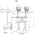
- Figure 2 is a schematic diagram of the configuration for supplying cleaning liquid to the cleaning liquid reservoir 118 of each of the probe cleaning mechanisms 14 and 24.
- the automated analyzer includes a cleaning liquid supply pump 201, a cleaning liquid supply syringe 204 equipped with a plunger 220, branch pipes 207, 208, cleaning liquid remaining amount sensors 205, 206, solenoid valves 209-214, a control unit 21, and a memory unit 22.
- the probe cleaning mechanisms 14, 24 have lower openings for discharging overflowing cleaning liquid.
- the example in Figure 2 shows a schematic diagram of the cleaning mechanisms that supply cleaning liquid to the cleaning liquid storage units 118 of the two probe cleaning mechanisms 14, 24.
- the first cleaning liquid supplied from the cleaning liquid supply pump 201 can be automatically supplied to the probe cleaning mechanisms 14, 24, and the second cleaning liquid stored in the cleaning liquid storage tanks 202, 203 can also be supplied to the probe cleaning mechanisms 14, 24.
- the automatic analyzer has a heterogeneous cleaning liquid region in which different types of cleaning liquid, i.e., the first cleaning liquid and the second cleaning liquid, can exist. Note that in this embodiment, the first cleaning liquid and the second cleaning liquid do not exist simultaneously in the heterogeneous cleaning liquid region.
- the cleaning liquid supply syringe 204 (or a configuration in which the cleaning liquid supply syringe 204 is combined with the cleaning liquid supply pump 201, solenoid valves 209 to 214, etc.) functions as a liquid delivery mechanism, delivering the first and second cleaning liquids for cleaning each of the dispensing probes.
- the cleaning liquid in the different cleaning liquid area can be replaced by operating the cleaning liquid supply syringe 204.
- the control unit 21 includes, for example, a processor as a computing means.
- the storage unit 22 includes, for example, a storage medium such as a semiconductor memory device and a magnetic disk device. Some or all of the storage medium may be non-transitory storage media.
- the memory unit 22 stores flow path parameters.
- the flow path parameters indicate the types of cleaning liquid present in the different cleaning liquid area.
- the automated analyzer stores flow path parameters and knows the type of cleaning liquid in the heterogeneous cleaning liquid area, making it possible to determine the timing when additional or repeated replacement of the cleaning liquid is required due to non-stationary processing. This makes it possible to reduce the frequency of replacement of the cleaning liquid, thereby reducing, for example, the amount of cleaning liquid consumed and/or shortening the time until analysis can begin.
- the flow path parameter can take one of two values, for example, "first cleaning liquid” or "second cleaning liquid.”
- the memory unit 22 can be said to store whether the first cleaning liquid or the second cleaning liquid is present in the different cleaning liquid area.
- the initial value of the flow path parameter is the first cleaning liquid.
- the memory unit 22 may store a computer program in addition to the above-mentioned flow path parameters.
- the processor of the control unit 21 executes this computer program, causing the automatic analyzer to perform the functions described in this embodiment.
- the source of the second cleaning liquid can be switched between the cleaning liquid storage tank 202 and the cleaning liquid storage tank 203.
- the first cleaning liquid is, for example, water or a neutral detergent
- the second cleaning liquid is, for example, a special alkaline or acidic cleaning liquid.
- two storage tanks for the second cleaning liquid (cleaning liquid storage tank 202 and cleaning liquid storage tank 203) are installed, and a changeover function for the second cleaning liquid is provided.
- the cleaning liquid supply operation is the same even in a configuration in which the second cleaning liquid is stored in one cleaning liquid storage tank 202 and there is one cleaning liquid reservoir 118.
- the automated analyzer can selectively execute multiple types of reset operations as the reset operation that moves the plunger 220 to the initial position (the upper limit in this embodiment).
- the multiple types of reset operations include a first reset operation and a second reset operation that delivers a smaller amount of liquid than the first reset operation.
- the first reset operation is a full reset operation in which the plunger 220 moves a full stroke to check the sensor and/or mechanism.
- the full reset operation for example, first moves the plunger 220 from an arbitrary position to the upper limit point. It also includes an operation in which the plunger 220 moves to the lower limit point (maximum suction position) and then the plunger 220 moves to the upper limit point (maximum discharge position). This operation makes it possible to check, for example, whether the cleaning liquid supply syringe 204 is operating normally.
- the short reset operation includes, for example, the following operations: First, the plunger 220 moves to the upper limit point. After a sensor or the like detects that the plunger 220 is at the upper limit point, the plunger 220 moves slightly toward the lower limit point (i.e., performs a slight suction) until it is detected that the plunger 220 is not at the upper limit point. After it is detected that the plunger 220 is not at the upper limit point, the plunger 220 moves again to the upper limit point. This operation makes it possible to check whether the sensor or the like is operating normally.
- the amount of cleaning fluid (e.g., second cleaning fluid) consumed here varies greatly depending on the amount of movement of the plunger 220 of the cleaning fluid supply syringe 204. In the case of a full reset, the amount of movement of the plunger 220 is large, and in the case of a short reset, the amount of movement of the plunger 220 is small. Therefore, in the case of a short reset, in which the movement of the plunger 220 is small, the amount of second cleaning fluid consumed is small.
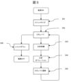
- FIG. 3 is a flowchart explaining the transition of the device status from power ON to power OFF in the automatic analyzer according to the first embodiment.
- the device status is stored, for example, in the memory unit 22 and updated by the control unit 21.
- the device status transitions to initialize (step 301) as a startup preparation operation, and then transitions to standby (step 302).
- the device status transitions to analysis preparation (step 303), and then transitions to analysis operation (step 304), and the analysis operation begins.
- the device status transitions to standby transition (step 305), and then transitions back to standby.
- the device status transitions to shutdown (step 306) as a preparation for termination, and the power is turned off when the shutdown process is completed.
- the device status refers to each state from step 301 to step 306. However, other device statuses may also be included.
- Figure 4 is a flowchart for determining which reset operation to select based on the device status and flow path parameters.
- the control unit checks the device status (step 402). If the device status is initialized, the automatic analyzer executes a full reset (step 405).
- the control unit checks the flow path parameters (step 403). If the flow path parameters are the second cleaning liquid, the automatic analyzer executes a short reset (step 404). If the flow path parameters are the first cleaning liquid, a full reset is executed (step 405).
- the automatic analyzer controls the liquid delivery mechanism based on the flow path parameters (i.e., the type of cleaning liquid stored in the memory unit 22).
- the automatic analyzer selects full reset or short reset based on the flow path parameters and has the liquid delivery mechanism execute it.
- the flow path parameter is the second cleaning liquid
- a short reset is selected, so that the consumption of the second cleaning liquid can be reduced.
- the second cleaning liquid e.g., a special alkaline or acidic cleaning liquid
- the first cleaning liquid e.g., water or a neutral detergent
- Figure 5 is a flowchart for determining whether or not a cleaning liquid replacement operation is required and which cleaning liquid to replace based on the device status and flow path parameters.
- control unit checks the device status (step 502). If the device status is other than shutdown, the control unit checks the flow path parameters (step 503). If the flow path parameters are the second cleaning liquid, the process is completed without performing the cleaning liquid replacement operation.
- the control unit updates the flow path parameter stored in the memory unit to the second cleaning liquid (step 505).
- the memory unit 22 stores, as a flow path parameter, the fact that the type of cleaning liquid present in the different cleaning liquid area is the second cleaning liquid.
- the control unit checks the device status (step 502), and if the device status is shutdown, replaces the cleaning liquid in the different cleaning liquid area with the first cleaning liquid (step 506).
- the control unit then updates the flow path parameters stored in the memory unit to the first cleaning liquid (step 507).
- the memory unit 22 stores as flow path parameters that the type of cleaning liquid present in the different cleaning liquid area is the first cleaning liquid.
- the automated analyzer replaces the cleaning solution during the shutdown operation, so the type of cleaning solution present in the different cleaning solution area can always be consistent the next time the analyzer is started.
- the automatic analyzer determines the following based on the device status and the flow path parameters: - whether or not the cleaning solution present in the region of the different cleaning solution needs to be replaced; and - the type of cleaning fluid delivered for replacement, According to this operation, the efficiency of the cleaning operation can be improved, and as a result, the consumption of the cleaning liquid can be reduced.
- the second cleaning liquid is always stored in the different cleaning liquid area, except when the device status is a shutdown operation. Therefore, when the flow path parameter is the second cleaning liquid, a replacement operation is not necessary, but in the process of FIG. 5, such unnecessary replacement operation can be omitted by the judgment in step 503, thereby reducing the consumption of the second cleaning liquid.
- both the necessity for replacement and the type of cleaning liquid are determined based on the device status and flow path parameters, but a modified version is also possible in which only one of the necessity for replacement and the type of cleaning liquid is determined. In that case, the other may be determined based on other criteria.
- Figure 6 is a diagram that lists in chronological order the device status during each operation, the behavior of the control unit, the operation on the automatic analyzer, the cleaning liquid filling the different cleaning liquid area, the flow path parameters held by the memory unit, etc.
- the judgment of the control unit when checking each piece of information follows Figures 4 and 5, respectively.
- Figure 6 "F. Reset” indicates a full reset, and "S. Reset” indicates a short reset.
- the device is powered on (step 601) and the initialization operation begins.
- the control unit determines which reset operation to select. In the process of FIG. 4, the control unit checks the device status (step 602). Since the device status is initialization, the process of FIG. 4 branches to step 405 and a full reset is selected (step 603).
- the control unit judges whether or not a cleaning liquid replacement operation is required.
- the control unit checks the next device status (step 604). Since the next device status is standby, the flow path parameters are then checked (step 605). Since the flow path parameters are the first cleaning liquid, the process of FIG. 5 branches to step 504, and the cleaning liquid in the different cleaning liquid area is replaced with the second cleaning liquid (step 606). The control unit confirms that the flow path replacement has been completed normally (step 607). Thereafter, the control unit updates the flow path parameters stored in the memory unit to the second cleaning liquid (step 608). After the replacement, the device status transitions to standby.
- the control unit determines which reset operation to select. In the process of FIG. 4, the control unit checks the device status (step 609). Since the device status is analysis preparation, which is not initialization, the control unit checks the flow path parameters (step 610). Since the flow path parameter is the second cleaning liquid, the process of FIG. 4 branches to step 404, and a short reset is selected (step 611).
- the control unit determines whether or not a replacement operation of the cleaning liquid in the different cleaning liquid area is required. In the process of FIG. 5, the control unit checks the next equipment status (step 612). Since the next equipment status is analysis operation, it then checks the flow path parameters (step 613). Since the flow path parameters are the second cleaning liquid, steps 504 and 505 in FIG. 5 are not executed, i.e., the cleaning liquid is not replaced and the equipment status transitions to analysis operation.
- the control unit determines which reset operation to select. In the process of FIG. 4, the control unit checks the device status (step 614). Since the device status is standby transition, which is other than initialization, the control unit checks the flow path parameters (step 615). Since the flow path parameter is the second cleaning liquid, the process of FIG. 4 branches to step 404, and short reset is selected (step 616).
- the control unit judges whether or not a replacement operation of the cleaning liquid in the different cleaning liquid area is required.
- the control unit checks the next equipment status (step 617). Since the next equipment status is standby, the flow path parameters are then checked (step 618). Since the flow path parameters are the second cleaning liquid, steps 504 and 505 in FIG. 5 are not executed, i.e., the cleaning liquid is not replaced and the equipment status transitions to standby.
- the control unit determines which reset operation to select. In the process of FIG. 4, the control unit checks the device status (step 619). Since the device status is shutdown and not initialized, the control unit checks the flow path parameters (step 620). Since the flow path parameter is the second cleaning liquid, the process of FIG. 4 branches to step 404, and a short reset is selected (step 621).
- the control unit determines whether or not a replacement operation of the cleaning liquid is required (there is no transition of the device status here, but in the case of shutdown, the process of FIG. 5 continues). In the process of FIG. 5, the control unit checks the next device status (step 622). Here, the next device status is treated as being shutdown. Because the next device status is shutdown, the process of FIG. 5 branches to step 506, and the cleaning liquid is replaced with the first cleaning liquid (step 623). The control unit confirms that the flow path replacement has been completed normally (step 624). After that, the control unit updates the flow path parameters stored in the memory unit to the first cleaning liquid (step 625). The power to the device is then turned off.
- FIG. 7 is a diagram showing the chronological order of the actions taken when an abnormality is detected during operation of the automatic analyzer according to this embodiment. The judgments made by the control unit when checking each piece of information follow those shown in FIGS. 4 and 5. Note that in FIG. 7, “F. Reset” indicates a full reset, and “S. Reset” indicates a short reset.
- step 701 the control unit detects some kind of abnormality and issues an alarm (step 701). As a result, the control unit cannot confirm that the flow path replacement has been completed successfully (step 702), and does not update the flow path parameters to the second cleaning liquid (step 703). After that, the control unit interrupts the flowchart in FIG. 5, and the device status transitions to standby.
- step 606 refers to "before plunger 220 has completed its operation.” This is because if the replacement operation of the cleaning liquid stops before plunger 220 has completed its operation, the first cleaning liquid and the second cleaning liquid will end up being partially mixed in the flow path.
- the control unit determines which reset operation to select. In the process of FIG. 4, the control unit checks the device status (step 704). Since the device status is analysis preparation, which is other than initialization, the control unit checks the flow path parameters (step 705). Since the flow path parameter is the first cleaning solution, the process of FIG. 4 branches to step 405, and a full reset is selected (step 706).
- the control unit judges whether or not a replacement operation of the cleaning liquid in the different cleaning liquid area is required.
- the control unit checks the next equipment status (step 707). Since the next equipment status is analysis operation, the flow path parameters are then checked (step 708). Since the flow path parameters are the first cleaning liquid, steps 504 and 505 in FIG. 5 are executed, and the cleaning liquid in the different cleaning liquid area is replaced with the second cleaning liquid (step 709).
- the control unit confirms that the flow path replacement has been completed normally (step 710). Thereafter, the control unit updates the flow path parameters stored in the memory unit to the second cleaning liquid (step 711). After the replacement, the equipment status transitions to operation.
- step 607 If the alarm is issued after step 607 has been performed, the replacement operation of the cleaning liquid has been completed and the flow path parameters have been updated, so the replacement operation can be considered to have been completed normally.
- a full reset is performed at the appropriate time if an abnormality occurs in the device. Or, even if the cleaning solution replacement operation is interrupted, a full reset is performed again before analysis begins, and the cleaning solution replacement operation is carried out. Also, in either case, the number of replacement operations is reduced, so compared to the conventional configuration (in which more replacement operations are performed), the amount of cleaning solution consumed is reduced and the reset time (the time until analysis begins) is shortened.
- the automatic analyzer may be capable of using three or more types of cleaning liquid.
Landscapes
- Physics & Mathematics (AREA)
- Health & Medical Sciences (AREA)
- Life Sciences & Earth Sciences (AREA)
- Chemical & Material Sciences (AREA)
- Analytical Chemistry (AREA)
- Biochemistry (AREA)
- General Health & Medical Sciences (AREA)
- General Physics & Mathematics (AREA)
- Immunology (AREA)
- Pathology (AREA)
- Automatic Analysis And Handling Materials Therefor (AREA)
Priority Applications (2)
| Application Number | Priority Date | Filing Date | Title |
|---|---|---|---|
| JP2025537755A JPWO2025028116A1 (https=) | 2023-07-31 | 2024-07-01 | |
| CN202480014348.8A CN120752539A (zh) | 2023-07-31 | 2024-07-01 | 自动分析装置及其控制方法 |
Applications Claiming Priority (2)
| Application Number | Priority Date | Filing Date | Title |
|---|---|---|---|
| JP2023124911 | 2023-07-31 | ||
| JP2023-124911 | 2023-07-31 |
Publications (1)
| Publication Number | Publication Date |
|---|---|
| WO2025028116A1 true WO2025028116A1 (ja) | 2025-02-06 |
Family
ID=94394454
Family Applications (1)
| Application Number | Title | Priority Date | Filing Date |
|---|---|---|---|
| PCT/JP2024/023763 Pending WO2025028116A1 (ja) | 2023-07-31 | 2024-07-01 | 自動分析装置およびその制御方法 |
Country Status (3)
| Country | Link |
|---|---|
| JP (1) | JPWO2025028116A1 (https=) |
| CN (1) | CN120752539A (https=) |
| WO (1) | WO2025028116A1 (https=) |
Citations (6)
| Publication number | Priority date | Publication date | Assignee | Title |
|---|---|---|---|---|
| JPH06207944A (ja) * | 1993-01-11 | 1994-07-26 | Hitachi Ltd | 洗浄機能付き自動分析装置 |
| JPH06213907A (ja) * | 1993-01-18 | 1994-08-05 | Hitachi Ltd | 洗剤洗浄可能な分注装置及びその洗浄方法 |
| JP2014002099A (ja) * | 2012-06-20 | 2014-01-09 | Shimadzu Corp | 原子吸光分光光度計のオートサンプラ |
| JP2017067509A (ja) * | 2015-09-29 | 2017-04-06 | 株式会社日立ハイテクノロジーズ | 自動分析装置 |
| JP2018017676A (ja) * | 2016-07-29 | 2018-02-01 | 日本電子株式会社 | 自動分析装置及びプログラム |
| JP2021081213A (ja) * | 2019-11-14 | 2021-05-27 | 株式会社島津製作所 | 血液凝固分析装置、及び分注ノズルの洗浄方法 |
-
2024
- 2024-07-01 JP JP2025537755A patent/JPWO2025028116A1/ja active Pending
- 2024-07-01 WO PCT/JP2024/023763 patent/WO2025028116A1/ja active Pending
- 2024-07-01 CN CN202480014348.8A patent/CN120752539A/zh active Pending
Patent Citations (6)
| Publication number | Priority date | Publication date | Assignee | Title |
|---|---|---|---|---|
| JPH06207944A (ja) * | 1993-01-11 | 1994-07-26 | Hitachi Ltd | 洗浄機能付き自動分析装置 |
| JPH06213907A (ja) * | 1993-01-18 | 1994-08-05 | Hitachi Ltd | 洗剤洗浄可能な分注装置及びその洗浄方法 |
| JP2014002099A (ja) * | 2012-06-20 | 2014-01-09 | Shimadzu Corp | 原子吸光分光光度計のオートサンプラ |
| JP2017067509A (ja) * | 2015-09-29 | 2017-04-06 | 株式会社日立ハイテクノロジーズ | 自動分析装置 |
| JP2018017676A (ja) * | 2016-07-29 | 2018-02-01 | 日本電子株式会社 | 自動分析装置及びプログラム |
| JP2021081213A (ja) * | 2019-11-14 | 2021-05-27 | 株式会社島津製作所 | 血液凝固分析装置、及び分注ノズルの洗浄方法 |
Also Published As
| Publication number | Publication date |
|---|---|
| CN120752539A (zh) | 2025-10-03 |
| JPWO2025028116A1 (https=) | 2025-02-06 |
Similar Documents
| Publication | Publication Date | Title |
|---|---|---|
| CN104024867B (zh) | 自动分析装置和试样分注探针清洗方法 | |
| CN104769438B (zh) | 自动分析装置 | |
| JP6877629B2 (ja) | 自動分析装置および自動分析装置の流路詰まり検出方法 | |
| JP6453219B2 (ja) | 自動分析装置 | |
| WO2017141627A1 (ja) | 自動分析装置および分注プローブの洗浄方法 | |
| JP6247935B2 (ja) | 自動分析装置 | |
| JP6635661B2 (ja) | 自動分析装置及び試料希釈攪拌方法 | |
| JP6928712B2 (ja) | 自動分析装置 | |
| JP4672034B2 (ja) | 自動分析装置 | |
| WO2025028116A1 (ja) | 自動分析装置およびその制御方法 | |
| CN114556111B (zh) | 自动分析装置 | |
| CN107835942B (zh) | 自动分析装置及液体容器 | |
| JP7459095B2 (ja) | 自動分析装置、および自動分析装置の運転方法 | |
| JP2009145091A (ja) | 自動分析装置 | |
| JPH1073601A (ja) | 自動分析装置 | |
| JP7825732B2 (ja) | 自動分析装置およびプローブの洗浄方法 | |
| JPWO2021005835A5 (https=) | ||
| EP3842809B1 (en) | Automatic analysis device and automatic analysis system | |
| US20240201215A1 (en) | Automatic Analyzer | |
| JPWO2025028116A5 (https=) | ||
| JPWO2020066523A1 (ja) | 自動分析装置 |
Legal Events
| Date | Code | Title | Description |
|---|---|---|---|
| 121 | Ep: the epo has been informed by wipo that ep was designated in this application |
Ref document number: 24848775 Country of ref document: EP Kind code of ref document: A1 |
|
| ENP | Entry into the national phase |
Ref document number: 2025537755 Country of ref document: JP Kind code of ref document: A |
|
| WWE | Wipo information: entry into national phase |
Ref document number: 2025537755 Country of ref document: JP |
|
| WWE | Wipo information: entry into national phase |
Ref document number: 202480014348.8 Country of ref document: CN |
|
| WWP | Wipo information: published in national office |
Ref document number: 202480014348.8 Country of ref document: CN |
|
| NENP | Non-entry into the national phase |
Ref country code: DE |