WO2025027731A1 - エンジン - Google Patents
エンジン Download PDFInfo
- Publication number
- WO2025027731A1 WO2025027731A1 PCT/JP2023/027904 JP2023027904W WO2025027731A1 WO 2025027731 A1 WO2025027731 A1 WO 2025027731A1 JP 2023027904 W JP2023027904 W JP 2023027904W WO 2025027731 A1 WO2025027731 A1 WO 2025027731A1
- Authority
- WO
- WIPO (PCT)
- Prior art keywords
- engine
- cylinder chamber
- engine block
- fastening
- cooling
- Prior art date
- Legal status (The legal status is an assumption and is not a legal conclusion. Google has not performed a legal analysis and makes no representation as to the accuracy of the status listed.)
- Pending
Links
Images









Classifications
-
- F—MECHANICAL ENGINEERING; LIGHTING; HEATING; WEAPONS; BLASTING
- F01—MACHINES OR ENGINES IN GENERAL; ENGINE PLANTS IN GENERAL; STEAM ENGINES
- F01P—COOLING OF MACHINES OR ENGINES IN GENERAL; COOLING OF INTERNAL-COMBUSTION ENGINES
- F01P3/00—Liquid cooling
- F01P3/02—Arrangements for cooling cylinders or cylinder heads
-
- F—MECHANICAL ENGINEERING; LIGHTING; HEATING; WEAPONS; BLASTING
- F02—COMBUSTION ENGINES; HOT-GAS OR COMBUSTION-PRODUCT ENGINE PLANTS
- F02B—INTERNAL-COMBUSTION PISTON ENGINES; COMBUSTION ENGINES IN GENERAL
- F02B75/00—Other engines
- F02B75/28—Engines with two or more pistons reciprocating within same cylinder or within essentially coaxial cylinders
-
- F—MECHANICAL ENGINEERING; LIGHTING; HEATING; WEAPONS; BLASTING
- F02—COMBUSTION ENGINES; HOT-GAS OR COMBUSTION-PRODUCT ENGINE PLANTS
- F02F—CYLINDERS, PISTONS OR CASINGS, FOR COMBUSTION ENGINES; ARRANGEMENTS OF SEALINGS IN COMBUSTION ENGINES
- F02F1/00—Cylinders; Cylinder heads
- F02F1/02—Cylinders; Cylinder heads having cooling means
- F02F1/10—Cylinders; Cylinder heads having cooling means for liquid cooling
Definitions
- the present invention relates to engines, and in particular to opposed piston engines.
- the small combustion chamber volume makes it difficult to achieve a high compression ratio, and insulating the combustion chamber also poses problems.
- the intake and exhaust valves of conventional opposed piston engines open directly into the combustion chamber, which has the drawback of making the combustion chamber larger in volume.
- JP 2007-46534 A Japanese Patent Application Publication No. 8-93498 Patent No. 5508604
- the opposed piston engine described in the aforementioned patent document has one combustion chamber, and generates kinetic energy by the reciprocating motion of two pistons inside the combustion chamber.
- the combustion chamber is enlarged or multiple combustion chambers are provided in order to improve the output of the opposed piston engine, the engine configuration becomes more complex.
- the engine is constructed by fastening multiple engine blocks together, the number of fastening members that fasten the engine blocks together increases, which can lead to problems such as the configuration for arranging the fastening members becoming more complex or larger.
- the present invention was made in consideration of these problems, and the object of the present invention is to provide an engine that can prevent the fastening configuration of the engine block from becoming too complicated.
- the engine of the present invention is characterized by having a cylinder chamber formed by multiple engine blocks, and a cooling flow passage formed near the cylinder chamber and through which a cooling fluid flows, and by disposing a part of the fastening member that fastens the engine blocks together in the cooling flow passage.
- the engine block has a first engine block and a second engine block fastened to the first engine block by the fastening member
- the cylinder chamber has a first cylinder chamber and a second cylinder chamber adjacent to the first cylinder chamber, pistons arranged to reciprocate inside the first cylinder chamber and pistons arranged to reciprocate inside the second cylinder chamber
- the cooling flow passage is configured to cool the first cylinder chamber and the second cylinder chamber
- the first cylinder chamber and the second cylinder chamber are spaces formed by joining the first engine block and the second engine block
- a part of the fastening member is disposed in the cooling flow passage.
- the engine of the present invention is also characterized in that a seal member is interposed between the fastening member and the engine block.
- the engine of the present invention is also characterized in that a seal member is interposed between the fastening member and the first engine block and between the fastening member and the second engine block.
- the first engine block includes a first cooling flow passage that is a part of the cooling flow passage, and a first fastening hole that is connected to the first cooling flow passage and through which the fastening member is inserted
- the second engine block includes a second cooling flow passage that is another part of the cooling flow passage, and a second fastening hole that is connected to the second cooling flow passage and through which the fastening member is inserted
- the seal member includes a first seal member and a second seal member, and the first seal member is interposed between the fastening member and the first fastening hole, and the second seal member is interposed between the fastening member and the second fastening hole.
- the engine of the present invention is characterized in that the cooling passage in the portion where the fastening member is arranged is formed between the first cylinder chamber and the second cylinder chamber.
- the engine of the present invention is also characterized in that the fastening member is a stud bolt and the sealing member is an O-ring.
- the engine of the present invention is characterized by having a cylinder chamber formed by multiple engine blocks, and a cooling passage formed near the cylinder chamber and through which a cooling fluid flows, and by arranging some of the fastening members fastening the engine blocks together in the cooling passage.
- the cooling passage also serves as an area for arranging the fastening members, thereby making it possible to reduce the size of the engine.
- the engine block includes a first engine block and a second engine block fastened to the first engine block by the fastening member
- the cylinder chamber includes a first cylinder chamber and a second cylinder chamber adjacent to the first cylinder chamber, pistons arranged to reciprocate inside the first cylinder chamber, pistons arranged to reciprocate inside the second cylinder chamber
- the cooling flow passage is configured to cool the first cylinder chamber and the second cylinder chamber
- the first cylinder chamber and the second cylinder chamber are spaces formed by joining the first engine block and the second engine block
- a part of the fastening member is disposed in the cooling flow passage.
- the cooling flow passage also serves as an area for arranging the fastening member, so that the first cylinder chamber and the second cylinder chamber can be brought closer to each other, and the engine can be made more compact.
- the engine of the present invention is also characterized in that a seal member is interposed between the fastening member and the engine block. According to the engine of the present invention, by interposing a seal member between the fastening member and the engine block, it is possible to prevent the cooling fluid from leaking out of the cooling passage.
- the engine of the present invention is also characterized in that a seal member is interposed between the fastening member and the first and second engine blocks. According to the engine of the present invention, by interposing a seal member between the fastening member and the first and second engine blocks, it is possible to prevent the cooling fluid from leaking out of the cooling passages.
- the first engine block includes a first cooling flow passage that is a part of the cooling flow passage, and a first fastening hole that is a hole that communicates with the first cooling flow passage and through which the fastening member is inserted
- the second engine block includes a second cooling flow passage that is another part of the cooling flow passage, and a second fastening hole that is a hole that communicates with the second cooling flow passage and through which the fastening member is inserted
- the seal member includes a first seal member and a second seal member, and the first seal member is interposed between the fastening member and the first fastening hole, and the second seal member is interposed between the fastening member and the second fastening hole.
- the cooling passage in the portion where the fastening member is arranged is formed between the first cylinder chamber and the second cylinder chamber.
- the fastening member can be arranged in the space formed between the first cylinder chamber and the second cylinder chamber, and the overall engine can be made compact.
- the fastening member is a stud bolt
- the sealing member is an O-ring.
- FIG. 1 is a perspective view showing an engine according to an embodiment of the present invention.
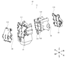
- 1 is a diagram showing an engine according to an embodiment of the present invention, and is an exploded perspective view of an engine block as seen from the front.
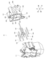
- FIG. 1 is an exploded perspective view of an engine block according to an embodiment of the present invention, seen from the rear.
- FIG. 1 is a diagram showing an engine according to an embodiment of the present invention, and is a perspective view showing an engine section.
- FIG. 2 is a cross-sectional view showing a wall portion of an engine block which defines a cylinder chamber and an extension space, showing an engine according to an embodiment of the present invention.
- FIG. 1 is a diagram showing an engine according to an embodiment of the present invention, and is an exploded perspective view of an engine block as seen from the front.
- FIG. 1 is an exploded perspective view of an engine block according to an embodiment of the present invention, seen from the rear.
- FIG. 1 is a diagram showing an engine according to an embodiment of the present invention, and is
- FIG. 2 is an exploded perspective view showing a fastening structure between a first engine block and a second engine block, as viewed from the rear, of an engine according to an embodiment of the present invention.
- FIG. 2 is an exploded front perspective view showing the engine according to the embodiment of the present invention, illustrating a fastening structure between a first engine block and a second engine block.
- FIG. 2 is a diagram showing an engine according to an embodiment of the present invention, illustrating a contact surface of a first engine block.
- FIG. 2 is a diagram showing an engine according to an embodiment of the present invention, illustrating a contact surface of a second engine block.
- FIG. 1 is a diagram showing an engine according to an embodiment of the present invention, and is a perspective view showing a stud bolt and an O-ring.
- FIG. 1 is an exploded perspective view showing an engine according to an embodiment of the present invention, illustrating a stud bolt and an O-ring.
- FIG. 1 is a diagram showing an engine according to an embodiment of the present invention, and is a cross-sectional view showing a schematic configuration of a cooling passage and the like.
- FIG. 2 is a cross-sectional view showing an engine according to an embodiment of the present invention, in which a stud bolt penetrates a cooling passage.
- FIG. 2 is a cross-sectional view showing a relation between a first fastening hole and a stud bolt of an engine according to an embodiment of the present invention.
- FIG. 2 is a cross-sectional view showing a relation between a second fastening hole and a stud bolt according to an embodiment of the present invention.
- FIG. 2 is a rear perspective view of an engine according to an embodiment of the present invention, showing a stud bolt and a cooling passage.
- FIG. 2 is a front perspective view of an engine according to an embodiment of the present invention, showing a stud bolt and a cooling passage.
- the front-rear direction refers to the direction in which pistons, which will be described later, reciprocate.
- the left-right direction refers to the direction in which cylinder spaces, which will be described later, are arranged.
- the same components are generally given the same reference numerals, and repeated description will be omitted.
- the configuration described in the claims will be mainly illustrated and described. Therefore, parts of the engine 10 other than the relevant configuration, such as the plug, crankshaft rotation synchronization mechanism, lubricating oil supply mechanism, fuel supply mechanism, electrical equipment, etc., are not illustrated.
- Figure 1 is a perspective view of the engine 10.
- Engine 10 is an opposed-piston engine with multiple pistons arranged opposite each other. The internal configuration and operation of engine 10 will be described later with reference to Figure 2 and subsequent figures.
- the engine 10 is configured to operate using gasoline, diesel, hydrogen, or the like as fuel.
- the engine 10 can be used as a drive source for various devices.
- the engine 10 is used as a drive source for vehicles, generators, water heaters, flying devices, drones, series hybrid drones, parallel hybrid drones, and the like.
- a series hybrid drone is a drone in which a generator is operated by the engine 10, a motor is rotated by the power generated by the generator, a rotor is rotated by the motor, and the aircraft is levitated in the air by the lift generated by the rotation of the rotor.
- a parallel hybrid drone is a drone in which a main rotor is mechanically rotated by the engine, and the aircraft is levitated by the lift generated by the rotation of the main rotor.
- the engine 10 of this embodiment is an opposed piston type engine, and is lightweight and has low vibration, making it suitable as a drive source for series hybrid drones, parallel hybrid drones, and the like.
- the engine 10 has an engine block 11, which is the main body.
- the engine block 11 is made of, for example, a cast aluminum alloy.
- the engine block 11 is made up of a first engine block 111, a second engine block 112, a third engine block 113, and a fourth engine block 114. Each of these parts is fastened to each other by fastening members 18, which will be described later.
- a third crankshaft 163 and a fourth crankshaft 173 extend from the right side of the engine 10. Rotational power can be extracted to the outside from the third crankshaft 163 and the fourth crankshaft 173.
- shafts can also be extended from the left side of the engine 10, and power can also be extracted to the outside from these shafts.
- Figure 2 is an exploded perspective view of the engine block 11 as seen from the front.
- Figure 3 is an exploded perspective view of the engine block 11 as seen from the rear.
- the engine block 11 has, from the front side, a third engine block 113, a first engine block 111, a second engine block 112, and a fourth engine block 114.
- the first engine block 111 to the fourth engine block 114 are fastened to each other by fastening members 18, which will be described later.
- the first engine block 111 and the second engine block 112 have a first cylinder chamber 121 and a second cylinder chamber 122 formed therein, which are cylinder chambers 12.
- the configuration of the first engine block 111 and the second engine block 112 will be described later with reference to Figures 6 and 7, etc.
- the third engine block 113 houses the third crankshaft 163 and other components.
- the third crankshaft 163 and other components are rotatably held by a semicircular crank holder 30 formed at the rear of the third engine block 113 and a semicircular crank holder 31 formed at the front of the first engine block 111.
- the fourth engine block 114 houses the fourth crankshaft 173 and other components.
- the fourth crankshaft 173 and other components are rotatably held by a semicircular crank holder 33 formed in the front of the fourth engine block 114 and a semicircular crank holder 32 formed in the rear of the second engine block 112.
- Figure 4 is a perspective view of the engine section 13 built into the engine block 11 described above, seen from the front.
- the engine section 13 has a first engine section 14, a second engine section 15, a third engine section 16, and a fourth engine section 17.
- the first engine section 14 and the second engine section 15 form one opposing engine section.
- the third engine section 16 and the fourth engine section 17 form one opposing engine section.
- the cylinder chamber 12 has a first cylinder chamber 121 and a second cylinder chamber 122 adjacent to the first cylinder chamber 121.
- the first cylinder chamber 121 and the second cylinder chamber 122 are adjacent to each other in the left-right direction.
- the first cylinder chamber 121 and the second cylinder chamber 122 are indicated by dotted lines.
- a first piston 141 and a second piston 151 are arranged to reciprocate, facing each other.
- a third piston 161 and a fourth piston 171 are arranged to reciprocate, facing each other.
- the first engine section 14 has a first piston 141, a first connecting rod 142, and a first crankshaft 143.
- the first connecting rod 142 rotatably connects the first piston 141 and the first crankshaft 143.
- the second engine section 15 is disposed so as to face the first engine section 14.
- the second engine section 15 has a second piston 151, a second connecting rod 152, and a second crankshaft 153.
- the second connecting rod 152 rotatably connects the second piston 151 and the second crankshaft 153.
- the third engine section 16 has a third piston 161, a third connecting rod 162, and a third crankshaft 163.
- the third connecting rod 162 rotatably connects the third piston 161 and the third crankshaft 163.
- the fourth engine section 17 is disposed so as to face the third engine section 16.
- the fourth engine section 17 has a fourth piston 171, a fourth connecting rod 172, and a fourth crankshaft 173.
- the fourth connecting rod 172 rotatably connects the fourth piston 171 and the fourth crankshaft 173.
- the first crankshaft 143 of the first engine section 14 and the third crankshaft 163 of the third engine section 16 are integrally continuous. Therefore, the first piston 141 of the first engine section 14 and the third piston 161 of the third engine section 16 reciprocate simultaneously.
- the second crankshaft 153 of the second engine section 15 and the fourth crankshaft 173 of the fourth engine section 17 are integrally continuous. Therefore, the second piston 151 of the second crankshaft 153 and the fourth piston 171 of the fourth engine section 17 reciprocate simultaneously.
- the engine section 13 is configured with an opposed engine section consisting of a first engine section 14 and a second engine section 15, and an opposed engine section consisting of a third engine section 16 and a fourth engine section 17, arranged side by side in the left-right direction.
- the first engine section 14 and the third engine section 16 rotate the first crankshaft 143 and the third crankshaft 163.
- the second engine section 15 and the fourth engine section 17 rotate the second crankshaft 153 and the fourth crankshaft 173.
- the first engine section 14 and the second engine section 15 of the engine section 13 configured as described above operate as follows. First, during the intake stroke, the first piston 141 and the second piston 151 move from the center to the outside inside the first cylinder chamber 121, and a mixture of fuel and air is introduced into the first cylinder chamber 121. Next, during the compression stroke, the first piston 141 and the second piston 151 are pushed toward the center by the inertia of the rotating first crankshaft 143 and the second crankshaft 153, and the mixture is compressed inside the first cylinder chamber 121.
- an ignition plug (not shown) ignites in the first cylinder chamber 121, and the mixture is burned inside the first cylinder chamber 121, and the first piston 141 and the second piston 151 are pushed to the outer end, which is the bottom dead center. Then, during the exhaust stroke, the first piston 141 and the second piston 151 are pushed inward by the inertia of the rotating first crankshaft 143 and the second crankshaft 153, and the post-combustion gas present inside the first cylinder chamber 121 is exhausted to the outside.
- the stroke can be divided by two first pistons 141 and 151 that reciprocate inside one first cylinder chamber 121. Therefore, the compression ratio of the mixed gas can be increased compared to a normal engine.
- the first piston 141 and the second piston 151 face each other inside the first cylinder chamber 121, the cylinder head required in a normal engine is not required, and the configuration of the engine section 13 is simple and lightweight.
- each member constituting the engine section 13, i.e., the first piston 141 and the second piston 151, the first crankshaft 143 and the second crankshaft 153, etc. are arranged opposite each other and operate in such a manner as to face each other.
- the vibrations generated from each member of the engine section 13 are offset, and the vibrations generated from the entire engine section 13 to the outside can be reduced. Therefore, by mounting an engine section 13 having such a structure on a flying device, it is possible to achieve a smaller, lighter, and less-vibrating flying device.
- low vibration can prevent adverse effects on precision equipment such as attitude control, motor output control, and other arithmetic and control devices, and GPS sensors. It can also prevent damage to delivery packages transported by the flight device caused by vibration.
- the engine section 13 is equipped with a reverse synchronization mechanism (not shown).
- the reverse synchronization mechanism reverses the rotational directions of the first crankshaft 143 and the second crankshaft 153. Furthermore, the reverse synchronization mechanism synchronizes the reciprocating motion of the first piston 141 and the second piston 151. Therefore, in the engine section 13, the first crankshaft 143 and the second crankshaft 153 have opposite rotational directions.
- FIG. 5 is a cross-sectional view taken along the line B-B in FIG. 4, showing the wall of the engine block 11 that defines the first cylinder chamber 121 and the first extension space 331.
- the first cylinder chamber 121 is a space having a substantially cylindrical shape.
- the first cylinder chamber 121 has a first cylinder chamber front portion 1211 on the front side, and a first cylinder chamber rear portion 1212 that is connected to the rear end of the first cylinder chamber front portion 1211.
- a first extension space 331 protrudes upward from the top surface of the first cylinder chamber 121 at approximately the center of the first cylinder chamber 121 in the front-to-rear direction.
- the first cylinder chamber front portion 1211, the first cylinder chamber rear portion 1212, and the first extension space 331 are in communication.
- the first cylinder chamber 121 and the first extension space 331 in this configuration are spaces surrounded by walls formed inside the engine block 11.
- the first cylinder chamber front portion 1211 is a substantially cylindrical space surrounded by the first cylinder wall portion 1281.
- the first cylinder wall portion 1281 is a cylindrical wall formed inside the first engine block 111.
- the front and rear ends of the first cylinder wall portion 1281 are open.
- the first cylinder chamber rear portion 1212 is a substantially cylindrical space surrounded by the second cylinder wall portion 2282.
- the second cylinder wall portion 2282 is a cylindrical wall formed inside the second engine block 112. The front and rear ends of the second cylinder wall portion 2282 are open.
- the first extension space 331 is a space surrounded by the first extension wall portion 1291 and the second extension wall portion 2292.
- the first extension wall portion 1291 is a roughly tongue-shaped portion that extends upward from the upper end portion of the first cylinder wall portion 1281 at the rear end of the first cylinder wall portion 1281.
- the second extension wall portion 2292 is a roughly tongue-shaped portion that extends upward from the upper end portion of the second cylinder wall portion 2282 at the front end of the second cylinder wall portion 2282.
- the first cylinder chamber 121 is a substantially cylindrical space having a first central axis 1213 extending along the front-rear direction.
- the first cylinder chamber 121 has a first side surface 1214.
- the first side surface 1214 is a surface formed by the inner surfaces of the first cylinder wall portion 1281 and the second cylinder wall portion 2282.
- a first extension space 331 extends from the first side surface 1214.
- the first extension space 331 is a space that extends upward, in a direction perpendicular to the first central axis 1213 of the first cylinder chamber 121.
- the first extension space 331 communicates with the first cylinder chamber 121.
- FIG. 6 is an exploded perspective view showing the fastening structure between the first engine block 111 and the second engine block 112 from the rear.
- FIG. 7 is an exploded perspective view showing the fastening structure between the first engine block 111 and the second engine block 112 from the front.
- the first cylinder chamber 121 and the second cylinder chamber 122 described above are formed as internal spaces of the first engine block 111 and the second engine block 112.
- the first engine block 111 and the second engine block 112 are fastened by fastening members 18.
- the fastening members 18 are, for example, stud bolts 191 to 199.
- the stud bolts 191 and the like are steel rods made of metal.
- the material used for the stud bolts 191 and the like is a metal with sufficient strength, such as iron, stainless steel, titanium, or an alloy thereof.
- stud bolts 191, stud bolts 192, stud bolts 193, stud bolts 194, stud bolts 195, stud bolts 196, stud bolts 197, stud bolts 198 and stud bolts 199 are used as fastening members 18 for fastening first engine block 111 and second engine block 112.
- the stud bolt 195 is longer than the other fastening members 18, such as stud bolt 191.
- the lengths of the stud bolts 191 to 199, excluding stud bolt 195, are approximately the same.
- the stud bolts 191 to 199, excluding stud bolt 195, are fastening members that fasten the first engine block 111 and the second engine block 112.
- the stud bolt 195 is a fastening member that fastens the first engine block 111 and the fourth engine block 114.
- the front end of the stud bolt 191 or stud bolt 199 is formed with a threaded portion consisting of a screw groove, and is screwed into a threaded portion formed on the first engine block 111 side.
- the threaded portion on the first engine block 111 side may be a screw groove formed on the first engine block 111 itself, or a separately prepared nut or the like. The same applies to the other engine blocks.
- the rear surface of the first engine block 111 is formed with first fastening holes 281 or 289 into which the front end portions of the stud bolts 191 or 199 are inserted. The configuration of the first fastening holes 281 or 289 will be described later with reference to FIG. 8A.
- the rear end of the stud bolt 191 or stud bolt 199 is formed with a threaded portion consisting of a screw groove, and is screwed into a threaded portion formed on the second engine block 112.
- the threaded portion of the second engine block 112 may be a screw groove formed in the second engine block 112 itself, or may be a separately prepared nut or the like.
- the front surface of the second engine block 112 is formed with second fastening holes 291 or 299 into which the rear end portions of the stud bolts 191 or 199 are inserted. The configuration of the second fastening holes 291 or 299 will be described later with reference to FIG. 8B.
- FIG. 8A shows the contact surface, which is the rear surface of the first engine block 111.
- the first engine block 111 has a cavity formed in the front portion of the first cylinder chamber 121 and the second cylinder chamber 122.
- the rear surface of the first engine block 111 has the first fastening holes 281 to 289 formed therein, into which the stud bolts 191 to 199 described above are inserted.
- the first fastening hole 281, the first fastening hole 282, and the first fastening hole 283 are formed on the left side of the first cylinder chamber 121, and are arranged in this order from above.
- the first fastening hole 284, the first fastening hole 285, and the first fastening hole 286 are arranged between the first cylinder chamber 121 and the second cylinder chamber 122 in the left-right direction, and are arranged in this order from above.
- the first fastening hole 285 is also arranged between the first cylinder chamber 121 and the second cylinder chamber 122 in the up-down direction.
- the first fastening hole 287, the first fastening hole 288, and the first fastening hole 289 are formed on the right side of the first cylinder chamber 121 and the second cylinder chamber 122, and are arranged in this order from above.
- connection passage 243 opens into the rear surface of the first engine block 111.
- a number of connection passages 243 are formed on the periphery of the rear surface of the first engine block 111 so as to surround the first cylinder chamber 121 and the second cylinder chamber 122. As described below, the connection passages 243 are part of the cooling passage 24 formed inside the engine block 11.
- the first cooling flow passage 241 is part of the cooling flow passage 24 described later, and is formed between the first cylinder chamber 121 and the second cylinder chamber 122 in the left-right direction.
- the first cooling flow passage 241 is formed long and narrow in the up-down direction.
- the upper and lower ends of the first cooling flow passage 241 are wide.
- the middle part of the first cooling flow passage 241 is narrower than the upper and lower ends. In this way, when the engine 10 is operating, heat can be effectively exchanged between the first cylinder chamber 121 and the second cylinder chamber 122 and the first cooling flow passage 241.
- the first fastening hole 285 is disposed inside the first cooling passage 241. That is, the first cooling passage 241 in which the stud bolt 195, which is the fastening member 18 described above, is disposed is formed between the first cylinder chamber 121 and the second cylinder chamber 122. Specifically, the first fastening hole 285 is formed inside the first cooling passage 241, on the rear side (front side).
- FIG. 8B is a diagram showing the contact surface, which is the front surface of the second engine block 112.
- the front surface of the second engine block 112 comes into close contact with the rear surface of the first engine block 111 described above.
- the second engine block 112 has a cavity formed at the rear of the first cylinder chamber 121 and the second cylinder chamber 122.
- the front surface of the second engine block 112 has second fastening holes 291 to 299 formed therein, into which the stud bolts 191 to 199 described above are inserted.
- the second fastening hole 291, the second fastening hole 292, and the second fastening hole 293 are formed on the left side of the first cylinder chamber 121, and are arranged in this order from above.
- the second fastening hole 294, the second fastening hole 295, and the second fastening hole 296 are arranged between the first cylinder chamber 121 and the second cylinder chamber 122 in the left-right direction, and are arranged in this order from above.
- the second fastening hole 295 is also arranged between the first cylinder chamber 121 and the second cylinder chamber 122 in the up-down direction.
- the second fastening hole 297, the second fastening hole 298, and the second fastening hole 299 are formed on the right side of the first cylinder chamber 121 and the second cylinder chamber 122, and are arranged in this order from above.
- connection passage 243 opens on the front surface of the second engine block 112. As described below, the connection passage 243 is part of the cooling passage 24 formed inside the engine block 11. Multiple connection passages 243 are formed on the periphery of the front surface of the second engine block 112 so as to surround the first cylinder chamber 121 and the second cylinder chamber 122.
- the second cooling flow passage 242 is part of the cooling flow passage 24 described later, and is formed between the first cylinder chamber 121 and the second cylinder chamber 122 in the left-right direction.
- the second cooling flow passage 242 is formed long and narrow in the up-down direction.
- the upper and lower ends of the second cooling flow passage 242 are wide.
- the middle part of the second cooling flow passage 242 is narrower than the upper and lower ends. In this way, heat can be effectively exchanged between the first cylinder chamber 121 and the second cylinder chamber 122 and the second cooling flow passage 242 when the engine 10 is operating.
- a second fastening hole 295 is disposed inside the second cooling passage 242. That is, the portion of the second cooling passage 242 where the stud bolt 195, which is the fastening member 18 described above, is disposed is formed between the first cylinder chamber 121 and the second cylinder chamber 122. Specifically, the second fastening hole 295 is formed inside the second fastening hole 292, on the far side (rear side).
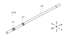
- FIG. 9A is a front perspective view of the stud bolt 195 and O-ring 21.
- the first O-ring 211 is shown as the first sealing member
- the second O-ring 212 is shown as the second sealing member.
- threads are formed at the front and rear ends of the stud bolt 195.
- an O-ring 21 serving as a seal member 20 is attached to the front end of the stud bolt 195.
- a first O-ring 211 and a second O-ring 212 are attached as the O-ring 21.
- the first O-ring 211 and the second O-ring 212 are made of synthetic resin or rubber molded into a ring shape, and function to prevent the ingress of the cooling fluid 23 described below.
- Figure 9B is an exploded perspective view showing the stud bolt 195 and O-ring 21 from the front.
- a first enlarged diameter portion 26 and a second enlarged diameter portion 27 are formed on the front end side of the stud bolt 195.
- the first enlarged diameter portion 26 and the second enlarged diameter portion 27 are portions of the stud bolt 195 that are partially raised radially outward.
- the first enlarged diameter portion 26 and the second enlarged diameter portion 27 are formed in a roughly ring shape around the stud bolt 195.
- the two first enlarged diameter sections 26 are formed close to each other.
- a first O-ring 211 is fitted between the first enlarged diameter sections 26.
- the second enlarged diameter portions 27 are formed close to each other.
- a second O-ring 212 is fitted between the second enlarged diameter portions 27.
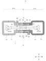
- FIG. 10 is a cross-sectional view showing a schematic configuration of the cooling passage 24, etc.
- the boundary 25 between the first engine block 111 and the second engine block 112 is shown by a dotted line.
- the engine block 11 has a first engine block 111, a second engine block 112, a third engine block 113 and a fourth engine block 114.
- the second cylinder chamber 122 is a space formed by joining the first engine block 111 and the second engine block 112. As described above, the third piston 161 and the fourth piston 171 reciprocate inside the second cylinder chamber 122 while the engine 10 is operating. Here, the third piston 161 and the fourth piston 171 reach their inner dead points, compressing the combustion chamber 34 formed inside the second cylinder chamber 122.
- the cooling flow passage 24 is a space formed near the cylinder chamber 12 and through which the cooling fluid 23 flows.
- the cooling flow passage 24 is configured to cool the first cylinder chamber 121 and the second cylinder chamber 122.
- a configuration in which the cooling flow passage 24 surrounds the second cylinder chamber 122 is illustrated.
- the first cylinder chamber 121 described above is also surrounded by the cooling flow passage 24.
- the cooling flow path 24 has a first cooling flow path 241, a second cooling flow path 242, and a connecting flow path 243.
- the first cooling passage 241 is a cavity formed in the thick portion of the first engine block 111.
- the first cooling passage 241 is formed so as to surround the front portion of the second cylinder chamber 122 from the periphery.
- the first cooling passage 241 is connected to the outside via the outlet portion 245.
- the second cooling passage 242 is a cavity formed in the thick portion of the second engine block 112.
- the second cooling passage 242 is formed so as to surround the rear portion of the second cylinder chamber 122.
- the second cooling passage 242 is connected to the outside via the inlet 244.
- connection flow path 243 is a space that communicates with the first cooling flow path 241 and the second cooling flow path 242 at the boundary 25.
- the cooling fluid 23 When the engine 10 is operating, the cooling fluid 23 is introduced from the inlet 244, flows through the second cooling passage 242, the connecting passage 243, and the first cooling passage 241, receives heat from the second cylinder chamber 122, and is taken out from the outlet 245.
- a fluid with a large specific heat such as water, can be used.
- a first cooling flow path 241, a second cooling flow path 242, and a connecting flow path 243 are formed so as to surround the second cylinder chamber 122 described above in the same manner as above.
- FIG. 11 is a cross-sectional view showing the configuration in which the stud bolt 195 penetrates the cooling passage 24. This cross-sectional view is taken along the line A-A shown in FIG. 1.
- a first cooling passage 241 is formed inside the first engine block 111, and a second cooling passage 242 is formed inside the second cylinder chamber 122, and the first cooling passage 241 and the second cooling passage 242 are connected by a connecting passage 243.
- the stud bolt 195 is arranged to pass through the first cooling passage 241, the second cooling passage 242, and the connecting passage 243.
- the front end of the stud bolt 195 is disposed inside the first fastening hole 285 of the first engine block 111.
- the middle portion of the stud bolt 195 is disposed in the second fastening hole 295 of the second cylinder chamber 122.
- the first fastening hole 285 and the second fastening hole 295 are in communication with the cooling flow passage 24.
- a gap is formed between the first fastening hole 285 and the second fastening hole 295 and the stud bolt 195. Therefore, unless any measures are taken, there is a risk that the cooling fluid 23 present inside the cooling flow passage 24 will leak to the outside through the gap.
- the aforementioned sealing member 20 prevents the cooling fluid 23 from leaking out.
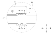
- the sealing member 20 is disposed on the stud bolt 195 in areas A and B shown in FIG. 11. This matter will be described later with reference to FIG. 12A and FIG. 12B.
- FIG. 12A is a cross-sectional view showing the relationship between the first fastening hole 285 and the stud bolt 195.
- FIG. 12A shows area A in FIG. 11.
- a first O-ring 211 is interposed in the gap between the stud bolt 195 and the first fastening hole 285.
- the first enlarged diameter portion 26 is formed in the stud bolt 195, and the first O-ring 211 is formed between the first enlarged diameter portions 26.
- the diameter of the first O-ring 211 in an uncompressed state is longer than the protruding height of the first enlarged diameter portion 26. Therefore, when the stud bolt 195 where the first O-ring 211 is arranged is inserted into the first fastening hole 285, the first O-ring 211 is compressed between the stud bolt 195 and the inner wall of the first fastening hole 285. This seals the gap between the stud bolt 195 and the first fastening hole 285.
- the first O-ring 211 prevents the cooling fluid 23 from entering between the stud bolt 195 and the first fastening hole 285 from the first cooling flow path 241. Additionally, the first fastening hole 285 is enlarged near the rear of the first engine block 111. The first enlarged portion 26 and the first O-ring 211 are disposed in the enlarged portion of the first fastening hole 285.
- FIG. 12B is a cross-sectional view showing the relationship between the second fastening hole 295 and the stud bolt 195.
- FIG. 12B shows area B in FIG. 11.
- a second O-ring 212 is interposed in the gap between the stud bolt 195 and the second engine block 112. As described above, the second enlarged diameter portion 27 is formed in the stud bolt 195, and the second O-ring 212 is formed between the second enlarged diameter portions 27. The diameter of the second O-ring 212 in an uncompressed state is longer than the protruding height of the second enlarged diameter portion 27. Therefore, when the stud bolt 195 in which the second O-ring 212 is arranged is inserted into the second fastening hole 295, the second O-ring 212 is compressed between the stud bolt 195 and the inner wall of the second fastening hole 295. This seals the gap between the stud bolt 195 and the second fastening hole 295.
- the second O-ring 212 prevents the cooling fluid 23 from entering between the stud bolt 195 and the second fastening hole 295 from the second cooling flow passage 242. Additionally, the second fastening hole 295 is enlarged near the front of the second engine block 112. The second enlarged portion 27 and the second O-ring 212 are disposed in the enlarged portion of the second fastening hole 295.
- FIG. 13A is a perspective view showing the stud bolt 195 and the cooling passage 24 from the rear.
- FIG. 13B is a perspective view showing the stud bolt 195 and the cooling passage 24 from the front.
- the first cooling passage 241, the second cooling passage 242, and a part of the connecting passage 243 are disposed between the first cylinder chamber 121 and the second cylinder chamber 122.
- the stud bolt 195 is disposed between the first cylinder chamber 121 and the second cylinder chamber 122 so as to penetrate the first cooling passage 241, the second cooling passage 242, and the connecting passage 243. In this manner, the cooling passage 24 also serves as an area for disposing the stud bolt 195. This allows the first cylinder chamber 121 and the second cylinder chamber 122 to be closer to each other, thereby realizing a more compact engine 10. As described above, the first O-ring 211 and the second O-ring 212 are attached to the stud bolt 195. Therefore, even if the stud bolt 195 is configured to penetrate the cooling passage 24, the cooling fluid 23 flowing through the cooling passage 24 is prevented from flowing out along the stud bolt 195 to the outside.
- the engine 10 described above has multiple cylinder chambers 12, but the number of cylinder chambers 12 can also be one.
Landscapes
- Engineering & Computer Science (AREA)
- Chemical & Material Sciences (AREA)
- Combustion & Propulsion (AREA)
- Mechanical Engineering (AREA)
- General Engineering & Computer Science (AREA)
- Cylinder Crankcases Of Internal Combustion Engines (AREA)
Priority Applications (2)
| Application Number | Priority Date | Filing Date | Title |
|---|---|---|---|
| JP2025538068A JPWO2025027731A1 (https=) | 2023-07-31 | 2023-07-31 | |
| PCT/JP2023/027904 WO2025027731A1 (ja) | 2023-07-31 | 2023-07-31 | エンジン |
Applications Claiming Priority (1)
| Application Number | Priority Date | Filing Date | Title |
|---|---|---|---|
| PCT/JP2023/027904 WO2025027731A1 (ja) | 2023-07-31 | 2023-07-31 | エンジン |
Publications (1)
| Publication Number | Publication Date |
|---|---|
| WO2025027731A1 true WO2025027731A1 (ja) | 2025-02-06 |
Family
ID=94394695
Family Applications (1)
| Application Number | Title | Priority Date | Filing Date |
|---|---|---|---|
| PCT/JP2023/027904 Pending WO2025027731A1 (ja) | 2023-07-31 | 2023-07-31 | エンジン |
Country Status (2)
| Country | Link |
|---|---|
| JP (1) | JPWO2025027731A1 (https=) |
| WO (1) | WO2025027731A1 (https=) |
Citations (9)
| Publication number | Priority date | Publication date | Assignee | Title |
|---|---|---|---|---|
| JPS4724187Y1 (https=) * | 1969-01-23 | 1972-08-01 | ||
| JPS5924949U (ja) * | 1982-08-09 | 1984-02-16 | 三井造船株式会社 | シリンダライナ |
| JPS606852U (ja) * | 1983-06-27 | 1985-01-18 | 日野自動車株式会社 | 直列型エンジン |
| JPH02238109A (ja) * | 1990-02-13 | 1990-09-20 | Yamaha Motor Co Ltd | 頭上カム軸式内燃機関 |
| JPH0465944U (https=) * | 1990-10-09 | 1992-06-09 | ||
| JPH0893498A (ja) * | 1994-09-26 | 1996-04-09 | Teruo Mikawa | 水平対向エンジン |
| JP2007046534A (ja) * | 2005-08-10 | 2007-02-22 | Kumikawa Tekkosho:Kk | 対向エンジン |
| JP5508604B2 (ja) * | 2011-09-30 | 2014-06-04 | 株式会社石川エナジーリサーチ | 対向ピストン型エンジン |
| JP2019183732A (ja) * | 2018-04-09 | 2019-10-24 | トヨタ自動車株式会社 | 対向ピストン内燃機関 |
-
2023
- 2023-07-31 WO PCT/JP2023/027904 patent/WO2025027731A1/ja active Pending
- 2023-07-31 JP JP2025538068A patent/JPWO2025027731A1/ja active Pending
Patent Citations (9)
| Publication number | Priority date | Publication date | Assignee | Title |
|---|---|---|---|---|
| JPS4724187Y1 (https=) * | 1969-01-23 | 1972-08-01 | ||
| JPS5924949U (ja) * | 1982-08-09 | 1984-02-16 | 三井造船株式会社 | シリンダライナ |
| JPS606852U (ja) * | 1983-06-27 | 1985-01-18 | 日野自動車株式会社 | 直列型エンジン |
| JPH02238109A (ja) * | 1990-02-13 | 1990-09-20 | Yamaha Motor Co Ltd | 頭上カム軸式内燃機関 |
| JPH0465944U (https=) * | 1990-10-09 | 1992-06-09 | ||
| JPH0893498A (ja) * | 1994-09-26 | 1996-04-09 | Teruo Mikawa | 水平対向エンジン |
| JP2007046534A (ja) * | 2005-08-10 | 2007-02-22 | Kumikawa Tekkosho:Kk | 対向エンジン |
| JP5508604B2 (ja) * | 2011-09-30 | 2014-06-04 | 株式会社石川エナジーリサーチ | 対向ピストン型エンジン |
| JP2019183732A (ja) * | 2018-04-09 | 2019-10-24 | トヨタ自動車株式会社 | 対向ピストン内燃機関 |
Also Published As
| Publication number | Publication date |
|---|---|
| JPWO2025027731A1 (https=) | 2025-02-06 |
Similar Documents
| Publication | Publication Date | Title |
|---|---|---|
| CN102753800B (zh) | 旋转式内燃机 | |
| JP6588532B2 (ja) | フリーピストンエンジン | |
| CN101225776A (zh) | 整体式汽缸曲柄轴箱 | |
| KR20070026088A (ko) | 스트로크 가변 엔진 | |
| JP2019011761A (ja) | 内燃機関 | |
| US7334558B2 (en) | Slide body internal combustion engine | |
| JP2007177774A (ja) | 2サイクルエンジン | |
| JP6754603B2 (ja) | 対向ピストン型エンジン | |
| US7086371B2 (en) | Engine | |
| WO2025027731A1 (ja) | エンジン | |
| CN110392772A (zh) | 内燃发动机 | |
| US5088285A (en) | Internal combustion engine | |
| KR101500409B1 (ko) | 엔진의 밸런스 샤프트 모듈 | |
| JP2009527678A (ja) | バレルエンジンブロック組立体 | |
| WO2025027735A1 (ja) | エンジン | |
| US5183014A (en) | Sleeve valve system for internal combustion engine having elliptical path | |
| JP2008516142A (ja) | 回転機械分野の組立体を有するvツイン構造 | |
| JPH09151783A (ja) | 多気筒エンジン | |
| WO2025027733A1 (ja) | エンジン | |
| KR102593671B1 (ko) | 대판 | |
| WO2025027734A1 (ja) | エンジン | |
| KR0153687B1 (ko) | 자동차용 크랭크 축 지지 구조 | |
| KR102478296B1 (ko) | 엔진용 오일 팬 어셈블리 | |
| WO2025027732A1 (ja) | エンジン | |
| JPH07109931A (ja) | 往復運動を回転運動に変換する装置および該装置を用いたレシプロエンジン |
Legal Events
| Date | Code | Title | Description |
|---|---|---|---|
| 121 | Ep: the epo has been informed by wipo that ep was designated in this application |
Ref document number: 23947530 Country of ref document: EP Kind code of ref document: A1 |
|
| ENP | Entry into the national phase |
Ref document number: 2025538068 Country of ref document: JP Kind code of ref document: A |
|
| WWE | Wipo information: entry into national phase |
Ref document number: 2025538068 Country of ref document: JP |
|
| NENP | Non-entry into the national phase |
Ref country code: DE |