WO2025023257A1 - 光ファイバテープ心線および光ファイバテープ心線の製造方法 - Google Patents
光ファイバテープ心線および光ファイバテープ心線の製造方法 Download PDFInfo
- Publication number
- WO2025023257A1 WO2025023257A1 PCT/JP2024/026362 JP2024026362W WO2025023257A1 WO 2025023257 A1 WO2025023257 A1 WO 2025023257A1 JP 2024026362 W JP2024026362 W JP 2024026362W WO 2025023257 A1 WO2025023257 A1 WO 2025023257A1
- Authority
- WO
- WIPO (PCT)
- Prior art keywords
- cores
- core
- fiber
- distance
- adjustment
- Prior art date
- Legal status (The legal status is an assumption and is not a legal conclusion. Google has not performed a legal analysis and makes no representation as to the accuracy of the status listed.)
- Pending
Links
Images


Classifications
-
- G—PHYSICS
- G02—OPTICS
- G02B—OPTICAL ELEMENTS, SYSTEMS OR APPARATUS
- G02B6/00—Light guides; Structural details of arrangements comprising light guides and other optical elements, e.g. couplings
- G02B6/02—Optical fibres with cladding with or without a coating
-
- G—PHYSICS
- G02—OPTICS
- G02B—OPTICAL ELEMENTS, SYSTEMS OR APPARATUS
- G02B6/00—Light guides; Structural details of arrangements comprising light guides and other optical elements, e.g. couplings
- G02B6/44—Mechanical structures for providing tensile strength and external protection for fibres, e.g. optical transmission cables
Definitions
- the present disclosure relates to an optical fiber ribbon and a method for manufacturing an optical fiber ribbon.
- This application claims priority based on Japanese Application No. 2023-120859 filed on July 25, 2023, and incorporates by reference all of the contents of said Japanese application.
- Patent Document 1 and Patent Document 2 disclose a ribbon core wire having multiple multi-core fibers and a manufacturing method thereof.
- Patent Document 3 discloses a method for aligning a multi-core fiber. In the alignment method described in Patent Document 3, illumination light is applied to the side of the multi-core fiber and the displacement of the shadow of the core is detected by an imaging device to detect the twist of the multi-core fiber, and the twist is eliminated using a twist elimination pulley.
- An optical fiber ribbon includes a plurality of multi-core fibers, each having a plurality of cores and a cladding covering the plurality of cores, and a coating member that at least partially coats the plurality of multi-core fibers.
- the plurality of cores is eight or more cores, and are arranged so as to be linearly symmetrical with respect to a reference line passing through the center of the fiber in a cross section of the at least one multi-core fiber.
- the distance between a pair of adjustment cores that are located on the reference line and are furthest from each other is greater than the maximum radius, which is the distance between the fiber center and the outermost core that is furthest from the fiber center.
- FIG. 1 is a cross-sectional view showing an optical fiber ribbon according to an embodiment.
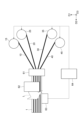
- FIG. 2 is a diagram showing a method for manufacturing the optical fiber ribbon shown in FIG.
- FIG. 3 is a diagram for explaining a method of aligning cores in a multicore fiber.
- Parts (a), (b) and (c) of FIG. 4 are diagrams showing the measurement results of symmetry in the core alignment shown in FIG.
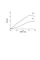
- FIG. 5 is a diagram showing an example of the relationship between asymmetry and the rotation angle.
- FIG. 6 is a schematic diagram for explaining the inter-core distance dc and the core movement amount in a multi-core fiber. Part (a) of FIG.
- FIG. 7 shows a typical core arrangement in a 12-core multi-core fiber, and parts (b) and (c) show core arrangements in which the inter-core distance in a 12-core multi-core fiber is increased.
- Part (a) of Figure 8 shows a typical core arrangement in a 16-core multi-core fiber, and parts (b), (c), (d), and (e) show core arrangements in which the inter-core distance in a 16-core multi-core fiber is increased and the cores are positioned in rotationally asymmetric positions.
- Parts (a) and (b) of FIG. 9 show a modified core arrangement in which the inter-core distance in a 12-core multi-core fiber is increased, and parts (c) and (d) of FIG.
- An optical fiber ribbon includes a plurality of multi-core fibers, each having a plurality of cores and a cladding covering the plurality of cores, and a coating member that at least partially coats the plurality of multi-core fibers.
- the plurality of cores are eight or more cores, and are arranged to be linearly symmetrical with respect to a reference line passing through a fiber center in a cross section of the at least one multi-core fiber.
- a distance between a pair of adjustment cores that are located on the reference line and are furthest from each other among the plurality of cores is greater than a maximum radius that is a distance between the fiber center and the outermost core that is furthest from the fiber center.
- the distance between a pair of adjustment cores that are located on the reference line and are farthest from each other among the multiple cores is greater than the maximum radius, which is the distance between the fiber center and the outermost core among the multiple cores that is farthest from the fiber center in the radial direction.
- the maximum radius which is the distance between the fiber center and the outermost core among the multiple cores that is farthest from the fiber center in the radial direction.
- At least one of the pair of adjustment cores may be arranged on a circumference centered on the center of the fiber, on which the outermost core is arranged.
- the distance between the pair of adjustment cores can be made longer, making it easier to adjust the asymmetry even with a large number of cores. Therefore, with this optical fiber ribbon core wire, the core position can be detected with even greater accuracy.
- the multiple cores may be arranged so that they are rotationally asymmetric when rotated at an angle of 360/n degrees (n is any integer equal to or greater than 2) around the center of the fiber.
- n is any integer equal to or greater than 2
- the rotation direction for core alignment can be easily determined and alignment can be performed.
- the number of cores may be 12.
- the number of cores may be 16.
- a method for manufacturing an optical fiber ribbon includes the steps of preparing a plurality of multi-core fibers, each having a plurality of cores and a cladding covering the plurality of cores, coating each of the plurality of multi-core fibers with resin while arranging the plurality of multi-core fibers in parallel with each other, and irradiating light onto a light irradiation surface of a coating resin portion that coats at least one of the plurality of multi-core fibers, and aligning the arrangement of the plurality of cores in the at least one multi-core fiber based on the result of the light irradiation.
- the plurality of cores are eight or more cores, and are arranged to be linearly symmetrical with respect to a reference line passing through the center of the fiber in the cross section of the at least one multi-core fiber.
- the distance between a pair of adjustment cores that are located on the reference line and are farthest from each other among the plurality of cores is greater than the maximum radius, which is the distance between the fiber center and the outermost core farthest from the fiber center.
- At least one multi-core fiber is arranged so that the reference line of at least one multi-core fiber intersects with the light irradiation surface, light is irradiated onto the light irradiation surface in the coating resin portion, and the multiple cores of at least one multi-core fiber are aligned using the image transmitted through a pair of adjustment cores.
- the multiple cores are eight or more cores, and are arranged so as to be linearly symmetrical with respect to a reference line passing through the center of the fiber in the cross section of the multicore fiber.
- the distance between a pair of adjustment cores located on the reference line and furthest from each other among the multiple cores is greater than the maximum radius, which is the distance between the fiber center and the outermost core among the multiple cores that is furthest from the fiber center in the radial direction.
- the multi-core fiber 10 has a plurality of cores 11, a clad 12 covering the plurality of cores 11, a primary resin layer 13 covering the clad 12, and a secondary resin layer 14 covering the primary resin layer 13.
- 12 cores 11 are arranged in line symmetry, with eight cores evenly spaced on the outer circumference and four cores evenly spaced on the inner circumference.
- the line serving as the reference for line symmetry here is the observation axis when inspecting the core arrangement by rotating the multi-core fiber when producing the optical fiber ribbon 1, and is, for example, a line that intersects at right angles (intersects) with the light irradiation surface 51a of the coating member 50 and passes through the fiber center of the multi-core fiber 10.
- the core 11 is made of pure silica (SiO 2 ) glass or a material in which germanium dioxide or fluorine is added to silica glass.
- the cladding 12 has a refractive index lower than that of the core 11.
- the cladding 12 is made of, for example, pure silica glass or a material in which fluorine is added to silica glass.
- a trench having a refractive index lower than that of the cladding 12 may be provided between each core 11 and the cladding 12.
- the primary resin layer 13 coats the outer periphery of the clad 12. More specifically, the primary resin layer 13 is in contact with the outer peripheral surface of the clad 12, and coats the entire clad 12.
- the secondary resin layer 14 further coats the outer periphery of the primary resin layer 13. More specifically, the secondary resin layer 14 is in contact with the outer peripheral surface of the primary resin layer 13, and coats the entire primary resin layer 13.
- the primary resin layer 13 can be formed by curing an ultraviolet-curable resin composition containing a photopolymerizable compound, a photopolymerization initiator, and a silane coupling agent.
- urethane (meth)acrylate or epoxy (meth)acrylate can be used as the photopolymerizable compound.
- the secondary resin layer 14 can be formed by curing a resin composition containing urethane (meth)acrylate, a monomer, and a photopolymerization initiator.
- the secondary resin layer 14 has a higher elasticity than the primary resin layer 13, and the secondary resin layer 14 is harder than the primary resin layer 13.
- the thickness of each layer of the primary resin layer 13 and the secondary resin layer 14 is, for example, 5 ⁇ m or more and 50 ⁇ m or less.
- the multi-core fiber 20, like the multi-core fiber 10, has multiple cores 21, a clad 22 covering the multiple cores 21, a primary resin layer 23 covering the clad 22, and a secondary resin layer 24 covering the primary resin layer 23.
- the multi-core fiber 30, like the multi-core fiber 10, has multiple cores 31, a clad 32 covering the multiple cores 31, a primary resin layer 33 covering the clad 32, and a secondary resin layer 34 covering the primary resin layer 33.
- the multi-core fiber 40, like the multi-core fiber 10, has multiple cores 41, a clad 42 covering the multiple cores 41, a primary resin layer 43 covering the clad 42, and a secondary resin layer 44 covering the primary resin layer 43.
- the coating portions 51 to 54 are in contact with the outer circumferential surfaces of the corresponding multicore fibers (the outer circumferential surfaces of the secondary resin layers, and the outer circumferential surfaces of the colored inks, if any) and cover the entirety of each multicore fiber.
- Coated portion 51 has a shape that generally corresponds to the outer peripheral shape of the coated multi-core fiber 10, and has, for example, a substantially circular cross-sectional shape.
- coated portion 52, coated portion 53, and coated portion 54 have shapes that generally correspond to the outer peripheral shapes of the coated multi-core fiber 20, multi-core fiber 30, and multi-core fiber 40, respectively, and have, for example, a substantially circular cross-sectional shape.
- the coated portion 51, the coated portion 52, the coated portion 53, and the coated portion 54 are formed with light irradiation surfaces 51a, 52a, 53a, and 54a, which are flat surfaces.
- the light irradiation surfaces 51a to 54a may not be flat surfaces, but may be curved surfaces.
- the light irradiation surface 51a is provided in a region where a reference line (center line) passing through the fiber center and two or more cores 11 intersects with the outer periphery of the coated portion 51. In other words, the light irradiation surface 51a is provided on one side of the third direction D3 (upward in the figure) with respect to the core 11.
- the light irradiation surfaces 52a to 54a are provided in a region where a reference line (center line) passing through each fiber center and two or more cores 21, 31, and 41 intersects with the outer periphery of the coated portion 52, the coated portion 53, and the coated portion 54, respectively, similar to the light irradiation surface 51a.
- FIG. 2 is a schematic diagram showing a method for manufacturing the optical fiber ribbon 1 shown in FIG. 1.
- the multi-core fibers 10, 20, 30, 40 thus drawn out from the supply rolls 15, 25, 35, 45 are arranged in parallel to one another along the second direction D2 in the die 61 and are coated with resin.
- This resin is a ribbon resin that forms the coating member 50, and contains a thermosetting resin such as silicone resin, epoxy resin, or urethane resin, or an ultraviolet-curing resin such as epoxy acrylate, urethane acrylate, or polyester acrylate.
- a resin is introduced into the die 61, and the ribbon resin is applied to cover the multi-core fibers 10 to 40 aligned within the die 61. The applied resin is then irradiated with ultraviolet light (not shown) to harden the ribbon resin.
- the multiple cores in each multicore fiber 10, 20, 30, 40 are aligned.
- the brightness data from the light receiving device 63 is analyzed by the control device 64, and the angles of the supply rolls 15, 25, 35, 45 are fine-tuned by a motor (not shown) or the like so that the brightness data has symmetry based on the analysis results. This adjusts the positions of the cores.
- the illumination light is irradiated from the light irradiation surfaces 51a, 52a, 53a, and 54a provided corresponding to each of the multi-core fibers 10, 20, 30, and 40 to irradiate the inside of the multi-core fiber, and the multi-core fiber is rotated and aligned until each of the transmitted lights has a symmetrical shape (for example, the shape in FIG. 4(b)).
- a symmetrical shape for example, the shape in FIG. 4(b)
- Fig. 3 is a diagram for explaining core alignment of a multi-core fiber.
- Parts (a), (b), and (c) of Fig. 4 are diagrams showing the measurement results of symmetry in the core alignment shown in Fig. 3, and show the cases where the alignment angles are -1 deg, ⁇ 0 deg, and +1 deg, respectively.
- the multi-core fiber has multiple cores 11, a cladding 12 covering the cores 11, a primary resin layer 13, and a secondary resin layer 14.
- Illumination light L is irradiated to the side of such a multi-core fiber 10, and the transmitted light is received by a camera, which is a light receiving device, to perform observation.
- a graph of the brightness data received by such a camera is, for example, as shown in parts (a) to (c) of Fig. 4. Then, to make the graph of this brightness data symmetrical as shown in part (b) of Figure 4, the multicore fiber 10 is slightly rotated in the plus (+) or minus (-) direction shown in Figure 3 to perform alignment.
- Figure 5 shows a graph that represents the symmetry of such brightness data in relation to the rotation angle.
- the graph in Figure 5 shows the relationship between the asymmetry and the rotation angle when the maximum distance dc (see Figure 6) between the cores to be aligned is changed.
- dc1 is a graph when the inter-core distance dc is 40 ⁇ m
- dc2 is a graph when the inter-core distance dc is 80 ⁇ m.
- dc2 which has a wider inter-core distance, allows greater adjustment of asymmetry and makes it easier to adjust the core position as the rotation angle increases.
- Figure 6 explains the amount of core movement and inter-core distance dc when a multi-core fiber is rotated.
- FIG. 7 shows a typical core arrangement in a 12-core multicore fiber, and parts (b) and (c) show core arrangements in which the inter-core distance in a 12-core multicore fiber is increased.
- the black circles shown in parts (a) to (c) of FIG. 7 indicate cores in the multicore fiber.
- 12 cores 11 are arranged so as to be linearly symmetric (bilaterally symmetric) with respect to the observation axis G that is perpendicular to the light irradiation surface 51a and passes through the fiber center C of the multicore fiber.
- the number of adjustment cores 11a arranged on the observation axis G is two, and the distance dc between a pair of adjustment cores 11a is smaller than the maximum radius r, which is the distance between the fiber center C and the outermost core 11b, which is the most distant from the fiber center C in the radial direction among the multiple cores 11.
- the maximum radius r is 1.58, while the inter-core distance dc is 1.41.
- the distance dc between the adjustment cores 11a is shorter than the maximum radius r, it is not necessarily easy to eliminate the asymmetry.
- 12 cores 11 are arranged so as to be symmetrical (symmetrical) with respect to the observation axis G (reference line) that is perpendicular to the light irradiation surface 51a and passes through the fiber center C of the multicore fiber 10.
- the number of adjustment cores 11a arranged on the observation axis G is four, and a pair of adjustment cores 11a among them are arranged at the outer periphery S.
- the distance dc between the pair of adjustment cores 11a located on the outermost side is larger than the maximum radius r, which is the distance between the fiber center C and the outermost core 11b among the multiple cores 11 that is the farthest from the fiber center C in the radial direction.
- the maximum radius r is 1.71
- the inter-core distance dc is 3.41.
- the distance dc between the adjustment cores 11a is longer than the maximum radius r, so it is easy to eliminate asymmetry and alignment can be performed with precision.
- 12 cores 11 are arranged so as to be linearly symmetric (bilaterally symmetric) with respect to the observation axis G that is perpendicular to the light irradiation surface 51a and passes through the fiber center C of the multicore fiber 10.
- the number of adjustment cores 11a arranged on the observation axis G is two, and one of the pair of adjustment cores 11a is arranged on the outer periphery S and the other is arranged inside the outer periphery S.
- the distance dc between the pair of adjustment cores 11a is larger than the maximum radius r, which is the distance between the fiber center C and the outermost core 11b of the multiple cores 11 that is the farthest from the fiber center C in the radial direction.
- the maximum radius r is 1.53
- the inter-core distance dc is 1.73.
- the multiple cores 11 are arranged so that they are rotationally asymmetric. In this case, the rotation direction for alignment can be easily determined.
- FIG. 8 shows a typical core arrangement in a 16-core multicore fiber
- parts (b), (c), (d), and (e) show core arrangements in which the inter-core distance is increased in a 16-core multicore fiber.
- the black circles shown in parts (a) to (e) of FIG. 8 indicate cores in the multicore fiber.
- 16 cores 11 are arranged so as to be linearly symmetrical (bilaterally symmetrical) with respect to the observation axis G that is perpendicular to the light irradiation surface 51a and passes through the fiber center C of the multicore fiber.
- the number of adjustment cores 11a arranged on the observation axis G is four, and the distance dc between the pair of adjustment cores 11a located on the outermost side is greater than the maximum radius r, which is the distance between the fiber center C and the outermost core 11b, which is the most distant from the fiber center C in the radial direction among the multiple cores 11.
- the cores 11 are arranged so as to be rotationally symmetrical. In this case, it may not be easy to determine the rotation direction for alignment.
- 16 cores 11 are arranged so as to be linearly symmetrical (bilaterally symmetrical) with respect to the observation axis G that is perpendicular to the light irradiation surface 51a and passes through the fiber center C of the multicore fiber 10.
- the number of adjustment cores 11a arranged on the observation axis G is four, and one of the other cores 11c arranged on the observation axis G is moved from the arrangement structure shown in FIG. 8A to the outside in the radial direction (upward in the figure) on the observation axis G while the pair of adjustment cores 11a located on the outer periphery S are arranged.
- the cores 11 are arranged so as to be rotationally asymmetric.
- the rotation direction for alignment can be easily determined.
- the minimum distance between cores (core pitch) is 1, the maximum radius r is 1.93, while the inter-core distance dc is 3.86, so that the asymmetry can be easily eliminated and alignment can be performed with high accuracy.
- 16 cores 11 are arranged so as to be linearly symmetric (bilaterally symmetric) with respect to the observation axis G that is perpendicular to the light irradiation surface 51a and passes through the fiber center C of the multicore fiber 10.
- the number of adjustment cores 11a arranged on the observation axis G is two, and while a pair of adjustment cores 11a are arranged on the outer periphery S, the four cores 11d located on the inside are arranged above the multicore fiber.
- the cores 11 are arranged so as to be rotationally asymmetric.
- the rotation direction for alignment can be easily determined.
- the minimum distance between cores (core pitch) is 1
- the maximum radius r is 1.93
- the inter-core distance dc is 3.86, so that it is easy to eliminate the asymmetry and alignment can be performed with high accuracy.
- 16 cores 11 are arranged so as to be linearly symmetric (bilaterally symmetric) with respect to the observation axis G that is perpendicular to the light irradiation surface 51a and passes through the fiber center C of the multicore fiber 10.
- the number of adjustment cores 11a arranged on the observation axis G is two, and the first adjustment core of the pair of adjustment cores 11a is arranged on the outer periphery S, the second adjustment core is arranged within the outer periphery S, and the five cores 11e (including the second adjustment core 11a) located on the inside are arranged to form a pentagonal shape.
- the cores 11 are arranged so as to be rotationally asymmetric.
- the rotation direction for alignment can be easily determined.
- the minimum distance between cores (core pitch) is 1
- the maximum radius r1 is 1.81
- the inter-core distance dc is 2.71, so that the asymmetry can be easily eliminated and alignment can be performed with high accuracy.
- 16 cores 11 are arranged so as to be linearly symmetric (bilaterally symmetric) with respect to the observation axis G that is perpendicular to the light irradiation surface 51a and passes through the fiber center C of the multicore fiber 10.
- the number of adjustment cores 11a arranged on the observation axis G is four, and among them, a pair of adjustment cores 11a located on the outer periphery S is arranged, and two more cores 11f are arranged on the observation axis G, and the five cores 11e located on the inside (one core 11f is shared) are arranged to form a pentagonal shape.
- the cores 11 are arranged so as to be rotationally asymmetric.
- the rotation direction for alignment can be easily determined.
- the minimum distance between the cores is 1, the maximum radius r1 is 2.00, while the inter-core distance dc is 4.00, so that it is easy to eliminate the asymmetry and alignment can be performed with high accuracy.
- the multicore fiber 10 will be used as an example, but the same applies to the multicore fibers 20, 30, and 40.
- Parts (a) and (b) of FIG. 9 show a modified core arrangement in which the inter-core distance is increased in a 12-core multicore fiber
- parts (c) and (d) of FIG. 9 show a modified core arrangement in which the inter-core distance is increased in a 16-core multicore fiber.
- the number of adjustment cores 11a arranged on the observation axis G that is perpendicular to the light irradiation surface 51a and passes through the fiber center C of the multicore fiber 10 is four, and the first adjustment core of the pair of adjustment cores 11a located on the outermost side is arranged at the position of the outer periphery S, and the second adjustment core is located slightly inside the outer periphery S.
- Each core 11 is arranged by shifting a part of the cores arranged in a square.
- the distance dc between the pair of adjustment cores 11a is larger than the maximum radius r, which is the distance between the fiber center C and the outermost core 11b of the multiple cores 11 that is the farthest from the fiber center C in the radial direction.
- the maximum radius r is 1.80
- the inter-core distance dc is 3.30.
- the multiple cores 11 are arranged so that they are rotationally asymmetric. In this case, the rotation direction for alignment can be easily determined.
- the number of adjustment cores 11a arranged on the observation axis G that is perpendicular to the light irradiation surface 51a and passes through the fiber center C of the multicore fiber 10 is four, and both of the pair of adjustment cores 11a located on the outermost side are arranged at the outer periphery S.
- Each core 11 is arranged by thinning out some of the cores arranged in a square.
- the distance dc between the pair of adjustment cores 11a is larger than the maximum radius r, which is the distance between the fiber center C and the outermost core 11b among the multiple cores 11 that is the farthest from the fiber center C in the radial direction.
- the multiple cores 11 are arranged so that they are rotationally asymmetric. In this case, the rotation direction for alignment can be easily determined.
- the number of adjustment cores 11a arranged on the observation axis G that is perpendicular to the light irradiation surface 51a and passes through the fiber center C of the multicore fiber 10 is four, and both of the pair of adjustment cores 11a located on the outermost side are arranged at the outer periphery S.
- the distance dc between the pair of adjustment cores 11a is larger than the maximum radius r, which is the distance between the fiber center C and the outermost core 11b of the multiple cores 11 that is the farthest from the fiber center C in the radial direction.
- the multiple cores 11 are arranged so as to be rotationally asymmetric. In this case, the rotation direction for alignment can be easily determined.
- the number of adjustment cores 11a arranged on the observation axis G that is perpendicular to the light irradiation surface 51a and passes through the fiber center C of the multicore fiber 10 is four, and the first adjustment core of the pair of adjustment cores 11a located on the outermost side is arranged at the position of the outer periphery S, and the second adjustment core is located slightly inside the outer periphery S.
- the distance dc between the pair of adjustment cores 11a is larger than the maximum radius r, which is the distance between the fiber center C and the outermost core 11b of the multiple cores 11 that is the farthest from the fiber center C in the radial direction.
- the multiple cores 11 are arranged so that they are rotationally asymmetric. In this case, the direction of rotation for alignment can be easily determined.
- FIG. 10 a further example of an arrangement of multiple cores including a pair of adjustment cores that are irradiated with light will be described.
- the multicore fiber 10 will be used as an example, but the same applies to the multicore fibers 20, 30, and 40.
- Part (a) of FIG. 10 shows a typical core arrangement in an eight-core multicore fiber
- part (b) of FIG. 10 shows a core arrangement in an eight-core multicore fiber in which the inter-core distance is increased and the cores are positioned in a rotationally asymmetric manner.
- eight cores 11 are arranged so as to be linearly symmetric (bilaterally symmetric) with respect to the observation axis G that is perpendicular to the light irradiation surface 51a and passes through the fiber center C of the multicore fiber.
- the number of adjustment cores 11a arranged on the observation axis G is two, and the distance dc between a pair of adjustment cores 11a is the same as the maximum radius r, which is the distance between the fiber center C and the outermost core 11b, which is the most distant from the fiber center C in the radial direction among the multiple cores 11.
- the maximum radius r is 1.15
- the inter-core distance dc is 1.15.
- the distance dc between the adjustment cores 11a is the same as the maximum radius r, it is not necessarily easy to eliminate the asymmetry.
- eight cores 11 are arranged so as to be symmetrical (symmetrical) with respect to the observation axis G (reference line) that is perpendicular to the light irradiation surface 51a and passes through the fiber center C of the multicore fiber 10.
- the number of adjustment cores 11a arranged on the observation axis G is two, and the first adjustment core 11a is arranged at the position of the outer periphery S, while the second adjustment core 11a is moved in a direction away from the center C (downward in the figure).
- the distance dc between a pair of adjustment cores 11a is larger than the maximum radius r, which is the distance between the fiber center C and the outermost core 11b among the multiple cores 11 that is the farthest from the fiber center C in the radial direction.
- the maximum radius r is 1.15
- the inter-core distance dc is 1.33.
- the cores 11 are arranged so that they are rotationally asymmetric. In this case, the rotation direction for alignment can be easily determined.
- the distance dc between a pair of adjustment cores 11a that are located on the observation axis G, which is a reference line, and are farthest from each other among the multiple cores 11, is greater than the maximum radius r, which is the distance between the fiber center C and the outermost core 11b, which is the most distant from the fiber center C in the radial direction among the multiple cores 11.
- the maximum radius r which is the distance between the fiber center C and the outermost core 11b, which is the most distant from the fiber center C in the radial direction among the multiple cores 11.
- the multiple cores 11 may be arranged so that they are rotationally asymmetric when rotated around the fiber center at an angle of 360/n degrees (n is any integer equal to or greater than 2) (e.g., 180 degrees, 120 degrees, 90 degrees, 72 degrees, 51.43 degrees).
- n is any integer equal to or greater than 2
- the rotation direction for core alignment can be easily determined and alignment can be performed.
- optical fiber ribbon and its manufacturing method according to the present disclosure have been described in detail above, but the present invention is not limited to the above embodiment and can be applied to various embodiments and modified examples.
- the above description has been about an optical fiber ribbon including four multicore fibers, but the present disclosure is not limited to this.
- the contents of the present disclosure may be applied to an optical fiber ribbon including two multicore fibers.
Landscapes
- Physics & Mathematics (AREA)
- General Physics & Mathematics (AREA)
- Optics & Photonics (AREA)
- Optical Couplings Of Light Guides (AREA)
Priority Applications (1)
| Application Number | Priority Date | Filing Date | Title |
|---|---|---|---|
| JP2025535843A JPWO2025023257A1 (https=) | 2023-07-25 | 2024-07-23 |
Applications Claiming Priority (2)
| Application Number | Priority Date | Filing Date | Title |
|---|---|---|---|
| JP2023-120859 | 2023-07-25 | ||
| JP2023120859 | 2023-07-25 |
Publications (1)
| Publication Number | Publication Date |
|---|---|
| WO2025023257A1 true WO2025023257A1 (ja) | 2025-01-30 |
Family
ID=94374584
Family Applications (1)
| Application Number | Title | Priority Date | Filing Date |
|---|---|---|---|
| PCT/JP2024/026362 Pending WO2025023257A1 (ja) | 2023-07-25 | 2024-07-23 | 光ファイバテープ心線および光ファイバテープ心線の製造方法 |
Country Status (2)
| Country | Link |
|---|---|
| JP (1) | JPWO2025023257A1 (https=) |
| WO (1) | WO2025023257A1 (https=) |
Citations (12)
| Publication number | Priority date | Publication date | Assignee | Title |
|---|---|---|---|---|
| JP2013167861A (ja) * | 2012-01-19 | 2013-08-29 | Fujikura Ltd | マルチコアファイバ |
| JP2014052560A (ja) * | 2012-09-07 | 2014-03-20 | Nippon Telegr & Teleph Corp <Ntt> | 光伝送媒体、光伝送システム、及び光伝送方法 |
| JP2014133673A (ja) | 2013-01-09 | 2014-07-24 | Hitachi Metals Ltd | ファイバ素線製造装置及びテープ心線 |
| WO2016027896A1 (ja) * | 2014-08-22 | 2016-02-25 | 住友電気工業株式会社 | 光ファイバ |
| WO2016047658A1 (ja) | 2014-09-24 | 2016-03-31 | 古河電気工業株式会社 | テープ心線およびテープ心線の製造方法 |
| JP2017173514A (ja) | 2016-03-23 | 2017-09-28 | 古河電気工業株式会社 | 光ファイバテープ心線および光ファイバテープ心線の製造方法 |
| JP2018198287A (ja) * | 2017-05-24 | 2018-12-13 | 日本電信電話株式会社 | 増幅用ファイバ |
| JP2020098350A (ja) * | 2014-10-22 | 2020-06-25 | 住友電気工業株式会社 | 光コネクタ |
| JP2021131493A (ja) * | 2020-02-20 | 2021-09-09 | 株式会社フジクラ | マルチコアファイバ、光ファイバケーブル、及び光ファイバコネクタ |
| WO2022254986A1 (ja) * | 2021-06-04 | 2022-12-08 | 住友電気工業株式会社 | 光ファイバの製造方法、光ファイバ、光ファイバリボンの製造方法、光ファイバリボン、光ファイバの製造装置、及び、光ファイバリボンの製造装置 |
| JP2023120859A (ja) | 2022-02-18 | 2023-08-30 | Idec株式会社 | 牛乳受け箱 |
| US20240004136A1 (en) * | 2020-12-08 | 2024-01-04 | Ofs Fitel, Llc | Methods and apparatus for aligning and splicing optical fibers |
-
2024
- 2024-07-23 JP JP2025535843A patent/JPWO2025023257A1/ja active Pending
- 2024-07-23 WO PCT/JP2024/026362 patent/WO2025023257A1/ja active Pending
Patent Citations (12)
| Publication number | Priority date | Publication date | Assignee | Title |
|---|---|---|---|---|
| JP2013167861A (ja) * | 2012-01-19 | 2013-08-29 | Fujikura Ltd | マルチコアファイバ |
| JP2014052560A (ja) * | 2012-09-07 | 2014-03-20 | Nippon Telegr & Teleph Corp <Ntt> | 光伝送媒体、光伝送システム、及び光伝送方法 |
| JP2014133673A (ja) | 2013-01-09 | 2014-07-24 | Hitachi Metals Ltd | ファイバ素線製造装置及びテープ心線 |
| WO2016027896A1 (ja) * | 2014-08-22 | 2016-02-25 | 住友電気工業株式会社 | 光ファイバ |
| WO2016047658A1 (ja) | 2014-09-24 | 2016-03-31 | 古河電気工業株式会社 | テープ心線およびテープ心線の製造方法 |
| JP2020098350A (ja) * | 2014-10-22 | 2020-06-25 | 住友電気工業株式会社 | 光コネクタ |
| JP2017173514A (ja) | 2016-03-23 | 2017-09-28 | 古河電気工業株式会社 | 光ファイバテープ心線および光ファイバテープ心線の製造方法 |
| JP2018198287A (ja) * | 2017-05-24 | 2018-12-13 | 日本電信電話株式会社 | 増幅用ファイバ |
| JP2021131493A (ja) * | 2020-02-20 | 2021-09-09 | 株式会社フジクラ | マルチコアファイバ、光ファイバケーブル、及び光ファイバコネクタ |
| US20240004136A1 (en) * | 2020-12-08 | 2024-01-04 | Ofs Fitel, Llc | Methods and apparatus for aligning and splicing optical fibers |
| WO2022254986A1 (ja) * | 2021-06-04 | 2022-12-08 | 住友電気工業株式会社 | 光ファイバの製造方法、光ファイバ、光ファイバリボンの製造方法、光ファイバリボン、光ファイバの製造装置、及び、光ファイバリボンの製造装置 |
| JP2023120859A (ja) | 2022-02-18 | 2023-08-30 | Idec株式会社 | 牛乳受け箱 |
Also Published As
| Publication number | Publication date |
|---|---|
| JPWO2025023257A1 (https=) | 2025-01-30 |
Similar Documents
| Publication | Publication Date | Title |
|---|---|---|
| CN105229510B (zh) | 光纤带芯线及光缆 | |
| US9958604B2 (en) | Optical fiber, and optical-fiber production method | |
| CN105899981A (zh) | 多芯光纤及其制造方法 | |
| US8452146B2 (en) | Process for manufacturing an optical fiber and an optical fiber so obtained | |
| JP2006522953A (ja) | 優先的分離順序を有する光ファイバリボン | |
| CN114008503B (zh) | 间歇连结型光纤带、及间歇连结型光纤带的制造方法 | |
| JP7312671B2 (ja) | 光ファイバテープ心線の製造方法及び光ファイバテープ心線 | |
| US20170299830A1 (en) | Optical Fiber Ribbon, and Optical-Fiber-Ribbon Production Method | |
| US20150016791A1 (en) | Multi-core optical fiber tape | |
| EP2056147B1 (en) | Optical fiber ribbon | |
| US12222541B2 (en) | Optical fiber bundle structure, optical connector, optical fiber connection structure, and method of manufacturing optical fiber bundle structure | |
| US9835812B2 (en) | Multi-optical fiber aggregate | |
| WO2023182224A1 (ja) | ファイバ融着接続装置およびファイバ融着接続方法 | |
| JP7297643B2 (ja) | 光ファイバテープ心線の製造方法及び光ファイバテープ心線の製造装置 | |
| WO2025023257A1 (ja) | 光ファイバテープ心線および光ファイバテープ心線の製造方法 | |
| JP2020003620A (ja) | 間欠連結型光ファイバテープ、及び間欠連結型光ファイバテープの製造方法 | |
| US20250224554A1 (en) | Optical fiber, optical fiber ribbon, and method of manufacturing optical fiber | |
| WO2025023306A1 (ja) | 光ファイバテープ心線および光ファイバテープ心線の製造方法 | |
| JP7778248B2 (ja) | マルチコア光ファイバの調心装置、マルチコア光ファイバリボンの製造装置、マルチコア光ファイバユニットの製造装置、マルチコア光ファイバの調心方法、マルチコア光ファイバリボンの製造方法、マルチコア光ファイバユニットの製造方法、マルチコア光ファイバリボンの検査装置、及びマルチコア光ファイバリボンの検査方法 | |
| JP2025123678A (ja) | テープファイバおよびテープファイバの製造方法 | |
| WO2025263438A1 (ja) | 光ファイバ、光ファイバ平型素線、光ファイバテープ心線、および、光ファイバテープ心線の製造方法 | |
| US20250314817A1 (en) | Optical fibers with non-circular coating | |
| WO2025173711A1 (ja) | 光ファイバ、光ファイバの製造方法、テープファイバ、および、テープファイバの製造方法 | |
| US20240255705A1 (en) | Method for manufacturing optical fiber bundle, optical fiber bundle, optical connection structure, and determination method | |
| JPWO2025023306A5 (https=) |
Legal Events
| Date | Code | Title | Description |
|---|---|---|---|
| 121 | Ep: the epo has been informed by wipo that ep was designated in this application |
Ref document number: 24845632 Country of ref document: EP Kind code of ref document: A1 |
|
| ENP | Entry into the national phase |
Ref document number: 2025535843 Country of ref document: JP Kind code of ref document: A |
|
| WWE | Wipo information: entry into national phase |
Ref document number: 2025535843 Country of ref document: JP |
|
| WWE | Wipo information: entry into national phase |
Ref document number: 2024845632 Country of ref document: EP |
|
| NENP | Non-entry into the national phase |
Ref country code: DE |