WO2025022840A1 - 成形装置、成形システム、及び金属パイプ - Google Patents
成形装置、成形システム、及び金属パイプ Download PDFInfo
- Publication number
- WO2025022840A1 WO2025022840A1 PCT/JP2024/020915 JP2024020915W WO2025022840A1 WO 2025022840 A1 WO2025022840 A1 WO 2025022840A1 JP 2024020915 W JP2024020915 W JP 2024020915W WO 2025022840 A1 WO2025022840 A1 WO 2025022840A1
- Authority
- WO
- WIPO (PCT)
- Prior art keywords
- metal pipe
- quenching
- die
- molding
- pipe material
- Prior art date
- Legal status (The legal status is an assumption and is not a legal conclusion. Google has not performed a legal analysis and makes no representation as to the accuracy of the status listed.)
- Pending
Links
Images




Classifications
-
- B—PERFORMING OPERATIONS; TRANSPORTING
- B21—MECHANICAL METAL-WORKING WITHOUT ESSENTIALLY REMOVING MATERIAL; PUNCHING METAL
- B21D—WORKING OR PROCESSING OF SHEET METAL OR METAL TUBES, RODS OR PROFILES WITHOUT ESSENTIALLY REMOVING MATERIAL; PUNCHING METAL
- B21D22/00—Shaping without cutting, by stamping, spinning, or deep-drawing
- B21D22/20—Deep-drawing
-
- B—PERFORMING OPERATIONS; TRANSPORTING
- B21—MECHANICAL METAL-WORKING WITHOUT ESSENTIALLY REMOVING MATERIAL; PUNCHING METAL
- B21D—WORKING OR PROCESSING OF SHEET METAL OR METAL TUBES, RODS OR PROFILES WITHOUT ESSENTIALLY REMOVING MATERIAL; PUNCHING METAL
- B21D24/00—Special deep-drawing arrangements in, or in connection with, presses
Definitions
- the present disclosure relates to a molding device, a molding system, and a metal pipe.
- Patent Document 1 A conventional molding device for forming metal materials is described in Patent Document 1. This molding device forms parts of a desired shape by pressing the metal material.
- the molded product formed by the above-mentioned molding device is used to construct a specified structure.
- the molded product may be joined to other components by welding.
- the entire molded product may be hardened to ensure strength, while the areas to be welded may be left as non-hardened parts that are not hardened. This reduces the strength of the non-hardened parts, making it easier to weld.
- the present disclosure therefore aims to provide a molding device, a molding system, and a metal pipe that can improve the strength of molded products.
- a molding device is a molding device that molds a metal material with a first mold and a second mold, and the first mold and the second mold have a quenching mode adjustment region that adjusts the quenching mode of at least a portion of the metal material, and in the quenching mode adjustment region, one of the first mold and the second mold is provided with a quenching mechanism that only quenches the metal material, and the other mold is provided with a non-quenching mechanism that does not quench the metal material.
- the first and second dies have a quenching mode adjustment area that adjusts the quenching mode of at least a portion of the metal material. This makes it possible to adjust the strength of the molded product.
- one of the first and second dies is provided with a quenching mechanism that quenches the metal material, and the other is provided with a non-quenching mechanism that does not quench the metal material.
- the quenching mechanism can increase the strength by quenching the metal material.
- the non-quenching mechanism can form parts with partially low strength depending on the application by not quenching the metal material. Therefore, in the molded product, strength can be reduced in parts where it is better to reduce the strength partially, such as welds, and high strength can be ensured in other parts by quenching. As a result, the strength of the molded product can be improved.
- the quenching adjustment area may be provided at a position corresponding to the end of the metal material in the longitudinal direction. Since welds and the like are likely to be formed at the end of the molded product, it is possible to adjust the strength at that position.
- the non-quenching mechanism may be constituted by a heating section provided in the other mold. This prevents the molded product from being rapidly cooled at the non-quenching mechanism, making it possible to non-quench the molded product.
- the first and second dies have a pair of main surfaces and a pair of side surfaces that face each other in the hardening mode adjustment region, and the non-hardening mechanism may non-harden one of the main surfaces and the pair of side surfaces. In this case, the weldability between the side surfaces and the mating member can be improved.
- the molding system includes the molding device described above and a removal device that removes the surface of the molded product that faces the portion that is not hardened by the non-hardening mechanism. This makes it easier to insert a welding tool when forming a weld in the non-hardened portion by removing the facing surface.
- a metal pipe according to one embodiment of the present disclosure has a pipe section with a pair of main surfaces and a pair of side surfaces, and one of the main surfaces of the pipe section has a hardened section and a non-hardened section along the axial direction of the pipe section, and the other main surface of the pipe section has only hardened sections along the axial direction.
- high strength can be ensured by reducing the strength of parts of one main surface of the metal pipe, such as welds, as non-hardened sections, and by making the other parts hardened sections.
- high strength can be ensured by making the other main surface only hardened sections. As described above, the strength of the metal pipe can be improved.
- the present disclosure provides a molding device, a molding system, and a metal pipe that can improve the strength of molded products.
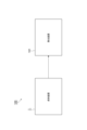
- FIG. 1 is a block diagram showing a molding system according to an embodiment of the present disclosure.
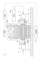
- FIG. 1 is a schematic configuration diagram showing a molding device according to an embodiment of the present disclosure.
- Fig. 2(a) is a schematic side view showing the thermal expansion unit
- Fig. 2(b) is a cross-sectional view showing the state when the nozzle seals the metal pipe material.
- FIG. 5A is a cross-sectional view taken along line Va-Va in FIG. 4
- FIG. 5B is a cross-sectional view taken along line Vb-Vb in FIG.
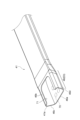
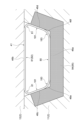
- FIG. 4 is an enlarged perspective view of a hardening adjustment portion of the molded product.
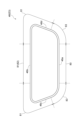
- FIG. 4 is a cross-sectional view of a hardening adjustment portion of a molded product.
- FIG. 2 is a schematic diagram for explaining a molding die.
- FIG. 13 is a cross-sectional view of a hardening adjustment portion of a molded product molded by a molding system according to
- FIG. 1 is a block diagram of a molding system 100 according to this embodiment.
- the molding system 100 is a system that molds a metal material.
- a metal pipe material is used as the metal material.
- a metal pipe is molded as the molded product.
- the forming system 100 includes a forming device 1 and a removal device 101.
- the forming device 1 is a device that performs hardening by expanding and forming a heated metal material.
- the forming device 1 forms a metal pipe by a forming method called STAF (Steel Tube Air Forming) forming.
- the removal device 101 is a device that removes unnecessary parts from the molded product molded by the molding device 1. Details of the removal device 101 will be described later.
- FIG. 2 is a schematic diagram of the molding device 1 according to this embodiment.
- the molding device 1 is a device that molds a metal pipe having a hollow shape by blow molding.
- the molding device 1 is installed on a horizontal surface.
- the molding device 1 includes a molding die 2, a drive mechanism 3, a holding unit 4, a heating unit 5, a fluid supply unit 6, a cooling unit 7, and a control unit 8.
- the metal pipe material 40 refers to a hollow article before the completion of molding in the molding device 1.
- the metal pipe material 40 is a pipe material of a steel type that can be hardened.
- the direction in which the metal pipe material 40 extends during molding may be referred to as the "longitudinal direction”
- the direction perpendicular to the longitudinal direction may be referred to as the "width direction”.
- the forming die 2 is a die for forming a metal pipe from the metal pipe material 40, and includes a lower die 11 and an upper die 12 that face each other in the vertical direction.
- the lower die 11 and the upper die 12 are made of steel blocks.
- Each of the lower die 11 and the upper die 12 has a recess for accommodating the metal pipe material 40.
- each recess forms a space of the target shape in which the metal pipe material is to be formed. Therefore, the surface of each recess becomes the forming surface of the forming die 2.
- the lower die 11 is fixed to the base 13 via a die holder or the like.
- the upper die 12 is fixed to the slide of the drive mechanism 3 via a die holder or the like.
- the drive mechanism 3 is a mechanism that moves at least one of the lower die 11 and the upper die 12. In FIG. 2, the drive mechanism 3 is configured to move only the upper die 12.
- the drive mechanism 3 includes a slide 21 that moves the upper die 12 so that the lower die 11 and the upper die 12 are aligned, a pullback cylinder 22 as an actuator that generates a force to pull the slide 21 upward, a main cylinder 23 as a drive source that pressurizes the slide 21 downward, and a drive source 24 that applies a drive force to the main cylinder 23.
- the holding unit 4 is a mechanism for holding the metal pipe material 40 disposed between the lower die 11 and the upper die 12.
- the holding unit 4 includes a lower electrode 26 and an upper electrode 27 for holding the metal pipe material 40 at one end in the longitudinal direction of the mold 2, and a lower electrode 26 and an upper electrode 27 for holding the metal pipe material 40 at the other end in the longitudinal direction of the mold 2.
- the lower electrode 26 and the upper electrode 27 on both sides in the longitudinal direction hold the metal pipe material 40 by sandwiching the end of the metal pipe material 40 from above and below.
- a groove having a shape corresponding to the outer peripheral surface of the metal pipe material 40 is formed on the upper surface of the lower electrode 26 and the lower surface of the upper electrode 27.
- the lower electrode 26 and the upper electrode 27 are provided with a driving mechanism (not shown) and can move independently in the vertical direction.
- the heating unit 5 heats the metal pipe material 40.
- the heating unit 5 is a mechanism that heats the metal pipe material 40 by passing electricity through the metal pipe material 40.
- the heating unit 5 heats the metal pipe material 40 between the lower mold 11 and the upper mold 12 while the metal pipe material 40 is separated from the lower mold 11 and the upper mold 12.
- the heating unit 5 includes a lower electrode 26 and an upper electrode 27 on both sides of the longitudinal direction as described above, and a power source 28 that passes current through these electrodes 26, 27 to the metal pipe material 40.
- the heating unit may be disposed in a process preceding the molding device 1 and may be an external heating unit.
- the fluid supply unit 6 is a mechanism for supplying high-pressure fluid into the metal pipe material 40 held between the lower die 11 and the upper die 12.
- the fluid supply unit 6 supplies high-pressure fluid to the metal pipe material 40, which has been heated by the heating unit 5 to a high temperature, to expand the metal pipe material 40.
- the fluid supply unit 6 is provided on both ends of the longitudinal direction of the mold 2.
- the fluid supply unit 6 includes a nozzle 31 that supplies fluid to the inside of the metal pipe material 40 from an opening at the end of the metal pipe material 40, a drive mechanism 32 that moves the nozzle 31 back and forth relative to the opening of the metal pipe material 40, and a supply source 33 that supplies high-pressure fluid into the metal pipe material 40 through the nozzle 31.
- the drive mechanism 32 brings the nozzle 31 into close contact with the end of the metal pipe material 40 while ensuring sealing when supplying and discharging fluid, and moves the nozzle 31 away from the end of the metal pipe material 40 at other times.
- the fluid supply unit 6 may supply a gas such as high-pressure air or an inert gas as the fluid.
- the fluid supply unit 6 may be integrated into the same device as the holding unit 4, which has a mechanism for moving the metal pipe material 40 in the vertical direction, and the heating unit 5.
- FIG. 3(a) is a schematic side view showing the thermal expansion unit 150.
- FIG. 3(b) is a cross-sectional view showing the state when the nozzle 31 seals the metal pipe material 40.
- the thermal expansion unit 150 comprises the above-mentioned lower electrode 26 and upper electrode 27, an electrode mounting unit 151 mounting the electrodes 26, 27, the above-mentioned nozzle 31 and drive mechanism 32, a lifting unit 152, and a unit base 153.
- the electrode mounting unit 151 comprises a lifting frame 154 and electrode frames 156, 157.
- the electrode frames 156, 157 function as part of the drive mechanism 60 that supports and moves the electrodes 26, 27.
- the drive mechanism 32 drives the nozzle 31, and lifts and lowers together with the electrode mounting unit 151.
- the drive mechanism 32 comprises a piston 61 that holds the nozzle 31, and a cylinder 62 that drives the piston.
- the lifting unit 152 includes a lifting frame base 64 attached to the upper surface of the unit base 153, and a lifting actuator 66 that applies lifting and lowering motion to the lifting frame 154 of the electrode mounting unit 151 by means of the lifting frame base 64.
- the lifting frame base 64 has guide parts 64a and 64b that guide the lifting and lowering motion of the lifting frame 154 relative to the unit base 153.
- the lifting unit 152 functions as part of the drive mechanism 60 of the holding part 4.
- the thermal expansion unit 150 has multiple unit bases 153 with different inclination angles of the upper surface, and by replacing these, it is possible to change and adjust the inclination angles of the lower electrode 26, upper electrode 27, nozzle 31, electrode mounting unit 151, drive mechanism 32, and lifting unit 152 all at once.
- the nozzle 31 is a cylindrical member into which the end of the metal pipe material 40 can be inserted.
- the nozzle 31 is supported by the drive mechanism 32 so that the center line of the nozzle 31 coincides with the reference line SL1.
- the inner diameter of the supply port 31a at the end of the nozzle 31 on the metal pipe material 40 side approximately coincides with the outer diameter of the metal pipe material 40 after expansion molding.
- the nozzle 31 supplies high-pressure fluid from the internal flow path 63 to the metal pipe material 40.
- An example of a high-pressure fluid is gas.
- the cooling unit 7 is a mechanism for cooling the forming die 2. By cooling the forming die 2, the cooling unit 7 can rapidly cool the expanded metal pipe material 40 when it comes into contact with the forming surface of the forming die 2.
- the cooling unit 7 includes flow paths 36 formed inside the lower die 11 and the upper die 12, and a water circulation mechanism 37 that supplies cooling water to the flow paths 36 and circulates it.
- the control unit 8 is a device that controls the entire molding device 1.
- the control unit 8 controls the drive mechanism 3, the holding unit 4, the heating unit 5, the fluid supply unit 6, and the cooling unit 7.
- the control unit 8 repeatedly performs the operation of molding the metal pipe material 40 in the molding die 2.
- control unit 8 controls the timing of conveyance from a conveying device such as a robot arm, and places the metal pipe material 40 between the lower die 11 and the upper die 12 in the open state.
- the control unit 8 may have an operator manually place the metal pipe material 40 between the lower die 11 and the upper die 12.
- the control unit 8 also controls the actuators of the holding unit 4 to support the metal pipe material 40 with the lower electrodes 26 on both sides in the longitudinal direction, and then lower the upper electrode 27 to sandwich the metal pipe material 40.
- the control unit 8 also controls the heating unit 5 to electrically heat the metal pipe material 40. As a result, an axial current flows through the metal pipe material 40, and the metal pipe material 40 itself generates heat through Joule heat due to the electrical resistance of the metal pipe material 40 itself.
- the control unit 8 controls the drive mechanism 3 to lower the upper die 12 and bring it close to the lower die 11, and closes the mold 2. Meanwhile, the control unit 8 controls the fluid supply unit 6 to seal the openings at both ends of the metal pipe material 40 with the nozzle 31 and supply fluid. As a result, the metal pipe material 40 softened by heating expands and comes into contact with the molding surface of the mold 2. The metal pipe material 40 is then molded to fit the shape of the molding surface of the mold 2. When a metal pipe with a flange is formed, a part of the metal pipe material 40 is inserted into the gap between the lower die 11 and the upper die 12, and then the mold is closed to crush the inserted part and form a flange part. When the metal pipe material 40 comes into contact with the molding surface, it is quenched by the mold 2 cooled by the cooling unit 7, and the metal pipe material 40 is quenched.
- the molded product 41 will be described with reference to Figure 4.
- the molded product 41 shown in Figure 4 is in a state after the unnecessary portion has been cut off by the removal device 101.
- the molded product 41 has a molded main body portion 45 having a pipe portion 43 and a flange portion 44, an end region 46 on one end side in the longitudinal direction, and an end region 47 on the other end side.
- the molded main body portion 45 is a portion that extends in the longitudinal direction with a generally constant cross-sectional shape.
- the pipe portion 43 is a hollow portion having a rectangular ring shape.
- the flange portion 44 is a plate-like portion that protrudes from both sides in the width direction of the pipe portion 43 by crushing a part of the metal pipe material 40.
- the end region 47 on the other end side is formed in a flat plate shape by crushing the metal pipe material 40.
- the pipe wall protrudes in an arched shape to form an air vent hole 48.
- one end region 46 has a trapezoidal cross-sectional shape.
- End region 46 has a main surface 46a corresponding to the upper side of the trapezoid, a main surface 46b corresponding to the lower side, and a pair of inclined side surfaces 46c, 46d.
- Main surface 46a is joined to another member and welded at welded portion 70.
- a notch 71 is formed in main surface 46b at a location opposite welded portion 70.
- the notch 71 is formed in a shape and range that allows a welding tool to access welded portion 70 from the main surface 46b side.
- the notch 71 is formed to extend inward in the longitudinal direction from one end 41a of molded product 41.
- the hardening mode of the molded product 41 will be described.
- the molded body portion 45 of the molded product 41 becomes the hardened portion E1, which is subjected to normal hardening.
- hardening is performed over the entire circumference in a cross-sectional view.
- each portion in the circumferential direction is hardened by hardening.
- the end region 47 on the other side becomes the non-hardened portion E2, which is not hardened.
- each portion in the circumferential direction is softened by not hardening.
- the end region 46 on one side becomes a quenching adjustment portion E3 in which the quenching mode has been adjusted.
- the quenching adjustment portion E3 a part in a cross-sectional view is quenched, and another part is not quenched.
- the main surface 46a where the welded portion 70 is formed becomes a non-quenched portion 80 that is not quenched.
- the main surface 46b and the side surfaces 46c and 46d opposite the main surface 46a become a quenched portion 81 that is quenched.
- the central region of the main surface 46b becomes a cut-out portion 82 that is removed as a notch 71.
- the corners between the main surface 46a and the side surface 46c and the corners between the main surface 46a and the side surface 46d become transition sections 83 that transition from the non-quenched portion 80 to the quenched portion 81.
- the strength of the transition section 83 is intermediate between the strength of the non-quenched portion 80 and the strength of the quenched portion 81.
- Figure 8 is a side view of the mold 2.
- the mold 2 has a quenching region 90 that forms the quenched portion E1, and a non-quenching region 91 that forms the non-quenched portion E2.
- both dies 11 and 12 are provided with a quenching mechanism 93 that only quenches the metal pipe material 40.
- the quenching mechanism 93 does not have a portion that non-quenches the corresponding portion of the metal pipe material 40.
- both dies 11 and 12 are provided with a non-quenching mechanism 94 that non-quenches the metal pipe material 40.
- the forming die 2 has a quenching mode adjustment region 92 that forms the quenching adjustment portion E3. That is, the lower die 11 (first die) and the upper die 12 (second die) have a quenching mode adjustment region 92 that adjusts the quenching mode of at least a portion of the metal pipe material 40. In this way, the quenching mode adjustment region 92 is provided at a position corresponding to the end of the metal pipe material 40 in the longitudinal direction. In the quenching mode adjustment region 92, one die 12 is provided with a quenching mechanism 93 that only quenches the metal pipe material 40, and the other die 11 is provided with a non-quenching mechanism 94 that does not quench the metal pipe material 40.
- the non-quenching mechanism 94 is constituted by a heating section 95 provided in the molds 11 and 12.
- the non-quenching mechanism 94 is constituted by a heating section 95 provided in the other mold 11.
- a medium such as steam or hot water, a heater, or electromagnetic induction may be used as the heating section 95.
- the heating section 95 heats the molding surface or the metal pipe material 40 itself, thereby preventing rapid cooling of the metal pipe material 40 during molding. As a result, quenching is not performed at the location corresponding to the non-quenching mechanism 94.
- the mechanism for constituting the non-quenching mechanism 94 is not limited to the heating section 95, and for example, a mechanism that partially prevents cooling of the cooling section 7 in the molds 11 and 12 may be provided.
- the quenching mechanism 94 is constituted by not providing a heating section 95 for the molds 11 and 12, and allowing the cooling function of the molds 11 and 12 to be exerted.
- the heating section 95 of the non-hardening mechanism 94 is provided at a position of the lower die 11 that corresponds to the non-hardening section 80 on the main surface 46a.
- the heating section 95 is not provided at positions of the die 11 that correspond to the transition section 83 and the hardening section 81.
- the heating section 95 is not provided in the upper die 12.
- the main surface 46b of the molded product 41 which is the surface facing the non-hardening portion 80 by the non-hardening mechanism 94, is removed by the removal device 101.
- the metal pipe serving as the molded product 41 has a pipe portion (molded main body portion 45 and end region 46) with a pair of main surfaces and a pair of side surfaces.
- a hardened portion 81 is provided on the upper main surface 46b
- a non-hardened portion 89 is provided on the lower main surface 46a.
- hardened portions are provided on both the upper and lower main surfaces.
- a hardened portion and a non-hardened portion are provided along the axial direction (longitudinal direction) of the metal pipe on the lower main surface of the pipe portion, and only a hardened portion is provided along the axial direction on the upper main surface of the pipe portion.
- the other end region 47 does not correspond to the pipe portion.
- a forming device 200 With reference to FIG. 8(c), a forming device 200 according to a comparative example will be described.
- the forming device 200 non-hardened regions 91 are formed at positions corresponding to both ends of the metal pipe material 40.
- a non-hardened portion 80 is formed around the entire circumference of the end region 46.
- the strength of the side surfaces 46c, 46d and main surface 46b is reduced. Therefore, deformation is concentrated in the end region 46, which causes a problem that sufficient strength of the formed product cannot be obtained.
- the mold 11 and the mold 12 have a quenching mode adjustment region 92 for adjusting the quenching mode of at least a part of the metal pipe material 40.
- one of the molds 12 is provided with a quenching mechanism 93 that only quenches the metal pipe material 40
- the other mold 11 is provided with a non-quenching mechanism 94 that does not quench the metal pipe material 40 (see (a) and (b) of FIG. 8).
- the quenching mechanism 93 can increase the strength by quenching the metal pipe material 40.
- the non-quenching mechanism 94 can form a part with a partially low strength depending on the application by not quenching the metal pipe material 40. Therefore, in the molded product 41, the strength can be reduced in parts where it is better to reduce the strength partially, such as the welded part 70, and high strength can be ensured in other parts by quenching. As a result, the strength of the molded product 41 can be improved.
- the quenching mode adjustment region 92 may be provided at a position corresponding to the end of the metal pipe material 40 in the longitudinal direction. Since the welded portion 70 and the like are likely to be formed at the end of the molded product 41, it is possible to adjust the strength at that position.
- the non-quenching mechanism 94 may be constituted by a heating section 95 provided in the other die 11. This prevents the molded product 41 from being rapidly cooled at the location of the non-quenching mechanism 94, making it possible to prevent the molded product 41 from being quenched.
- the molding system 100 includes the above-mentioned molding device 1 and a removal device 101 that removes the main surface 46b of the molded product 41 that faces the non-hardened portion 80 by the non-hardening mechanism 94. This makes it easier to insert a welding tool when forming a welded portion 70 in the non-hardened portion 80 by removing the opposing main surface 46b.
- a metal pipe has a pipe section with a pair of main surfaces and a pair of side surfaces, and one of the main surfaces of the pipe section has a hardened section and a non-hardened section along the axial direction of the metal pipe, and the other main surface of the pipe section has only hardened sections along the axial direction.
- high strength can be ensured by making parts of one main surface of the metal pipe where it is better to reduce the strength, such as welds, into non-hardened sections to reduce strength, and making the other parts into hardened sections.
- high strength can be ensured by making the other main surface out of only hardened sections. As described above, the strength of the metal pipe can be improved.
- the forming die 2 may have quenching mode adjustment regions 92 at positions corresponding to both ends of the metal pipe material.
- a non-quenching mechanism 94 may be provided in the upper die 12, and a quenching mechanism 93 may be provided in the lower die 11.
- the mold 11 and the mold 12 have a pair of opposing main surfaces 46a, 46b and a pair of side surfaces 46c, 46d in the hardening mode adjustment region 92.
- the non-hardening mechanism 94 may non-harden one of the main surfaces 46a and the pair of side surfaces 46c, 46d. In this case, the weldability between the side surfaces 46c, 46d and the mating member can be improved.
- FIG. 10 is a cross-sectional view showing a molding die 2 for molding such a molded product 41.
- the non-hardened mechanism 94 is provided not only at the location in contact with the lower main surface 46a, but also at the location in contact with the lower corners 46e and 46f and the location in contact with the side surfaces 46c and 46d.
- the shape of the molded product (mold shape in the quenching mode adjustment area 92) is not particularly limited.
- the configuration of the molding device 1 is not particularly limited, and may be modified from the structure shown in Figures 2 and 3.
- 1...molding device 40...metal pipe material (metal material), 41...molded product (metal pipe), 92...quenching mode adjustment area, 93...quenching mechanism, 94...non-quenching mechanism, 95...heating section, 100...molding system, 101...removal device.
Landscapes
- Engineering & Computer Science (AREA)
- Mechanical Engineering (AREA)
- Heat Treatment Of Articles (AREA)
- Physics & Mathematics (AREA)
- Fluid Mechanics (AREA)
Priority Applications (3)
| Application Number | Priority Date | Filing Date | Title |
|---|---|---|---|
| CN202480044356.7A CN121464006A (zh) | 2023-07-26 | 2024-06-07 | 成型装置、成型系统及金属管 |
| JP2025535616A JPWO2025022840A1 (https=) | 2023-07-26 | 2024-06-07 | |
| KR1020257038710A KR20260048184A (ko) | 2023-07-26 | 2024-06-07 | 성형장치, 성형시스템, 및 금속파이프 |
Applications Claiming Priority (2)
| Application Number | Priority Date | Filing Date | Title |
|---|---|---|---|
| JP2023121418 | 2023-07-26 | ||
| JP2023-121418 | 2023-07-26 |
Publications (1)
| Publication Number | Publication Date |
|---|---|
| WO2025022840A1 true WO2025022840A1 (ja) | 2025-01-30 |
Family
ID=94374720
Family Applications (1)
| Application Number | Title | Priority Date | Filing Date |
|---|---|---|---|
| PCT/JP2024/020915 Pending WO2025022840A1 (ja) | 2023-07-26 | 2024-06-07 | 成形装置、成形システム、及び金属パイプ |
Country Status (4)
| Country | Link |
|---|---|
| JP (1) | JPWO2025022840A1 (https=) |
| KR (1) | KR20260048184A (https=) |
| CN (1) | CN121464006A (https=) |
| WO (1) | WO2025022840A1 (https=) |
Citations (7)
| Publication number | Priority date | Publication date | Assignee | Title |
|---|---|---|---|---|
| JP2005161366A (ja) * | 2003-12-03 | 2005-06-23 | Nippon Steel Corp | 鋼板のプレス成形方法及び装置 |
| WO2008123506A1 (ja) * | 2007-04-04 | 2008-10-16 | Sumitomo Metal Industries, Ltd. | 自動車車体用強度部材、フロントサイドメンバー及び自動車車体の側部構造 |
| JP2008542031A (ja) * | 2005-05-30 | 2008-11-27 | ティッセンクルップ スチール アクチェンゲゼルシャフト | 種々の材料特性を有する隣接部分を含む金属コンポーネントを製造する方法 |
| JP2011000617A (ja) * | 2009-06-19 | 2011-01-06 | Nippon Steel Corp | 金属管の熱間プレス成形装置およびその方法 |
| JP2011523375A (ja) * | 2008-07-25 | 2011-08-11 | ヒュンダイ スチール カンパニー | プレス硬化用金型の冷却装置 |
| JP2013188793A (ja) | 2012-03-15 | 2013-09-26 | Kyoho Mach Works Ltd | 熱間プレス装置及び熱間プレス方法 |
| JP2016528043A (ja) * | 2013-07-05 | 2016-09-15 | オートテック エンジニアリング エー.アイ.イー. | 変形配向の制御された金属部品 |
-
2024
- 2024-06-07 WO PCT/JP2024/020915 patent/WO2025022840A1/ja active Pending
- 2024-06-07 CN CN202480044356.7A patent/CN121464006A/zh active Pending
- 2024-06-07 JP JP2025535616A patent/JPWO2025022840A1/ja active Pending
- 2024-06-07 KR KR1020257038710A patent/KR20260048184A/ko active Pending
Patent Citations (7)
| Publication number | Priority date | Publication date | Assignee | Title |
|---|---|---|---|---|
| JP2005161366A (ja) * | 2003-12-03 | 2005-06-23 | Nippon Steel Corp | 鋼板のプレス成形方法及び装置 |
| JP2008542031A (ja) * | 2005-05-30 | 2008-11-27 | ティッセンクルップ スチール アクチェンゲゼルシャフト | 種々の材料特性を有する隣接部分を含む金属コンポーネントを製造する方法 |
| WO2008123506A1 (ja) * | 2007-04-04 | 2008-10-16 | Sumitomo Metal Industries, Ltd. | 自動車車体用強度部材、フロントサイドメンバー及び自動車車体の側部構造 |
| JP2011523375A (ja) * | 2008-07-25 | 2011-08-11 | ヒュンダイ スチール カンパニー | プレス硬化用金型の冷却装置 |
| JP2011000617A (ja) * | 2009-06-19 | 2011-01-06 | Nippon Steel Corp | 金属管の熱間プレス成形装置およびその方法 |
| JP2013188793A (ja) | 2012-03-15 | 2013-09-26 | Kyoho Mach Works Ltd | 熱間プレス装置及び熱間プレス方法 |
| JP2016528043A (ja) * | 2013-07-05 | 2016-09-15 | オートテック エンジニアリング エー.アイ.イー. | 変形配向の制御された金属部品 |
Also Published As
| Publication number | Publication date |
|---|---|
| KR20260048184A (ko) | 2026-04-09 |
| JPWO2025022840A1 (https=) | 2025-01-30 |
| CN121464006A (zh) | 2026-02-03 |
Similar Documents
| Publication | Publication Date | Title |
|---|---|---|
| JPH1179765A (ja) | ガラス容器の製造方法および製造装置 | |
| JP7668802B2 (ja) | 成形装置 | |
| WO2025022840A1 (ja) | 成形装置、成形システム、及び金属パイプ | |
| US20240253103A1 (en) | Forming device and forming method | |
| US20240149323A1 (en) | Molding device | |
| US12358037B2 (en) | Forming device and forming method | |
| WO2023157698A1 (ja) | 成形装置 | |
| WO2022050074A1 (ja) | 成形型 | |
| WO2023038083A1 (ja) | 成形装置 | |
| US20260084200A1 (en) | Forming device | |
| WO2024089990A1 (ja) | 成形装置 | |
| CA3162758C (en) | Forming device and forming method | |
| JP2024064701A (ja) | 成形装置、及び金属部材 | |
| WO2024089989A1 (ja) | 成形装置、及び金属部材 | |
| JP2021053688A (ja) | 成形装置及びブロー成形用の金属パイプ材料 | |
| JP7640522B2 (ja) | 成形システム、及び成形方法 | |
| US20260091424A1 (en) | Forming system | |
| WO2022186055A1 (ja) | 成形システム |
Legal Events
| Date | Code | Title | Description |
|---|---|---|---|
| 121 | Ep: the epo has been informed by wipo that ep was designated in this application |
Ref document number: 24845222 Country of ref document: EP Kind code of ref document: A1 |
|
| ENP | Entry into the national phase |
Ref document number: 2025535616 Country of ref document: JP Kind code of ref document: A |
|
| WWE | Wipo information: entry into national phase |
Ref document number: 2025535616 Country of ref document: JP |
|
| WWE | Wipo information: entry into national phase |
Ref document number: 2024845222 Country of ref document: EP |
|
| NENP | Non-entry into the national phase |
Ref country code: DE |