WO2025022622A1 - 射出成形機 - Google Patents
射出成形機 Download PDFInfo
- Publication number
- WO2025022622A1 WO2025022622A1 PCT/JP2023/027432 JP2023027432W WO2025022622A1 WO 2025022622 A1 WO2025022622 A1 WO 2025022622A1 JP 2023027432 W JP2023027432 W JP 2023027432W WO 2025022622 A1 WO2025022622 A1 WO 2025022622A1
- Authority
- WO
- WIPO (PCT)
- Prior art keywords
- pair
- guide members
- linear guide
- injection molding
- molding machine
- Prior art date
- Legal status (The legal status is an assumption and is not a legal conclusion. Google has not performed a legal analysis and makes no representation as to the accuracy of the status listed.)
- Pending
Links
Images



Classifications
-
- B—PERFORMING OPERATIONS; TRANSPORTING
- B22—CASTING; POWDER METALLURGY
- B22D—CASTING OF METALS; CASTING OF OTHER SUBSTANCES BY THE SAME PROCESSES OR DEVICES
- B22D17/00—Pressure die casting or injection die casting, i.e. casting in which the metal is forced into a mould under high pressure
- B22D17/20—Accessories: Details
-
- B—PERFORMING OPERATIONS; TRANSPORTING
- B29—WORKING OF PLASTICS; WORKING OF SUBSTANCES IN A PLASTIC STATE IN GENERAL
- B29C—SHAPING OR JOINING OF PLASTICS; SHAPING OF MATERIAL IN A PLASTIC STATE, NOT OTHERWISE PROVIDED FOR; AFTER-TREATMENT OF THE SHAPED PRODUCTS, e.g. REPAIRING
- B29C45/00—Injection moulding, i.e. forcing the required volume of moulding material through a nozzle into a closed mould; Apparatus therefor
- B29C45/17—Component parts, details or accessories; Auxiliary operations
-
- B—PERFORMING OPERATIONS; TRANSPORTING
- B29—WORKING OF PLASTICS; WORKING OF SUBSTANCES IN A PLASTIC STATE IN GENERAL
- B29C—SHAPING OR JOINING OF PLASTICS; SHAPING OF MATERIAL IN A PLASTIC STATE, NOT OTHERWISE PROVIDED FOR; AFTER-TREATMENT OF THE SHAPED PRODUCTS, e.g. REPAIRING
- B29C45/00—Injection moulding, i.e. forcing the required volume of moulding material through a nozzle into a closed mould; Apparatus therefor
- B29C45/17—Component parts, details or accessories; Auxiliary operations
- B29C45/20—Injection nozzles
-
- B—PERFORMING OPERATIONS; TRANSPORTING
- B29—WORKING OF PLASTICS; WORKING OF SUBSTANCES IN A PLASTIC STATE IN GENERAL
- B29C—SHAPING OR JOINING OF PLASTICS; SHAPING OF MATERIAL IN A PLASTIC STATE, NOT OTHERWISE PROVIDED FOR; AFTER-TREATMENT OF THE SHAPED PRODUCTS, e.g. REPAIRING
- B29C45/00—Injection moulding, i.e. forcing the required volume of moulding material through a nozzle into a closed mould; Apparatus therefor
- B29C45/17—Component parts, details or accessories; Auxiliary operations
- B29C45/84—Safety devices
Definitions
- This disclosure relates to an injection molding machine.
- JP 2019-025701 A discloses an injection molding machine in which a fixed platen and a nozzle touch mechanism are connected by a connecting member having an arm extending upward from a support base supported by the machine base.
- the present disclosure relates to an injection molding machine comprising an injection machine that injects molding material, a fixed platen to which mold pieces are fixed, and a structure disposed between the injection machine and the fixed platen, and further comprising a first linear motion mechanism including a first support member that supports the injection machine and a pair of first linear motion guide members that guide the first support member in a direction along the injection direction of the injection machine, and a second linear motion mechanism including a second support member that supports the structure and one or a pair of second linear motion guide members that guide the second support member in a direction along the injection direction, and when there is one second linear motion guide member, at least a portion of the second linear motion guide member is , when viewed from above, it is disposed between a pair of the first linear guide members, and when the second linear guide members are a pair, at least a portion of the pair of second linear guide members is disposed between the pair of first linear guide members in a plan view, or at least a portion of the pair of first linear guide members is disposed between the pair of second
- FIG. 1 is a side view showing the configuration of an injection molding machine.
- FIG. 2 is a side view showing a portion of the injection molding machine in an injection state.
- FIG. 3 is a perspective view showing a part of the injection molding machine in a nozzle touch state.
- FIG. 4 is a diagram showing the relationship between the connecting member and the injection machine.
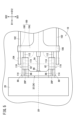
- FIG. 5 is a top view showing a portion of the injection molding machine.
- FIG. 6 is a side view showing the configuration of an injection molding machine according to the first modified example.
- An object of the present disclosure is to provide an injection molding machine that can bring the fixed platen and the injection machine into good contact with each other.
- Fig. 1 is a side view showing the configuration of an injection molding machine 1
- Fig. 2 is a side view showing a part of the injection molding machine 1 in an injection state.
- a front-rear direction D1 corresponds to the height direction of the injection molding machine 1.
- the left-right direction D3 corresponds to the width direction of the injection molding machine 1.
- one side of the front-rear direction D1 is the front direction D11, and the other side of the front-rear direction D1 is the rear direction D12.
- One side of the up-down direction D2 is the upward direction D21, and the other side of the up-down direction D2 is the downward direction D22.
- One side of the left-right direction D3 is the left direction D31 (see FIG. 3), and the other side of the left-right direction D3 is the right direction D32 (see FIG. 3).
- the downward direction D22 is the direction in which gravity acts, but is not limited to this.
- the injection molding machine 1 comprises a machine base 10, a clamping unit 12, and an injection unit 14.
- the machine base 10 is a stand for mounting the clamping unit 12 and the injection unit 14.
- the machine base 10 has a first machine base part 10A on which the clamping unit 12 is mounted, and a second machine base part 10B on which the injection unit 14 is mounted.
- the first machine base part 10A and the second machine base part 10B may be separably connected. In this case, for example, during maintenance, the connected first machine base part 10A and second machine base part 10B can be separated. Therefore, in such an injection molding machine 1, the user can easily access the clamping unit 12 or the injection unit 14, making maintenance easy.
- the top surface 10F1 of the first machine base 10A is lower than the top surface 10F2 of the second machine base 10B.
- the height reference in this embodiment is the bottom end surface 10F3 of the machine base 10.
- the bottom end surface 10F3 of the machine base 10 abuts against a foundation surface such as the ground.
- the mold clamping unit 12 has a fixed platen 20, a rear platen 22, a movable platen 24, a mold 26, a number of tie bars 28, and a platen drive mechanism 29.
- the fixed platen 20 and the rear platen 22 are installed at a distance from each other on the upper surface 10F1 of the first machine base 10A.
- the fixed platen 20 has a nozzle insertion hole 20H formed therein.
- the movable platen 24 is disposed between the fixed platen 20 and the rear platen 22.
- the mold 26 is composed of a first mold piece 26A and a second mold piece 26B.
- the first mold piece 26A is attached to the end face of the fixed platen 20 in the forward direction D11.
- the second mold piece 26B is attached to the end face of the movable platen 24 in the rearward direction D12.
- Each of the tie bars 28 is a rod-shaped member. One end of the tie bars 28 is fixed to the fixed platen 20. The other end of the tie bars 28 is fixed to the rear platen 22. The tie bars 28 pass through the movable platen 24. The movable platen 24 is movable along the tie bars 28.
- the platen drive mechanism 29 is a mechanism that moves the movable platen 24.
- the platen drive mechanism 29 closes the mold 26 by moving the movable platen 24 in the rear direction D12.
- the platen drive mechanism 29 opens the mold 26 by moving the movable platen 24 in the forward direction D11.
- the mold 26 is closed, the first mold piece 26A is in contact with the second mold piece 26B.
- the mold 26 is open, the first mold piece 26A is not in contact with the second mold piece 26B.
- the injection unit 14 has an injection machine 30 and a structure 32.
- the structure 32 is located between the fixed platen 20 and the injection machine 30.
- the structure 32 is a connecting member 34 that connects the fixed platen 20 and the injection machine 30.
- the structure 32 may also be provided in the mold clamping unit 12.
- the injector 30 is a device that injects molding material.
- the injector 30 has an injector body 42, a cylinder section 44, a nozzle 46, and a nozzle touch mechanism 48.
- the injector body 42 is slidable in the forward direction D11 or the backward direction D12 relative to the machine base 10.
- the cylinder section 44 is fixed to the injector body 42 and extends from the injector body 42 in the forward direction D11.
- the nozzle 46 extends from the tip of the cylinder section 44 in the forward direction D11.
- the nozzle touch mechanism 48 is a mechanism that moves the injection machine 30 in the forward direction D11 or the backward direction D12.
- the nozzle touch mechanism 48 has a motor 52, a ball screw shaft 54, and a ball screw nut 56.
- the motor 52 is a motor for moving the injection machine 30 in the forward direction D11 or the backward direction D12.
- the ball screw shaft 54 extends along the forward/backward direction D1.
- the end of the ball screw shaft 54 in the backward direction D12 is connected to the rotor shaft of the motor 52 via a coupling 58.
- the end of the ball screw shaft 54 in the forward direction D11 is connected to the connecting member 34.
- the ball screw nut 56 is screwed onto the ball screw shaft 54, and is connected via a spring 60 to the base 104 to which the injection machine main body 42 is fixed.
- the spring 60 does not have to be provided. In this case, the ball screw nut 56 is connected to the base 104 without the spring 60.
- the ball screw shaft 54 connected to the rotor shaft of the motor 52 rotates, and the ball screw nut 56 screwed onto the ball screw shaft 54 moves in the forward direction D11.
- the nozzle 46 of the injector 30 is inserted into the nozzle insertion hole 20H of the fixed platen 20, resulting in a nozzle touch state (see FIG. 2).
- the nozzle touch state is a state in which the nozzle 46 abuts against the nozzle abutment portion (spool) of the first mold piece 26A. In this nozzle touch state, the mold 26 is clamped.
- the nozzle touch mechanism 48 moves the injector 30 in the forward direction D11 relative to the machine base 10 so that the nozzle 46 comes into contact with the first mold half 26A (see FIG. 2). That is, even after the nozzle 46 comes into contact with the first mold half 26A, the nozzle touch mechanism 48 continues to drive the motor 52 in the second rotation direction to move the ball screw nut 56 in the forward direction D11. This compresses the spring 60, and the nozzle touch state is maintained by the compression reaction force.
- the nozzle touch state is maintained by continuing to drive the motor 52 in the second rotation direction.
- the nozzle touch state can be maintained even if the motor 52 is stopped with the spring 60 in a compressed state.
- the injector 30 injects the molding material into the mold 26 in the nozzle touch state.
- Figure 3 is a perspective view showing a part of the injection molding machine 1 in the nozzle touch state.
- the connecting member 34 has a support base portion 62 and a pair of arms 64.
- the connecting member 34 is formed in a roughly L-shape when viewed from the side.
- the support base 62 can slide in the forward direction D11 or the backward direction D12 relative to the machine base 10.
- a bearing portion 66 is provided on the end face of the support base 62 in the backward direction D12.
- One end of the ball screw shaft 54 of the nozzle touch mechanism 48 is attached to the bearing portion 66.
- the bearing portion 66 is a part that is connected to the injection machine 30.
- the pair of arms 64 are arranged at a distance from each other in the left-right direction D3.
- the pair of arms 64 rise up in the upward direction D21 from the end of the support base 62 in the forward direction D11.
- Each of the pair of arms 64 has a platen connecting portion 80.
- Each platen connecting portion 80 is a portion that is connected to the fixed platen 20, and is located at the upper portion of the arm 64.
- Each platen connection part 80 is provided symmetrically on either side of the nozzle 46. Since each platen connection part 80 has the same configuration, the configuration of one platen connection part 80 will be described below.
- the platen connecting portion 80 is fixed to a base portion 20P that protrudes from the end face of the fixed platen 20 in the rear direction D12 in a state in which it can rotate with respect to the fixed platen 20.
- the platen connecting portion 80 has a notch portion 82, a connecting pin 84, and a rotating member 86. Note that the base portion 20P does not have to be provided. In this case, the platen connecting portion 80 is fixed to the end face of the fixed platen 20 in the rear direction D12.
- the cutout portion 82 is formed in the upper portion of the arm portion 64.
- the cutout portion 82 extends in the front-rear direction D1 from the end face of the arm portion 64 in the forward direction D11 to the end face of the arm portion 64 in the rearward direction D12.
- the connecting pin 84 is disposed in the cutout 82.
- the connecting pin 84 extends in the left-right direction D3 and is fixed to the arm 64. In other words, the connecting pin 84 cannot rotate relative to the arm 64, and cannot slide relative to the arm 64 in any of the forward-backward direction D1, the up-down direction D2, and the left-right direction D3.
- a connecting pin 84 that is disposed in the cutout portion 82 passes through the rotating member 86.
- the rotating member 86 is fixed to the fixed platen 20 in a state in which it can rotate around the connecting pin 84.
- FIG. 4 is a diagram showing the relationship between the connecting member 34 and the injection machine 30.
- the connecting pin 84 of the connecting member 34 is located at approximately the same height as the nozzle 46 of the injection machine 30. In other words, the connecting pin 84 passes through the nozzle center line LN.
- the nozzle center line LN is an imaginary line that extends the axis of the nozzle 46, and is included in a plane parallel to the upper surface 10F2 of the second machine base 10B.
- a nozzle touch force P2 is generated in the connecting member 34 as a reaction force to the pressing force P1.
- the support base portion 62 can slide in the forward direction D11 or the backward direction D12 relative to the machine base 10, so the nozzle touch force P2 is generated mainly in the connecting pin 84 of the connecting member 34. Since the connecting pin 84 passes through the nozzle center line LN, the line of action of the pressing force P1 and its reaction force, the nozzle touch force P2, is collinear with the nozzle center line LN. Therefore, the moment MF is not generated in the direction in which the fixed platen 20 falls, and the effect of the connecting member 34 in preventing the fixed platen 20 from falling can be improved.
- the connecting pin 84 does not have to pass through the nozzle center line LN. In this case, even if the connecting member 34 tilts toward the fixed platen 20, the moment MF generated by the tilt can be converted into rotation of the platen connecting portion 80. As a result, the connecting member 34 can be effective in preventing the fixed platen 20 from falling over.
- the injection molding machine 1 of this embodiment has a first linear motion mechanism 90 and a second linear motion mechanism 92.
- the first linear motion mechanism 90 and the second linear motion mechanism 92 are configured so that the fixed platen 20 and the injection machine 30 can be brought close to each other.
- the first linear motion mechanism 90 is provided on the second machine base 10B.
- the first linear motion mechanism 90 includes a first support member 100 and a pair of first linear motion guide members 102.
- the second linear motion mechanism 92 is provided on the first machine base 10A.
- the second linear motion mechanism 92 includes a second support member 110 and a pair of second linear motion guide members 112.
- the first support member 100 is a member that supports the injection machine 30.
- the first support member 100 has a base portion 104 and a plurality of guide blocks 106.
- the base portion 104 is a member to which the injection machine main body 42 is fixed.
- the plurality of guide blocks 106 are members that are provided slidably with respect to the pair of first linear guide members 102.
- the plurality of guide blocks 106 support the base portion 104.
- the number of guide blocks 106 provided on one first linear guide member 102 is one or more. In this embodiment, two guide blocks 106 are provided on one first linear guide member 102 (see FIG. 1 or FIG. 2), but this is not limited to this.
- the base portion 104 and the multiple guide blocks 106 may be formed integrally or separately. When the base portion 104 and the multiple guide blocks 106 are formed separately, the base portion 104 may be part of the injection machine 30.
- the pair of first linear guide members 102 are members that guide the first support member 100 in a direction along the injection direction of the injector 30 (front-rear direction D1).
- the pair of first linear guide members 102 are installed on the upper surface 10F2 of the second machine base 10B.
- the pair of first linear guide members 102 are installed with a gap in the left-right direction D3 and extend parallel to each other along the front-rear direction D1.
- the pair of first linear guide members 102 are symmetrical with respect to the nozzle center line LN. In other words, the pair of first linear guide members 102 are arranged symmetrically with respect to the axis of the nozzle 46.
- the second support member 110 is a member that supports the structure 32.
- the second support member 110 supports the connecting member 34.
- the second support member 110 has a plurality of guide blocks 114.
- the support base portion 62 of the connecting member 34 is fixed to the plurality of guide blocks 114.
- the support base portion 62 and the plurality of guide blocks 114 may be formed integrally.
- the support base portion 62 is a part of the second support member 110, and the pair of arms 64 of the connecting member 34 rise from the second support member 110 in the upward direction D21.
- the multiple guide blocks 114 are provided slidably on the pair of second linear guide members 112.
- the number of guide blocks 114 provided on one second linear guide member 112 is one or more. In this embodiment, two guide blocks 114 are provided on one second linear guide member 112, but this is not limited to this.
- the pair of second linear guide members 112 are members that guide the second support member 110 in a direction along the injection direction of the injection machine 30 (front-rear direction D1).
- the amount of movement of the second support member 110 is smaller than the amount of movement of the first support member 100.
- the amount of movement of the second support member 110 is the amount by which the second support member 110 can move in the front-rear direction D1 along the pair of second linear guide members 112.
- the amount of movement of the first support member 100 is the amount by which the first support member 100 can move in the front-rear direction D1 along the pair of first linear guide members 102.
- the pair of second linear guide members 112 are installed on the upper surface 10F2 of the second machine base 10B.
- the pair of second linear guide members 112 are installed with a gap in the left-right direction D3 and extend parallel to each other along the front-rear direction D1.
- the pair of second linear guide members 112 are symmetrical with respect to the nozzle center line LN. In other words, the pair of second linear guide members 112 are arranged symmetrically with respect to the axis of the nozzle 46.
- FIG. 5 is a top view showing a portion of the injection molding machine 1. At least a portion of the pair of second linear guide members 112 is located between the pair of first linear guide members 102 in a plan view.
- the height of the position where the pair of first linear guide members 102 is provided and the height of the position where the pair of second linear guide members 112 is provided are different from each other.
- the position where the pair of second linear guide members 112 is provided is lower than the position where the pair of first linear guide members 102 are provided.
- the position where the pair of second linear guide members 112 is provided is the upper surface 10F1 of the first machine base 10A.
- the position where the pair of first linear guide members 102 is provided is the upper surface 10F2 of the second machine base 10B.
- the upper surface 10F1 of the first machine base 10A is lower than the upper surface 10F2 of the second machine base 10B.
- the pair of second linear guide members 112 and the pair of first linear guide members 102 have overlapping portions.
- the rear ends of the pair of second linear guide members 112 and the front ends of the pair of first linear guide members 102 overlap in the left-right direction D3.
- the rear ends of the pair of second linear guide members 112 and the front ends of the pair of first linear guide members 102 overlap in the up-down direction D2.
- a part of the first support member 100 and a part of the second support member 110 overlap in a plan view.
- a part of the connecting member 34 is located between a part of the first support member 100 and a part of the second support member 110. In this state, the connecting member 34 is not in contact with either the first support member 100 or the second support member 110.
- the second linear motion mechanism 92 may be provided on the second machine base 10B.
- a surface 10F4 lower than the installation surface of the first linear motion guide member 102 is provided on the second machine base 10B, and a pair of second linear motion guide members 112 are installed on the surface 10F4.
- the first linear motion mechanism 90 may include one or more first auxiliary guide members (not shown) in addition to the pair of first linear motion guide members 102.
- the first auxiliary guide members extend parallel to the pair of first linear motion guide members 102 along the front-rear direction D1.
- the first auxiliary guide members may be disposed between the pair of first linear motion guide members 102.
- the first auxiliary guide members may be disposed outward from the pair of first linear motion guide members 102 in the left direction D31 or the right direction D32.
- the second linear motion mechanism 92 may include one or more second auxiliary guide members (not shown) in addition to the pair of second linear motion guide members 112.
- the second auxiliary guide members extend parallel to the pair of second linear motion guide members 112 along the front-rear direction D1.
- the second auxiliary guide members may be disposed between the pair of second linear motion guide members 112.
- the second auxiliary guide members may be disposed outward from the pair of second linear motion guide members 112 in the left direction D31 or the right direction D32.
- the second linear motion mechanism 92 may include one second linear motion guide member 112 instead of the pair of second linear motion guide members 112. In this case, at least a portion of the one second linear motion guide member 112 is disposed between the pair of first linear motion guide members 102 in a plan view.
- first linear motion mechanism 90 and the second linear motion mechanism 92 may be provided in a reversed relationship to that of the above embodiment. That is, at least a part of the pair of first linear motion guide members 102 may be disposed between the pair of second linear motion guide members 112 in a plan view. Alternatively, the position where the pair of second linear motion guide members 112 are provided may be higher than the position where the pair of first linear motion guide members 102 are provided.
- the upper surface 10F1 of the first machine stand 10A and the upper surface 10F2 of the second machine stand 10B may be at the same height.
- at least one of the upper surface 10F1 of the first machine stand 10A and the upper surface 10F2 of the second machine stand 10B is provided with a height adjustment member (not shown).
- at least one of the first installation surface on which the first linear guide member 102 is installed and the second installation surface on which the second linear guide member 112 is installed becomes the upper surface of the height adjustment member.
- a groove may be provided on at least one of the upper surface 10F1 of the first machine stand 10A and the upper surface 10F2 of the second machine stand 10B. In this case, at least one of the first installation surface and the second installation surface becomes the bottom surface of the groove.
- the height of the first installation surface and the height of the second installation surface are different.
- the structure 32 is not limited to the connecting member 34.
- a support member that supports the cylinder portion 44 may be used.
- a resin scattering prevention cover that is slidable in the injection direction of the molding material may be used.
- the pair of second linear guide members 112 is disposed between the pair of first linear guide members 102 in a plan view.
- at least a part of the pair of second linear guide members 112 is disposed between the pair of first linear guide members 102 in a plan view.
- the height of the position where the pair of first linear guide members 102 are provided is different from the height of the position where the pair of second linear guide members 112 are provided.
- the movable amount of the second support member 110 is smaller than the movable amount of the first support member 100.
- the injection molding machine 1 of the above embodiment when the injection machine 30 is brought closer to the fixed platen 20, interference between the first support member 100 and the second support member 110 can be avoided. As a result, the fixed platen 20 and the injection machine 30 can be brought closer to each other in a good manner.
- An injection molding machine (1) comprising an injector (30) for injecting a molding material, a stationary platen (20) to which a mold piece (26A) is fixed, and a structure (32) disposed between the injector and the stationary platen, the injection molding machine (1) further comprising a first support member (100) for supporting the injector, a first linear motion mechanism (90) including a pair of first linear motion guide members (102) for guiding the first support member in a direction (D1) along the injection direction of the injector, a second support member (110) for supporting the structure, and a second linear motion mechanism (92) including one or a pair of second linear motion guide members (112) for guiding the second support member in a direction along the injection direction,
- at least a portion of the second linear guide member is arranged between the pair of first linear guide members in a plan view, and when the second linear guide members are a pair, at least a portion of the pair of second linear guide members is arranged between the pair of first linear guide members in a plan view,
- a position at which one or a pair of the second linear guide members are provided may be lower than a position at which a pair of the first linear guide members are provided.
- Appendix 3 In the injection molding machine described in Appendix 1 or 2, when a nozzle (46) of the injection machine is in contact with the mold pieces, a portion of the first support member and a portion of the second support member may overlap in a plan view.
- a portion of the structure may be positioned between a portion of the first support member and a portion of the second support member when a nozzle of the injection machine is in contact with the mold pieces.
- the pair of first linear guide members may be arranged symmetrically with respect to an axis of a nozzle of the injector, and the pair of second linear guide members may be arranged symmetrically with respect to an axis of the nozzle of the injector.
- the second support member may have a plurality of guide blocks (114) each moving on the second linear guide member, and the structure may be supported by the plurality of guide blocks.
- Appendix 8 An injection molding machine according to any one of Appendices 1 to 7, comprising a machine base (10) having a first mounting surface (10F2) on which the first linear guide member is mounted and a second mounting surface (10F1) on which the second linear guide member is mounted, and the second mounting surface may be lower than the first mounting surface.
- the structure may be a connecting member (34) that connects the fixed platen and the injection machine.
Landscapes
- Engineering & Computer Science (AREA)
- Mechanical Engineering (AREA)
- Manufacturing & Machinery (AREA)
- Injection Moulding Of Plastics Or The Like (AREA)
Priority Applications (4)
| Application Number | Priority Date | Filing Date | Title |
|---|---|---|---|
| PCT/JP2023/027432 WO2025022622A1 (ja) | 2023-07-26 | 2023-07-26 | 射出成形機 |
| DE112023006381.8T DE112023006381T5 (de) | 2023-07-26 | 2023-07-26 | Spritzgießmaschine |
| JP2025535508A JPWO2025022622A1 (https=) | 2023-07-26 | 2023-07-26 | |
| CN202380100557.XA CN121548491A (zh) | 2023-07-26 | 2023-07-26 | 注射成形机 |
Applications Claiming Priority (1)
| Application Number | Priority Date | Filing Date | Title |
|---|---|---|---|
| PCT/JP2023/027432 WO2025022622A1 (ja) | 2023-07-26 | 2023-07-26 | 射出成形機 |
Publications (1)
| Publication Number | Publication Date |
|---|---|
| WO2025022622A1 true WO2025022622A1 (ja) | 2025-01-30 |
Family
ID=94374550
Family Applications (1)
| Application Number | Title | Priority Date | Filing Date |
|---|---|---|---|
| PCT/JP2023/027432 Pending WO2025022622A1 (ja) | 2023-07-26 | 2023-07-26 | 射出成形機 |
Country Status (4)
| Country | Link |
|---|---|
| JP (1) | JPWO2025022622A1 (https=) |
| CN (1) | CN121548491A (https=) |
| DE (1) | DE112023006381T5 (https=) |
| WO (1) | WO2025022622A1 (https=) |
Citations (7)
| Publication number | Priority date | Publication date | Assignee | Title |
|---|---|---|---|---|
| JPH08118403A (ja) * | 1994-10-24 | 1996-05-14 | Sumitomo Heavy Ind Ltd | スタック金型用射出成形機 |
| JP2012011767A (ja) * | 2009-12-17 | 2012-01-19 | Toshiba Mach Co Ltd | 射出成形機 |
| JP2017222031A (ja) * | 2016-06-13 | 2017-12-21 | ファナック株式会社 | 射出成形機 |
| JP6557296B2 (ja) * | 2017-07-27 | 2019-08-07 | ファナック株式会社 | 射出成形機 |
| JP2020104500A (ja) * | 2018-12-28 | 2020-07-09 | 住友重機械工業株式会社 | 射出成形機、および射出成形機用の接触防止カバー |
| US11141895B2 (en) * | 2018-03-07 | 2021-10-12 | Engel Austria Gmbh | Shaping machine and method of operating a shaping machine |
| JP6947957B1 (ja) * | 2020-05-28 | 2021-10-13 | ファナック株式会社 | 射出成形機 |
-
2023
- 2023-07-26 CN CN202380100557.XA patent/CN121548491A/zh active Pending
- 2023-07-26 JP JP2025535508A patent/JPWO2025022622A1/ja active Pending
- 2023-07-26 DE DE112023006381.8T patent/DE112023006381T5/de active Pending
- 2023-07-26 WO PCT/JP2023/027432 patent/WO2025022622A1/ja active Pending
Patent Citations (7)
| Publication number | Priority date | Publication date | Assignee | Title |
|---|---|---|---|---|
| JPH08118403A (ja) * | 1994-10-24 | 1996-05-14 | Sumitomo Heavy Ind Ltd | スタック金型用射出成形機 |
| JP2012011767A (ja) * | 2009-12-17 | 2012-01-19 | Toshiba Mach Co Ltd | 射出成形機 |
| JP2017222031A (ja) * | 2016-06-13 | 2017-12-21 | ファナック株式会社 | 射出成形機 |
| JP6557296B2 (ja) * | 2017-07-27 | 2019-08-07 | ファナック株式会社 | 射出成形機 |
| US11141895B2 (en) * | 2018-03-07 | 2021-10-12 | Engel Austria Gmbh | Shaping machine and method of operating a shaping machine |
| JP2020104500A (ja) * | 2018-12-28 | 2020-07-09 | 住友重機械工業株式会社 | 射出成形機、および射出成形機用の接触防止カバー |
| JP6947957B1 (ja) * | 2020-05-28 | 2021-10-13 | ファナック株式会社 | 射出成形機 |
Also Published As
| Publication number | Publication date |
|---|---|
| DE112023006381T5 (de) | 2026-03-05 |
| JPWO2025022622A1 (https=) | 2025-01-30 |
| CN121548491A (zh) | 2026-02-17 |
Similar Documents
| Publication | Publication Date | Title |
|---|---|---|
| JP6557296B2 (ja) | 射出成形機 | |
| US7168946B2 (en) | Movable-die support device and die clamping unit | |
| JP4827880B2 (ja) | プラテン支持装置及び型締装置 | |
| US7455511B2 (en) | Mold clamping mechanism for injection molding machine | |
| JPH07119039B2 (ja) | 射出成形機 | |
| CN100496934C (zh) | 用于活动部分的支承装置和模具夹紧单元 | |
| WO2025022622A1 (ja) | 射出成形機 | |
| US7351055B2 (en) | Injection molding machine | |
| JP3648178B2 (ja) | 射出成形機の固定金型支持装置 | |
| KR101901282B1 (ko) | 타이바레스 사출성형기 | |
| JP6947957B1 (ja) | 射出成形機 | |
| WO2021241464A1 (ja) | 射出成形機 | |
| US12128597B2 (en) | Barrel support apparatus and injection apparatus | |
| JP3635220B2 (ja) | 射出成形機 | |
| CN100368178C (zh) | 注射成型机 | |
| WO2024161475A1 (ja) | 射出成形機 | |
| US20140234472A1 (en) | Closing unit of an injection molding machine | |
| JP3183999B2 (ja) | 射出成形機 | |
| JPWO2025022622A5 (https=) | ||
| JP2009154475A (ja) | 型締め装置および射出成形機 | |
| JP2005319664A (ja) | 型締め装置 | |
| JP4270327B1 (ja) | 射出成形機の型締装置 | |
| JP2014028476A (ja) | 型締装置 | |
| US20230405892A1 (en) | Mold clamping device and injection molding machine | |
| JP2024149097A (ja) | 成形機の型締装置 |
Legal Events
| Date | Code | Title | Description |
|---|---|---|---|
| 121 | Ep: the epo has been informed by wipo that ep was designated in this application |
Ref document number: 23946704 Country of ref document: EP Kind code of ref document: A1 |
|
| ENP | Entry into the national phase |
Ref document number: 2025535508 Country of ref document: JP Kind code of ref document: A |
|
| WWE | Wipo information: entry into national phase |
Ref document number: 2025535508 Country of ref document: JP |
|
| WWE | Wipo information: entry into national phase |
Ref document number: 112023006381 Country of ref document: DE |
|
| WWP | Wipo information: published in national office |
Ref document number: 112023006381 Country of ref document: DE |