WO2025022540A1 - 接着性フィルム、タブリードおよび蓄電デバイス - Google Patents
接着性フィルム、タブリードおよび蓄電デバイス Download PDFInfo
- Publication number
- WO2025022540A1 WO2025022540A1 PCT/JP2023/027096 JP2023027096W WO2025022540A1 WO 2025022540 A1 WO2025022540 A1 WO 2025022540A1 JP 2023027096 W JP2023027096 W JP 2023027096W WO 2025022540 A1 WO2025022540 A1 WO 2025022540A1
- Authority
- WO
- WIPO (PCT)
- Prior art keywords
- layer
- adhesive film
- main surface
- lead conductor
- acid
- Prior art date
- Legal status (The legal status is an assumption and is not a legal conclusion. Google has not performed a legal analysis and makes no representation as to the accuracy of the status listed.)
- Pending
Links
Images

Classifications
-
- B—PERFORMING OPERATIONS; TRANSPORTING
- B32—LAYERED PRODUCTS
- B32B—LAYERED PRODUCTS, i.e. PRODUCTS BUILT-UP OF STRATA OF FLAT OR NON-FLAT, e.g. CELLULAR OR HONEYCOMB, FORM
- B32B27/00—Layered products comprising a layer of synthetic resin
- B32B27/32—Layered products comprising a layer of synthetic resin comprising polyolefins
-
- C—CHEMISTRY; METALLURGY
- C09—DYES; PAINTS; POLISHES; NATURAL RESINS; ADHESIVES; COMPOSITIONS NOT OTHERWISE PROVIDED FOR; APPLICATIONS OF MATERIALS NOT OTHERWISE PROVIDED FOR
- C09J—ADHESIVES; NON-MECHANICAL ASPECTS OF ADHESIVE PROCESSES IN GENERAL; ADHESIVE PROCESSES NOT PROVIDED FOR ELSEWHERE; USE OF MATERIALS AS ADHESIVES
- C09J137/00—Adhesives based on homopolymers or copolymers of compounds having one or more unsaturated aliphatic radicals, each having only one carbon-to-carbon double bond, and at least one being terminated by a heterocyclic ring containing oxygen; Adhesives based on derivatives of such polymers
-
- C—CHEMISTRY; METALLURGY
- C09—DYES; PAINTS; POLISHES; NATURAL RESINS; ADHESIVES; COMPOSITIONS NOT OTHERWISE PROVIDED FOR; APPLICATIONS OF MATERIALS NOT OTHERWISE PROVIDED FOR
- C09J—ADHESIVES; NON-MECHANICAL ASPECTS OF ADHESIVE PROCESSES IN GENERAL; ADHESIVE PROCESSES NOT PROVIDED FOR ELSEWHERE; USE OF MATERIALS AS ADHESIVES
- C09J7/00—Adhesives in the form of films or foils
-
- H—ELECTRICITY
- H01—ELECTRIC ELEMENTS
- H01M—PROCESSES OR MEANS, e.g. BATTERIES, FOR THE DIRECT CONVERSION OF CHEMICAL ENERGY INTO ELECTRICAL ENERGY
- H01M10/00—Secondary cells; Manufacture thereof
- H01M10/02—Details
-
- Y—GENERAL TAGGING OF NEW TECHNOLOGICAL DEVELOPMENTS; GENERAL TAGGING OF CROSS-SECTIONAL TECHNOLOGIES SPANNING OVER SEVERAL SECTIONS OF THE IPC; TECHNICAL SUBJECTS COVERED BY FORMER USPC CROSS-REFERENCE ART COLLECTIONS [XRACs] AND DIGESTS
- Y02—TECHNOLOGIES OR APPLICATIONS FOR MITIGATION OR ADAPTATION AGAINST CLIMATE CHANGE
- Y02E—REDUCTION OF GREENHOUSE GAS [GHG] EMISSIONS, RELATED TO ENERGY GENERATION, TRANSMISSION OR DISTRIBUTION
- Y02E60/00—Enabling technologies; Technologies with a potential or indirect contribution to GHG emissions mitigation
- Y02E60/10—Energy storage using batteries
Definitions
- This disclosure relates to adhesive films, tab leads, and electricity storage devices.
- Batteries, capacitors, and other electrical components need to be made smaller and lighter. For this reason, for example, technology has been adopted in which the positive electrode, negative electrode, and electrolyte are enclosed in a bag-shaped container.
- Sealed containers are required to have properties that prevent gas transmission and the intrusion of moisture from the outside. For this reason, laminated films, in which a metal layer such as aluminum foil is coated with resin, are used as the material for sealed containers. The ends of two sheets of laminated film are heat-sealed to form the sealed container.
- One end of the sealed container is an opening, and the positive electrode, negative electrode, electrolyte, etc. are enclosed inside this opening. Furthermore, lead conductors, one end of which is connected to the positive electrode and negative electrode, are arranged so as to extend from the inside to the outside of the sealed container. The opening is then heat sealed (thermally fused) to close the opening of the sealed container, and the sealed container and the lead conductor are bonded together to seal the opening.
- Patent Document 1 Patent Document 2
- the adhesive film of the present disclosure is a first layer including a first major surface and a second major surface opposite the first major surface; a second layer provided on the second major surface, The first main surface is exposed to the outside, the first layer is an acid-modified polyolefin layer, the second layer is a heat-resistant resin layer,
- the first main surface includes a recess, In the first image, the area ratio of the recesses is 2.0% or more.
- FIG. 1 is a cross-sectional view of an adhesive film according to a first embodiment.
- FIG. 2 is an image obtained by performing a binarization process on an image obtained by observing the first main surface of the adhesive film at 10,000 times magnification using a scanning electron microscope after immersing the adhesive film in hexane at 40° C. for 24 hours.
- FIG. 3 is a cross-sectional view of another example of the adhesive film according to the first embodiment.
- FIG. 4 is a cross-sectional view of another example of the adhesive film according to the first embodiment.
- FIG. 5 is a cross-sectional view of another example of the adhesive film according to the first embodiment.
- FIG. 6 is a cross-sectional view of a tab lead according to the second embodiment.
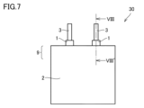
- FIG. 7 is a front view of the electricity accumulation device according to the third embodiment.
- FIG. 8 is a partial cross-sectional view taken along line VIII-VIII' in FIG.
- the present disclosure therefore aims to provide an adhesive film that has high adhesion to lead conductors when used in an electricity storage device.
- the adhesive film of the present disclosure is a first layer including a first major surface and a second major surface opposite the first major surface; a second layer provided on the second major surface, The first main surface is exposed to the outside, the first layer is an acid-modified polyolefin layer, the second layer is a heat-resistant resin layer,
- the first main surface includes a recess, In the first image, the area ratio of the recesses is 2.0% or more.
- an adhesive film that has high adhesion to lead conductors when used in an energy storage device.
- the area ratio of the recesses may be 2.0% or more and 20% or less.
- the adhesive film has high adhesion to the lead conductor and the material strength of the first layer is good.
- the average thickness of the first layer may be 20 ⁇ m or more and 200 ⁇ m or less. If the average thickness of the first layer is 20 ⁇ m or more, the first layer is less likely to be too thin and break, and good adhesion to the lead conductor can be ensured. If the average thickness of the first layer is 200 ⁇ m or less, the adhesive film can be made thin, and when the adhesive film is placed between the lead conductor and the sealed container and heat sealed, no unnecessary step is generated in the sealed portion.
- the acid-modified polyolefin layer may be an acid-modified polypropylene layer.
- the acid-modified polypropylene layer has excellent adhesion and sealing properties with metals. Therefore, an adhesive film in which the first layer is an acid-modified polypropylene layer has particularly excellent adhesion to lead conductors.
- the acid-modified polyolefin layer may contain at least one rubber selected from the group consisting of ethylene propylene rubber, ethylene butene rubber, ethylene octene rubber, and propylene butene rubber. These rubber components can be dispersed in small particles in the acid-modified polyolefin layer to form a sea-island structure. This allows the dispersed rubber components to alleviate residual stress generated when the adhesive film and the lead conductor are heat-sealed, further improving the adhesive strength between the adhesive film and the lead conductor.
- the heat-resistant resin layer may contain homopolypropylene. This allows the shape of the film to be maintained when the adhesive film and the lead conductor are heat-sealed.
- the adhesive film may be immersed in hexane at 40°C for 24 hours, and then the elastic modulus of the first main surface of the first layer may be measured using a nanoindenter at 25°C to be 600 MPa or more. This prevents the adhesive film from becoming too thin when it is adhered to the sealed container.
- the tab lead of the present disclosure is A lead conductor; and an adhesive film according to any one of (1) to (7) attached to a part of the lead conductor;
- the first layer of the adhesive film is a tab lead that is disposed in contact with the lead conductor.
- the adhesive film and the lead conductor are bonded with high adhesive strength.
- This tab lead is suitable for use in energy storage devices.
- the electricity storage device is a battery cell including a positive electrode, a negative electrode, and an electrolyte sandwiched between the positive electrode and the negative electrode; a lead conductor electrically connected to each of the positive electrode and the negative electrode; an enclosure that seals the battery cell; A portion of the lead conductor is exposed to the outside of the enclosure,
- the adhesive film according to any one of (1) to (7) above is disposed between the lead conductor and the sealed container; The first layer of the adhesive film is an electrical storage device that is placed in contact with the lead conductor.
- the adhesive film and the lead conductor are bonded with high adhesive strength. Therefore, the energy storage device can have excellent reliability.
- the electrolyte may be a solid electrolyte.
- the power storage device may have excellent reliability.
- the electrolyte may be a non-aqueous electrolyte.
- the electricity storage device may have excellent reliability.
- a ⁇ B means the upper and lower limits of a range (i.e., greater than or equal to A and less than or equal to B). If no unit is stated for A and only a unit is stated for B, the units of A and B are the same.
- any one numerical value listed as the lower limit and any one numerical value listed as the upper limit is also considered to be disclosed.
- a1 or more, b1 or more, and c1 or more are listed as the lower limit and a2 or less, b2 or less, and c2 or less are listed as the upper limit, a1 or more and a2 or less, a1 or more and b2 or less, a1 or more and c2 or less, b1 or more and a2 or less, b1 or more and b2 or less, b1 or more and c2 or less, c1 or more and a2 or less, c1 or more and b2 or less, and c1 or more and c2 or less are considered to be disclosed.
- the adhesive film 1 of embodiment 1 is an adhesive film 1 including a first layer 11 including a first main surface 11a and a second main surface 11b opposite to the first main surface 11a, and a second layer 12 provided on the second main surface 11b.
- the first main surface 11a is exposed to the outside.
- the first layer 11 is an acid-modified polyolefin layer.
- the second layer 12 is a heat-resistant resin layer.
- the first main surface 11a includes a recess.
- the area ratio of the recess is 2.0% or more.
- the adhesive film of embodiment 1 has high adhesive strength to the lead conductor when used in an electricity storage device. The reason for this is presumed to be as follows.
- the first layer of the adhesive film of embodiment 1 is an acid-modified polyolefin layer.
- the acid-modified polyolefin layer can be melted by heat during heat sealing between the adhesive film and the lead conductor, and has good adhesive strength to the lead conductor made of metal. Therefore, when the first layer of the adhesive film of embodiment 1 is placed in contact with the lead conductor and heat sealed, the adhesive film can have high adhesive strength to the lead conductor.
- the adhesive film and the lead conductor may shrink, generating stress, which may cause the adhesive film and the lead conductor to peel off.
- the first main surface includes a recess in a first image obtained by observing the first main surface at 10,000 times magnification using a scanning electron microscope after immersion in hexane at 40°C for 24 hours.
- the recess is presumably formed by the rubber component present on the first main surface of the first layer dissolving into hexane.
- the rubber component dissolving into hexane has a particularly low elastic modulus and a high stress relaxation effect. Therefore, peeling between the adhesive film and the lead conductor during cooling is suppressed, and the adhesive film can have high adhesive strength to the lead conductor.
- the first layer 11 has a first main surface 11a and a second main surface 11b, and the first main surface 11a is exposed to the outside.
- the first main surface 11a of the first layer 11 of the adhesive film 1 is a surface that is in contact with and adhered to a lead conductor in a tab lead or an electricity storage device.
- the first layer is an acid-modified polyolefin layer.
- the acid-modified polyolefin is a polyolefin containing an acid-modified group, which is modified with a carboxylic acid such as maleic acid, acrylic acid, methacrylic acid, or maleic anhydride.
- Examples of acid-modified polyolefin include maleic acid-modified polypropylene, acrylic acid-modified polypropylene, maleic anhydride-modified polypropylene, acrylic acid-modified polyethylene, maleic anhydride-modified polyethylene, and acrylic acid-modified ethylene acrylate. It is preferable that the first layer is an acid-modified polypropylene layer, since it has excellent adhesion and sealing properties with metals.
- the first layer is a maleic anhydride-modified polypropylene layer, since it has very excellent adhesion and sealing properties with metals.
- the acid-modified polyolefin layer may contain unmodified polyolefin as a resin component together with the acid-modified polyolefin, so long as it does not impair the effects of the present disclosure.
- acid-modified polyolefin and unmodified polyolefin are collectively referred to as polyolefin.
- the inclusion of the acid-modified group in the first layer can be confirmed by taking out only the first layer from the adhesive film and performing a transmission light analysis on the first layer using a Fourier transform infrared spectrophotometer.
- the acid-modified group include maleic acid, acrylic acid, methacrylic acid, and maleic anhydride.
- the content of the acid-modified group in the first layer can be 0.01% by mass or more and 1.0% by mass or less.
- the inclusion of the polyolefin in the first layer can be confirmed by taking out only the first layer from the adhesive film and performing a reflection light analysis on the first layer using a Fourier transform infrared spectrophotometer, or performing an analysis on the first layer using gas chromatography mass spectrometry.
- the first main surface After immersing the adhesive film of embodiment 1 in hexane at 40°C for 24 hours, the first main surface is observed at 10,000 times magnification using a scanning electron microscope (measurement conditions: accelerating voltage 2 kV, pretreatment: carbon coating) to obtain a first image, in which the first main surface includes recesses, and the area ratio of the recesses in the first image is 2.0% or more. This shows that the first layer has high adhesive strength to the lead conductor.
- the lower limit of the area ratio of the recesses is 2.0% or more, and may be 2.2% or more, 2.6% or more, 3.1% or more, 5.0% or more, or 7.0% or more, from the viewpoint of improving adhesive strength.
- the upper limit of the area ratio of the recesses may be 20% or less, or 15% or less, from the viewpoint of increasing the material strength of the first layer.
- the area ratio of the recesses may be 2.0% or more and 20% or less, 2.2% or more and 20% or less, 2.6% or more and 20% or less, 5.0% or more and 15% or less, or 7.0% or more and 15% or less.
- the area ratio of the recesses in the first image is measured by the following procedure.
- the adhesive film to be measured If the first layer of the adhesive film is adhered to the lead conductor and the first main surface of the first layer is not exposed to the outside, prepare an adhesive film with an exposed first main surface by immersing the adhesive film and lead conductor in an acid such as dilute hydrochloric acid to dissolve the lead conductor.
- an acid such as dilute hydrochloric acid to dissolve the lead conductor.
- the type of acid is selected appropriately according to the material of the lead conductor.
- the adhesive film to be measured is immersed in hexane at 40°C for 24 hours, then removed from the hexane and allowed to dry naturally.
- the first principal surface is observed at 10,000x magnification using a scanning electron microscope to obtain a first image.
- the first image is then binarized using the image processing software ImageJ (https://imagej.nih.gov/ij/index.html). Specifically, the first image is acquired as a grayscale image (JPEG) digital file and processed according to the binarization process procedure and parameters below, outputting pixels with a gradation above the threshold (bright) as 1 and pixels with a gradation below the threshold (dark) as 0. Pixels with a gradation below the threshold (dark) are defined as concaves.
- JPEG grayscale image
- a rectangular measurement field of 8 ⁇ m x 11 ⁇ m is set in the image after binarization processing.
- the percentage (S2/S1) x 100 of the area S2 of the recesses represented by pixels with a gradation below the threshold (dark) relative to the area S1 of the entire measurement field is calculated.
- the above percentage (S2/S1) x 100 is measured for the first image acquired in five non-overlapping regions.
- the average of the percentage (S2/S1) x 100 in the five measurement fields of view is calculated. In this disclosure, this average corresponds to the area ratio of the recesses in the first image.
- Figure 2 shows an image obtained by observing the first main surface of the adhesive film of embodiment 1 at 10,000x magnification using a scanning electron microscope after immersing it in hexane at 40°C for 24 hours, and then performing the above-mentioned binarization process using the image processing software ImageJ (https://imagej.nih.gov/ij/index.html).
- Figure 2 confirms that the first surface after immersion in hexane has recesses, which are shown as pixels with a gradation (dark) below the threshold.
- the adhesive film of embodiment 1 may have an elastic modulus of 600 MPa or more measured on the first main surface of the first layer at 25°C using a nanoindenter after immersing the film in hexane at 40°C for 24 hours. This prevents the adhesive film from becoming too thin when it is adhered to the sealed container.
- the modulus of elasticity of the first main surface of the first layer at 25°C is obtained by immersing the adhesive film in hexane at 40°C for 24 hours and then measuring the modulus of elasticity of the first main surface using a nanoindenter. The measurement of the modulus of elasticity is performed in an area of the first main surface where no recesses are formed.
- the nanoindenter used is a TriboIndenter TI980 manufactured by HYSITRON. In the nanoindenter, a regular triangular pyramid indenter (Berkovich indenter) with a diamond tip is used.
- the indenter is pressed vertically into the first main surface of the first layer under the following measurement conditions, a load-displacement curve is measured, and the modulus of elasticity is calculated.
- Indentation time 3 seconds
- Holding time 0 seconds
- Unloading time 0 seconds
- Loading speed 8 mN/second
- Indentation load 0.5 mN to 5 mN (adjust as appropriate so that the indentation size is about 10 ⁇ m to 20 ⁇ m).
- Time to reach indentation depth 5 seconds
- Time to hold load 0 seconds
- Time to remove indentation depth 5 seconds
- the acid-modified polyolefin layer may contain a rubber component. At least a portion of the rubber component is exposed on the first main surface of the first layer. At least a portion of the rubber component exposed on the first main surface dissolves in hexane at 40°C.
- the rubber component include ethylene propylene rubber, ethylene butene rubber, ethylene octene rubber, and propylene butene rubber.
- the acid-modified polyolefin layer may contain at least one selected from the group consisting of ethylene propylene rubber, ethylene butene rubber, ethylene octene rubber, and propylene butene rubber.
- ethylene propylene rubber is preferred because it has excellent dispersibility in acid-modified polyolefins, especially acid-modified polypropylene.
- the acid-modified polyolefin layer contains ethylene propylene rubber, the adhesive strength between the adhesive film and the lead conductor is further improved.
- the acid-modified polyolefin layer of embodiment 1 can be made of a polyolefin and a rubber component.
- the acid-modified polyolefin layer of embodiment 1 can contain impurities in addition to the polyolefin and rubber component as long as the effects of the present disclosure are not impaired.
- the rubber component content of the acid-modified polyolefin layer may be 5% by volume or more and 40% by volume or less, 10% by volume or more and 35% by volume or less, or 10% by volume or more and 30% by volume or less, from the viewpoint of suppressing peeling between the adhesive film and the lead conductor.
- the rubber component content means the total content of all rubbers.
- the rubber content of the acid-modified polyolefin layer is measured by the following procedure.
- the adhesive film is cut along an imaginary plane perpendicular to the first main surface to produce a slice in which the cross section of the acid-modified polyolefin layer is exposed.
- the slice is stained with a heavy metal (such as ruthenium tetroxide) and observed under a transmission microscope.
- a heavy metal such as ruthenium tetroxide
- the area percentage A (area %) of the stained portion relative to the area of the entire transmission microscope image is measured.
- the area percentage A (area %) is measured in five non-overlapping regions, and the average B (area %) of these area percentages A is calculated.
- the average B (area %) is regarded as the volume-based rubber content (volume %) of the acid-modified polyolefin layer.
- the melt flow rate of the rubber component in the acid-modified polyolefin layer may be 0.2 g/10 min or more and 30 g/10 min or less, or 1.8 g/10 min or more and 5.4 g/10 min or less. This makes it easier for the rubber component to be exposed to the first main surface of the first layer.
- the melt flow rate is measured in accordance with ISO 1133-1:2011. The measurement temperature is 230°C, and the load is 2.16 kg.
- the average thickness of the first layer may be 20 ⁇ m or more and 200 ⁇ m or less.
- the lower limit of the average thickness of the first layer may be 20 ⁇ m or more, 25 ⁇ m or more, or 30 ⁇ m or more, from the viewpoint of ensuring good adhesion to the lead conductor.
- the upper limit of the average thickness of the first layer may be 200 ⁇ m or less, 150 ⁇ m or less, 120 ⁇ m or less, or 100 ⁇ m or less, from the viewpoint of miniaturizing the power storage device including the adhesive film.
- the average thickness of the first layer may be 20 ⁇ m or more and 150 ⁇ m or less, 25 ⁇ m or more and 120 ⁇ m or less, or 30 ⁇ m or more and 100 ⁇ m or less.
- the method for measuring the average thickness of the first layer is as follows.
- the adhesive film is cut along the normal direction of the first main surface of the adhesive film using a microtome or the like to expose the cross section.
- the cross section is observed at 500x magnification using a digital microscope, and the thickness of the first layer is measured at five locations.
- the average of the thicknesses at the five locations is calculated. This average corresponds to the average thickness of the first layer.
- the average thicknesses of the second layer 12, other layers, and adhesive film described below are also measured in a similar manner.
- the first layer may contain various additives such as flame retardants, ultraviolet absorbers, light stabilizers, heat stabilizers, lubricants, colorants, etc.
- additives such as flame retardants, ultraviolet absorbers, light stabilizers, heat stabilizers, lubricants, colorants, etc.
- the types and amounts of these additives may be similar to those used in conventionally known acid-modified polyolefin layers.
- the second layer is a heat-resistant resin layer.
- the second layer functions as a support for the adhesive film.
- the second layer is disposed between the first layer and the enclosure in the electricity storage device.
- the heat-resistant resin constituting the second layer examples include polyolefin resins, polyethylene terephthalate, polyamide, and fluororesin. Among them, polyolefin resins are preferred because they have good adhesion to the acid-modified polyolefin layer constituting the first layer. Examples of polyolefin resins include polyethylene, polypropylene, ionomer resins, and acid-modified polyolefins.
- the second layer preferably contains homopolypropylene, which is a type of polypropylene, and more preferably is made of homopolypropylene.
- Homopolypropylene has a high function as a support because the thermocompression temperature can be adjusted so that it does not melt during thermocompression bonding between the adhesive film and the lead conductor.
- the heat-resistant resin constituting the second layer may be a crosslinked body crosslinked by irradiation with ionizing radiation such as accelerated electron beams or gamma rays.
- the heat-resistant resin constituting the second layer may be polypropylene with cross-linked bonds.
- Polypropylene with cross-linked bonds does not melt even when the temperature for thermocompression bonding between the adhesive film and the lead conductor is raised, and therefore functions well as a support.
- the heat-resistant resin constituting the second layer may be polyethylene naphthalate (PEN).
- PEN polyethylene naphthalate
- the heat-resistant resin constituting the second layer may be polyester, in which case the second layer may be a polyester nonwoven fabric.
- the average thickness of the second layer may be 20 ⁇ m or more and 150 ⁇ m or less, 30 ⁇ m or more and 120 ⁇ m or less, or 40 ⁇ m or more and 100 ⁇ m or less.
- the second layer may contain various additives such as flame retardants, ultraviolet absorbers, light stabilizers, heat stabilizers, lubricants, colorants, etc.
- additives such as flame retardants, ultraviolet absorbers, light stabilizers, heat stabilizers, lubricants, colorants, etc.
- the types and amounts of these additives may be the same as those used in conventionally known heat-resistant resin layers.
- the adhesive film of the first embodiment may include other layers in addition to the first layer and the second layer.
- the other layers include a layer (hereinafter also referred to as the "third layer") that plays a role in improving adhesion with an enclosure containing aluminum foil, and a layer (hereinafter also referred to as the "fourth layer”) that plays a role in trapping hydrofluoric acid that corrodes the lead conductor.
- the third layer is required to have strong adhesion with the enclosure of the electric storage device.
- the third layer is also polyolefin.
- the other layer may be one layer, or two or more layers may be combined. The position of the other layer is appropriately selected depending on the type of the other layer.
- the adhesive film 1 can include a first layer 11 including a first main surface 11a and a second main surface 11b opposite the first main surface 11a, a second layer 12 provided on the second main surface 11b, and a third layer 17 provided on the main surface of the second layer 12 opposite the main surface facing the first layer 11.
- the adhesive film 1 can include a first layer 11 including a first main surface 11a and a second main surface 11b opposite the first main surface 11a, a fourth layer 18 provided in contact with the second main surface 11b, and a second layer 12 provided on the main surface of the fourth layer 18 opposite the main surface facing the first layer 11.
- the adhesive film 1 can include a first layer 11 including a first main surface 11a and a second main surface 11b opposite the first main surface 11a, a fourth layer 18 provided in contact with the second main surface 11b, a second layer 12 provided on the main surface of the fourth layer 18 opposite the main surface facing the first layer 11, and a third layer 17 provided on the main surface of the second layer 12 opposite the main surface facing the fourth layer 18.
- the average thickness of the third layer may be 20 ⁇ m or more and 100 ⁇ m or less, 30 ⁇ m or more and 70 ⁇ m or less, or 35 ⁇ m or more and 60 ⁇ m or less.
- the average thickness of the fourth layer may be 20 ⁇ m or more and 100 ⁇ m or less, 30 ⁇ m or more and 70 ⁇ m or less, or 35 ⁇ m or more and 60 ⁇ m or less.
- the other layers may contain various additives such as flame retardants, ultraviolet absorbers, light stabilizers, heat stabilizers, lubricants, colorants, etc.
- additives such as flame retardants, ultraviolet absorbers, light stabilizers, heat stabilizers, lubricants, colorants, etc.
- the types and amounts of these additives may be similar to those used in other layers that are conventionally known.
- the lower limit of the average thickness of the adhesive film of embodiment 1 may be 40 ⁇ m or more, 50 ⁇ m or more, 70 ⁇ m or more, 80 ⁇ m or more, 100 ⁇ m or more, or 120 ⁇ m or more.
- the upper limit of the average thickness of the adhesive film may be 500 ⁇ m or less, 300 ⁇ m or less, or 250 ⁇ m or less.
- the average thickness may be 40 ⁇ m or more and 500 ⁇ m or less, 80 ⁇ m or more and 500 ⁇ m or less, 100 ⁇ m or more and 300 ⁇ m or less, or 120 ⁇ m or more and 250 ⁇ m or less.
- the adhesive film of embodiment 1 is produced, for example, by the following method.
- the raw materials for the first layer and the raw materials for the second layer are mixed using a known mixing device such as an open roll, a pressure kneader, a single-screw kneader, or a twin-screw kneader to obtain a mixed raw material.
- the mixed raw materials for the first and second layers can be extruded using a co-extrusion T-die extruder to obtain an adhesive film in which the first and second layers are laminated.
- the film formation conditions for the T-die extruder are, for example, a die lip opening of 0.3 to 1.0 mm and a take-up speed of 2 to 20 m/min.
- the thickness of the first layer after extrusion is adjusted to be 20 to 200 ⁇ m.
- the rubber component is more likely to be exposed on the first main surface of the first layer. For example, when the amount of rubber component is small, the higher the take-off speed, the more likely the rubber component is exposed on the first main surface. When the melt flow rate of the rubber component is small, the higher the take-off speed, the more likely the rubber component is exposed on the first main surface.
- the film-forming conditions in the T-die extruder for the first layer within the above range, the rubber component is exposed on the first main surface of the first layer, which can contribute to stress relaxation at the interface between the lead conductor and the adhesive film.
- the rubber component dissolves in hexane, making it possible to measure the amount of rubber component of the first layer present at the interface between the first layer and the lead conductor.
- the relationship between these film-forming conditions and the amount of rubber component exposed on the first main surface of the first layer was newly discovered by the present inventors.
- the present inventors developed the adhesive film of the present disclosure, focusing on the state of the surface in contact with the lead conductor, i.e., the first main surface of the first layer. Specifically, a predetermined amount or more of a rubber component that dissolves in hexane at 40° C. is present on the first main surface of the first layer made of an acid-modified polyolefin layer, thereby realizing high adhesion to the lead conductor of the first main surface.
- the rubber component that dissolves in hexane at 40° C. or higher has a particularly low elastic modulus and a high stress relaxation effect.
- the adhesive film of embodiment 1 and the lead conductor are suppressed from peeling due to stress generated during the cooling process.
- the present inventors have newly discovered that high adhesion to the lead conductor of the adhesive film can be realized by focusing on the ratio of the rubber component that dissolves in hexane at 40° C. that is present on the first main surface of the first layer.
- Patent Document 1 and Patent Document 2 disclose that the polyolefin layer arranged on the metal terminal (corresponding to the lead conductor) side of the adhesive film for metal terminals has a sea-island structure.
- the sea-island structure is observed in a cross section parallel to the TD and thickness direction of the polyolefin layer. Therefore, Patent Document 1 and Patent Document 2 do not disclose or suggest information regarding the state of the first main surface that contacts the lead conductor, which is the focus of attention in the adhesive film of the present disclosure.
- adhesion to the lead conductor the state of the first main surface that contacts the lead conductor is more important than the state of the cross section parallel to the TD and thickness direction of the polyolefin layer.
- the state of the cross section parallel to the TD and thickness direction of the polyolefin layer specified in Patent Document 1 and Patent Document 2 does not affect adhesion to the lead conductor.
- Patent Document 1 and Patent Document 2 the polyolefin layer is dyed with ruthenium tetroxide to observe the sea-island structure.
- the sea portion (sea part) and the island portion (island part) are dyed differently based on the difference in dyeing speed caused by the difference in crystallinity.
- the distinction between the sea portion and the island part by dyeing only shows that the crystallinity of the sea portion and the island part is different, and it is unclear whether the island parts in Patent Document 1 and Patent Document 2 are soluble in hexane. Therefore, the island parts shown in Figure 9 of Patent Document 1 and Figures 8 to 13 of Patent Document 2 do not show a rubber component that is soluble in hexane. Therefore, Patent Document 1 and Patent Document 2 do not disclose or suggest a rubber component that is soluble in hexane.
- FIG. 2 A tab lead according to an embodiment of the present disclosure (hereinafter also referred to as "embodiment 2") will be described with reference to Fig. 6.
- the tab lead of embodiment 2 includes a lead conductor 3 and the adhesive film of embodiment 1 attached to a part of the lead conductor 3.
- a first layer of the adhesive film is disposed in contact with the lead conductor 3.
- the adhesive film and the lead conductor are bonded with high adhesive strength. Therefore, the tab lead is particularly suitable for energy storage devices including all-solid-state batteries.
- metals such as aluminum, nickel, copper, and nickel-plated copper are used as the lead conductor.
- Aluminum is often used for the positive electrode, and aluminum, nickel, and nickel-plated copper for the negative electrode.
- a flat metal plate with a thickness of 50 ⁇ m to 2 mm, a width of 1 mm to 200 mm, and a length of 20 mm to 200 mm is preferably used.
- FIG. 7 is a front view that shows a schematic diagram of an embodiment of an electric storage device 30 according to Embodiment 3.
- Fig. 8 is a partial cross-sectional view taken along the line VIII-VIII' in Fig. 7.
- the electric storage device 30 according to Embodiment 3 includes a battery cell 15 including a positive electrode 10, a negative electrode 14, and an electrolyte 13 sandwiched between the positive electrode 10 and the negative electrode 14, a lead conductor 3 electrically connected to each of the positive electrode 10 and the negative electrode 14, and an enclosure 2 that seals the battery cell 15.
- a portion of the lead conductor 3 is exposed to the outside of the enclosure 2, and the adhesive film 1 according to Embodiment 1 is disposed between the lead conductor 3 and the enclosure 2.
- a first layer 11 of the adhesive film is disposed in contact with the lead conductor 3.
- the adhesive film 1 and the lead conductor 3 are bonded with high adhesive strength. Therefore, the electrolyte does not escape from the sealed container, and the electricity storage device has excellent reliability.
- the sealed container 2 is made of a laminate film 8 having a three-layer structure consisting of a metal layer 5 and a first resin layer 6 and a second resin layer 7 that cover the metal layer 5.
- the metal layer 5 is made of a metal such as aluminum foil.
- polyamide resins such as 6,6-nylon and 6-nylon, polyester resins, polyimide resins, etc. can be used.
- polyimide resins etc.
- the sealed container 2 is made by overlapping two laminate films 8 and heat-sealing the three sides other than the side through which the lead conductor 3 passes. At the outer periphery of the sealed container 2, the two metal layers 5 are bonded via the second resin layer 7.
- the lead conductor 3 is bonded (thermally fused) to the sealed container (laminate film) via the adhesive film 1 at the seal portion 9.
- a positive electrode 10, a negative electrode 14, and an electrolyte 13 are further enclosed inside the electric storage device 30.
- FIG. 8 shows a lead conductor connected to the negative electrode 14.
- a lead conductor connected to the positive electrode 10 is also present, but is not shown in FIG. 8.
- the electrolyte 13 may be a solid electrolyte. This maintains high adhesion of the adhesive film to the lead conductor 3 for a long period of time, further improving the reliability of the electric storage device 30.
- the electrolyte 13 may be a non-aqueous electrolyte.
- non-aqueous electrolytes examples include those obtained by dissolving fluorine-containing lithium salts such as LiPF 6 and LiBF 4 in diethyl carbonate (DEC), dimethyl carbonate (DMC), propylene carbonate (PC), or the like.
- DEC diethyl carbonate
- DMC dimethyl carbonate
- PC propylene carbonate
- the acid-modified polyolefin layer contains a rubber component, The acid-modified polyolefin layer may have a rubber component content of 5 vol % or more and 40 vol % or less. In the adhesive film of the present disclosure, the acid-modified polyolefin layer contains a rubber component, The acid-modified polyolefin layer may have a rubber component content of 10% by volume or more and 35% by volume or less. In the adhesive film of the present disclosure, the acid-modified polyolefin layer contains a rubber component, The acid-modified polyolefin layer may have a rubber component content of 10% by volume or more and 30% by volume or less.
- the content of acid-modified groups in the first layer may be 0.01% by mass or more and 1.0% by mass or less.
- Random PP Random polypropylene with a melting point of 139°C and a melt flow rate (MFR) of 5g/10min.
- Maleic anhydride modified random PP Maleic anhydride modified random polypropylene with a melting point of 157°C, MFR of 10g/10min and an acid modification rate of 1.2 mass%.
- the raw materials for the first layer were mixed in the mass ratios shown in Table 1 using a twin-screw kneader to obtain mixed raw materials PP32 to PP36.
- homopolypropylene hereinafter also referred to as "PP2" with a melting point of 166°C and MFR of 7g/10min was prepared.
- PP1 random PP with a melting point of 142°C and MFR of 6.7g/10min was prepared.
- the raw materials for the second and third layers were also kneaded using a twin-screw kneader.
- the raw materials for the first layer, second layer, and third layer were extruded using a co-extrusion T-die extruder to obtain adhesive films for each sample in which the first layer, second layer, and third layer were laminated in the above order.
- the film formation conditions were as shown in the "Film formation conditions" column in Table 2.
- the average thicknesses of the first layer, second layer, and third layer in the obtained adhesive film, and the average overall thickness of the adhesive film, were as shown in Table 2.
- the second and third layers were also immersed in hexane at 40°C for 24 hours, after which the elastic modulus of each surface was measured at 25°C using a nanoindenter. The results are shown in Table 2.
- the first layer of the adhesive film (length 10 mm, width 55 mm) of each sample was placed in contact with one main surface of the lead conductor and pressed at 210°C for 10 seconds to bond the first layer and the second layer to prepare a test sample.
- the conductor was cut at a position 10 mm from the end in the width direction, leaving the insulating film on the surface, and the conductor was folded, and the adhesive film was pulled in a 180° direction from the lead conductor to be peeled off, and the 180° peel strength was measured.
- the pulling speed was 100 mm/min.
- the measurement was performed 1 hour after adhesion.
- the results are shown in the "Peel Test" column in Table 2.
- an adhesive film is judged to have high adhesion to the lead conductor when the peel strength is 18 N/cm or more.
- the unit N/cm for peel strength represents the force (N) required to peel off a film 1 cm wide.
- the adhesive film of sample 1 corresponds to a comparative example. It was confirmed that the adhesive strength of the adhesive film for sample 1 to the lead conductor was insufficient. In sample 1, the area ratio of the recesses was less than 2.0%. This is presumably because the take-up speed during film formation was high compared to the amount of rubber component in the raw material for the first layer, making it difficult for the rubber component to appear on the first main surface of the first layer.
Landscapes
- Chemical & Material Sciences (AREA)
- Organic Chemistry (AREA)
- Engineering & Computer Science (AREA)
- Manufacturing & Machinery (AREA)
- Chemical Kinetics & Catalysis (AREA)
- Electrochemistry (AREA)
- General Chemical & Material Sciences (AREA)
- Adhesive Tapes (AREA)
Priority Applications (2)
| Application Number | Priority Date | Filing Date | Title |
|---|---|---|---|
| PCT/JP2023/027096 WO2025022540A1 (ja) | 2023-07-25 | 2023-07-25 | 接着性フィルム、タブリードおよび蓄電デバイス |
| JP2025535439A JPWO2025022540A1 (https=) | 2023-07-25 | 2023-07-25 |
Applications Claiming Priority (1)
| Application Number | Priority Date | Filing Date | Title |
|---|---|---|---|
| PCT/JP2023/027096 WO2025022540A1 (ja) | 2023-07-25 | 2023-07-25 | 接着性フィルム、タブリードおよび蓄電デバイス |
Publications (1)
| Publication Number | Publication Date |
|---|---|
| WO2025022540A1 true WO2025022540A1 (ja) | 2025-01-30 |
Family
ID=94374544
Family Applications (1)
| Application Number | Title | Priority Date | Filing Date |
|---|---|---|---|
| PCT/JP2023/027096 Pending WO2025022540A1 (ja) | 2023-07-25 | 2023-07-25 | 接着性フィルム、タブリードおよび蓄電デバイス |
Country Status (2)
| Country | Link |
|---|---|
| JP (1) | JPWO2025022540A1 (https=) |
| WO (1) | WO2025022540A1 (https=) |
Citations (5)
| Publication number | Priority date | Publication date | Assignee | Title |
|---|---|---|---|---|
| JP2013091702A (ja) * | 2011-10-25 | 2013-05-16 | Fujimori Kogyo Co Ltd | 接着性樹脂組成物、接着性樹脂成形体、及び接着性樹脂積層体 |
| JP2015170428A (ja) * | 2014-03-06 | 2015-09-28 | 昭和電工パッケージング株式会社 | タブ封止用絶縁フィルム及び電気化学デバイス |
| JP2019220295A (ja) * | 2018-06-18 | 2019-12-26 | 大倉工業株式会社 | タブリード用フィルム、及びこれを用いたタブリード |
| WO2021106576A1 (ja) * | 2019-11-29 | 2021-06-03 | 東洋紡株式会社 | ポリオレフィン系接着剤組成物及び積層体 |
| JP2023011363A (ja) * | 2021-07-12 | 2023-01-24 | 株式会社アイセロ | 熱可塑型接着フィルム |
Family Cites Families (2)
| Publication number | Priority date | Publication date | Assignee | Title |
|---|---|---|---|---|
| JP6706014B2 (ja) * | 2018-06-20 | 2020-06-03 | 大日本印刷株式会社 | 金属端子用接着性フィルム、接着性フィルム付き金属端子、及び電池 |
| WO2021090951A1 (ja) * | 2019-11-08 | 2021-05-14 | 大日本印刷株式会社 | 金属端子用接着性フィルム、金属端子用接着性フィルムの製造方法、金属端子用接着性フィルム付き金属端子、当該金属端子用接着性フィルムを用いた蓄電デバイス、及び蓄電デバイスの製造方法 |
-
2023
- 2023-07-25 WO PCT/JP2023/027096 patent/WO2025022540A1/ja active Pending
- 2023-07-25 JP JP2025535439A patent/JPWO2025022540A1/ja active Pending
Patent Citations (5)
| Publication number | Priority date | Publication date | Assignee | Title |
|---|---|---|---|---|
| JP2013091702A (ja) * | 2011-10-25 | 2013-05-16 | Fujimori Kogyo Co Ltd | 接着性樹脂組成物、接着性樹脂成形体、及び接着性樹脂積層体 |
| JP2015170428A (ja) * | 2014-03-06 | 2015-09-28 | 昭和電工パッケージング株式会社 | タブ封止用絶縁フィルム及び電気化学デバイス |
| JP2019220295A (ja) * | 2018-06-18 | 2019-12-26 | 大倉工業株式会社 | タブリード用フィルム、及びこれを用いたタブリード |
| WO2021106576A1 (ja) * | 2019-11-29 | 2021-06-03 | 東洋紡株式会社 | ポリオレフィン系接着剤組成物及び積層体 |
| JP2023011363A (ja) * | 2021-07-12 | 2023-01-24 | 株式会社アイセロ | 熱可塑型接着フィルム |
Also Published As
| Publication number | Publication date |
|---|---|
| JPWO2025022540A1 (https=) | 2025-01-30 |
Similar Documents
| Publication | Publication Date | Title |
|---|---|---|
| JP6146953B2 (ja) | 電池用外装材およびリチウム二次電池 | |
| CN112913054B (zh) | 负极用树脂集电体的制造方法、锂离子电池用负极的制造方法以及锂离子电池的制造方法 | |
| WO1997040539A1 (fr) | Cellules d'electrolyte anhydre | |
| WO1997040540A1 (fr) | Cellules d'electrolyte anhydre | |
| JP7775980B2 (ja) | 蓄電デバイス、バリア性フィルム、蓋ユニット、蓋ユニットの製造方法 | |
| JP7354348B1 (ja) | 非水電解質電池用タブリード | |
| EP4366051A1 (en) | Tab sealant and power storage device using same | |
| WO2025022540A1 (ja) | 接着性フィルム、タブリードおよび蓄電デバイス | |
| WO2025022541A1 (ja) | 接着性フィルム、タブリードおよび蓄電デバイス | |
| JP7354346B1 (ja) | 非水電解質電池用タブリード | |
| JP7768067B2 (ja) | 非水電解質電池用リード線、絶縁膜及び非水電解質電池 | |
| JP2025109997A (ja) | 絶縁フィルム、リード線および非水電解質電池 | |
| KR100879466B1 (ko) | 전극조립체 수납용 파우치형 용기 | |
| JP7354347B1 (ja) | 非水電解質電池用タブリード | |
| EP4517955A1 (en) | Adhesive film for metal terminals and method for producing same, metal terminal provided with adhesive film for metal terminals, outer package material for power storage devices, kit comprising outer package material for power storage devices and adhesive film for metal terminals, and power storage device and method for producing same | |
| JP7794209B2 (ja) | リード線および電力貯蔵デバイス | |
| EP4517954A1 (en) | Adhesive film for metal terminals and method for producing same, metal terminal provided with adhesive film for metal terminals, outer package material for power storage devices, kit comprising outer package material for power storage devices and adhesive film for metal terminals, and power storage device and method for producing same | |
| JP2003297336A (ja) | 正極用リード及びこれを用いた電力貯蔵デバイス | |
| JP7354345B1 (ja) | 非水電解質電池用タブリード | |
| KR102950106B1 (ko) | 봉지 필름, 전극 리드선 부재, 및 전지 | |
| EP4661172A1 (en) | Sealing film, metal terminal, battery, and device | |
| WO2019097877A1 (ja) | 樹脂成形体およびタブリード | |
| WO2025046646A1 (ja) | リード線および蓄電デバイス | |
| WO2023153301A1 (ja) | 非水電解質電池用リード線、絶縁膜及び非水電解質電池 | |
| WO2026009484A1 (ja) | リード導体および非水電解質電池 |
Legal Events
| Date | Code | Title | Description |
|---|---|---|---|
| 121 | Ep: the epo has been informed by wipo that ep was designated in this application |
Ref document number: 23946624 Country of ref document: EP Kind code of ref document: A1 |
|
| ENP | Entry into the national phase |
Ref document number: 2025535439 Country of ref document: JP Kind code of ref document: A |
|
| NENP | Non-entry into the national phase |
Ref country code: DE |