WO2025018396A1 - ばね部材 - Google Patents
ばね部材 Download PDFInfo
- Publication number
- WO2025018396A1 WO2025018396A1 PCT/JP2024/025836 JP2024025836W WO2025018396A1 WO 2025018396 A1 WO2025018396 A1 WO 2025018396A1 JP 2024025836 W JP2024025836 W JP 2024025836W WO 2025018396 A1 WO2025018396 A1 WO 2025018396A1
- Authority
- WO
- WIPO (PCT)
- Prior art keywords
- disc springs
- connecting portion
- disc
- spring member
- spring
- Prior art date
- Legal status (The legal status is an assumption and is not a legal conclusion. Google has not performed a legal analysis and makes no representation as to the accuracy of the status listed.)
- Pending
Links
Images








Classifications
-
- F—MECHANICAL ENGINEERING; LIGHTING; HEATING; WEAPONS; BLASTING
- F16—ENGINEERING ELEMENTS AND UNITS; GENERAL MEASURES FOR PRODUCING AND MAINTAINING EFFECTIVE FUNCTIONING OF MACHINES OR INSTALLATIONS; THERMAL INSULATION IN GENERAL
- F16F—SPRINGS; SHOCK-ABSORBERS; MEANS FOR DAMPING VIBRATION
- F16F1/00—Springs
- F16F1/02—Springs made of steel or other material having low internal friction; Wound, torsion, leaf, cup, ring or the like springs, the material of the spring not being relevant
- F16F1/32—Belleville-type springs
Definitions
- the present invention relates to a spring member.
- a spring member is known that is placed between a first pressed body and a second pressed body and applies pressure to one or both of them.
- Spring members are used in a variety of devices.
- a spring member fixes a semiconductor module to a cooling member that dissipates heat generated in the semiconductor module to the outside (see, for example, Patent Document 1).
- the spring member described in Patent Document 1 includes a plurality of disc springs and a support portion that supports the plurality of disc springs.
- the support portion includes a base portion and a plurality of connecting portions that each extend from the base portion and connect the base portion and the disc springs. In this case, the connecting portions connect the disc springs over the shortest distance.
- a spring member having multiple disc springs has nonlinear load characteristics and is required to press evenly against the object being pressed.
- the length of the connecting portion connecting the disc springs becomes shorter. If the connecting portion is short, the stress applied to the connecting portion when a load is applied to the spring member becomes more concentrated, which may cause the connecting portion to break.
- the disc springs are brought closer together, the stress applied to the connecting portion is suppressed, but the number of disc springs per unit area decreases, which may make it impossible to evenly press against the object being pressed.
- the present invention was made in consideration of the above, and aims to provide a spring member that can press an object with a uniform pressure load while mitigating the stress applied to the connecting portion.
- the spring member of the present invention comprises a plurality of hollow frustum-shaped disc springs and a first connecting portion that connects two disc springs that form a pair among the plurality of disc springs, and the first connecting portion extends along a plane on which the outer edges of the two disc springs that form the pair are located and is partially bent.
- the spring member according to the present invention is characterized in that, in the above invention, the first connecting portion has a first straight portion that extends on a straight line passing through the center of one of the pair of disc springs and the extending end of the one disc spring at the first connecting portion, and a second straight portion that extends on a straight line passing through the center of the other of the pair of disc springs and the extending end of the other disc spring at the first connecting portion.
- the spring member according to the present invention is characterized in that, in the above invention, the plurality of disc springs are arranged in two directions that intersect with each other, and the plurality of disc springs are all connected via the plurality of first connecting parts.
- the spring member according to the present invention is characterized in that, in the above invention, the plurality of disc springs are arranged in two directions that intersect with each other, and the plurality of disc springs and the plurality of first connecting parts form a closed ring.
- the spring member according to the present invention is also characterized in that, in the above invention, the multiple disc springs are arranged concentrically or in a spiral shape.
- the spring member according to the present invention is characterized in that, in the above invention, it further comprises a frame-shaped base and a second connecting portion that connects the disc springs and the base, and the base surrounds the plurality of disc springs and the first connecting portion.
- the spring member according to the present invention is characterized in that, in the above invention, the first connecting portion is connected to the outer edge of the disc spring, and the direction in which the first connecting portion extends from the outer edge is perpendicular to the tangent of the outer edge at the portion from which the first connecting portion extends.
- the present invention has the effect of being able to apply a uniform pressure load to an object while reducing the stress applied to the connection.
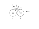
- FIG. 1 is a plan view showing a schematic configuration of a spring member according to a first embodiment of the present invention.
- FIG. 2 corresponds to a side view taken along the direction of the arrow A in FIG. 1, and shows an example of the shape of the spring member when a load is applied thereto.
- FIG. 3 is a plan view showing a schematic example of the configuration of a conventional spring member.
- FIG. 4 corresponds to a side view taken along the direction of the arrow B in FIG. 3, and shows an example of the shape of the spring member when a load is applied thereto.
- FIG. 5 is a plan view showing a configuration of a spring member according to a first modification of the first embodiment of the present invention.
- FIG. 1 is a plan view showing a schematic configuration of a spring member according to a first embodiment of the present invention.
- FIG. 2 corresponds to a side view taken along the direction of the arrow A in FIG. 1, and shows an example of the shape of the spring member when a load is applied thereto.
- FIG. 6 is a plan view showing a configuration of a spring member according to a second modification of the first embodiment of the present invention.
- FIG. 7 is a plan view showing a configuration of a spring member according to a third modification of the first embodiment of the present invention.
- FIG. 8 is a plan view showing a configuration of a spring member according to the second embodiment of the present invention.
- FIG. 9 is a plan view showing a configuration of a spring member according to a third embodiment of the present invention.
- FIG. 10 is a plan view showing a configuration of a main part of a spring member according to a first modification of the third embodiment of the present invention.
- FIG. 11 is a plan view showing a configuration of a main part of a spring member according to a second modification of the third embodiment of the present invention.
- FIG. 12 is a plan view showing a configuration of a main part of a spring member according to a fourth embodiment of the present invention.
- FIG. 13 is a plan view showing a configuration of a main part of a spring member according to a fifth embodiment of the present invention.
- FIG. 14 is a plan view showing a configuration of a main part of a spring member according to a sixth embodiment of the present invention.
- FIG. 15 is a plan view showing a configuration of a main part of a spring member according to a seventh embodiment of the present invention.
- FIG. 16 is a plan view showing a configuration of a main part of a spring member according to an eighth embodiment of the present invention.
- FIG. 17 is a plan view showing a configuration of a main part of a spring member according to a ninth embodiment of the present invention.
- (Embodiment 1) 1 is a plan view showing a schematic configuration of a spring member according to a first embodiment of the present invention.
- the spring member 1 according to the first embodiment applies pressure to both a first pressed body and a second pressed body by elastic force.
- the spring member 1 is formed using flat spring steel.
- the spring member 1 is formed by punching out the outer shape of the spring member 1 from flat spring steel.
- spring steel include, but are not limited to, carbon tool steel (SK material) and stainless steel (SUS).
- the spring member 1 comprises two disc springs 2 and a connecting portion (first connecting portion) 3 that connects the disc springs 2.
- the disc spring 2 is in the shape of a hollow truncated cone (frustum cone) having an inclined surface that is inclined from the outer periphery toward the center.
- the disc spring 2 has a circular outer shape, and a through hole with a circular opening is formed in the center. This through hole forms a hole shape that spreads from the center toward the outer periphery.
- the disc spring 2 has, for example, a uniform plate thickness and a shape that spreads radially.
- the disc spring 2 is formed by molding a hollow disc-shaped member so that it rises continuously from the outer periphery toward the inner periphery.
- the two disc springs 2 are arranged on the same plane with their penetrating directions aligned.
- Each disc spring 2 is convex in a direction perpendicular to the arrangement direction.
- a slit may be formed in the disc spring 2. This slit may be formed on either the inner circumferential side or the outer circumferential side. When the slit is formed on the outer circumferential side, it is disposed in a part other than the connecting portion of the connecting portion 3.
- the connecting portion 3 is strip-shaped and connects the two disc springs 2.
- the connecting portion 3 has, for example, the same thickness as the thickness of the disc spring 2.
- the thickness of the disc spring 2 corresponds to the distance between the front and back surfaces of the disc spring 2.
- the connecting portion 3 extends from an end of one of the disc springs 2 along the radial direction of a circle formed by the outer edges of the disc spring 2, and then bends to extend along the radial direction of the circle formed by the outer edges of the other disc spring 2, and connects to the outer edge of the other disc spring 2. That is, the connecting portion 3 extends with a bent portion, and the two disc springs 2 are connected at both ends.
- the connecting portion 3 also extends along a plane on which the outer edges of the disc springs 2 to be connected are located. The outer edges of the two disc springs 2 that make up a pair are included in this plane, and the connecting portion 3 may be separated in a direction perpendicular to the plane within the range of manufacturing tolerance.
- the connecting portion 3 may be configured to be connected to the inner periphery side of the outer edge of the disc spring 2 .
- the connecting portion 3 is composed of a first straight portion 31 extending on a straight line L1 passing through the center of one of the two disc springs 2 in the pair and the extending end from the one disc spring 2 in the connecting portion 3, and a second straight portion 32 extending on a straight line L2 passing through the center of the other disc spring 2 in the two disc springs 2 in the pair and the extending end from the other disc spring 2 in the connecting portion 3.
- the straight lines L1 and L2 correspond to the direction in which the connecting portion 3 extends from the outer edge of the disc spring 2. This extending direction is perpendicular to the tangent of the outer edge of the disc spring 2 at the portion from which the connecting portion 3 extends.
- the connecting portion 3 will be described with reference to an example in which the above-mentioned straight lines L1 and L2 pass through the center of the disc spring 2, but it is possible for the straight lines L1 and L2 to be configured not to pass through the center of the disc spring 2.
- the direction in which the connecting portion 3 extends from the outer edge of the disc spring 2 may be in a direction that is not perpendicular to the tangent to the outer edge of the disc spring 2. In this case, by making the extension direction of the connecting portion 3 perpendicular (90°) to the tangent, the angles formed by the connecting portion 3 and each disc spring 2 connected to it are each 90°, and stress bias can be suppressed.
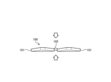
- Figure 2 corresponds to a side view of Figure 1 taken along the direction of arrow A, and shows an example of the shape of the spring member when a load is applied.
- the disc spring 2 deforms in a direction that reduces the height of the truncated cone (the distance between one end and the other end in the penetration direction).
- a bending stress is applied to the connecting portion 3, and curling occurs. The occurrence of this curling reduces the load applied to the connecting portion 3 by the bending stress.
- FIG. 3 is a plan view showing a schematic example of the configuration of a conventional spring member.
- Conventional spring member 100 comprises two disc springs 101 and a connecting portion 102 that connects the two disc springs 101.
- Disc spring 101 has a shape similar to that of disc spring 2.
- Connecting portion 102 extends linearly, and the two disc springs 101 are connected at both ends.
- Connecting portion 102 connects the two disc springs 101 over the shortest distance.
- Figure 4 corresponds to a side view of Figure 3 taken along the line B, and shows an example of the shape of the spring member when a load is applied.
- Figure 2 when a load is applied to the disc spring 101, the disc spring 101 deforms in a direction that reduces the height of the truncated cone. At this time, only bending stress is applied to the connecting portion 102, and no curling occurs. For this reason, a large load due to bending stress is applied to the connecting portion 102, which deforms it and may cause damage, etc.
- the connecting parts 3 connecting the disc springs 2 to each other are formed with a partially bent shape, which increases the number of disc springs 2 per unit area while reducing the bending stress applied to the connecting parts 3 when a load is applied to the spring member 1.
- the spring member can press an object with a uniform pressure load while mitigating the stress applied to the connecting parts.
- Fig. 5 is a plan view showing the configuration of a spring member according to the first modification of the first embodiment of the present invention.
- a connecting portion 3A is provided instead of the connecting portion 3 of the spring member 1 according to the first embodiment.
- the spring member 1A in this modified example 1 includes two disc springs 2 and a connecting portion (first connecting portion) 3A that connects the disc springs 2.
- the connecting portion 3A is band-shaped and connects the two disc springs 2.
- the connecting portion 3A extends from the outer edge of one of the disc springs 2, bends in an arc, and connects to the outer edge of the other disc spring 2. At this time, the connecting portion 3A bends so that it is convex on the opposite side of the line segment connecting the centers of the disc springs 2.
- the connecting portion 3A is also disposed on the plane on which the outer edges of the disc springs 2 are located. In other words, the connecting portion 3A bends in part and extends, and the two disc springs 2 are connected at both ends.
- the connecting portions 3A connecting the disc springs 2 to each other are formed with a partially bent shape, thereby increasing the number of disc springs 2 per unit area while reducing the bending stress applied to the connecting portions 3A when a load is applied to the spring member 1A.
- the spring member can press an object with a uniform pressure load while mitigating the stress applied to the connecting portions.
- Fig. 6 is a plan view showing the configuration of a spring member according to the second modification of the first embodiment of the present invention.
- a connecting portion 3B is provided instead of the connecting portion 3 of the spring member 1 according to the first embodiment.
- the spring member 1B in this modified example 2 includes two disc springs 2 and a connecting portion (first connecting portion) 3B that connects the disc springs 2.
- the connecting portion 3B is belt-shaped and connects the two disc springs 2.
- the connecting portion 3B extends from the outer edge of one of the disc springs 2, bends in an arc, and connects to the outer edge of the other disc spring 2. At this time, the connecting portion 3B bends so as to be convex on the opposite side of the line segment connecting the centers of the disc springs 2.
- the connecting portion 3B is also disposed on a plane on which the outer edges of the disc springs 2 are located. In other words, the connecting portion 3B extends while being partially bent, and the two disc springs 2 are connected at both ends.
- the connecting portion 3B has a shape that follows a circle L (an ellipse in FIG. 6) that passes through the center of each of the disc springs 2 in a plan view seen from the height (axis) direction of the frustum shape.
- the connecting portion 3B connecting the disc springs 2 to each other has a partially bent shape, which increases the number of disc springs 2 per unit area while reducing the bending stress applied to the connecting portion 3B when a load is applied to the spring member 1B.
- the spring member can press an object with a uniform pressure load while mitigating the stress applied to the connecting portion.
- the installation space for the connecting portion 3B can be made smaller than in the V-shaped configuration in which straight lines are connected, such as the connecting portion 3 in embodiment 1.
- Fig. 7 is a plan view showing the configuration of a spring member according to the third modification of the first embodiment of the present invention.
- a connecting portion 3C is provided instead of the connecting portion 3 of the spring member 1 according to the first embodiment.
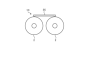
- the spring member 1C in this modified example 3 includes two disc springs 2 and a connecting portion (first connecting portion) 3C that connects the disc springs 2.
- the connecting portion 3C is belt-shaped and connects the two disc springs 2.
- the connecting portion 3C extends radially from the outer edge of one of the disc springs 2, then bends at a right angle toward the other disc spring 2 and extends, and then bends at a right angle toward the other disc spring 2 to connect to the outer edge of the other disc spring 2.
- the connecting portion 3C is disposed on a plane on which the outer edges of the disc springs 2 are located. In other words, the connecting portion 3C extends with a portion bent, and the two disc springs 2 are connected at both ends.
- FIG. 7 shows an example in which the connecting portion 3C is bent at a right angle, it may be bent at an angle other than a right angle.
- the connecting portion 3C connecting the disc springs 2 to each other has a partially bent shape, which increases the number of disc springs 2 per unit area while reducing the bending stress applied to the connecting portion 3C when a load is applied to the spring member 1C.
- the spring member can press an object with a uniform pressure load while mitigating the stress applied to the connecting portion.
- Fig. 8 is a plan view showing the configuration of a spring member according to the second embodiment of the present invention.
- six disc springs 2 and a plurality of connecting parts are provided in addition to the spring member 1 according to the first embodiment.
- the parts that are different from the first embodiment will be described, and the same components will be given the same reference numerals and the description will be omitted.
- the spring member 1D includes six disc springs 2 and connecting portions (first connecting portions) 3, 3D that connect adjacent disc springs 2.
- the six disc springs 2 are arranged in two directions that intersect with each other.
- the six disc springs 2 are arranged in a staggered manner.
- the left-right direction is defined as the row direction
- the up-down direction is defined as the column direction in the arrangement of the disc springs 2.
- the connecting portion 3 is belt-shaped and connects adjacent disc springs 2 in the row direction among the six disc springs 2.
- a plurality of connecting portions 3 are provided, and for example, when the plurality of disc springs 2 are arranged in a 2 ⁇ 3 matrix, the disc spring 2 located in the first row, second column is connected to the disc spring 2 located in the first row, first column via the connecting portion 3, and also connected to the disc spring 2 located in the first row, third column via a connecting portion 3 different from the disc spring 2 located in the first row, first column.
- a connecting portion 3 is provided on the outer side opposite to the adjacent disc springs 2 between the rows of disc springs 2.
- the connecting portion 3D is belt-shaped and connects adjacent disc springs 2 in the row direction among the six disc springs 2. Like the connecting portion 3, the connecting portion 3D is partially bent and extends, and is connected to two disc springs 2 at both ends. In the second embodiment, all the disc springs 2 are connected via the connecting portions 3, 3D.
- the connecting portions 3, 3D connecting the disc springs 2 to each other are formed with a partially bent shape, thereby increasing the number of disc springs 2 per unit area while reducing the bending stress applied to the connecting portions 3, 3D when a load is applied to the spring member 1D.
- the spring member can press an object with a uniform pressure load while mitigating the stress applied to the connecting portions.
- Fig. 9 is a plan view showing the configuration of a spring member according to the third embodiment of the present invention.
- nine disc springs 2 and a plurality of connecting parts are provided in addition to the spring member 1 according to the first embodiment.
- the parts that are different from the first embodiment will be described, and the same components will be given the same reference numerals and the description will be omitted.
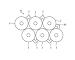
- the spring member 1E in this embodiment 3 includes nine disc springs 2 and connecting portions (first connecting portions) 3, 3E that connect adjacent disc springs 2 to each other.
- the connecting portion 3 connects adjacent disc springs 2 in the row direction among the nine disc springs 2.
- a plurality of connecting portions 3 are provided, and for example, when the plurality of disc springs 2 are arranged in a 3 ⁇ 3 matrix as shown in Fig. 9, the disc spring 2 located in the first row, second column is connected to the disc spring 2 located in the first row, first column via the connecting portion 3, and also connected to the disc spring 2 located in the first row, third column via a connecting portion 3 different from the connecting portion 3 connected to the disc spring 2 located in the first row, first column.
- the connecting portion 3 is provided so that the disc spring 2 in the nth row protrudes toward the space between the disc springs 2 in the (n-1)th row.
- the connecting portion 3E is band-shaped and connects adjacent disc springs 2 in the column direction among the nine disc springs 2. Like the connecting portion 3, the connecting portion 3E is partially bent and extends, and connects to two disc springs 2 at both ends. In this embodiment 3, two connecting portions 3E are provided. When the multiple disc springs 2 are arranged in a 3x3 matrix as shown in FIG. 9, one connecting portion 3E connects the disc spring 2 located in the first row and third column to the disc spring 2 located in the second row and third column. The other connecting portion 3E connects the disc spring 2 located in the second row and first column to the disc spring 2 located in the third row and first column.
- the connecting portions 3, 3E connecting the disc springs 2 to each other are formed with a partially bent shape, thereby increasing the number of disc springs 2 per unit area while reducing the bending stress applied to the connecting portions 3, 3E when a load is applied to the spring member 1E.
- the spring member can press an object with a uniform pressing load while mitigating the stress applied to the connecting portions.
- Fig. 10 is a plan view showing a configuration of a main part of a spring member according to a first modified example of the third embodiment of the present invention.
- a connecting part (first connecting part) 3F is provided instead of the connecting part 3 of the spring member 1E according to the third embodiment.
- the connecting portion 3F in this modified example 1 is band-shaped and connects two disc springs 2.
- the connecting portion 3F extends from the outer edge of one disc spring 2, then bends toward the other disc spring 2 and connects to the outer edge of the other disc spring 2.
- the connecting portions 3E, 3F that connect the disc springs 2 to each other are partially bent, thereby increasing the number of disc springs 2 per unit area while reducing the bending stress applied to the connecting portions 3E, 3F when a load is applied to the spring member.
- the spring member can press an object with a uniform pressure load while mitigating the stress applied to the connecting portions.
- the connecting portion 3F is bent so as to fit between the disc springs 2 in adjacent rows, so that the length of the connecting portion 3F can be secured within the space formed by the multiple disc springs.
- the extension length of the connecting portion 3F can be made longer than that of the connecting portion 3, and the bending stress can be further reduced.
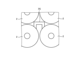
- Fig. 11 is a plan view showing the configuration of the main part of a spring member according to a second modification of the third embodiment of the present invention.
- a connecting part (first connecting part) 3G is provided instead of the connecting part 3 of the spring member 1E according to the third embodiment.
- the connecting portion 3G in this second modified example is strip-shaped and connects two disc springs 2.
- the connecting portion 3G extends in the column direction from the outer edge of one of the disc springs 2, then bends in the row direction, and then bends in the column direction to connect to the outer edge of the other disc spring 2.
- the connecting portion 3G is U-shaped and bent at a right angle.
- FIG. 11 shows an example in which the connecting portion 3G is bent at a right angle, it may be bent at an angle other than a right angle.
- the connecting portions 3E, 3G that connect the disc springs 2 to each other are partially bent, thereby increasing the number of disc springs 2 per unit area while reducing the bending stress applied to the connecting portions 3E, 3G when a load is applied to the spring member.
- the spring member can press an object with a uniform pressure load while mitigating the stress applied to the connecting portions.
- Fig. 12 is a plan view showing the configuration of a spring member according to the fourth embodiment of the present invention.
- nine disc springs 2 and a plurality of connecting parts are provided in addition to the spring member 1 according to the first embodiment.
- the parts that are different from the first embodiment will be described, and the same components will be given the same reference numerals and the description will be omitted.
- the spring member 1F in this fourth embodiment includes nine disc springs 2 and connecting portions (first connecting portions) 3H, 3I that connect adjacent disc springs 2.
- the nine disc springs 2 are arranged in a 3x3 array, and the disc spring 2 located in the center (second row, second column) is connected to the disc springs 2 located around it via one of the connecting portions 3H, 3I.
- the connecting portion 3H connects the disc spring 2 located in the center to the disc spring 2 located at a corner among the nine disc springs 2.
- a portion of the connecting portion 3H is bent to form an arc shape, and connects to each of the two disc springs 2 at both ends.
- a plurality of connecting portions 3H are provided, and for example, one connects the disc spring 2 located in the center to the disc spring 2 located in the first row and first column (top left of Figure 12).
- the connecting portion 3H also connects the disc spring 2 located in the center to the disc spring 2 located in the first row and third column (top right of Figure 12), the disc spring 2 located in the third row and first column (bottom left of Figure 12), and the disc spring 2 located in the third row and third column (bottom right of Figure 12).
- the connecting portion 3I connects the disc spring 2 located in the center out of the nine disc springs 2 to the disc springs 2 located other than at the corners. Like the connecting portion 3, the connecting portion 3I is partially bent and extends, and connects to two disc springs 2 at both ends. There are multiple connecting portions 3I, and for example, one connects the disc spring 2 located in the center to the disc spring 2 located in the first row and second column (top center of Figure 14). The connecting portion 3I also connects the disc spring 2 located in the center to the disc spring 2 located in the second row and first column (center left of Figure 14), the disc spring 2 located in the second row and third column (center right of Figure 14), and the disc spring 2 located in the third row and second column (center bottom of Figure 14).
- the connecting portions 3H, 3I that connect the disc springs 2 to each other are partially bent, thereby increasing the number of disc springs 2 per unit area while reducing the bending stress applied to the connecting portions 3H, 3I when a load is applied to the spring member 1F.
- the spring member can press an object with a uniform pressure load while mitigating the stress applied to the connecting portions.
- Fig. 13 is a plan view showing the configuration of a spring member according to the fifth embodiment of the present invention.
- a connecting portion 3J is further provided in addition to the spring member 1D according to the second embodiment. The following describes the parts that are different from the second embodiment, and the same components are given the same reference numerals and the description thereof will be omitted.
- the spring member 1G in this fifth embodiment includes six disc springs 2 and connecting portions (first connecting portions) 3, 3D, and 3J that connect adjacent disc springs 2 to each other.
- the connecting portion 3J is belt-shaped and connects adjacent disc springs 2 in the row direction among the six disc springs 2, which are different from the disc springs 2 connected by the connecting portion 3D. Similar to the connecting portions 3 and 3D, the connecting portion 3J is partially bent and extends, and is connected to two disc springs 2 at both ends, respectively.
- the spring member 1G forms a closed loop shape with the disc spring 2 and the connecting portions 3, 3D, and 3J.
- the connecting portions 3, 3D, 3J that connect the disc springs 2 to each other are formed with a partially bent shape, thereby increasing the number of disc springs 2 per unit area while reducing the bending stress applied to the connecting portions 3, 3D, 3J when a load is applied to the spring member 1G.
- the spring member can press an object with a uniform pressing load while mitigating the stress applied to the connecting portions.
- the spring member 1G forms a closed annular shape with the disc spring 2 and the connecting portions 3, 3D, and 3J, so that the relative positional relationship of the disc spring 2 can be maintained compared to the spring member 1D.
- Fig. 14 is a plan view showing the configuration of a spring member according to the sixth embodiment of the present invention.
- a connecting portion 3K is further provided in addition to the spring member 1E according to the third embodiment.
- the spring member 1H in this sixth embodiment includes nine disc springs 2 and connecting portions (first connecting portions) 3, 3E, and 3K that connect adjacent disc springs 2 to each other.
- the connecting portion 3K is belt-shaped and connects adjacent disc springs 2 in the row direction among the nine disc springs 2, which are different from the disc springs 2 connected by the connecting portion 3E. Like the connecting portions 3 and 3E, the connecting portion 3K is partially bent and extends, and is connected to two disc springs 2 at both ends, respectively.
- the spring member 1H forms a closed ring shape by the disc spring 2 and the connecting portions 3, 3E, and 3K.
- the connecting portions 3, 3E, and 3K that connect the disc springs 2 to each other are formed with a partially bent shape, thereby increasing the number of disc springs 2 per unit area while reducing the bending stress applied to the connecting portions 3, 3E, and 3K when a load is applied to the spring member 1H.
- the spring member can press an object with a uniform pressing load while mitigating the stress applied to the connecting portions.
- the spring member 1H is formed into a closed ring shape by the disc spring 2 and the connecting portions 3, 3E, and 3K, so that the relative positional relationship of the disc spring 2 can be maintained compared to the spring member 1E.
- Fig. 15 is a plan view showing the configuration of a spring member according to the seventh embodiment of the present invention.
- twenty-four disc springs 2 and a plurality of connecting portions 3, 3L are provided in addition to the spring member 1 according to the first embodiment.
- the parts that are different from the first embodiment will be described, and the same components will be given the same reference numerals and will not be described.
- the spring member 1I in this seventh embodiment comprises twenty-four disc springs 2 and connecting portions (first connecting portions) 3, 3L that connect adjacent disc springs 2 to each other.
- the twenty-four disc springs 2 form a triple ring structure that is arranged on the circumference of a concentric circle formed by an inner periphery, an outer periphery, and an intermediate portion.
- Four disc springs 2 are arranged on the inner periphery, eight on the intermediate portion, and twelve on the outer periphery, and in each portion, they are arranged at equal intervals, for example, in the circumferential direction.
- the connecting portions 3 connect adjacent disc springs 2 in the circumferential direction of each section among the multiple disc springs 2.
- a plurality of connecting portions 3 are provided, and for example, the disc springs 2 located on the outer periphery are connected to adjacent disc springs 2 on one side in the circumferential direction via connecting portions 3, and are also connected to adjacent disc springs 2 on the other side in the circumferential direction via connecting portions 3 different from the connecting portions 3 that connect to the disc springs 2 on one side.
- the connecting portion 3L is band-shaped and connects adjacent disc springs 2 of annular structure among the multiple disc springs 2. Like the connecting portion 3, the connecting portion 3L is partially bent and extends, and connects to two disc springs 2 at both ends. In the present embodiment 7, four connecting portions 3L are provided. Note that, although FIG. 15 shows an example in which the disc springs 2 furthest apart in the annular structure are connected by the connecting portion 3L, the arrangement position of the connecting portion 3L is not limited to the example shown in FIG. 15, and the number of connecting portions 3L is not limited to four.
- the connecting portions 3, 3L connecting the disc springs 2 to each other are formed with a partially bent shape, thereby increasing the number of disc springs 2 per unit area while reducing the bending stress applied to the connecting portions 3, 3L when a load is applied to the spring member 1I.
- the stress applied to the connecting portions can be alleviated while pressing an object with a uniform pressing load.
- FIG. 16 is a plan view showing the configuration of a spring member according to the eighth embodiment of the present invention.
- the disc springs 2 are arranged in a spiral shape that moves away from the center as it rotates. In the case of this spiral shape, the disc springs 2 adjacent to each other in the rotation direction are connected by a connecting portion 3.
- the parts that are different from the first embodiment will be described, and the same components will be given the same reference numerals and will not be described.
- the spring member 1J in this embodiment 8 includes twenty-three disc springs 2 and a connecting portion 3 that connects adjacent disc springs 2.
- the twenty-three disc springs 2 are arranged on a spiral imaginary line that moves away from the center as it rotates.
- the connecting portion 3 connects adjacent disc springs 2 in the rotation direction among the multiple disc springs 2. Multiple connecting portions 3 are provided.
- the connecting portions 3 connecting the disc springs 2 to each other are formed with a partially bent shape, thereby increasing the number of disc springs 2 per unit area while reducing the bending stress applied to the connecting portions 3 when a load is applied to the spring member 1J.
- the spring member can press an object with a uniform pressure load while mitigating the stress applied to the connecting portions.
- Fig. 17 is a plan view showing the configuration of a spring member according to the ninth embodiment of the present invention.
- sixteen disc springs 2 are provided, and a plurality of connecting portions 3, 3M and a base portion 4 are provided.
- the portions different from the first embodiment will be described, and the same components will be given the same reference numerals and the description will be omitted.
- the spring member 1K in this embodiment 9 includes sixteen disc springs 2, a connecting portion 3 that connects adjacent disc springs 2 to each other, a connecting portion 3M that connects the disc springs 2 to a base portion 4, and a frame-shaped base portion 4 that surrounds the disc springs 2 and the connecting portions 3 and 3M.
- the connecting portion 3 connects adjacent disc springs 2 in the row direction among the 16 disc springs 2.
- a plurality of connecting portions 3 are provided, and for example, when the plurality of disc springs 2 are arranged in a 4 ⁇ 4 matrix as shown in Fig. 17, the disc spring 2 located in the first row, second column is connected to the disc spring 2 located in the first row, first column via the connecting portion 3, and also connected to the disc spring 2 located in the first row, third column via a connecting portion 3 different from the connecting portion 3 connected to the disc spring 2 located in the first row, first column.
- the connecting portions 3 in the same row are provided so as to extend in the same direction.
- the base 4 houses sixteen disc springs 2 and multiple connecting parts 3, 3M within the frame.
- connecting portion 3M extends in a band shape in a direction intersecting the row direction, and connects the disc spring 2 located at the end in the row direction to the base portion 4.
- connecting portion 3M is shown as extending in a straight line, but like connecting portion 3, it may extend with a bent portion. In this embodiment 9, eight connecting portions 3M are provided.
- the connecting portions 3 connecting the disc springs 2 to each other are formed with a partially bent shape, thereby increasing the number of disc springs 2 per unit area while reducing the bending stress applied to the connecting portions 3 when a load is applied to the spring member 1K.
- the spring member it is possible to reduce the stress applied to the connecting portions while pressing an object with a uniform pressing load.
- all of the disc springs 2 are connected to the base 4 via the connecting portions 3 and 3M, so that the relative positional relationship of the disc springs 2 can be maintained. Furthermore, by fixing the base 4 to the installation position with a fixing means such as a screw, it is possible to apply a uniform pressure load to the target, while obtaining the effect of reducing stress on the connecting portions, and reliably suppressing the disc springs 2 from shifting their position at the installation position.
- the disc springs 2 are connected to the base 4 by the connecting parts 3M for each row, but it is sufficient that all of the disc springs 2 are connected to the base 4 via other disc springs 2 and connecting parts 3, etc.
- the disc springs 2 may be connected between columns as in the case of connecting parts 3D, and the disc springs 2 located at the end of the disc spring group connected by the connecting parts 3, 3D may be connected to the base 4 by the connecting parts 3M.
- the base 4 is a frame forming a closed ring, it may also be surrounded by a ring (e.g., C-shaped) with a part open.
- the connecting portion has been explained as being L-shaped, arc-shaped, or U-shaped, but it can be applied if it has a partially bent shape such as a zigzag shape.
- the disc spring 2 has been explained as being in the shape of a hollow truncated cone, but it can be applied if it has a hollow truncated pyramid or other truncated pyramid shape that is deformable.
- the thickness of the connecting portion is the same as the thickness of the disc spring 2, but the connecting portion may have a different thickness.
- the connecting portion may be thinner than the thickness of the disc spring 2 to facilitate deformation in response to applied stress.
- the present invention may include various embodiments not described here, and various design changes may be made without departing from the technical ideas defined by the claims.
- the spring member of the present invention is suitable for pressing an object with a uniform pressure load while relieving stress applied to the connecting portion.
Landscapes
- Engineering & Computer Science (AREA)
- General Engineering & Computer Science (AREA)
- Mechanical Engineering (AREA)
- Springs (AREA)
Priority Applications (2)
| Application Number | Priority Date | Filing Date | Title |
|---|---|---|---|
| CN202480047979.XA CN121548700A (zh) | 2023-07-19 | 2024-07-18 | 弹簧部件 |
| JP2025534101A JPWO2025018396A1 (https=) | 2023-07-19 | 2024-07-18 |
Applications Claiming Priority (2)
| Application Number | Priority Date | Filing Date | Title |
|---|---|---|---|
| JP2023117590 | 2023-07-19 | ||
| JP2023-117590 | 2023-07-19 |
Publications (1)
| Publication Number | Publication Date |
|---|---|
| WO2025018396A1 true WO2025018396A1 (ja) | 2025-01-23 |
Family
ID=94282146
Family Applications (1)
| Application Number | Title | Priority Date | Filing Date |
|---|---|---|---|
| PCT/JP2024/025836 Pending WO2025018396A1 (ja) | 2023-07-19 | 2024-07-18 | ばね部材 |
Country Status (3)
| Country | Link |
|---|---|
| JP (1) | JPWO2025018396A1 (https=) |
| CN (1) | CN121548700A (https=) |
| WO (1) | WO2025018396A1 (https=) |
Citations (3)
| Publication number | Priority date | Publication date | Assignee | Title |
|---|---|---|---|---|
| JPS49109972A (https=) * | 1973-01-22 | 1974-10-19 | ||
| JP6197769B2 (ja) * | 2014-09-12 | 2017-09-20 | 株式会社デンソー | 電力変換装置及びその製造方法 |
| CN111173873A (zh) * | 2020-02-26 | 2020-05-19 | 中国工程物理研究院总体工程研究所 | 一种球面网状碟形弹簧 |
-
2024
- 2024-07-18 CN CN202480047979.XA patent/CN121548700A/zh active Pending
- 2024-07-18 JP JP2025534101A patent/JPWO2025018396A1/ja active Pending
- 2024-07-18 WO PCT/JP2024/025836 patent/WO2025018396A1/ja active Pending
Patent Citations (3)
| Publication number | Priority date | Publication date | Assignee | Title |
|---|---|---|---|---|
| JPS49109972A (https=) * | 1973-01-22 | 1974-10-19 | ||
| JP6197769B2 (ja) * | 2014-09-12 | 2017-09-20 | 株式会社デンソー | 電力変換装置及びその製造方法 |
| CN111173873A (zh) * | 2020-02-26 | 2020-05-19 | 中国工程物理研究院总体工程研究所 | 一种球面网状碟形弹簧 |
Also Published As
| Publication number | Publication date |
|---|---|
| CN121548700A (zh) | 2026-02-17 |
| JPWO2025018396A1 (https=) | 2025-01-23 |
Similar Documents
| Publication | Publication Date | Title |
|---|---|---|
| KR100372809B1 (ko) | 필터용허브링및지지판과이들부재의제조방법 | |
| EP2860422B1 (en) | Brake device | |
| JPH10172258A (ja) | 歪みを軽減するディスククランプを備えるディスク駆動装置 | |
| JP2006217770A (ja) | モータのロータコアとシャフトの締結構造 | |
| US20090142155A1 (en) | Anti-loosening unit | |
| US5811911A (en) | Piezoelectric actuator | |
| WO2025018396A1 (ja) | ばね部材 | |
| CN114151485A (zh) | 树脂制弹簧 | |
| GB2154362A (en) | Optically readable storage disc | |
| US6050557A (en) | Coiled disk spring | |
| JP2012132495A (ja) | 取付板付転がり軸受ユニット | |
| JP5044747B2 (ja) | グロメット | |
| EP1110004B1 (en) | Tilting pad thrust bearing arrangement | |
| JPS62151630A (ja) | 摩擦クラツチの被駆動板 | |
| US3140096A (en) | Piston ring assembly with improved bearing contact | |
| GB2449952A (en) | Anti-loosening washer | |
| CN217177242U (zh) | 一种碟形波簧 | |
| JP2010506121A (ja) | ラジアル円筒ローラー軸受 | |
| JP4992751B2 (ja) | 伝動ベルトおよび伝動ベルトの組み付け方法 | |
| JP2005024092A (ja) | コンプライアントスペーサおよびそのスペーサを用いた組立体 | |
| WO2010067666A1 (ja) | 一方向クラッチ | |
| JP2000009164A (ja) | 皿ばねおよび皿ばね装置 | |
| JP7467040B2 (ja) | パネル構造体及びパネル構造体の製造方法 | |
| JP2024084578A (ja) | タイヤ | |
| JP6637862B2 (ja) | 強化レンズマウント |
Legal Events
| Date | Code | Title | Description |
|---|---|---|---|
| 121 | Ep: the epo has been informed by wipo that ep was designated in this application |
Ref document number: 24843184 Country of ref document: EP Kind code of ref document: A1 |
|
| ENP | Entry into the national phase |
Ref document number: 2025534101 Country of ref document: JP Kind code of ref document: A |
|
| WWE | Wipo information: entry into national phase |
Ref document number: 2025534101 Country of ref document: JP |
|
| NENP | Non-entry into the national phase |
Ref country code: DE |