WO2025018180A1 - 冷凍装置 - Google Patents
冷凍装置 Download PDFInfo
- Publication number
- WO2025018180A1 WO2025018180A1 PCT/JP2024/024416 JP2024024416W WO2025018180A1 WO 2025018180 A1 WO2025018180 A1 WO 2025018180A1 JP 2024024416 W JP2024024416 W JP 2024024416W WO 2025018180 A1 WO2025018180 A1 WO 2025018180A1
- Authority
- WO
- WIPO (PCT)
- Prior art keywords
- compressor
- blower
- time
- control unit
- refrigerant
- Prior art date
- Legal status (The legal status is an assumption and is not a legal conclusion. Google has not performed a legal analysis and makes no representation as to the accuracy of the status listed.)
- Pending
Links
Images


Classifications
-
- F—MECHANICAL ENGINEERING; LIGHTING; HEATING; WEAPONS; BLASTING
- F25—REFRIGERATION OR COOLING; COMBINED HEATING AND REFRIGERATION SYSTEMS; HEAT PUMP SYSTEMS; MANUFACTURE OR STORAGE OF ICE; LIQUEFACTION SOLIDIFICATION OF GASES
- F25B—REFRIGERATION MACHINES, PLANTS OR SYSTEMS; COMBINED HEATING AND REFRIGERATION SYSTEMS; HEAT PUMP SYSTEMS
- F25B40/00—Subcoolers, desuperheaters or superheaters
- F25B40/02—Subcoolers
-
- F—MECHANICAL ENGINEERING; LIGHTING; HEATING; WEAPONS; BLASTING
- F25—REFRIGERATION OR COOLING; COMBINED HEATING AND REFRIGERATION SYSTEMS; HEAT PUMP SYSTEMS; MANUFACTURE OR STORAGE OF ICE; LIQUEFACTION SOLIDIFICATION OF GASES
- F25D—REFRIGERATORS; COLD ROOMS; ICE-BOXES; COOLING OR FREEZING APPARATUS NOT OTHERWISE PROVIDED FOR
- F25D23/00—General constructional features
- F25D23/003—General constructional features for cooling refrigerating machinery
-
- F—MECHANICAL ENGINEERING; LIGHTING; HEATING; WEAPONS; BLASTING
- F25—REFRIGERATION OR COOLING; COMBINED HEATING AND REFRIGERATION SYSTEMS; HEAT PUMP SYSTEMS; MANUFACTURE OR STORAGE OF ICE; LIQUEFACTION SOLIDIFICATION OF GASES
- F25B—REFRIGERATION MACHINES, PLANTS OR SYSTEMS; COMBINED HEATING AND REFRIGERATION SYSTEMS; HEAT PUMP SYSTEMS
- F25B2400/00—Component parts or details not otherwise provided for in this subclass
- F25B2400/05—Compression system with heat exchange between particular parts of the system
- F25B2400/052—Compression system with heat exchange between particular parts of the system between the capillary tube and another part of the refrigeration cycle
-
- F—MECHANICAL ENGINEERING; LIGHTING; HEATING; WEAPONS; BLASTING
- F25—REFRIGERATION OR COOLING; COMBINED HEATING AND REFRIGERATION SYSTEMS; HEAT PUMP SYSTEMS; MANUFACTURE OR STORAGE OF ICE; LIQUEFACTION SOLIDIFICATION OF GASES
- F25B—REFRIGERATION MACHINES, PLANTS OR SYSTEMS; COMBINED HEATING AND REFRIGERATION SYSTEMS; HEAT PUMP SYSTEMS
- F25B2600/00—Control issues
- F25B2600/02—Compressor control
- F25B2600/025—Compressor control by controlling speed
- F25B2600/0251—Compressor control by controlling speed with on-off operation
-
- F—MECHANICAL ENGINEERING; LIGHTING; HEATING; WEAPONS; BLASTING
- F25—REFRIGERATION OR COOLING; COMBINED HEATING AND REFRIGERATION SYSTEMS; HEAT PUMP SYSTEMS; MANUFACTURE OR STORAGE OF ICE; LIQUEFACTION SOLIDIFICATION OF GASES
- F25B—REFRIGERATION MACHINES, PLANTS OR SYSTEMS; COMBINED HEATING AND REFRIGERATION SYSTEMS; HEAT PUMP SYSTEMS
- F25B2600/00—Control issues
- F25B2600/11—Fan speed control
- F25B2600/111—Fan speed control of condenser fans
-
- F—MECHANICAL ENGINEERING; LIGHTING; HEATING; WEAPONS; BLASTING
- F25—REFRIGERATION OR COOLING; COMBINED HEATING AND REFRIGERATION SYSTEMS; HEAT PUMP SYSTEMS; MANUFACTURE OR STORAGE OF ICE; LIQUEFACTION SOLIDIFICATION OF GASES
- F25B—REFRIGERATION MACHINES, PLANTS OR SYSTEMS; COMBINED HEATING AND REFRIGERATION SYSTEMS; HEAT PUMP SYSTEMS
- F25B49/00—Arrangement or mounting of control or safety devices
- F25B49/02—Arrangement or mounting of control or safety devices for compression type machines, plants or systems
-
- F—MECHANICAL ENGINEERING; LIGHTING; HEATING; WEAPONS; BLASTING
- F25—REFRIGERATION OR COOLING; COMBINED HEATING AND REFRIGERATION SYSTEMS; HEAT PUMP SYSTEMS; MANUFACTURE OR STORAGE OF ICE; LIQUEFACTION SOLIDIFICATION OF GASES
- F25D—REFRIGERATORS; COLD ROOMS; ICE-BOXES; COOLING OR FREEZING APPARATUS NOT OTHERWISE PROVIDED FOR
- F25D2323/00—General constructional features not provided for in other groups of this subclass
- F25D2323/002—Details for cooling refrigerating machinery
- F25D2323/0028—Details for cooling refrigerating machinery characterised by the fans
Definitions
- the present invention relates to a refrigeration device.
- refrigeration units equipped with a box body having a storage chamber are known.
- Such refrigeration units are equipped with a cooling device that cools the storage chamber.
- the cooling device has a compressor that compresses and sends out a refrigerant.
- Such a compressor is housed in a specified machine housing chamber in the refrigeration unit.
- the present invention was made in consideration of these circumstances, and aims to provide a refrigeration device that can reduce the concentration of refrigerant in the machine housing chamber if refrigerant leaks inside the machine housing chamber.
- a housing having a storage chamber and a machine storage section;
- a cooling device that has a compressor that circulates a refrigerant and a blower that cools the compressor and cools the storage room;
- a control unit that controls the operation of the compressor and the blower.
- the compressor and the blower are housed in the machine housing.
- the control unit in the cooling control for cooling the storage chamber, Switching between stopping and driving the compressor, The blower is driven after a first predetermined time has elapsed since the compressor was stopped.
- the present invention provides a refrigeration device that can reduce the concentration of refrigerant in the machine chamber if refrigerant leaks inside the machine chamber.
- FIG. 1 is a perspective view showing the overall configuration of a refrigeration device according to a first embodiment of the present invention.
- FIG. 2 is a circuit diagram of the cooling device.
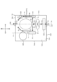
- FIG. 3 is a schematic plan view showing the internal configuration of the machine housing section.
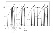
- FIG. 4 is a diagram showing the timing of the operation of the compressor and blower.
- FIG. 5 is a diagram showing the timing of operations of a compressor and a blower constituting a refrigeration system according to a second embodiment of the present invention.
- FIG. 6 is a schematic plan view showing a modified example of the refrigeration device.
- FIG. 1 is a perspective view of a refrigeration device 1 according to an embodiment of the present invention.
- FIG. 2 is a circuit diagram of a cooling device 6.
- FIG. 3 is a schematic plan view showing the internal configuration of a machine storage section 5.
- FIG. 4 is a diagram showing the timing of the operation of a compressor 601 and a blower device 62.
- the freezer 1 is, for example, an ultra-low temperature freezer.
- An ultra-low temperature freezer is one that cools the interior of the freezer to an ultra-low temperature (for example, about -80°C).
- the freezer 1 may also be a medicine refrigerator, a blood refrigerator, or an incubator.
- the Cartesian coordinate system (X, Y, Z) shown in each figure may be used.
- the X direction corresponds to the front-to-rear direction of the refrigeration device 1.
- the + side of the X direction corresponds to the front side of the refrigeration device 1.
- the - side of the X direction corresponds to the rear side of the refrigeration device 1.
- the Y direction corresponds to the left-right direction and width direction of the refrigeration device 1.
- the + side of the Y direction corresponds to the left side when the refrigeration device 1 is viewed from the front.
- the - side of the Y direction corresponds to the right side when the refrigeration device 1 is viewed from the front.
- the Z direction corresponds to the up-down direction of the refrigeration device 1.
- the + side of the Z direction corresponds to the top side of the refrigeration device 1.
- the - side of the Z direction corresponds to the bottom side of the refrigeration device 1.
- the refrigeration device 1 includes a main body 2, a machine storage section 5, and a cooling device 6 (see FIG. 2).
- the main body 2 has a housing 21 and a door 22 that opens and closes the opening.
- the housing 21 has a storage chamber 210 inside that opens upward.
- the storage chamber 210 is a space in which samples are stored, and is cooled to an ultra-low temperature.
- the door 22 opens and closes the opening of the storage chamber 210.
- the machine storage section 5 is provided at the bottom of the main body section 2.
- the machine storage section 5 stores several elements that make up the cooling device 6 that cools the storage chamber 210 of the main body section 2.
- the specific configuration of the machine storage section 5 and the elements that make up the cooling device 6 housed in the machine storage section 5 will be described later.
- the cooling device 6 has a cooling circuit 60, a blower 62, and a control device 63.
- the cooling circuit 60 cools the storage chamber 210 of the housing 21.
- the cooling circuit 60 has a compressor 601, a condenser 602, a dryer 603, a gas-liquid separator 604, an expansion device 605, an evaporator 606, a heat exchanger 607, a second heat exchanger 608, and a second expansion device 609.
- each element 601 to 609 that constitutes the cooling circuit 60 is connected via piping 600.
- the refrigerant then circulates through the cooling circuit 60.
- Compressor 601 compresses the refrigerant so that the pressure value of the refrigerant is 1 MPa or more. This causes the refrigerant to circulate through the cooling circuit 60.
- the high-temperature refrigerant compressed by compressor 601 flows into condenser 602.
- the refrigerant is a non-azeotropic refrigerant mixture that is a mixture of a high-boiling point refrigerant, a medium-boiling point refrigerant with a boiling point lower than that of the high-boiling point refrigerant, and a low-boiling point refrigerant with a boiling point lower than that of the medium-boiling point refrigerant.
- the condenser 602 is, for example, a wire tube type condenser. This allows the refrigerant to be cooled efficiently.
- the refrigerant that passes through the condenser 602 flows into the dryer 603.
- the condenser 602 may also be, for example, a pipe-on-sheet type condenser, a cross-fin type condenser, or a microchannel condenser.
- the dryer 603 removes moisture contained in the refrigerant.
- the function of the dryer 603 is similar to that of dryers in conventional refrigeration systems, so a detailed explanation is omitted.
- the gas-liquid separator 604 is disposed between the dryer 603 and the second heat exchanger 608 described below.
- the gas-liquid separator 604 separates the refrigerant flowing from the dryer 603 to the second heat exchanger 608 into gas-phase refrigerant and liquid-phase refrigerant.
- a portion of the high boiling point refrigerant is liquefied in the refrigerant flowing from the dryer 603 to the second heat exchanger 608.
- the liquid phase refrigerant flowing out of the gas-liquid separator 604 is depressurized by the second expansion device 609.
- the liquid phase refrigerant then flows into the outer tube 608b of the second heat exchanger 608.
- the liquid phase refrigerant merges with the return refrigerant and cools the refrigerant flowing through the inner tube 608a of the second heat exchanger 608.
- the gas phase refrigerant is a high boiling point refrigerant, a medium boiling point refrigerant, and a low boiling point refrigerant in a gaseous state.
- the gas phase refrigerant flowing out of the gas-liquid separator 604 flows into the inner tube 608a of the second heat exchanger 608.
- the heat exchanger 607 is a double-tube type heat exchanger.
- the heat exchanger 607 is disposed between the dryer 603 and the evaporator 606.
- the inner tube 607a of the heat exchanger 607 constitutes the expansion device 605.
- the expansion device 605 is, for example, a capillary tube.
- the refrigerant flows from the compressor 601 to the evaporator 606 through the expansion device 605.
- the refrigerant flows from the evaporator 606 to the compressor 601 through the outer tube 607b of the heat exchanger 607.
- the refrigerant flowing from the evaporator 606 to the compressor 601 is referred to as the return refrigerant.
- the second heat exchanger 608 is a double-pipe type heat exchanger.
- the second heat exchanger 608 is disposed between the dryer 603 and the heat exchanger 607.
- the refrigerant flows from the compressor 601 toward the evaporator 606 through the inner pipe 608a of the second heat exchanger 608.
- the return refrigerant flows through the outer pipe 608b of the second heat exchanger 608.
- the second heat exchanger 608 may be covered with a heat insulating material (e.g., foam).
- the evaporator 606 is arranged around the storage chamber 210 of the housing 21.
- the evaporator 606 vaporizes the refrigerant that flows in from the expansion device 605.
- an expansion tank 610 is connected to the piping element 600a that is connected to the inlet of the compressor 601.
- the expansion tank 610 has the function of adjusting the amount of refrigerant circulating through the cooling circuit 60 by storing a portion of the gas phase refrigerant flowing through the piping element 600a.
- the compressor 601, condenser 602, dryer 603, gas-liquid separator 604, and expansion tank 610 are arranged in the machine storage section 5.
- the blower 62 is a blower such as a fan.
- the cooling device 6 has at least one blower 62 that cools the compressor 601 and the condenser 602.
- the blower 62 is composed of one AC fan motor.
- the blower 62 is disposed in the machine storage section 5.
- the blower 62 is disposed in a position in the machine storage section 5 where it can simultaneously cool the compressor 601 and the condenser. The specific location of the blower 62 will be described later.
- the control device 63 is an example of a control unit, and includes a main control unit 630 and a control relay unit 631.
- the main control unit 630 is, for example, an electronic circuit board.
- the main control unit 630 controls the operation of the compressor 601 based on the detection value of the temperature sensor 7 (see FIG. 2) described below.
- the control relay unit 631 is connected to a circuit that connects the main control unit 630 and the compressor 601.
- the control relay unit 631 switches the compressor 601 between stopped and driven under the control of the main control unit 630.
- the control device 63 having the above configuration controls the operation of the compressor 601 at startup and during normal operation. In other words, the control device 63 switches between stopping and driving the compressor 601 in the cooling control (hereinafter sometimes simply referred to as "cooling control") that cools the storage chamber 210 of the housing 21.
- cooling control hereinafter sometimes simply referred to as "cooling control”
- the state in which the compressor 601 is stopped is sometimes referred to as the stopped state of the compressor 601.
- the state in which the compressor 601 is operating is sometimes referred to as the operating state of the compressor 601.
- the compressor 601 compresses and sends out the refrigerant. In other words, the compressor 601 circulates the refrigerant within the cooling circuit 60.
- Such a control device 63 is connected to a power source (not shown) and the compressor 601.
- the compressor 601 is connected to the power source via the control device 63.
- the control device 63 (specifically, the main control unit 630) also controls the operation of the blower 62.
- the main control unit 630 switches between stopping and driving the blower 62.
- the state in which the blower 62 is stopped is sometimes referred to as the stopped state of the blower 62.
- the state in which the blower 62 is driven is sometimes referred to as the driven state of the blower 62.
- the detailed functions of the control device 63 (specifically, the main control unit 630) will be described later.
- control device that controls the operation of the compressor 601 and the control device that controls the operation of the blower 62 may be different control devices.
- control device that controls the operation of the compressor 601 and the control device that controls the operation of the blower 62 may be connected to each other so that they can communicate with each other.
- Figure 3 is a plan view of the machine storage section 5 as viewed from above.
- the upper side in FIG. 3 corresponds to the rear side of the refrigeration device 1.
- the lower side in FIG. 3 corresponds to the front side of the refrigeration device 1.
- the right side in FIG. 3 corresponds to the right side of the refrigeration device 1.
- the left side in FIG. 3 corresponds to the left side of the refrigeration device 1.
- the machine storage section 5 has a box-shaped storage space 50.
- the machine storage section 5 has a bottom wall section 51, a front wall section 52, a rear wall section 53, a left wall section 54, a right wall section 55, and an upper wall section (not shown).
- the space surrounded by the bottom wall portion 51, the front wall portion 52, the rear wall portion 53, the left wall portion 54, the right wall portion 55, and the top wall portion (not shown) is the storage space 50.
- the bottom wall portion 51 is a rectangular plate that is parallel in the front-to-back and left-to-right directions, and forms the bottom surface of the machine storage section 5.
- the front wall 52 is a rectangular plate parallel in the vertical and horizontal directions, and constitutes the front side of the machine storage section 5.
- the front wall 52 has a front ventilation opening 520 that penetrates the front wall 52 in the front-rear direction.
- the rear wall portion 53 is a rectangular plate parallel in the vertical and horizontal directions, and constitutes the rear side of the machine storage section 5.
- the rear wall portion 53 faces the front wall portion 52 in the front-to-rear direction.
- the rear wall portion 53 has a rear ventilation opening 530 that penetrates the rear wall portion 53 in the front-to-rear direction.
- the left wall 54 is a rectangular plate that is parallel in the vertical and front-to-rear directions and forms the left side of the machine storage section 5.
- the right wall portion 55 is a rectangular plate that is parallel in the vertical and front-to-rear directions, and forms the right side of the machine storage section 5.
- the right wall portion 55 faces the left wall portion 54 in the left-right direction.
- the upper wall portion (not shown) is a rectangular plate parallel in the front-to-back and left-to-right directions, and forms the upper surface of the machine storage section 5.
- the upper wall portion (not shown) faces the bottom wall portion 51 in the up-down direction.
- the upper wall portion (not shown) may be considered to be the bottom wall portion of the main body portion 2.
- a compressor 601, a condenser 602, a dryer 603, a gas-liquid separator 604, an expansion tank 610, a blower 62, and a control relay section 631 are arranged.
- the compressor 601, condenser 602, dryer 603, gas-liquid separator 604, expansion tank 610, blower 62, and control relay unit 631 are all arranged in the right-side storage space 500a, which is the space in one half of the storage space 50 in the left-right direction (specifically, the space in the right half).
- the compressor 601, the condenser 602, the dryer 603, the gas-liquid separator 604, the expansion tank 610, the blower 62, and the control relay unit 631 are all disposed in the space to the right of the two-dot chain line ⁇ 1 shown in Fig. 3 in the storage space 50.
- the two-dot chain line ⁇ 1 is a straight line parallel to the front-rear direction and indicates the center position in the left-right direction of the storage space 50.
- the space to the right of the two-dot chain line ⁇ 1 shown in Fig. 3 is the right storage space 500a.
- the compressor 601 is disposed in the rear half of the right-side storage space 500a.
- the condenser 602 is disposed in the front half of the right-side storage space 500a. More specifically, the condenser 602 is disposed in the right-side storage space 500a, near the front wall portion 52.
- the compressor 601 and the condenser 602 are provided on a straight line (a two-dot chain line ⁇ 2 in FIG. 3) that is parallel to the front-rear direction.
- the two-dot chain line ⁇ 2 in FIG. 3 may be regarded as a straight line that passes through the centers of the compressor 601 and the condenser 602 in the left-right direction.
- the right half of the right storage space 500a may be regarded as the rightmost space when the storage space 50 is divided into four in the left-right direction.
- the centers of the compressor 601 and the condenser 602 in the left-right direction are located in the right half of the right-side storage space 500a.
- the right half of the right-side storage space 500a is the space to the right of the two-dot chain line ⁇ 3 in FIG. 3.
- the compressor 601 and the condenser 602 are positioned toward the right side in the storage space 50. The effects and advantages of this configuration will be described later.
- the blower 62 is disposed between the compressor 601 and the condenser 602 in the front-rear direction. Specifically, the blower 62 is disposed in front of the compressor 601. The blower 62 is also disposed behind the condenser 602.
- the blower 62 is disposed on a two-dot chain line ⁇ 2 shown in Fig. 3. That is, the compressor 601, the condenser 602, and the blower 62 are provided on a straight line (the two-dot chain line ⁇ 2 shown in Fig. 3) that is parallel to the front-rear direction.
- the blower 62 draws in air (cooling air) from the front side and blows it out to the rear side as shown by arrows A2 and A3 in Fig. 3.
- the air drawn in by the blower 62 is air that has entered the storage space 50 of the machine storage section 5 from the outside through the front ventilation opening 520 of the front wall portion 52.
- the air sucked in by the blower 62 flows around the condenser 602, thereby cooling the condenser 602. In this way, the blower 62 cools the condenser 602.
- blower 62 blows air towards the compressor 601.
- the air blown by the blower 62 flows around the compressor 601, thereby cooling the compressor 601. In this way, the blower 62 cools the compressor 601.
- the compressor 601 and the condenser 602 are cooled by a single blower device 62.
- This configuration contributes to reducing the number of parts in the cooling device 6 and to making the cooling device 6 more compact.
- the air flow in the storage space 50 will be described later.
- the control device 63 is also arranged on one side of the compressor 601 (specifically, on the left side) in the left-right direction of the compressor 601.
- control device 63 is disposed to the left of the compressor 601 and between the compressor 601 and the condenser 602 in the front-rear direction. In other words, the control device 63 is disposed at a position facing, from the left side, the front passage P1 that is present between the compressor 601 and the condenser 602. The front passage P1 extends in the left-right direction.
- the control device 63 blocks the air flowing in the front passage P1 in the direction indicated by the arrow A4 in Fig. 3. The control device 63 then guides the air rearward while being cooled by the air.
- the expansion tank 610 corresponds to an example of a first device, and is disposed behind the control device 63.
- the expansion tank 610 is disposed on a straight line (a two-dot chain line ⁇ 4 shown in FIG. 3 ) that passes through the center of the control device 63 and is parallel to the front-rear direction.
- the dryer 603 and the gas-liquid separator 604 are arranged in the right-side storage space 500a to the right of the compressor 601 and to the left of the right wall portion 55 of the machine storage section 5.
- the compressor 601, condenser 602, dryer 603, gas-liquid separator 604, expansion tank 610, blower 62, and control relay unit 631 are connected to each other in the relationship shown in FIG. 2.
- the front, rear, left, and right sides of the air flow in the storage space 50 are determined based on the relative positions of the compressor 601 and the blower 62.
- the direction of the air flow in the storage space 50 may differ from the direction indicated by the Cartesian coordinate system (X, Y, Z) shown in Figures 1 and 3.
- the direction in which the blower device 62 is arranged relative to the compressor 601 is the front side.
- the opposite direction to the direction in which the blower device 62 is arranged relative to the compressor 601 is the rear side.
- the front-to-rear direction of the air flow in the storage space 50 coincides with the front-to-rear direction of the refrigeration device 1 (i.e., the X direction in the Cartesian coordinate system shown in Figures 1 and 3).
- the left-right direction when the compressor 601 is viewed from the blower 62 coincides with the left-right direction of the air flow in the storage space 50.
- the left-right direction of the air flow in the storage space 50 coincides with the left-right direction of the refrigeration device 1 (i.e., the Y direction in the Cartesian coordinate system shown in Figures 1 and 3).
- the left side of the compressor 601 when viewed from the blower 62 is the left side in terms of the air flow in the storage space 50.
- the right side of the compressor 601 when viewed from the blower 62 is the right side in terms of the air flow in the storage space 50.
- the direction of air flow in the storage space 50 also applies to the direction of arrangement of the compressor 601, condenser 602, dryer 603, gas-liquid separator 604, expansion tank 610, blower 62, and control relay unit 631 in the storage space 50.
- Air that has entered the storage space 50 from outside passes through the condenser 602 and is sucked into the blower device 62 from the front side, as shown by the arrow A2 in Fig. 3. At this time, the condenser 602 is cooled by the air passing through the condenser 602.
- the air sucked into the blower 62 is sent out to the rear side of the blower 62 as shown by the arrow A3 in Fig. 3.
- the air sent out from the blower 62 is blown onto the compressor 601 from the front side as shown by the arrow A3 in Fig. 3.
- the compressor 601 is cooled by the air blown by the blower 62.
- the air blown into the compressor 601 is diverted by the housing 601a of the compressor 601.
- Compressor 601 has housing 601a. As shown in FIG. 3, housing 601a has an elliptical shape in a plan view. In other words, compressor 601 has an elliptical shape in a plan view. Note that plan view means viewing compressor 601 from above.
- Compressor 601 (specifically, housing 601a) is disposed on a straight line (specifically, dashed two-dot line ⁇ 2 in FIG. 3) that includes the major axis of the ellipse that is the shape of housing 601a in a plan view. Therefore, blower 62 and condenser 602 are also disposed on a straight line (specifically, dashed two-dot line ⁇ 2 in FIG. 3) that includes the major axis of the ellipse that is the shape of housing 601a in a plan view.
- the air blown onto the housing 601a hits the front surface of the housing 601a and is diverted at least in the left and right directions so as to follow the front surface of the housing 601a. Specifically, the air blown onto the housing 601a hits the front surface of the housing 601a and is diverted radially so as to follow the front surface of the housing 601a.
- the amount of air diverted in each direction by the front surface of the housing 601a is determined by the shape of the front surface of the housing 601a. In this embodiment, the amount of air diverted by the front surface of the housing 601a is greatest in the left-right direction. Below, the air flow diverted in the left-right direction by the front surface of the housing 601a will be described. A description of the air flow diverted in directions other than the left-right direction by the front surface of the housing 601a will be omitted.
- the air diverted to the left by the front surface of the housing 601a flows leftward through a front passage P1 existing between the compressor 601 and the condenser 602, as indicated by an arrow A4 in Fig. 3. Then, the air flowing leftward through the front passage P1 hits the control device 63.
- control relay unit 631 is cooled by the air that flows through the front passage P1 and hits the control relay unit 631.
- the control relay unit 631 guides the air that flows through the front passage P1 and hits the control relay unit 631 rearward as shown by the arrow A5 in Fig. 3. It is not necessary for the control relay unit 631 to guide rearward all of the air that flows through the front passage P1 and hits the control relay unit 631.
- the air guided rearward by the control relay 631 flows rearward through a left passage P2 formed on the left side of the compressor 601.
- the left passage P2 corresponds to an example of a first passage.
- the left passage P2 is a passage that is formed by the compressor 601, the control relay 631, and the expansion tank 610 and extends in the front-rear direction.
- the compressor 601 functions as a wall portion on one side (specifically, the right side) of the left passage P2 .
- the control relay unit 631 and the expansion tank 610 function as a wall portion on the other side (specifically, the left side) of the left passage P2 .
- the expansion tank 610 together with the control relay unit 631, guides the air diverted by the compressor 601 rearward.
- another device i.e., a first device
- the gas-liquid separator 604 may have a cylindrical separation section (not shown) that separates the refrigerant, and a plate-shaped base section (not shown) that supports the separation section on the bottom wall section 51 of the machine housing section 5.
- the gas-liquid separator 604 may be disposed at the position of the expansion tank 610 in Fig. 3 with the base section aligned along the left passage P2 in Fig. 3.
- the air flowing through the left passage P2 flows along one side surface (specifically, the left side surface) of the compressor 601. At this time, the compressor 601 is cooled by the air flowing through the left passage P2 .
- the air flowing through the left passage P2 flows rearward of the compressor 601 as indicated by an arrow A6 in Fig. 3. Then, the air flowing rearward of the compressor 601 passes through the rear ventilation opening 530 of the rear wall portion 53 as indicated by an arrow A10 in Fig. 3, and is discharged to the outside of the storage space 50.
- the air diverted to the right by the front surface of the housing 601a flows rightward through a front passage P1 existing between the compressor 601 and the condenser 602, as indicated by an arrow A7 in Fig. 3. Then, the air flowing rightward through the front passage P1 hits the right wall portion 55 of the machine housing portion 5.
- the right wall portion 55 guides the air that flows through the front passage P1 and hits the right wall portion 55 rearward as shown by an arrow A8 in Fig. 3. It is not necessary for the right wall portion 55 to guide rearward all of the air that flows through the front passage P1 and hits the right wall portion 55.
- the right wall portion 55 corresponds to an example of a side wall portion.
- the air guided rearward by the right wall portion 55 flows rearward through a right passage P3 formed on the right side of the compressor 601.
- the right passage P3 corresponds to an example of a second passage.
- the right passage P3 is a passage that is formed by the compressor 601 and the right wall portion 55 and extends in the front-rear direction.
- the compressor 601 functions as a wall portion on one side (specifically, the left side) of the right passage P3 .
- the right wall portion 55 functions as a wall portion on the other side (specifically, the right side) of the right passage P3 .
- the compressor 601, the condenser 602, and the blower 62 are disposed in a position biased toward the right side in the accommodation space 50. Therefore, the right wall portion 55 can be used as a right wall portion of the right passage P3 .
- the air flowing through the right passage P3 flows along the other side surface (specifically, the right side surface) of the compressor 601. At this time, the compressor 601 is cooled by the air flowing through the right passage P3 . In addition, the air flowing through the right passage P3 cools the dryer 603 and the gas-liquid separator 604. Note that if the dryer 603 and the gas-liquid separator 604 are configured to be low in height, they do not interfere with the flow of air flowing through the right passage P3 .
- the operation of the compressor 601 and the blower 62 is controlled by the control device 63.
- the control device 63 switches between stopping and driving the compressor 601 in the cooling control for cooling the storage chamber 210 of the housing 21.
- the control device 63 (specifically, the main control unit 630) also switches between stopping and driving the blower 62 in the cooling control for cooling the storage chamber 210.
- the control device 63 switches between stopping and driving the compressor 601 based on the temperature of the storage chamber 210 of the housing 21.
- the refrigeration device 1 has a temperature sensor 7 (see FIG. 2) that detects the temperature of the storage chamber 210 of the housing 21.
- the temperature sensor 7 is provided at a predetermined position in the storage chamber 210.
- the temperature sensor 7 sends the detection value to the control device 63 (specifically, the main control unit 630).
- the main control unit 630 controls the control relay unit 631 to drive the compressor 601.
- the first predetermined condition is that the temperature of the storage chamber 210 is higher than the target temperature (e.g., -80°C) by a predetermined value (hereinafter referred to as the "first predetermined value").
- the main control unit 630 controls the control relay unit 631 to stop the compressor 601.
- the second predetermined condition is that the temperature of the storage chamber 210 is equal to or nearly equal to the target temperature (e.g., -80°C).
- the operating time of the compressor 601 varies depending on the temperature of the storage room 210. Furthermore, the stop time of the compressor 601 is equal to or longer than the minimum stop time.
- the minimum stop time is an example of a second predetermined time, and is a time that is set in advance.
- the main control unit 630 stores the minimum stop time.
- the main control unit 630 will not drive the compressor 601. In this case, the main control unit 630 will drive the compressor 601 when the time that the compressor 601 is stopped becomes equal to or longer than the minimum stop time.
- the main control unit 630 drives the air blowing device 62 a set start time Tset (see FIG. 4) after stopping the compressor 601.
- the set start time Tset corresponds to an example of a first predetermined time, and is a time that is set in advance.
- the main control unit 630 stores the set start time.
- the set start time Tset (first predetermined time) is shorter than the above-mentioned minimum stop time (second predetermined time).
- the main control unit 630 drives the blower 62 after the set start time has elapsed since the compressor 601 was stopped, thereby making it possible to ventilate the inside of the machine storage unit 5 before the compressor 601 is next driven. Therefore, even if refrigerant leaks inside the machine storage unit 5, the concentration of the refrigerant inside the machine storage unit 5 will decrease before the compressor 601 is driven.
- the main control unit 630 drive the blower 62 a set start time after the compressor 601 is stopped, the rotation speed of the blower 62 can be maximized the next time the compressor 601 is driven. As a result, when the compressor 601 is driven, the blower 62 can efficiently cool the compressor 601.
- the main control unit 630 stops the air blower 62 at the same time as stopping the compressor 601. This configuration contributes to energy conservation. Note that the timing at which the compressor 601 stops and the timing at which the air blower 62 stops may be different.
- FIG. 4 is a diagram showing the operation timing of the compressor 601 and the blower 62.
- a pulse waveform L1 indicated by a thin solid line indicates the timing of the operation of the compressor 601.
- the compressor 601 is driven (that is, goes into a driving state).
- the compressor 601 stops (i.e., goes into a stopped state). In the cooling control, the compressor 601 repeats driving (ON) and stopping (OFF) under the control of the main control unit 630.
- the horizontal axis in FIG. 4 represents time.
- a pulse waveform L2 indicated by a thick solid line indicates the timing of operation of the blower 62.
- the blower 62 is driven (i.e., the blower 62 is in a driven state).
- the blower 62 stops (i.e., goes into a stopped state). In the cooling control, the blower 62 repeatedly turns on (ON) and off (OFF) under the control of the main control unit 630.
- the height of the pulse waveform L1 and the height of the pulse waveform L2 are different in FIG. 4.
- the concentration C of the refrigerant in the machine storage section 5 is shown by a dotted line when it is assumed that the refrigerant has leaked inside the machine storage section 5.
- the horizontal axis is time.
- the vertical axis is concentration.
- the scale indicating the concentration on the vertical axis is omitted in Fig. 4.
- the refrigerant concentration C in Fig. 4 is shown to repeatedly change between a maximum concentration C high and a minimum concentration C low .
- the temperature T of the storage room 210 is shown by a dashed line.
- the horizontal axis is time.
- the vertical axis is temperature. Note that, in FIG. 4, the scale indicating temperature on the vertical axis is omitted.
- the main control unit 630 controls the control relay unit 631 to drive the compressor 601. At this time, the blower 62 is stopped.
- the main control unit 630 controls the control relay unit 631 to stop the compressor 601 at time t2 in Fig. 4.
- the difference between time t2 and time t1 in Fig. 4 is the driving time of the compressor 601.
- the driving time of the compressor 601 changes depending on the rate of change in temperature of the storage chamber 210.
- the main control unit 630 determines the time (time T 1 in FIG. 4) to drive the blower 62 based on the time (time t 2 in FIG. 4) when the compressor 601 is stopped.
- the main control unit 630 determines the time obtained by adding the pre-stored set start time Tset to the time t2 as the time to drive the blower device 62.
- the difference between the time T1 and the time t2 in FIG. 4 is the set start time Tset .
- the main control unit 630 controls the control relay unit 631 to stop the compressor 601, and then after the set start time Tset , controls the control relay unit 631 to drive the blower 62. In other words, after stopping the compressor 601, the main control unit 630 drives the blower 62 at time T1 in FIG.
- the concentration C of the refrigerant inside the machinery housing section 5 increases as time passes from the time t1 when the compressor 601 is driven.
- the concentration C of the refrigerant in the machine housing section 5 becomes the maximum concentration C high immediately before the time T1 when the blower device 62 is driven.
- the main control section 630 drives the blower device 62 before time t3 at which the compressor 601 is driven.
- the time when the compressor 601 operates is not predetermined. In other words, the time when the compressor 601 operates varies depending on the temperature T of the storage room 210. For this reason, the time when the blower device 62 operates cannot be determined based on the time when the compressor 601 operates. Therefore, in the case of this embodiment, the time when the blower device 62 operates is determined based on the time when the compressor 601 stops (time t2 in FIG. 4).
- the main control unit 630 After driving the blower 62 at time T1 , the main control unit 630 drives the compressor 601 at time t3 in Fig. 4. The main control unit 630 determines the timing to drive the compressor 601 based on the temperature of the storage room 210.
- the main control unit 630 drives the compressor 601 when the temperature of the storage chamber 210 of the housing 21 satisfies a predetermined condition (first predetermined condition). At this time, the blower 62 is driven (i.e., in a driven state). Since the blower 62 is driven before time t3 in Fig. 4, as shown by the refrigerant concentration C in Fig. 4, the refrigerant concentration C is the minimum concentration C low at time t3 in Fig. 4.
- the main control unit 630 stops the compressor 601.
- the main control unit 630 determines the timing to stop the compressor 601 based on the temperature of the storage chamber 210 of the housing 21.
- the main control unit 630 stops the compressor 601 at time t4 in Fig. 4. Moreover, the main control unit 630 stops the air blower 62 at the same time as stopping the compressor 601.
- the timing at which the main control unit 630 stops the blower 62 is the same as the timing at which the compressor 601 is stopped. Therefore, when the compressor 601 is in a driven state, the compressor 601 is constantly cooled by the blower 62.
- the compressor 601 is efficiently cooled by the blower 62.
- the main control unit 630 stops the compressor 601 and then determines the time (time T3 in FIG. 4) to drive the blower 62 based on the time (time t4 in FIG. 4) at which the compressor 601 is stopped.
- the subsequent control of the compressor 601 and the blower 62 by the main control unit 630 is as described above.
- the above-mentioned layout of the machinery housing section 5 is adopted. Therefore, in the machinery housing section 5, air taken in from the outside by the blower 62 can be efficiently guided to the outside as shown by arrows A1 to A10 in Fig. 3. In other words, if a refrigerant leaks inside the machinery housing section 5, the machinery housing section 5 can be efficiently ventilated.
- the blower 62 and the condenser 602 are arranged on the same straight line (on the two-dot chain line ⁇ 2 shown in FIG. 3 ). Therefore, if it is assumed that the refrigerant leaks from the condenser 602, the leaked refrigerant can be efficiently guided to the outside as shown by the arrows A 1 to A 10 in FIG.
- FIG. 2 A refrigeration device according to a second embodiment of the present invention will be described with reference to Figures 2, 3, and 5.
- Figure 5 is a diagram showing the timing of the operation of the compressor 601 and the blower device 62.
- the control operation of the main control unit 630 in the control device 63 differs from the control operation of the main control unit 630 in the first embodiment.
- the configuration of the main control unit 630 other than its functions is the same as that of the refrigeration device 1 according to the first embodiment described above. Therefore, for the description of the configuration of the main control unit 630 other than its functions, refer to Figures 2 and 3.
- the main control unit 630 performs temporary drive control to temporarily drive the blower device 62 before the set start time Tset has elapsed after the compressor 601 is stopped.
- the set start time Tset is a time that is set in advance.
- the control performed by the main control unit 630 from driving the blower 62 at time T a in FIG. 5 until stopping the blower 62 at time T b in FIG. 5 is the temporary drive control.
- FIG. 5 is a diagram showing the operation timing of the compressor 601 and the blower 62.
- a pulse waveform L1a indicated by a thin solid line indicates the timing of the operation of the compressor 601.
- the compressor 601 is driven (that is, goes into a driving state).
- the compressor 601 stops (i.e., goes into a stopped state). In the cooling control, the compressor 601 repeats driving (ON) and stopping (OFF) under the control of the main control unit 630.
- the horizontal axis in FIG. 5 represents time.
- pulse waveforms L2a and L2b indicated by thick solid lines indicate the operation timing of the blower 62.
- the blower 62 is driven (i.e., the blower 62 is in a driven state).
- the blower 62 stops (i.e., goes into a stopped state). In the cooling control, the blower 62 repeats driving (ON) and stopping (OFF) under the control of the main control unit 630.
- the height of the pulse waveform L1a is different from the heights of the pulse waveforms L2a and L2b .
- the concentration C of the refrigerant in the machine housing section 5 is shown by a dotted line when it is assumed that the refrigerant has leaked inside the machine housing section 5. Note that for the refrigerant concentration C in Figure 4, the horizontal axis is time.
- the vertical axis represents the concentration. Note that the scale indicating the concentration on the vertical axis is omitted in Fig. 5.
- the refrigerant concentration C in Fig. 5 is shown to repeatedly change between a maximum concentration C high and a minimum concentration C low .
- the temperature T of the storage chamber 210 (see FIG. 2) of the housing 21 is shown by a dashed line.
- the horizontal axis represents time.
- the vertical axis represents temperature. Note that the scale indicating temperature on the vertical axis has been omitted in FIG. 5.
- the main control unit 630 first drives the compressor 601 at time t1 in Fig. 5. At this time, the blower 62 is stopped.
- the main control unit 630 stops the compressor 601 at time t2 in Fig. 5.
- the difference between time t2 and time t1 in Fig. 5 is the driving time of the compressor 601.
- the driving time of the compressor 601 changes depending on the rate of change in temperature of the storage chamber 210.
- the main control unit 630 determines the time (time T 1 in FIG. 5) to drive the blower 62 based on the time (time t 2 in FIG. 5) when the compressor 601 is stopped.
- the main control unit 630 determines the time obtained by adding the pre-stored set start time Tset to the time t2 as the time to drive the blower device 62.
- the difference between the time T1 and the time t2 in FIG. 4 is the set start time Tset .
- the set start time Tset is longer than the set start time Tset in the above-described embodiment 1. That is, the time from when the compressor 601 stops to when the blower device 62 is driven is long.
- the set start time Tset may also be set in advance.
- the reason why the set start time Tset in this embodiment is longer than the set start time Tset in the first embodiment is, for example, because the stop time of the compressor 601 is longer.
- the stop time of the compressor 601 is the time from time t2 to time t3 in Fig. 5.
- the main control unit 630 determines the timing to stop the compressor 601 (for example, time t3 in Fig. 5) based on the temperature of the storage room 210. Therefore, the stop time of the compressor 601 is not a predetermined value.
- the stop time of the compressor 601 can be estimated based on information on the usage status of the refrigeration device 1.
- the main control unit 630 may determine the set start time Tset in accordance with the estimated stop time of the compressor 601 based on the information on the usage status of the refrigeration device 1. That is, in this embodiment, the set start time Tset may be a variable value determined by the main control unit 630.
- the main control unit 630 can estimate the stop time of the compressor 601 based on the temperature of the storage room 210 and the air temperature outside the refrigeration device 1 (in other words, the outside air temperature).
- the air temperature outside the refrigeration device 1 is relatively low, the temperature of the storage room 210 is relatively unlikely to rise. Therefore, the stop time of the compressor 601 is relatively long.
- the main control unit 630 estimates the stop time of the compressor 601.
- the main control unit 630 may set the set start time Tset based on the estimated stop time of the compressor 601. In this embodiment, the main control unit 630 performs the temporary drive control when the stop time of the compressor is longer than a third predetermined time.
- the third predetermined time may be a time set in advance.
- the main control unit 630 drives the blower 62 at time T a between the time when the compressor 601 is stopped (time t 2 in Fig. 5) and the time when the blower 62 is scheduled to be driven (time T 1 in Fig. 5). In other words, the main control unit 630 starts temporary drive control of the blower 62.
- the main control unit 630 stops the blower device 62 after a predetermined time has elapsed since the blower device 62 was driven (i.e., time T a in FIG. 5 ). That is, the main control unit 630 ends the temporary drive control of the blower device 62. While the temporary drive control is being performed, the compressor 601 is stopped.
- the drive time of the blower device 62 in the temporary drive control (i.e., the difference between time Tb and time T a ) may be a predetermined time.
- the main control unit 630 may store the drive time of the blower device 62 in the temporary drive control. Such temporary drive control of the blower device 62 can efficiently ventilate the inside of the machine housing section 5 when the compressor 601 is stopped for a long time.
- the main control unit 630 drives the blower 62.
- Such control by the main control unit 630 is sometimes referred to as normal drive control of the blower 62.
- the main control unit 630 performs temporary drive control of the blower device 62 in addition to normal drive control of the blower device 62.
- the concentration C of the refrigerant inside the machinery housing section 5 increases as time passes from the time t1 when the compressor 601 is driven.
- the main control unit 630 performs the above-mentioned temporary drive control, so that after the temporary drive control is performed (i.e., after time Ta ), the concentration C of the refrigerant in the machinery housing section 5 decreases.
- the blower device 62 is driven at time T1 , so that the inside of the machinery housing section 5 can be reliably ventilated before time t3 when the compressor 601 is driven.
- the concentration C of the refrigerant in the machinery housing section 5 can be reliably reduced before time t3 when the compressor 601 is driven.
- the main control unit 630 After driving the blower 62 at time T1 , the main control unit 630 drives the compressor 601 at time t3 in Fig. 5. The main control unit 630 determines the timing to drive the compressor 601 based on the temperature of the storage room 210.
- the main control unit 630 drives the compressor 601. At this time, the blower 62 is driven (i.e., in a driven state). Since the blower 62 is driven before time t3 in Fig. 5, as shown by the refrigerant concentration C in Fig. 5, the refrigerant concentration C is the minimum concentration C low at time t3 in Fig. 5.
- the main control unit 630 stops the compressor 601.
- the main control unit 630 determines the timing to stop the compressor 601 based on the temperature of the storage room 210.
- the main control unit 630 stops the compressor at time t4 in Fig. 5. Furthermore, the main control unit 630 stops the air blower 62 at the same time as stopping the compressor 601.
- the timing at which the main control unit 630 stops the blower 62 is the same as the timing at which the compressor 601 is stopped. Therefore, when the compressor 601 is in a driven state, the compressor 601 is constantly cooled by the blower 62.
- the compressor 601 is efficiently cooled by the blower 62. Thereafter, the main control unit 630 stops the compressor 601 and then determines the time (time T3 in FIG. 5) to drive the blower 62 based on the time (time t4 in FIG. 5) at which the compressor 601 is stopped. Thereafter, the main control unit 630 controls the compressor 601 and the blower 62 as described above.
- the other configurations and functions and effects are the same as those of the first embodiment described above.
- the configuration of the machine storage section is not limited to the configuration of the machine storage section 5 described above.
- the machine storage section may be a machine storage section 5A shown in Fig. 6.
- the machine storage section 5A is narrower than the machine storage section 5 in the above embodiment.
- the dimension of the machine storage section 5A in the left-right direction is half the dimension of the machine storage section 5 in the left-right direction.
- the machine storage section 5A has a box-shaped storage space 50A.
- the machine storage section 5A also has a bottom wall 51A, a front wall 52A, a rear wall 53A, a left wall 54A, a right wall 55A, and a top wall (not shown).
- the configurations of the storage space 50A, the bottom wall 51A, the front wall 52A, the rear wall 53A, the left wall 54A, the right wall 55A, and the top wall (not shown) are substantially the same as the configurations of the storage space 50, the bottom wall 51, the front wall 52, the rear wall 53, the left wall 54, the right wall 55, and the top wall in the above-mentioned embodiment, except for the difference in size. Otherwise, the configuration shown in FIG. 6 is the same as the configuration shown in FIG. 3.
- the compressor 601, the condenser 602, and the blower 62 are arranged on a straight line (double-dashed line ⁇ 2 in FIG. 3) parallel to the front-rear direction.
- the compressor, the condenser, and the blower may be arranged on a straight line (not shown) parallel to a direction other than the front-rear direction (for example, the left-right direction).
- a straight line not shown
- a direction other than the front-rear direction for example, the left-right direction
- the blower device 62 in the above embodiment is configured with one AC fan motor
- the configuration of the blower device is not limited to the configuration of the blower device 62.
- the blower device may be configured with multiple (e.g., four) DC fan motors that are smaller than the AC fan motor that configures the blower device 62.
- the four DC fan motors may be arranged in two rows, one above the other and two rows, one left and one right.
- the refrigeration device does not need to have all of the configurations described above.
- the configurations of the refrigeration device may be selected as appropriate within the scope of technical compatibility.
- the present invention can be applied to various types of refrigeration equipment.
- Refrigeration equipment 2 Main unit 21 Housing 210 Storage room 22 Door 5 Machine storage 50, 50A Housing space 500a Right housing space 51, 51A Bottom wall 52, 52A Front wall 520 Front ventilation port 53, 53A Rear wall 530 Rear ventilation port 54, 54A Left wall section 55, 55A Right wall section P 1 Front passage P 2 Left passage P 3 Right passage 6 Cooling device 60 Cooling circuit 600 Piping 600a Piping element 601 Compressor 601a Housing 602 Condenser 603 Dryer 604 Gas-liquid separator 605 Expansion Device 606 Evaporator 607 Heat exchanger 607a inner tube 607b outer tube 608 Second heat exchanger 608a Inner pipe 609 Second expansion device 610 Expansion tank 62 Blower device 63 Control device 630 Main control unit 631 Control relay unit 7 Temperature sensor
Landscapes
- Engineering & Computer Science (AREA)
- Physics & Mathematics (AREA)
- Mechanical Engineering (AREA)
- Thermal Sciences (AREA)
- General Engineering & Computer Science (AREA)
- Chemical & Material Sciences (AREA)
- Combustion & Propulsion (AREA)
- Devices That Are Associated With Refrigeration Equipment (AREA)
Priority Applications (3)
| Application Number | Priority Date | Filing Date | Title |
|---|---|---|---|
| JP2025533973A JPWO2025018180A1 (https=) | 2023-07-14 | 2024-07-05 | |
| CN202480041347.2A CN121358994A (zh) | 2023-07-14 | 2024-07-05 | 冷冻装置 |
| EP24842973.0A EP4726294A1 (en) | 2023-07-14 | 2024-07-05 | Refrigeration device |
Applications Claiming Priority (2)
| Application Number | Priority Date | Filing Date | Title |
|---|---|---|---|
| JP2023-115969 | 2023-07-14 | ||
| JP2023115969 | 2023-07-14 |
Publications (1)
| Publication Number | Publication Date |
|---|---|
| WO2025018180A1 true WO2025018180A1 (ja) | 2025-01-23 |
Family
ID=94281967
Family Applications (1)
| Application Number | Title | Priority Date | Filing Date |
|---|---|---|---|
| PCT/JP2024/024416 Pending WO2025018180A1 (ja) | 2023-07-14 | 2024-07-05 | 冷凍装置 |
Country Status (4)
| Country | Link |
|---|---|
| EP (1) | EP4726294A1 (https=) |
| JP (1) | JPWO2025018180A1 (https=) |
| CN (1) | CN121358994A (https=) |
| WO (1) | WO2025018180A1 (https=) |
Citations (5)
| Publication number | Priority date | Publication date | Assignee | Title |
|---|---|---|---|---|
| JP2004190917A (ja) | 2002-12-10 | 2004-07-08 | Sanyo Electric Co Ltd | 冷凍装置 |
| JP2020085363A (ja) * | 2018-11-27 | 2020-06-04 | ホシザキ株式会社 | 冷却機器 |
| WO2021111624A1 (ja) * | 2019-12-06 | 2021-06-10 | 三菱電機株式会社 | ショーケース |
| JP2023115734A (ja) * | 2022-02-08 | 2023-08-21 | ホシザキ株式会社 | 冷却装置 |
| JP2023115969A (ja) | 2022-02-09 | 2023-08-22 | 株式会社インテック | 図面解析方法、図面解析プログラム及び図面解析システム |
-
2024
- 2024-07-05 JP JP2025533973A patent/JPWO2025018180A1/ja active Pending
- 2024-07-05 WO PCT/JP2024/024416 patent/WO2025018180A1/ja active Pending
- 2024-07-05 CN CN202480041347.2A patent/CN121358994A/zh active Pending
- 2024-07-05 EP EP24842973.0A patent/EP4726294A1/en active Pending
Patent Citations (5)
| Publication number | Priority date | Publication date | Assignee | Title |
|---|---|---|---|---|
| JP2004190917A (ja) | 2002-12-10 | 2004-07-08 | Sanyo Electric Co Ltd | 冷凍装置 |
| JP2020085363A (ja) * | 2018-11-27 | 2020-06-04 | ホシザキ株式会社 | 冷却機器 |
| WO2021111624A1 (ja) * | 2019-12-06 | 2021-06-10 | 三菱電機株式会社 | ショーケース |
| JP2023115734A (ja) * | 2022-02-08 | 2023-08-21 | ホシザキ株式会社 | 冷却装置 |
| JP2023115969A (ja) | 2022-02-09 | 2023-08-22 | 株式会社インテック | 図面解析方法、図面解析プログラム及び図面解析システム |
Also Published As
| Publication number | Publication date |
|---|---|
| CN121358994A (zh) | 2026-01-16 |
| EP4726294A1 (en) | 2026-04-15 |
| JPWO2025018180A1 (https=) | 2025-01-23 |
Similar Documents
| Publication | Publication Date | Title |
|---|---|---|
| WO2015040850A1 (ja) | エジェクタ式冷凍サイクル | |
| WO2016121385A1 (ja) | 空調装置 | |
| US10041716B2 (en) | Refrigerator | |
| JP4415835B2 (ja) | 車両用冷凍サイクル装置 | |
| WO2018047540A1 (ja) | 機器温調装置 | |
| WO2024127924A1 (ja) | 空調ユニット | |
| JP2015128916A (ja) | 冷凍サイクル装置 | |
| WO2025018180A1 (ja) | 冷凍装置 | |
| JP7081460B2 (ja) | 小型空調装置 | |
| WO2016021262A1 (ja) | ヒートポンプ | |
| WO2023218834A1 (ja) | 圧縮機モジュール | |
| KR20150145852A (ko) | 냉장고 및 그 제어방법 | |
| JP7241469B2 (ja) | ショーケース | |
| WO2004113806A1 (ja) | 冷却装置 | |
| WO2022210794A1 (ja) | ヒートポンプ装置 | |
| JP2006082604A (ja) | 車両用冷蔵庫 | |
| JP2007225169A (ja) | 空調装置 | |
| WO2025018181A1 (ja) | 冷凍装置 | |
| EP1980806A2 (en) | An apparatus for refrigeration | |
| CN114562838A (zh) | 制冷剂回路装置 | |
| JP5407621B2 (ja) | 冷却加熱装置 | |
| JP7081461B2 (ja) | 小型空調装置 | |
| JPH11230662A (ja) | 冷蔵庫 | |
| JP4070736B2 (ja) | 冷蔵庫および冷凍サイクル用電動弁 | |
| JP4745176B2 (ja) | 冷媒サイクル装置 |
Legal Events
| Date | Code | Title | Description |
|---|---|---|---|
| 121 | Ep: the epo has been informed by wipo that ep was designated in this application |
Ref document number: 24842973 Country of ref document: EP Kind code of ref document: A1 |
|
| ENP | Entry into the national phase |
Ref document number: 2025533973 Country of ref document: JP Kind code of ref document: A |
|
| WWE | Wipo information: entry into national phase |
Ref document number: 2025533973 Country of ref document: JP |
|
| WWE | Wipo information: entry into national phase |
Ref document number: 2024842973 Country of ref document: EP |
|
| ENP | Entry into the national phase |
Ref document number: 2024842973 Country of ref document: EP Effective date: 20260108 |
|
| ENP | Entry into the national phase |
Ref document number: 2024842973 Country of ref document: EP Effective date: 20260108 |
|
| ENP | Entry into the national phase |
Ref document number: 2024842973 Country of ref document: EP Effective date: 20260108 |
|
| ENP | Entry into the national phase |
Ref document number: 2024842973 Country of ref document: EP Effective date: 20260108 |
|
| NENP | Non-entry into the national phase |
Ref country code: DE |
|
| WWP | Wipo information: published in national office |
Ref document number: 2024842973 Country of ref document: EP |