WO2025018134A1 - 基板処理装置及び基板処理方法 - Google Patents
基板処理装置及び基板処理方法 Download PDFInfo
- Publication number
- WO2025018134A1 WO2025018134A1 PCT/JP2024/023748 JP2024023748W WO2025018134A1 WO 2025018134 A1 WO2025018134 A1 WO 2025018134A1 JP 2024023748 W JP2024023748 W JP 2024023748W WO 2025018134 A1 WO2025018134 A1 WO 2025018134A1
- Authority
- WO
- WIPO (PCT)
- Prior art keywords
- processing
- temperature
- pressure
- fluid
- processing vessel
- Prior art date
- Legal status (The legal status is an assumption and is not a legal conclusion. Google has not performed a legal analysis and makes no representation as to the accuracy of the status listed.)
- Pending
Links
Images






Classifications
-
- H—ELECTRICITY
- H10—SEMICONDUCTOR DEVICES; ELECTRIC SOLID-STATE DEVICES NOT OTHERWISE PROVIDED FOR
- H10P—GENERIC PROCESSES OR APPARATUS FOR THE MANUFACTURE OR TREATMENT OF DEVICES COVERED BY CLASS H10
- H10P52/00—Grinding, lapping or polishing of wafers, substrates or parts of devices
Definitions
- This disclosure relates to a substrate processing apparatus and a substrate processing method.
- Patent Document 1 discloses a configuration for switching the temperature of the supercritical fluid supplied to the substrate.
- This disclosure provides technology that can suppress particle generation.
- a substrate processing apparatus includes a processing vessel for accommodating a substrate, a supply source for supplying a processing fluid into the processing vessel, a fluid supply path connecting the supply source and the processing vessel, a temperature adjustment unit provided in the fluid supply path for adjusting the temperature of the processing fluid, a pressure adjustment unit for adjusting the pressure in the processing vessel, an on-off valve provided in the fluid supply path downstream of the temperature adjustment unit, a first temperature sensor provided in the fluid supply path downstream of the on-off valve, and a control circuit for controlling the operation of the temperature adjustment unit, and the control circuit controls at least one of the temperature adjustment unit and the pressure adjustment unit so that the temperature detected by the first temperature sensor is maintained above a critical temperature.
- particle generation can be suppressed.
- FIG. 1 is a diagram showing a substrate processing apparatus according to a first embodiment.
- FIG. 2 is a flowchart showing the substrate processing method according to the first embodiment.
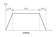
- FIG. 3 is a diagram showing a pressure change in the processing vessel in the substrate processing method of FIG.
- FIG. 4 is a diagram showing a substrate processing apparatus according to the second embodiment.
- FIG. 5 is a flowchart showing a substrate processing method according to the second embodiment.
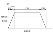
- FIG. 6 is a diagram showing a pressure change in the processing vessel in the substrate processing method of FIG.
- FIG. 7 is a diagram (1) showing a temperature change of the processing fluid in the fluid supply path.
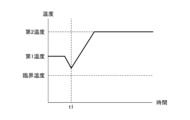
- FIG. 8 is a diagram (2) showing the temperature change of the processing fluid in the fluid supply path.
- FIG. 9 is a diagram for explaining pattern collapse.
- FIG. 1 is a diagram showing the substrate processing apparatus 10 according to the first embodiment.
- the substrate processing apparatus 10 has a processing section 11, a supply section 12, a discharge section 13, and a control section 14.
- the processing section 11 has a processing vessel 111 and a holding section 112.
- the processing vessel 111 is a vessel in which a processing space capable of accommodating a substrate W having a diameter of, for example, 300 mm is formed inside.
- the substrate W may be, for example, a semiconductor wafer.
- the holding section 112 is provided inside the processing vessel 111.
- the holding section 112 holds the substrate W horizontally.
- the holding section 112 is, for example, configured integrally with the processing vessel 111.
- the holding section 112 may be a holding plate configured separately from the processing vessel 111.
- the processing section 11 has a temperature sensor T14 and a pressure sensor P14.
- the temperature sensor T14 detects the temperature inside the processing vessel 111.
- the pressure sensor P14 detects the pressure inside the processing vessel 111.
- the supply unit 12 has a fluid supply source S11 and a fluid supply path L11.
- the fluid supply S11 is a supply source of a process fluid, which may be, for example, carbon dioxide (CO 2 ) in a liquid state.
- a process fluid which may be, for example, carbon dioxide (CO 2 ) in a liquid state.
- the fluid supply path L11 is connected to a fluid supply source S11 at its upstream end and to a processing vessel 111 at its downstream end.
- a heating mechanism HE11, a temperature sensor T11, an on-off valve V11, an orifice OR11, a temperature sensor T13, and a pressure sensor P13 are provided in this order from upstream.
- a line heater LH11 is provided downstream of the heating mechanism HE11 in the fluid supply path L11.
- On-off valves, temperature sensors, pressure sensors, and filters may also be provided at various positions in the fluid supply path L11. The filter filters the processing fluid flowing through the fluid supply path L11 and removes foreign matter contained in the processing fluid. This makes it possible to suppress the generation of particles on the surface of the substrate W during substrate processing using the processing fluid.
- the heating mechanism HE11 heats the process fluid supplied from the fluid supply source S11 and supplies the heated fluid downstream.
- the temperature sensor T11 is provided in the fluid supply path L11 downstream of the heating mechanism HE11 and upstream of the on-off valve V11.
- the temperature sensor T11 detects the temperature of the processing fluid flowing through the fluid supply path L11.
- the on-off valve V11 is a valve that switches the flow of the treatment fluid on and off. When the on-off valve V11 is open, it allows the treatment fluid to flow to the downstream orifice OR11, and when it is closed, it does not allow the treatment fluid to flow to the downstream orifice OR11.
- the orifice OR11 has the function of reducing the flow rate of the processing fluid and adjusting the pressure.
- the orifice OR11 passes the pressure-adjusted processing fluid to the downstream processing vessel 111.
- the temperature sensor T13 is provided in the fluid supply path L11 downstream of the orifice OR11 and upstream of the processing vessel 111.
- the temperature sensor T13 detects the temperature of the processing fluid flowing through the fluid supply path L11 just before the processing vessel 111.
- the pressure sensor P13 is provided in the fluid supply path L11 downstream of the orifice OR11 and upstream of the processing vessel 111.
- the pressure sensor P13 detects the pressure of the fluid supply path L11 immediately before the processing vessel 111.
- the line heater LH11 heats the fluid supply path L11 downstream of the heating mechanism HE11.
- the line heater LH11 prevents the temperature of the treatment fluid heated to the first temperature by the heating mechanism HE11 from decreasing as it flows through the fluid supply path L11.
- the discharge section 13 has a discharge flow path L13.
- the discharge flow path L13 is connected to the processing vessel 111.
- An on-off valve V13 and a back pressure valve BV13 are provided in the discharge flow path L13, in that order from upstream.
- a line heater LH13 is provided in the discharge flow path L13.
- An on-off valve, a temperature sensor, and a pressure sensor may be further provided at various positions in the discharge flow path L13.
- the on-off valve V13 is a valve that switches the flow of the treatment fluid on and off. When open, the on-off valve V13 allows the treatment fluid to flow to the downstream back pressure valve BV13, and when closed, the treatment fluid does not flow to the downstream back pressure valve BV13.
- the back pressure valve BV13 adjusts the valve opening to allow the process fluid to flow to the secondary side, thereby maintaining the primary pressure at the set pressure.
- the set pressure of the back pressure valve BV13 is adjusted by the control unit 14.
- the line heater LH13 heats the exhaust flow path L13.
- the control unit 14 receives measurement signals from various sensors (temperature sensors T11, T13, T14, pressure sensors P13, P14, etc.) and transmits control signals to various functional elements.
- the control signals include, for example, opening and closing signals for the opening and closing valves V11, V13, a set pressure signal for the back pressure valve BV13, and temperature signals for the line heaters LH11, LH13.
- the control unit 14 is, for example, a computer, and includes an arithmetic unit 141 and a memory unit 142.
- the memory unit 142 stores programs that control various processes executed in the substrate processing apparatus 10.
- the arithmetic unit 141 controls the operation of the substrate processing apparatus 10 by reading and executing the programs stored in the memory unit 142.
- the programs may be recorded in a computer-readable storage medium and installed from the storage medium into the storage unit 142 of the control unit 14. Examples of computer-readable storage media include a hard disk (HD), a flexible disk (FD), a compact disk (CD), a magnetic optical disk (MO), and a memory card.
- HD hard disk
- FD flexible disk
- CD compact disk
- MO magnetic optical disk
- substrate Processing Method 2 and 3 a substrate processing method executed by the substrate processing apparatus 10 will be described.
- the substrate processing method described below is automatically executed under the control of the controller 14 based on a processing recipe and a control program stored in the storage unit 142.
- FIG. 2 is a flow chart showing the substrate processing method according to the first embodiment.
- FIG. 3 is a diagram showing the pressure change inside the processing vessel 111 in the substrate processing method according to the first embodiment.
- the horizontal axis shows the processing time
- the vertical axis shows the pressure inside the processing vessel 111 detected by the pressure sensor P14.
- the substrate processing method according to the first embodiment includes a preparation process ST11, a pressure increase process ST12, a circulation process ST13, and a pressure reduction process ST14. Each process will be described below.
- the substrate W is loaded into the processing vessel 111.
- the substrate W is subjected to a cleaning process, and is placed on the holder 112 with the recesses of the pattern on the surface filled with isopropyl alcohol (IPA).
- IPA isopropyl alcohol
- the pressurization step ST12 is performed after the preparation step ST11.
- the on-off valve V11 is opened and the on-off valve V13 is closed.
- the processing fluid from the fluid supply source S11 is supplied into the processing vessel 111 via the fluid supply path L11.
- the on-off valve V13 is closed, so the processing fluid does not flow out of the processing vessel 111. Therefore, as shown in FIG. 3, the pressure in the processing vessel 111 gradually increases.
- the pressure of the processing fluid supplied into the processing vessel 111 is lower than the critical pressure. Therefore, the processing fluid is supplied into the processing vessel 111 in a gaseous state.
- the pressure in the processing vessel 111 increases as the processing vessel 111 is filled with the processing fluid, and when the pressure in the processing vessel 111 exceeds the critical pressure, the processing fluid present in the processing vessel 111 becomes supercritical.
- the pressurization step ST12 when the pressure inside the processing vessel 111 reaches a processing pressure higher than the critical pressure, the pressurization step ST12 is terminated and the process proceeds to the flow step ST13.
- the flow process ST13 is performed after the pressure increase process ST12.
- the on-off valves V11 and V13 are opened.
- the processing fluid from the fluid supply source S11 is supplied into the processing vessel 111 via the fluid supply path L11.
- the processing fluid supplied into the processing vessel 111 is discharged from the processing vessel 111 via the discharge path L13.
- the processing fluid is simultaneously supplied into the processing vessel 111 and discharged from the processing vessel 111. Therefore, as shown in FIG. 3, the pressure in the processing vessel 111 is maintained approximately constant.
- the depressurization process ST14 is performed after the flow process ST13.
- the on-off valve V13 is opened and the on-off valve V11 is closed. This allows the processing fluid to be discharged from the processing vessel 111 without being supplied into the processing vessel 111. Therefore, as shown in FIG. 3, the pressure in the processing vessel 111 gradually decreases.
- the processing fluid in the supercritical state vaporizes and leaves the recesses of the pattern. This completes the drying process for one substrate W.
- the temperature of the processing fluid low. If the temperature of the processing fluid is high, the heat of the processing fluid will increase the temperature of the IPA in the recess before the IPA in the recess is replaced with the processing fluid, causing part of the IPA to evaporate, which can easily cause pattern collapse.
- the processing fluid will turn into liquid, which will cause particles to be generated.
- the fluid supply source S11 supplies the processing fluid into the processing vessel 111 via the fluid supply path L11, an on-off valve V11, an orifice OR11, etc. are provided in the fluid supply path L11.
- the flow path cross-sectional area becomes large immediately after the on-off valve V11 and immediately after the orifice OR11. For this reason, the processing fluid flowing through the fluid supply path L11 is likely to undergo adiabatic expansion and a drop in temperature when it passes through the on-off valve V11 or the orifice OR11.
- the inventors have found that liquefaction of the processing fluid can be prevented and generation of particles can be suppressed by maintaining the temperature of the processing fluid flowing through the fluid supply path L11 immediately before the processing vessel 111 at or above the critical temperature.
- the critical temperature of CO2 is about 30°C, and by maintaining the temperature of CO2 flowing through the fluid supply path L11 immediately before the processing vessel 111 at or above 30°C, liquefaction of CO2 can be prevented and generation of particles can be suppressed.
- the control unit 14 controls at least one of the temperature adjustment unit and the pressure adjustment unit in the pressure increase process ST12 so that the temperature detected by the temperature sensor T13 is maintained at or above the critical temperature.
- the temperature adjustment unit includes, for example, a heating mechanism HE11.
- the temperature adjustment unit may include a line heater LH11.
- the pressure adjustment unit includes, for example, a back pressure valve BV13.
- the control unit 14 may control at least one of the temperature adjustment unit and the pressure adjustment unit so that the temperature detected by the temperature sensor T11 provided in the fluid supply path L11 upstream of the on-off valve V11 is maintained at or above the critical temperature. In this case, liquefaction of the processing fluid flowing through the fluid supply path L11 immediately after the heating mechanism HE11 can be prevented, and particle generation can be suppressed.
- control unit 14 may control at least one of the temperature adjustment unit and the pressure adjustment unit so that the temperature detected by the temperature sensor T14 provided in the processing vessel 111 is maintained above the critical temperature. In this case, liquefaction of the processing fluid in the processing vessel 111 can be prevented, and the generation of particles can be suppressed.
- the inventors have found, through extensive research, that the relationship between the density of the processing fluid in the processing vessel 111 and the density of the processing fluid in the fluid supply path L11 at the start of the flow process ST13 affects the number of particles adhering to the surface of the substrate W in the processing vessel 111. Specifically, they have found that the number of particles adhering to the surface of the substrate W in the processing vessel 111 can be reduced by making the density of the processing fluid in the processing vessel 111 at the start of the flow process ST13 greater than the density of the processing fluid in the fluid supply path L11.
- the density of the processing fluid in the processing vessel 111 can be calculated based on the temperature detected by the temperature sensor T14 and the temperature detected by the pressure sensor P14, for example, using a Mollier diagram.
- the density of the processing fluid in the fluid supply path L11 can be calculated based on the temperature detected by the temperature sensor T13 and the temperature detected by the pressure sensor P13, for example, using a Mollier diagram.
- the reason why the number of particles adhering to the surface of the substrate W in the processing vessel 111 can be reduced by making the density of the processing fluid in the processing vessel 111 greater than the density of the processing fluid in the fluid supply path L11 at the start of the flow process ST13 is believed to be as follows. If the solubility of the solute in the processing fluid in the processing vessel 111 is smaller than the solubility of the solute in the processing fluid in the fluid supply path L11 at the start of the flow process ST13, the solute condenses in the processing vessel 111 and is likely to adhere to the surface of the substrate W.
- the solute includes, for example, IPA and impurities.
- the solubility of the solute in the processing fluid in the processing vessel 111 is greater than the solubility of the solute in the processing fluid in the fluid supply path L11 at the start of the flow process ST13, the solute is unlikely to condense in the processing vessel 111. Therefore, particles are unlikely to adhere to the surface of the substrate W in the processing vessel 111.
- the density of the processing fluid is proportional to the solubility of the solute in the processing fluid.
- the pressure of the processing fluid is constant, as the temperature increases, the density decreases. In other words, the processing fluid is supplied into the processing vessel 111 at a temperature higher than the temperature inside the processing vessel 111 in the fluid supply path L11 connected to the processing vessel 111.
- the density of the processing fluid in the processing vessel 111 at the start of the flow process ST13 higher than the density of the processing fluid in the fluid supply path L11, the number of particles adhering to the surface of the substrate W in the processing vessel 111 can be reduced.
- FIG. 4 is a diagram showing the substrate processing apparatus 20 according to the second embodiment.
- the substrate processing apparatus 20 has a processing section 21, a supply section 22, a discharge section 23, and a control section 24.
- the processing unit 21 has a processing vessel 211 and a holding unit 212.
- the processing vessel 211 is a vessel in which a processing space capable of accommodating a substrate W having a diameter of, for example, 300 mm is formed inside.
- the substrate W may be, for example, a semiconductor wafer.
- the holding unit 212 is provided inside the processing vessel 211.
- the holding unit 212 holds the substrate W horizontally.
- the holding unit 212 is, for example, configured integrally with the processing vessel 211.
- the holding unit 212 may be a holding plate configured separately from the processing vessel 211.
- the processing unit 21 has a temperature sensor T24 and a pressure sensor P24.
- the temperature sensor T24 detects the temperature inside the processing vessel 211.
- the pressure sensor P24 detects the pressure inside the processing vessel 211.
- the supply unit 22 has a fluid supply source S21, a first fluid supply path L21, and a second fluid supply path L22.
- the fluid supply source S21 is a supply source of a processing fluid.
- the processing fluid may be, for example, carbon dioxide in a liquid state.
- the first fluid supply path L21 is connected to a fluid supply source S21 at its upstream end and to a processing vessel 211 at its downstream end.
- a heating mechanism HE21, a temperature sensor T21, an on-off valve V21, an orifice OR21, a temperature sensor T23, and a pressure sensor P23 are provided in this order from upstream.
- a line heater LH21 is provided downstream of the heating mechanism HE21 in the first fluid supply path L21.
- On-off valves, temperature sensors, pressure sensors, and filters may also be provided at various positions in the first fluid supply path L21. The filter filters the processing fluid flowing through the first fluid supply path L21 and removes foreign matter contained in the processing fluid. This makes it possible to suppress the generation of particles on the surface of the substrate W during substrate processing using the processing fluid.
- the heating mechanism HE21 heats the processing fluid supplied from the fluid supply source S21 to a first temperature and supplies the fluid at the first temperature downstream.
- the first temperature is 40°C or higher and 100°C or lower, for example, 60°C.
- the temperature sensor T21 is provided in the first fluid supply path L21 downstream of the heating mechanism HE21 and upstream of the on-off valve V21.
- the temperature sensor T21 detects the temperature of the processing fluid flowing through the first fluid supply path L21.
- the on-off valve V21 is a valve that switches the flow of the treatment fluid on and off. When the on-off valve V21 is open, it allows the treatment fluid to flow to the downstream orifice OR21, and when it is closed, it does not allow the treatment fluid to flow to the downstream orifice OR21.
- the orifice OR21 has the function of reducing the flow rate of the processing fluid and adjusting the pressure.
- the orifice OR21 passes the pressure-adjusted processing fluid to the downstream processing vessel 211.
- the temperature sensor T23 is provided in the first fluid supply path L21 downstream of the orifice OR21 and upstream of the processing vessel 211.
- the temperature sensor T23 detects the temperature of the processing fluid flowing through the first fluid supply path L21 immediately before the processing vessel 211.
- the pressure sensor P23 is provided in the first fluid supply path L21 downstream of the orifice OR21 and upstream of the processing vessel 211.
- the pressure sensor P23 detects the pressure of the first fluid supply path L21 immediately before the processing vessel 211.
- the line heater LH21 heats the first fluid supply path L21 downstream of the heating mechanism HE21.
- the line heater LH21 prevents the temperature of the treatment fluid heated to the first temperature by the heating mechanism HE21 from decreasing as it flows through the first fluid supply path L21.
- the second fluid supply path L22 is provided in parallel with the first fluid supply path L21.
- the second fluid supply path L22 branches off from the first fluid supply path L21 upstream of the heating mechanism HE21 and merges with the first fluid supply path L21 downstream of the on-off valve V21 and upstream of the orifice OR21.
- the second fluid supply path L22 is provided with the heating mechanism HE22, the temperature sensor T22, and the on-off valve V22 in this order from upstream.
- the second fluid supply path L22 is provided with the line heater LH22 downstream of the heating mechanism HE22.
- An on-off valve, a temperature sensor, a pressure sensor, and a filter may be further provided at various positions on the second fluid supply path L22.
- the filter filters the processing fluid flowing through the second fluid supply path L22 and removes foreign matter contained in the processing fluid. This makes it possible to suppress the generation of particles on the surface of the substrate W during substrate processing using the processing fluid.
- the heating mechanism HE22 heats the treatment fluid supplied from the fluid supply source S21 to a second temperature and supplies the fluid at the second temperature downstream.
- the second temperature is higher than the first temperature.
- the second temperature is equal to or higher than 100°C and equal to or lower than 150°C, for example, 120°C.
- the temperature sensor T22 is provided in the second fluid supply path L22 downstream of the heating mechanism HE22 and upstream of the on-off valve V22.
- the temperature sensor T22 detects the temperature of the treatment fluid flowing through the second fluid supply path L22.
- the on-off valve V22 is a valve that switches the flow of the treatment fluid on and off. When the on-off valve V22 is open, it allows the treatment fluid to flow to the downstream orifice OR21, and when it is closed, it does not allow the treatment fluid to flow to the downstream orifice OR21.
- the line heater LH22 heats the second fluid supply path L22 downstream of the heating mechanism HE22.
- the line heater LH21 prevents the temperature of the treatment fluid heated to the second temperature by the heating mechanism HE22 from decreasing as it flows through the second fluid supply path L22.
- the processing fluid heated to the first temperature by the heating mechanism HE21 is supplied into the processing vessel 211 through the first fluid supply path L21.
- the processing fluid heated to the second temperature by the heating mechanism HE22 is supplied into the processing vessel 211 through the second fluid supply path L22. In this way, the temperature of the processing fluid flowing through the processing vessel 211 can be changed by exclusively opening and closing the on-off valve V21 and the on-off valve V22.
- both the on-off valve V21 and the on-off valve V22 are opened, the processing fluid heated to the first temperature by the heating mechanism HE21 and the processing fluid heated to the second temperature by the heating mechanism HE22 are mixed and supplied into the processing vessel 211.
- a processing fluid at an intermediate temperature between the first temperature and the second temperature can be supplied into the processing vessel 211.
- the temperature of the fluid flowing through the processing vessel 211 can be changed in three stages.
- the discharge section 23 has a discharge flow path L23.
- the discharge flow path L23 is connected to the processing vessel 211.
- An on-off valve V23 and a back pressure valve BV23 are provided in the discharge flow path L23, in that order from upstream.
- a line heater LH23 is provided in the discharge flow path L23.
- An on-off valve, a temperature sensor, and a pressure sensor may be further provided at various positions in the discharge flow path L23.
- the on-off valve V23 is a valve that switches the flow of the treatment fluid on and off. When the on-off valve V23 is open, it allows the treatment fluid to flow to the downstream back pressure valve BV23, and when it is closed, it does not allow the treatment fluid to flow to the downstream back pressure valve BV23.
- the back pressure valve BV23 adjusts the valve opening to allow the process fluid to flow to the secondary side, thereby maintaining the primary pressure at the set pressure.
- the set pressure of the back pressure valve BV23 is adjusted by the control unit 24.
- the line heater LH23 heats the exhaust flow path L23.
- the control unit 24 receives measurement signals from various sensors (temperature sensors T21, T22, T23, T24, pressure sensors P23, P24, etc.) and transmits control signals to various functional elements.
- the control signals include, for example, opening/closing signals for the on-off valves V21, V22, V23, a set pressure signal for the back pressure valve BV23, and temperature signals for the line heaters LH21, LH22, LH23.
- the control unit 24 is configured to change the temperature of the fluid flowing through the processing vessel 211 by controlling the opening/closing of the on-off valves V21 and V22 depending on the processing state of the substrate W in the processing vessel 211.
- the control unit 24 is, for example, a computer, and includes an arithmetic unit 241 and a memory unit 242.
- the memory unit 242 stores programs that control various processes executed in the substrate processing apparatus 20.
- the arithmetic unit 241 controls the operation of the substrate processing apparatus 20 by reading and executing the programs stored in the memory unit 242.
- the programs may be recorded in a computer-readable storage medium and installed from the storage medium into the memory unit 242 of the control unit 24. Examples of computer-readable storage media include a hard disk, a flexible disk, a compact disk, a magnetic optical disk, and a memory card.
- FIG. 5 is a flow chart showing a substrate processing method according to the second embodiment.
- FIG. 6 is a diagram showing pressure changes within processing vessel 211 in the substrate processing method according to the second embodiment.
- the horizontal axis shows processing time
- the vertical axis shows pressure within processing vessel 211 detected by pressure sensor P24.
- the substrate processing method according to the second embodiment includes a preparation process ST21, a first pressure increase process ST22, a second pressure increase process ST23, a circulation process ST24, and a depressurization process ST25. Each process will be described below.
- Preparation process ST21 may be the same as preparation process ST11.
- the first pressurization step ST22 is performed after the preparation step ST21.
- the on-off valve V21 is opened, and the on-off valves V22 and V23 are closed.
- the processing fluid from the fluid supply source S21 is supplied into the processing vessel 211 via the first fluid supply path L21.
- the processing fluid is heated to a first temperature by the heating mechanism HE21 provided midway along the first fluid supply path L21, and is supplied into the processing vessel 211.
- the temperature of the substrate W changes to the first temperature.
- the pressure of the processing fluid supplied into the processing vessel 211 is lower than the critical pressure. Therefore, as shown in FIG. 6, the pressure in the processing vessel 211 gradually increases.
- the pressure in the processing vessel 211 is detected by the pressure sensor P24, and the first pressurization step ST22 continues until the pressure in the processing vessel 211 reaches the first pressure.
- the first pressurization step ST22 ends and the second pressurization step ST23 starts.
- the first pressure is lower than the critical pressure. In this case, the liquefaction of the processing fluid in the first fluid supply path L21 and the processing vessel 211 can be prevented, and the generation of particles can be suppressed.
- the critical pressure of CO 2 is about 7 MPa, and the first pressure may be 3 MPa or more and less than 7 MPa.
- the first pressure may be 6 MPa or more and less than 7 MPa. In this case, it is easy to suppress the pattern collapse.
- the second pressurization step ST23 is performed after the first pressurization step ST22.
- the supply path of the processing fluid into the processing vessel 211 is changed. Specifically, the on-off valve V22 is opened, and the on-off valves V21 and V23 are closed.
- the processing fluid from the fluid supply source S21 is supplied into the processing vessel 211 via the second fluid supply path L22.
- the processing fluid is heated to the second temperature by the heating mechanism HE22 provided midway along the second fluid supply path L22 and supplied into the processing vessel 211. As a result, the temperature of the processing fluid supplied into the processing vessel 211 is quickly increased.
- the temperature of the substrate W is quickly changed to the second temperature.
- the second pressurization step ST23 since the on-off valve V23 is closed, the pressure in the processing vessel 211 gradually increases, as shown in FIG. 6.
- the pressure of the processing fluid supplied into the processing vessel 211 is lower than the critical pressure. Therefore, the processing fluid is supplied into the processing vessel 211 in a gaseous state. Thereafter, as the processing vessel 211 is filled with the processing fluid, the pressure in the processing vessel 211 increases, and when the pressure in the processing vessel 211 exceeds the critical pressure, the processing fluid present in the processing vessel 211 becomes a supercritical state.
- the second pressurization step ST23 when the pressure in the processing vessel 211 reaches a processing pressure higher than the critical pressure, the second pressurization step ST23 is terminated and the process proceeds to the flowing step ST24.
- the circulation process ST24 is performed after the second pressure increase process ST23.
- the on-off valves V22 and V23 are opened, and the on-off valve V21 is closed.
- the processing fluid from the fluid supply source S21 is supplied into the processing vessel 211 via the second fluid supply path L22.
- the processing fluid supplied into the processing vessel 211 is discharged from the processing vessel 211 via the discharge flow path L23.
- the circulation process ST24 the supply of the processing fluid into the processing vessel 211 and the discharge of the processing fluid from the processing vessel 211 are performed simultaneously. Therefore, as shown in FIG. 6, the pressure in the processing vessel 211 is maintained approximately constant.
- the circulation process ST24 By performing the circulation process ST24, the replacement of IPA with the processing fluid in the recesses of the pattern of the substrate W is promoted. When the replacement of IPA with the processing fluid in the recesses of the pattern is completed, the circulation process ST24 is terminated and the process proceeds to the depressurization process ST25.
- the depressurization process ST25 is performed after the flow process ST24.
- the on-off valve V23 is opened, and the on-off valves V21 and V22 are closed.
- the processing fluid is discharged from the processing vessel 211 without being supplied into the processing vessel 211. Therefore, as shown in FIG. 6, the pressure in the processing vessel 211 gradually decreases.
- the pressure in the processing vessel 211 becomes lower than the critical pressure of the processing fluid by the depressurization process ST25, the processing fluid in the supercritical state is vaporized and leaves the recesses of the pattern. This completes the drying process for one substrate W.
- a processing fluid at a first temperature is supplied from the fluid supply source S21 into the processing vessel 211, and when the pressure inside the processing vessel 211 reaches the first pressure, a processing fluid at a second temperature is supplied from the fluid supply source S21 into the processing vessel 211.
- liquefaction of the processing fluid in the first fluid supply path L21 and the processing vessel 211 can be prevented, and generation of particles can be suppressed. This point will be described below.
- FIGS. 7 and 8 are diagrams showing the temperature change of the processing fluid in the first fluid supply path L21.
- FIG. 7 shows the temperature change of the processing fluid when the temperature of the processing fluid is maintained at a first temperature when the processing fluid is supplied into the processing vessel 211 to increase the pressure in the processing vessel 211 to above the critical pressure.
- FIG. 8 shows the temperature change of the processing fluid when the temperature of the processing fluid is changed from the first temperature to the second temperature when the pressure in the processing vessel 211 reaches the first pressure when the processing fluid is supplied into the processing vessel 211 to increase the pressure in the processing vessel 211 to above the critical pressure.
- the horizontal axis shows the time from when the supply of the processing fluid into the processing vessel 211 started, and the vertical axis shows the temperature detected by the temperature sensor T23.
- the temperature of the processing fluid is maintained at a first temperature when the processing fluid is supplied into the processing vessel 211 to increase the pressure inside the processing vessel 211 to above the critical pressure.
- the temperature of the processing fluid in the first fluid supply path L21 may become lower than the critical temperature due to pressure loss or the like. As a result, the processing fluid is liquefied, and particles are likely to be generated.
- the temperature of the processing fluid when processing fluid is supplied into the processing vessel 211 to raise the pressure in the processing vessel 211 to or above the critical pressure, the temperature of the processing fluid is changed from a first temperature to a second temperature at time t1 when the pressure in the processing vessel 211 reaches the first pressure.
- the temperature of the processing fluid can be increased before the temperature of the processing fluid in the first fluid supply path L21 falls below the critical temperature. This makes it possible to prevent liquefaction of the processing fluid in the processing vessel 211 and suppress the generation of particles.
- the first pressure when CO2 is used as the processing fluid, the first pressure may be equal to or greater than 6 MPa and less than 7 MPa. In this case, pattern collapse is easily suppressed. This point will be described below.
- FIG. 9 is a diagram explaining pattern collapse.
- the horizontal axis indicates the pressure [MPa] inside the processing vessel 211 detected by the pressure sensor P24
- the vertical axis indicates the correlation coefficient between the temperature detected by the temperature sensor T23 and the number of pattern collapses.
- the correlation coefficient between the temperature detected by the temperature sensor T23 and the number of pattern collapses can be calculated by a preliminary experiment.
- the correlation coefficient is a positive value. This means that when the pressure in the processing vessel 211 is 6 MPa or less, pattern collapse will decrease if the temperature detected by the temperature sensor T23 decreases. In contrast, when the pressure in the processing vessel 211 is 7 MPa or more, the correlation coefficient is a negative value. This means that when the pressure in the processing vessel 211 is 7 MPa or more, pattern collapse will decrease if the temperature detected by the temperature sensor T23 increases.
- pattern collapse is easily suppressed by lowering the temperature of the processing fluid when the pressure in the processing vessel 211 is 6 MPa or less, and by raising the temperature of the processing fluid when the pressure in the processing vessel 211 is 7 MPa or more.
- pattern collapse is easily suppressed by setting the first pressure to be 6 MPa or more and 7 MPa or less.
- the heating mechanism HE21 is an example of a first temperature adjustment unit
- the heating mechanism HE22 is an example of a second temperature adjustment unit.
- the temperature sensors T13 and T23 are an example of a first temperature sensor
- the temperature sensors T11, T21, and T22 are an example of a second temperature sensor
- the temperature sensors T14 and T24 are an example of a third temperature sensor.
- control units 14, 24 are electronic circuits such as a CPU (Central Processing Unit), FPGA (Field Programmable Gate Array), or ASIC (Application Specific Integrated Circuit), and perform the various control operations described in this specification by executing instruction codes stored in memory or by being circuit-designed for a specific purpose.
- CPU Central Processing Unit
- FPGA Field Programmable Gate Array
- ASIC Application Specific Integrated Circuit
Landscapes
- Cleaning Or Drying Semiconductors (AREA)
Priority Applications (3)
| Application Number | Priority Date | Filing Date | Title |
|---|---|---|---|
| KR1020267003879A KR20260038910A (ko) | 2023-07-14 | 2024-07-01 | 기판 처리 장치 및 기판 처리 방법 |
| CN202480045700.4A CN121488622A (zh) | 2023-07-14 | 2024-07-01 | 基板处理装置及基板处理方法 |
| JP2025533948A JPWO2025018134A1 (https=) | 2023-07-14 | 2024-07-01 |
Applications Claiming Priority (2)
| Application Number | Priority Date | Filing Date | Title |
|---|---|---|---|
| JP2023-116085 | 2023-07-14 | ||
| JP2023116085 | 2023-07-14 |
Publications (1)
| Publication Number | Publication Date |
|---|---|
| WO2025018134A1 true WO2025018134A1 (ja) | 2025-01-23 |
Family
ID=94281431
Family Applications (1)
| Application Number | Title | Priority Date | Filing Date |
|---|---|---|---|
| PCT/JP2024/023748 Pending WO2025018134A1 (ja) | 2023-07-14 | 2024-07-01 | 基板処理装置及び基板処理方法 |
Country Status (5)
| Country | Link |
|---|---|
| JP (1) | JPWO2025018134A1 (https=) |
| KR (1) | KR20260038910A (https=) |
| CN (1) | CN121488622A (https=) |
| TW (1) | TW202510067A (https=) |
| WO (1) | WO2025018134A1 (https=) |
Citations (5)
| Publication number | Priority date | Publication date | Assignee | Title |
|---|---|---|---|---|
| JP2020053518A (ja) * | 2018-09-26 | 2020-04-02 | 東京エレクトロン株式会社 | 基板処理システムおよび処理流体供給方法 |
| JP2021086857A (ja) * | 2019-11-25 | 2021-06-03 | 東京エレクトロン株式会社 | 基板処理装置及び基板処理方法 |
| JP2021158295A (ja) * | 2020-03-30 | 2021-10-07 | 株式会社Screenホールディングス | 基板処理方法 |
| JP2023017577A (ja) * | 2021-07-26 | 2023-02-07 | 東京エレクトロン株式会社 | 基板処理方法および基板処理装置 |
| JP2023038790A (ja) * | 2021-09-07 | 2023-03-17 | 東京エレクトロン株式会社 | 基板処理装置および基板処理方法 |
-
2024
- 2024-07-01 JP JP2025533948A patent/JPWO2025018134A1/ja active Pending
- 2024-07-01 WO PCT/JP2024/023748 patent/WO2025018134A1/ja active Pending
- 2024-07-01 CN CN202480045700.4A patent/CN121488622A/zh active Pending
- 2024-07-01 KR KR1020267003879A patent/KR20260038910A/ko active Pending
- 2024-07-09 TW TW113125566A patent/TW202510067A/zh unknown
Patent Citations (5)
| Publication number | Priority date | Publication date | Assignee | Title |
|---|---|---|---|---|
| JP2020053518A (ja) * | 2018-09-26 | 2020-04-02 | 東京エレクトロン株式会社 | 基板処理システムおよび処理流体供給方法 |
| JP2021086857A (ja) * | 2019-11-25 | 2021-06-03 | 東京エレクトロン株式会社 | 基板処理装置及び基板処理方法 |
| JP2021158295A (ja) * | 2020-03-30 | 2021-10-07 | 株式会社Screenホールディングス | 基板処理方法 |
| JP2023017577A (ja) * | 2021-07-26 | 2023-02-07 | 東京エレクトロン株式会社 | 基板処理方法および基板処理装置 |
| JP2023038790A (ja) * | 2021-09-07 | 2023-03-17 | 東京エレクトロン株式会社 | 基板処理装置および基板処理方法 |
Also Published As
| Publication number | Publication date |
|---|---|
| KR20260038910A (ko) | 2026-03-19 |
| TW202510067A (zh) | 2025-03-01 |
| CN121488622A (zh) | 2026-02-06 |
| JPWO2025018134A1 (https=) | 2025-01-23 |
Similar Documents
| Publication | Publication Date | Title |
|---|---|---|
| JP7782007B2 (ja) | 基板処理方法および基板処理装置 | |
| CN108074840A (zh) | 基板处理装置、基板处理方法以及存储介质 | |
| JP7797608B2 (ja) | 基板処理装置および基板処理方法 | |
| US11798819B2 (en) | Liquid processing apparatus and liquid processing method | |
| JP2014022520A (ja) | 基板処理装置、流体の供給方法及び記憶媒体 | |
| WO2025018134A1 (ja) | 基板処理装置及び基板処理方法 | |
| JP5912597B2 (ja) | 流体二酸化炭素の供給装置及び供給方法 | |
| WO2024085000A1 (ja) | 流体供給システム、基板処理装置及び基板処理方法 | |
| WO2025057806A1 (ja) | 流体供給システム、基板処理装置及び基板処理方法 | |
| JP2025090059A (ja) | 基板処理装置、流体供給システム及び基板処理方法 | |
| WO2026094665A1 (ja) | 基板処理装置、流体供給システム及び基板処理方法 | |
| TWI913332B (zh) | 基板處理裝置及基板處理方法 | |
| TWI901186B (zh) | 基板處理裝置以及基板處理方法 | |
| US20240096650A1 (en) | Substrate processing apparatus and substrate processing method | |
| JP2025099649A (ja) | 流体供給システム、基板処理方法及び記録媒体 | |
| JP6953041B1 (ja) | ウェハ処理装置、流体供給装置、及び流体供給方法 | |
| WO2024084757A1 (ja) | 流体供給システム、基板処理装置及び基板処理方法 | |
| TW202542989A (zh) | 流體供給裝置、基板處理裝置及基板處理方法 | |
| KR20250058673A (ko) | 액 공급 장치, 액 공급 방법 및 기억 매체 | |
| JP2024100508A (ja) | 基板処理装置及び基板処理方法 | |
| CN120977904A (zh) | 衬底处理装置及衬底处理方法 | |
| CN120977898A (zh) | 衬底处理方法 |
Legal Events
| Date | Code | Title | Description |
|---|---|---|---|
| 121 | Ep: the epo has been informed by wipo that ep was designated in this application |
Ref document number: 24842928 Country of ref document: EP Kind code of ref document: A1 |
|
| ENP | Entry into the national phase |
Ref document number: 2025533948 Country of ref document: JP Kind code of ref document: A |
|
| WWE | Wipo information: entry into national phase |
Ref document number: 2025533948 Country of ref document: JP |
|
| WWE | Wipo information: entry into national phase |
Ref document number: 11202508818T Country of ref document: SG |
|
| WWP | Wipo information: published in national office |
Ref document number: 11202508818T Country of ref document: SG |
|
| WWE | Wipo information: entry into national phase |
Ref document number: 202617011792 Country of ref document: IN |
|
| ENP | Entry into the national phase |
Ref document number: 1020267003879 Country of ref document: KR Free format text: ST27 STATUS EVENT CODE: A-0-1-A10-A15-NAP-PA0105 (AS PROVIDED BY THE NATIONAL OFFICE) |
|
| WWE | Wipo information: entry into national phase |
Ref document number: 1020267003879 Country of ref document: KR |
|
| NENP | Non-entry into the national phase |
Ref country code: DE |
|
| WWP | Wipo information: published in national office |
Ref document number: 202617011792 Country of ref document: IN |
|
| WWP | Wipo information: published in national office |
Ref document number: 1020267003879 Country of ref document: KR |