WO2025017789A1 - シミュレーション装置及びシミュレーションプログラム - Google Patents
シミュレーション装置及びシミュレーションプログラム Download PDFInfo
- Publication number
- WO2025017789A1 WO2025017789A1 PCT/JP2023/026096 JP2023026096W WO2025017789A1 WO 2025017789 A1 WO2025017789 A1 WO 2025017789A1 JP 2023026096 W JP2023026096 W JP 2023026096W WO 2025017789 A1 WO2025017789 A1 WO 2025017789A1
- Authority
- WO
- WIPO (PCT)
- Prior art keywords
- dimensional model
- dimensional
- simulation
- line drawing
- simulation space
- Prior art date
- Legal status (The legal status is an assumption and is not a legal conclusion. Google has not performed a legal analysis and makes no representation as to the accuracy of the status listed.)
- Ceased
Links
Images


Classifications
-
- G—PHYSICS
- G06—COMPUTING OR CALCULATING; COUNTING
- G06T—IMAGE DATA PROCESSING OR GENERATION, IN GENERAL
- G06T19/00—Manipulating three-dimensional [3D] models or images for computer graphics
- G06T19/20—Editing of three-dimensional [3D] images, e.g. changing shapes or colours, aligning objects or positioning parts
-
- G—PHYSICS
- G06—COMPUTING OR CALCULATING; COUNTING
- G06T—IMAGE DATA PROCESSING OR GENERATION, IN GENERAL
- G06T19/00—Manipulating three-dimensional [3D] models or images for computer graphics
Definitions
- This disclosure relates to a simulation device and a simulation program.
- a simulation device that uses simulation to teach a robot an operating program is known (for example, Patent Document 1).
- the simulation device displays a teaching screen that teaches a robot an operating program.
- a three-dimensional simulation space is displayed on the teaching screen, and the user must place three-dimensional models of objects such as robots, peripheral devices, and structures in the simulation space so that they are in actual positional relationship.
- an object menu containing a plurality of types of objects with different shapes is displayed on the teaching screen so that the user can place objects in the simulation space.
- the user selects an object from the object menu, places the selected object at an arbitrary position in the simulation space, and adjusts the position and size after placement to complete the placement of the object in the simulation space.
- the simulation device includes a memory unit that stores data of a plurality of three-dimensional models corresponding to a plurality of objects as candidates to be placed in the simulation space, and data of a plurality of two-dimensional models corresponding to the plurality of objects, a display unit that displays the simulation space, a reception unit that receives a user operation to draw a line drawing freehand in the simulation space, a two-dimensional model selection unit that selects a two-dimensional model that approximates the line drawing from the plurality of two-dimensional models, a three-dimensional model selection unit that selects a three-dimensional model of an object corresponding to the selected two-dimensional model from the plurality of three-dimensional models, and a placement unit that places the selected three-dimensional model in the simulation space based on the position of the line drawing.
- FIG. 1 is a diagram showing a simulation system including a simulation device according to this embodiment.
- FIG. 2 is a diagram showing the hardware configuration of the simulation device according to this embodiment.
- FIG. 3 is a functional block diagram of the simulation device according to this embodiment.
- FIG. 4 is a diagram showing an example of an object information management table stored in the storage unit of FIG.
- FIG. 5 is a diagram showing an example of a simulation screen displayed on the display unit of FIG.
- FIG. 6 is a supplementary diagram for explaining the two-dimensional model selection unit in FIG.
- FIG. 7 is a supplementary diagram for explaining the three-dimensional model arrangement portion in FIG.
- FIG. 8 is a flowchart showing an example of a procedure for selecting and arranging objects by the simulation device according to this embodiment.
- FIG. 9 is another supplementary diagram for explaining the two-dimensional model selection unit in FIG.
- FIG. 1 shows a simulation system including a simulation device according to this embodiment.
- the simulation device 2 is connected to a control device 7 that controls a robot 6 via a network 90 such as the Internet.
- a control program for the robot 6 created by the simulation device 2 is sent from the simulation device 2 to the control device 7, and is executed by the control device 7, causing the robot 6 to perform a predetermined operation.
- the simulation device 2 is a computer device having the functions of displaying a simulation space, accepting user operations for drawing a line drawing freehand within the simulation space, selecting a two-dimensional model that approximates the line drawing from a plurality of two-dimensional models, selecting a three-dimensional model of an object corresponding to the two-dimensional model selected by the selection function from a plurality of three-dimensional models, and arranging the selected three-dimensional model within the simulation space based on the position of the line drawing.
- the simulation device 2 is realized by a PC, a tablet, or a smartphone.
- the simulation device 2 may be a standalone device that is not connected to other devices.
- the "line drawing” is drawn freehand by the user using only lines to form the general shape of the object desired to be placed.
- freehand means that the user draws freely, and does not limit the tool used to draw the line drawing; the user may use a tool that allows them to draw lines freely, or a tool that allows them to draw predefined shapes such as circles, rectangles, or ellipses, or may combine these tools to draw the line drawing.
- the information obtained from the line drawing is the shape, size, and position of the line drawing. Therefore, as long as these can be obtained, it is not limited to line drawings, and may be, for example, a picture.
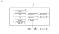
- FIG. 2 is a hardware configuration diagram of the simulation device 2. As shown in FIG. 2, RAM 12, ROM 13, storage device 14, input controller 15, display controller 16, and communication device 17 are connected to the processor 11 via a data/control bus 10. An optional input device 18 such as a keyboard, mouse, or operation buttons is connected to the input controller 15. An optional display device 19 such as an organic EL display is connected to the display controller 16.
- the processor 11 is realized by a CPU, a GPU, etc.
- the RAM 12 functions as the main memory, work area, etc. of the processor 11.
- the ROM 13 stores the BIOS, OS, etc.
- the storage device 14 stores a simulation program.
- the communication device 17 is realized by a communication module that complies with any communication standard, and transmits and receives various data to and from external devices such as the control device 7 according to the control of the processor 11.
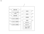
- FIG. 3 is a functional block diagram of the simulation device 2.
- the simulation device 2 When the processor 11 executes the simulation program loaded from the storage device 14 to the RAM 12, the simulation device 2 functions as a reception unit 21, a display unit 22, a transmission/reception unit 23, a storage unit 24, a screen creation unit 25, a simulation space creation unit 26, a projection processing unit 27, a 2D model selection unit 28, a 3D model selection unit 29, and a 3D model placement unit 30.
- the reception unit 21 receives user operations via the input device 18. Specifically, the reception unit 21 receives user operations for drawing a line drawing freehand in the simulation space displayed on the simulation screen.
- the display unit 22 is realized by the function of the display device 19 shown in FIG. 2.
- the display unit 22 displays the simulation screen created by the screen creation unit 25.
- the transmission/reception unit 23 is realized by the functions of the communication device 17 shown in FIG. 2.
- the transmission/reception unit 23 transmits and receives data to and from the control device 7.
- the storage unit 24 is realized by the functions of the storage device 14 shown in FIG. 2.
- the storage unit 24 stores data on an object information management table for managing object information, multiple two-dimensional models related to multiple objects managed in the object information management table, and multiple three-dimensional models related to multiple objects managed in the object information management table.
- the screen creation unit 25 creates various screens related to the simulation program. Specifically, the screen creation unit 25 creates a simulation screen.
- the simulation screen displays the simulation space created by the simulation space creation unit 26.
- the simulation space displayed on the simulation screen is a two-dimensional simulation space image projected from an arbitrary direction onto the three-dimensional simulation space.
- the simulation space creation unit 26 creates a simulation space (virtual space) in software that represents the operating space of the robot 6 in three dimensions.
- the projection processing unit 27 generates data of a two-dimensional simulation space image by projecting the three-dimensional simulation space created by the simulation space creation unit 26 from an arbitrary direction with an arbitrary position on the simulation space as the projection center position.
- the simulation space image is displayed on the simulation screen.
- the projection direction is also called the line of sight direction.
- the projection method may be parallel projection or far-sighted projection.
- the line of sight direction and the projection center position can be arbitrarily changed by a user operation on the simulation space image.
- the projection processing unit 27 repeatedly generates a simulation space image each time one of the line of sight direction and the projection center position is changed, and the simulation space image displayed on the simulation screen is repeatedly updated.
- the two-dimensional model selection unit 28 selects, from among multiple two-dimensional models, a two-dimensional model that approximates the two-dimensional line drawing drawn by the user on the simulation space image (displayed simulation space).
- the 3D model selection unit 29 selects one 3D model from the multiple 3D models that has a common object with the 2D model selected by the 2D model selection unit 28.
- the three-dimensional model placement unit 30 places the three-dimensional model selected by the three-dimensional model selection unit 29 in the simulation space. Specifically, the three-dimensional model placement unit 30 places the three-dimensional model in the simulation space based on the position of the line drawing drawn by the user on the simulation space image.
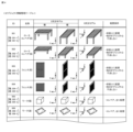
- FIG. 4 shows an example of the object information management table.
- the name of the object, the two-dimensional model of the object, the three-dimensional model of the object, and the placement conditions are associated with an ID that identifies the object.
- the two-dimensional model of an object is a three-dimensional model of the object projected from a specific line of sight direction. Even if it is the same object, two-dimensional models with different postures are distinguished from each other. For example, in FIG.
- the ID "001” is an ID that identifies a roller conveyor (high), and a two-dimensional model in which the roller conveyor (high) is arranged horizontally is distinguished from a two-dimensional model in which the roller conveyor (high) is arranged vertically, and the IDs "001-1" and "001-2" are assigned to them, respectively.
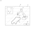
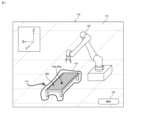
- FIG. 5 shows an example of a simulation screen.
- a simulation space image 110 is displayed on the simulation screen 100, in which an arbitrary position in the three-dimensional simulation space is set as the projection center position, and the three-dimensional simulation space is projected from the line of sight.
- the simulation space image 110 displayed on the simulation screen 100 includes a robot model image 120 in which the three-dimensional model of a robot 6 is projected from the line of sight.
- a simulation space image 110 is displayed in which the three-dimensional simulation space is projected from a predetermined line of sight direction (hereinafter referred to as a specific line of sight direction).
- a user operation is accepted in which a line drawing 130 is drawn freehand on the simulation space image 110 corresponding to the specific line of sight direction.
- the specific line of sight direction is determined so as not to be parallel to each of the three axes (X-axis, Y-axis, Z-axis) defined in the simulation space.
- the specific line of sight direction is determined to be inclined with respect to each of the three axes (X-axis, Y-axis, Z-axis) defined in the simulation space.
- the projection magnification (display magnification) and the projection center position may be predetermined in the same way as the specific line of sight direction, or may be arbitrarily set by the user.
- FIG. 6 is a supplementary diagram for explaining the two-dimensional model selection unit 28 of FIG. 3.
- a line drawing 130 is drawn on the simulation space image 110 corresponding to a specific line of sight direction.
- the two-dimensional model selection unit 28 calculates a score representing the degree of approximation of each of the multiple two-dimensional models to the line drawing 130.
- the score is calculated based on the ratio of the area of the two-dimensional model to the area defined by the line drawing 130.
- the two-dimensional model selection unit 28 repeatedly calculates the score while enlarging, reducing, and translating the two-dimensional model with respect to the line drawing 130, and the maximum score is determined as the score of the two-dimensional model.
- the two-dimensional model selection unit 28 selects one two-dimensional model 200 with the highest score from the multiple two-dimensional models. In other words, the two-dimensional model selection unit 28 selects the two-dimensional model 200 of an object having a general shape closest to the frame shape represented by the line drawing 130.
- the 2D model selection unit 28 may narrow down the 2D models to be presented to the user from among the multiple 2D models in order to have the user ultimately select one 2D model. For example, the 2D model selection unit 28 may select two or three 2D models from the multiple 2D models in descending order of score as candidates to be presented to the user, or may select all 2D models with scores higher than a predetermined value as candidates to be presented to the user.
- some users are good at drawing line drawings, while others are not. In this way, by presenting the user with several candidates that are relatively close to the line drawing drawn by the user and accepting the user's selection of one 2D model, it is possible to accommodate the variation in users' strengths and weaknesses in drawing line drawings.
- the method of calculating the score is not limited to the above.
- the score may be calculated based on the ratio of the area of the area where the area of the two-dimensional model overlaps with the area defined by the line drawing 130 to the area of the area where they do not overlap.
- a selection model that has been trained using the line drawing and the two-dimensional model to be selected by the line drawing as training data may be used to select a two-dimensional model that corresponds to the line drawing 130 drawn by the user.
- FIG. 7 is a supplementary diagram for explaining the three-dimensional model placement unit 30 of FIG. 3.
- the three-dimensional model selection unit 29 has selected the three-dimensional model 300 that shares an object (ID "002" in FIG. 4) with the two-dimensional model 200 that is most similar to the line drawing 130.
- the three-dimensional model placement unit 30 sets the orientation for placing the three-dimensional model 300 in the three-dimensional simulation space as follows. That is, the three-dimensional model placement unit 30 sets the attitude (direction) of the two-dimensional model 200 as the attitude of the three-dimensional model 300.
- the three-dimensional model placement unit 30 sets the position for placing the three-dimensional model 300 in the three-dimensional simulation space as follows. For example, the three-dimensional model placement unit 30 sets the position of the three-dimensional model 300 in the three-dimensional simulation space such that the center of gravity 300g of the projection model projected from the specific line of sight direction overlaps with the center of gravity 130g of the area defined by the line drawing 130. The three-dimensional model placement unit 30 also sets the position of the three-dimensional model 300 in the three-dimensional simulation space to a position where the projection model projected from the specific line of sight direction fits within the area defined by the line drawing 130 or overlaps with the area defined by the line drawing 130, and corresponds to the placement condition of the corresponding object of the three-dimensional model 300.
- placement conditions are associated with the objects as shown in FIG. 4.
- the placement condition "placed on the floor surface” is associated with the object “conveyor”
- the placement condition "placed on the conveyor or table” is associated with the object "work (box)”. Therefore, "position according to placement conditions” means, if the object is a conveyor, the position where the three-dimensional model of the conveyor touches the floor surface in the three-dimensional simulation space, and if the object is a workpiece, the position where the three-dimensional model of the workpiece touches the conveyor in the three-dimensional simulation space.
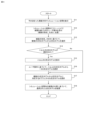
- Fig. 8 is a flowchart showing an example of the object selection and placement process by the simulation device 2 according to this embodiment.
- the object setting process is started, for example, when the start button 190 displayed on the simulation screen 100 of Fig. 5 is operated. 5, when the object setting process is started, the simulation device 2 displays a simulation screen including a simulation space image obtained by projecting a three-dimensional simulation space from a specific line of sight direction (S11), and accepts a user operation for drawing a line drawing freehand on the displayed simulation space image (S12).
- S11 line of sight direction
- step S12 information about the line drawing drawn by the user is input.
- the information about the line drawing includes the shape, size, and position on the simulation space image of the line drawing.
- the simulation device 2 selects a 2D model that approximates the line drawing from among the multiple 2D models based on the shape and size of the line drawing (S13).
- the simulation device 2 displays the two or more 2D models to receive a selection operation from the user (S15), and selects one 2D model from the two or more 2D models based on the user operation (S16).
- the simulation device 2 selects a 3D model from the multiple 3D models that has objects in common with the one 2D model (S17), and places the selected 3D model in the simulation space based on the position of the line drawing (S18).
- a user can simply draw a line drawing in the simulation space displayed on the simulation screen and place a three-dimensional model of an object that approximates the line drawing in the three-dimensional simulation space, without having to go through a series of tasks such as selecting an object from a number of objects, placing the selected object in the simulation space, and correcting the orientation and position of the placed object, as in the conventional method. Since the simple task of drawing a line drawing is all that is required, the task of placing an object in the simulation space can be simplified.
- the user does not need to draw the line drawing three-dimensionally, but can simply draw it two-dimensionally while imagining the general shape of the object when viewed from a specific line of sight, which saves the user the effort of drawing the line drawing and reduces variation in the drawing skills of different users.
- the two-dimensional model selection unit 28 selects a two-dimensional model that is similar to the line drawing from among multiple two-dimensional models.
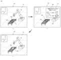
- the placement conditions associated with the object may be taken into consideration. For example, as shown in FIG. 9(a), when a line drawing 140 is drawn on a two-dimensional model (conveyor model) 400 of a conveyor, the two-dimensional model selection unit 28 refers to the object information management table in FIG. 4, selects two-dimensional models of two objects (IDs "005" and "006") that are limited to being on the conveyor as a placement condition, as placement candidates, and calculates a score representing the degree of approximation to the line drawing 140 for each of the selected two-dimensional models.
- the two-dimensional model selection unit 28 narrows down the multiple two-dimensional models based on the objects around the line drawing 140. If the scores are the same, a selection window 500 that accepts a selection operation from the user is displayed on the simulation screen 100, as shown in FIG. 9(b). Then, as shown in FIG. 9C, the two-dimensional model selection unit 28 selects the two-dimensional model selected by the user operation in the selection window 500 as the two-dimensional model 220 to be placed in the simulation space image 110. Then, the selected two-dimensional model 220 is placed in the simulation space image 110 based on the position of the line drawing 140.
- the two-dimensional model selection unit 28 can determine whether the line drawing 140 is drawn on the conveyor model 400 based on whether at least a part of the line drawing 140 overlaps with the conveyor model 400.
- the two-dimensional model selection unit 28 may determine a two-dimensional model (including a floor) specified by a click operation before drawing the line drawing as an object on which an object corresponding to the line drawing is placed. For example, when the conveyor model 400 is specified by a click operation or the like and then the line drawing 140 is drawn, the two-dimensional model selection unit 28 can determine that the object corresponding to the line drawing 140 is an object to be placed on the conveyor.
- the three-dimensional model placement unit 30 places the three-dimensional model selected by the three-dimensional model selection unit 29 in the simulation space based on the position of the line drawing drawn by the user on the simulation space image.
- rules for limiting the placement position of the three-dimensional model of the object corresponding to the line drawing may be set in advance.
- the three-dimensional model placement unit 30 determines an object selected by a click operation or the like by the user before the line drawing is drawn as a target for placing the three-dimensional model of the object corresponding to the line drawing.
- the three-dimensional model placement unit 30 places the three-dimensional model of the object corresponding to the line drawing in a position that contacts the conveying surface of the three-dimensional model of the conveyor in the simulation space.
- the three-dimensional model placement unit 30 places the three-dimensional model of the object corresponding to the line drawing in a position that contacts the floor surface in the simulation space.
- the 3D model placement unit 30 by setting the above rules in the 3D model placement process by the 3D model placement unit 30, even if a 2D model overlaps in the simulation space image in which the line drawing is drawn, the 3D model of the object corresponding to the line drawing can be placed in the position desired by the user in the 3D simulation space.
- a three-dimensional model is ultimately placed in the simulation space, but in cases such as when simply considering the placement of each device constituting a robot system, sufficient consideration can be made only on a two-dimensional simulation space image corresponding to a specific line of sight direction.
- the simulation device 2' only needs to have a storage unit 24 that stores data on a plurality of two-dimensional models corresponding to a plurality of objects as candidates to be placed in the simulation space, a display unit 22 that displays the simulation space, a reception unit 21 that receives a user operation for drawing a line drawing freehand in the simulation space, a two-dimensional model selection unit 28 that selects a two-dimensional model that approximates the line drawing from a plurality of two-dimensional models, and a two-dimensional model placement unit 31 that places the two-dimensional model selected by the two-dimensional model selection unit 28 in the simulation space displayed on the display unit 22 based on the position of the line drawing.
- the two-dimensional model placement unit 31 corresponds to the three-dimensional model placement unit 30 of the simulation device 2 according to this embodiment. In other words, the two-dimensional model placement unit 31 places the two-dimensional model on the simulation space image so as to achieve a positional relationship when the score is highest.
- the data of the three-dimensional model is stored in the storage unit 24 in advance.
- the simulation device may have a function as a three-dimensional model creation unit that creates data of the three-dimensional model.
- the storage unit stores information on a reference object shape (reference object shape) and dimensions in association with object information, and when an object that approximates a line drawing is determined by the processing of the two-dimensional model selection unit 28, the three-dimensional model creation unit creates a simple three-dimensional model of the object by combining basic three-dimensional models such as a cube, a rectangular parallelepiped, a sphere, and a cylinder based on the shape and size of the drawn object and the reference object shape according to the dimensional information of the object.
- basic three-dimensional models such as a cube, a rectangular parallelepiped, a sphere, and a cylinder based on the shape and size of the drawn object and the reference object shape according to the dimensional information of the object.
- the simulation device 2 includes a memory unit 24 that stores data of a plurality of three-dimensional models corresponding to a plurality of objects as candidates to be placed in the simulation space, and data of a plurality of two-dimensional models corresponding to the plurality of objects, a display unit 22 that displays the simulation space, a reception unit 21 that receives user operations to draw a line drawing freehand in the simulation space, a two-dimensional model selection unit 28 that selects a two-dimensional model that approximates the line drawing from the plurality of two-dimensional models, a three-dimensional model selection unit 29 that selects a three-dimensional model of an object corresponding to the selected two-dimensional model from the plurality of three-dimensional models, and a placement unit 30 that places the selected three-dimensional model in the simulation space based on the position of the line drawing.
- the 2D model selection unit 28 selects two or more 2D models that approximate a line drawing from a plurality of 2D models, and selects one 2D model based on a user operation from the two or more 2D models.
- the 2D model selection unit 28 narrows down a plurality of 2D models based on object information arranged around the line drawing, and selects a 2D model that approximates the line drawing from the narrowed down 2D models.
- the plurality of two-dimensional models includes a plurality of types of two-dimensional models of the same object having different poses.
- the display unit 22 displays the simulation space by projecting it from a predetermined line of sight direction, and the two-dimensional model is a model obtained by projecting a three-dimensional model having common objects from the line of sight direction.
- the simulation device 2 includes a memory unit 24 that stores data on a plurality of two-dimensional models corresponding to a plurality of objects as candidates for placement in the simulation space, a display unit 22 that displays the simulation space, a reception unit 21 that receives user operations for drawing a line drawing freehand in the simulation space, a two-dimensional model selection unit 28 that selects a two-dimensional model that approximates the line drawing from the plurality of two-dimensional models, and a two-dimensional model placement unit that places the selected two-dimensional model in the simulation space displayed on the display unit 22 based on the position of the line drawing.
- the simulation program causes a computer that stores data of a plurality of three-dimensional models each corresponding to a plurality of objects as candidates to be placed in the simulation space and data of a plurality of two-dimensional models each corresponding to the plurality of objects to implement the following: means for displaying a simulation space; means for accepting user operations for drawing a line drawing freehand within the simulation space; means for selecting a two-dimensional model that approximates the line drawing from the plurality of two-dimensional models; means for selecting a three-dimensional model of an object corresponding to the two-dimensional model from the plurality of three-dimensional models; and means for placing the selected three-dimensional model within the simulation space based on the position of the line drawing.
- 1...simulation system 2...simulation device, 6...robot, 7...control device, 10...data/control bus, 11...processor, 12...RAM, 13...ROM, 14...storage device, 15...input controller, 16...display controller, 17...communication device, 18...input device, 19...display device, 21...reception unit, 22...display unit, 23...transmission/reception unit, 24...storage unit, 25...screen creation unit, 26...simulation space creation unit, 27...projection processing unit, 28...2D model selection unit, 29...3D model selection unit, 30...3D model placement unit.
Landscapes
- Engineering & Computer Science (AREA)
- Computer Graphics (AREA)
- Computer Hardware Design (AREA)
- General Engineering & Computer Science (AREA)
- Software Systems (AREA)
- Physics & Mathematics (AREA)
- General Physics & Mathematics (AREA)
- Theoretical Computer Science (AREA)
- Architecture (AREA)
- Processing Or Creating Images (AREA)
- Image Generation (AREA)
Priority Applications (5)
| Application Number | Priority Date | Filing Date | Title |
|---|---|---|---|
| DE112023006356.7T DE112023006356T5 (de) | 2023-07-14 | 2023-07-14 | Simulationsvorrichtung und Simulationsprogramm |
| JP2025533731A JPWO2025017789A1 (cg-RX-API-DMAC7.html) | 2023-07-14 | 2023-07-14 | |
| CN202380100057.6A CN121464466A (zh) | 2023-07-14 | 2023-07-14 | 模拟装置以及模拟程序 |
| PCT/JP2023/026096 WO2025017789A1 (ja) | 2023-07-14 | 2023-07-14 | シミュレーション装置及びシミュレーションプログラム |
| TW113124896A TW202503448A (zh) | 2023-07-14 | 2024-07-03 | 模擬裝置及模擬程式 |
Applications Claiming Priority (1)
| Application Number | Priority Date | Filing Date | Title |
|---|---|---|---|
| PCT/JP2023/026096 WO2025017789A1 (ja) | 2023-07-14 | 2023-07-14 | シミュレーション装置及びシミュレーションプログラム |
Publications (1)
| Publication Number | Publication Date |
|---|---|
| WO2025017789A1 true WO2025017789A1 (ja) | 2025-01-23 |
Family
ID=94281927
Family Applications (1)
| Application Number | Title | Priority Date | Filing Date |
|---|---|---|---|
| PCT/JP2023/026096 Ceased WO2025017789A1 (ja) | 2023-07-14 | 2023-07-14 | シミュレーション装置及びシミュレーションプログラム |
Country Status (5)
| Country | Link |
|---|---|
| JP (1) | JPWO2025017789A1 (cg-RX-API-DMAC7.html) |
| CN (1) | CN121464466A (cg-RX-API-DMAC7.html) |
| DE (1) | DE112023006356T5 (cg-RX-API-DMAC7.html) |
| TW (1) | TW202503448A (cg-RX-API-DMAC7.html) |
| WO (1) | WO2025017789A1 (cg-RX-API-DMAC7.html) |
Cited By (1)
| Publication number | Priority date | Publication date | Assignee | Title |
|---|---|---|---|---|
| CN120680516A (zh) * | 2025-07-15 | 2025-09-23 | 五八智能科技(杭州)有限公司 | 一种低重力环境下机器人搬运方法、系统和存储介质 |
Citations (3)
| Publication number | Priority date | Publication date | Assignee | Title |
|---|---|---|---|---|
| JP2010118048A (ja) * | 2008-11-12 | 2010-05-27 | Honda Motor Co Ltd | 描画支援装置、描画支援プログラム、描画支援方法 |
| JP2011002875A (ja) * | 2009-06-16 | 2011-01-06 | Nippon Telegr & Teleph Corp <Ntt> | 描画支援装置,描画支援方法および描画支援プログラム |
| US20190370617A1 (en) * | 2018-06-04 | 2019-12-05 | Adobe Inc. | Sketch Completion Using Machine Learning |
-
2023
- 2023-07-14 WO PCT/JP2023/026096 patent/WO2025017789A1/ja not_active Ceased
- 2023-07-14 JP JP2025533731A patent/JPWO2025017789A1/ja active Pending
- 2023-07-14 CN CN202380100057.6A patent/CN121464466A/zh active Pending
- 2023-07-14 DE DE112023006356.7T patent/DE112023006356T5/de active Pending
-
2024
- 2024-07-03 TW TW113124896A patent/TW202503448A/zh unknown
Patent Citations (3)
| Publication number | Priority date | Publication date | Assignee | Title |
|---|---|---|---|---|
| JP2010118048A (ja) * | 2008-11-12 | 2010-05-27 | Honda Motor Co Ltd | 描画支援装置、描画支援プログラム、描画支援方法 |
| JP2011002875A (ja) * | 2009-06-16 | 2011-01-06 | Nippon Telegr & Teleph Corp <Ntt> | 描画支援装置,描画支援方法および描画支援プログラム |
| US20190370617A1 (en) * | 2018-06-04 | 2019-12-05 | Adobe Inc. | Sketch Completion Using Machine Learning |
Non-Patent Citations (1)
| Title |
|---|
| SHIN, HYO-JONG : "Interactive Design of 3D Scenes from Freehand Sketches.", 14TH WORKSHOP ON INTERACTIVE SYSTEMS AND SOFTWARE., 8 December 2006 (2006-12-08), XP093263365 * |
Cited By (1)
| Publication number | Priority date | Publication date | Assignee | Title |
|---|---|---|---|---|
| CN120680516A (zh) * | 2025-07-15 | 2025-09-23 | 五八智能科技(杭州)有限公司 | 一种低重力环境下机器人搬运方法、系统和存储介质 |
Also Published As
| Publication number | Publication date |
|---|---|
| CN121464466A (zh) | 2026-02-03 |
| JPWO2025017789A1 (cg-RX-API-DMAC7.html) | 2025-01-23 |
| TW202503448A (zh) | 2025-01-16 |
| DE112023006356T5 (de) | 2026-03-12 |
Similar Documents
| Publication | Publication Date | Title |
|---|---|---|
| US10241582B2 (en) | Information processing device, information processing method, and program for graphical user interface | |
| EP0856786B1 (en) | Window Displaying apparatus and method | |
| JP4465142B2 (ja) | ウィンドウ表示制御プログラム、ウィンドウ表示制御方法およびウィンドウ表示制御装置 | |
| US20250252690A1 (en) | Display of virtual tablets in extended reality environments | |
| CN111708504A (zh) | 一种扩展屏幕的显示方法 | |
| US11978152B2 (en) | Computer-assisted graphical development tools | |
| JP3559335B2 (ja) | 三次元画像処理装置 | |
| JP6121496B2 (ja) | ヘッドマウントディスプレイシステムを制御するプログラム | |
| TW202503448A (zh) | 模擬裝置及模擬程式 | |
| JP7353418B1 (ja) | 画像を生成するためのプログラム、方法、画像生成装置、及びゲームシステム | |
| TWI503800B (zh) | 建築模型影像顯示系統及其方法 | |
| JPWO2008029466A1 (ja) | チャット端末装置、チャットシステム | |
| JP3413145B2 (ja) | 仮想空間の編集方法及び仮想空間の編集装置 | |
| Bowman et al. | Evaluating the need for display-specific and device-specific 3D interaction techniques | |
| CN212256285U (zh) | 一种扩展屏幕显示系统 | |
| US20130090895A1 (en) | Device and associated methodology for manipulating three-dimensional objects | |
| JPH0614336B2 (ja) | 設計支援方法 | |
| WO2021255864A1 (ja) | 情報処理装置、情報処理方法及びプログラム | |
| JP2017126240A (ja) | 3次元モデル表示システムおよび表示方法 | |
| JP2000322600A (ja) | インターネット3次元マルチウィンドウ制御表示システムおよびインターネット3次元マルチウィンドウ制御表示方法 | |
| US20240345712A1 (en) | Method and system for summoning adaptive toolbar items and digital assets associated therewith on a large format screen within a digital collaboration environment | |
| JP2021174105A (ja) | 画像表示方法、画像表示システム、及び画像表示プログラム | |
| JP6353795B2 (ja) | 端末結合表示システム及び端末結合表示プログラム | |
| JP2882884B2 (ja) | 図形表示装置 | |
| JP6434894B2 (ja) | 端末合体表示システム及び端末合体表示プログラム |
Legal Events
| Date | Code | Title | Description |
|---|---|---|---|
| 121 | Ep: the epo has been informed by wipo that ep was designated in this application |
Ref document number: 23945794 Country of ref document: EP Kind code of ref document: A1 |
|
| ENP | Entry into the national phase |
Ref document number: 2025533731 Country of ref document: JP Kind code of ref document: A |
|
| WWE | Wipo information: entry into national phase |
Ref document number: 112023006356 Country of ref document: DE |
|
| WWP | Wipo information: published in national office |
Ref document number: 112023006356 Country of ref document: DE |
|
| 122 | Ep: pct application non-entry in european phase |
Ref document number: 23945794 Country of ref document: EP Kind code of ref document: A1 |