WO2025013602A1 - 複合シート - Google Patents
複合シート Download PDFInfo
- Publication number
- WO2025013602A1 WO2025013602A1 PCT/JP2024/022786 JP2024022786W WO2025013602A1 WO 2025013602 A1 WO2025013602 A1 WO 2025013602A1 JP 2024022786 W JP2024022786 W JP 2024022786W WO 2025013602 A1 WO2025013602 A1 WO 2025013602A1
- Authority
- WO
- WIPO (PCT)
- Prior art keywords
- composite sheet
- mass
- less
- fibers
- raw material
- Prior art date
- Legal status (The legal status is an assumption and is not a legal conclusion. Google has not performed a legal analysis and makes no representation as to the accuracy of the status listed.)
- Ceased
Links
Classifications
-
- D—TEXTILES; PAPER
- D04—BRAIDING; LACE-MAKING; KNITTING; TRIMMINGS; NON-WOVEN FABRICS
- D04H—MAKING TEXTILE FABRICS, e.g. FROM FIBRES OR FILAMENTARY MATERIAL; FABRICS MADE BY SUCH PROCESSES OR APPARATUS, e.g. FELTS, NON-WOVEN FABRICS; COTTON-WOOL; WADDING ; NON-WOVEN FABRICS FROM STAPLE FIBRES, FILAMENTS OR YARNS, BONDED WITH AT LEAST ONE WEB-LIKE MATERIAL DURING THEIR CONSOLIDATION
- D04H1/00—Non-woven fabrics formed wholly or mainly of staple fibres or like relatively short fibres
- D04H1/40—Non-woven fabrics formed wholly or mainly of staple fibres or like relatively short fibres from fleeces or layers composed of fibres without existing or potential cohesive properties
- D04H1/407—Non-woven fabrics formed wholly or mainly of staple fibres or like relatively short fibres from fleeces or layers composed of fibres without existing or potential cohesive properties containing absorbing substances, e.g. activated carbon
-
- B—PERFORMING OPERATIONS; TRANSPORTING
- B01—PHYSICAL OR CHEMICAL PROCESSES OR APPARATUS IN GENERAL
- B01D—SEPARATION
- B01D53/00—Separation of gases or vapours; Recovering vapours of volatile solvents from gases; Chemical or biological purification of waste gases, e.g. engine exhaust gases, smoke, fumes, flue gases, aerosols
- B01D53/02—Separation of gases or vapours; Recovering vapours of volatile solvents from gases; Chemical or biological purification of waste gases, e.g. engine exhaust gases, smoke, fumes, flue gases, aerosols by adsorption, e.g. preparative gas chromatography
-
- B—PERFORMING OPERATIONS; TRANSPORTING
- B01—PHYSICAL OR CHEMICAL PROCESSES OR APPARATUS IN GENERAL
- B01J—CHEMICAL OR PHYSICAL PROCESSES, e.g. CATALYSIS OR COLLOID CHEMISTRY; THEIR RELEVANT APPARATUS
- B01J20/00—Solid sorbent compositions or filter aid compositions; Sorbents for chromatography; Processes for preparing, regenerating or reactivating thereof
- B01J20/22—Solid sorbent compositions or filter aid compositions; Sorbents for chromatography; Processes for preparing, regenerating or reactivating thereof comprising organic material
- B01J20/223—Solid sorbent compositions or filter aid compositions; Sorbents for chromatography; Processes for preparing, regenerating or reactivating thereof comprising organic material containing metals, e.g. organo-metallic compounds, coordination complexes
- B01J20/226—Coordination polymers, e.g. metal-organic frameworks [MOF], zeolitic imidazolate frameworks [ZIF]
-
- B—PERFORMING OPERATIONS; TRANSPORTING
- B01—PHYSICAL OR CHEMICAL PROCESSES OR APPARATUS IN GENERAL
- B01J—CHEMICAL OR PHYSICAL PROCESSES, e.g. CATALYSIS OR COLLOID CHEMISTRY; THEIR RELEVANT APPARATUS
- B01J20/00—Solid sorbent compositions or filter aid compositions; Sorbents for chromatography; Processes for preparing, regenerating or reactivating thereof
- B01J20/28—Solid sorbent compositions or filter aid compositions; Sorbents for chromatography; Processes for preparing, regenerating or reactivating thereof characterised by their form or physical properties
- B01J20/28014—Solid sorbent compositions or filter aid compositions; Sorbents for chromatography; Processes for preparing, regenerating or reactivating thereof characterised by their form or physical properties characterised by their form
- B01J20/28033—Membrane, sheet, cloth, pad, lamellar or mat
- B01J20/28038—Membranes or mats made from fibers or filaments
-
- B—PERFORMING OPERATIONS; TRANSPORTING
- B01—PHYSICAL OR CHEMICAL PROCESSES OR APPARATUS IN GENERAL
- B01J—CHEMICAL OR PHYSICAL PROCESSES, e.g. CATALYSIS OR COLLOID CHEMISTRY; THEIR RELEVANT APPARATUS
- B01J20/00—Solid sorbent compositions or filter aid compositions; Sorbents for chromatography; Processes for preparing, regenerating or reactivating thereof
- B01J20/30—Processes for preparing, regenerating, or reactivating
- B01J20/3078—Thermal treatment, e.g. calcining or pyrolizing
-
- B—PERFORMING OPERATIONS; TRANSPORTING
- B01—PHYSICAL OR CHEMICAL PROCESSES OR APPARATUS IN GENERAL
- B01J—CHEMICAL OR PHYSICAL PROCESSES, e.g. CATALYSIS OR COLLOID CHEMISTRY; THEIR RELEVANT APPARATUS
- B01J20/00—Solid sorbent compositions or filter aid compositions; Sorbents for chromatography; Processes for preparing, regenerating or reactivating thereof
- B01J20/30—Processes for preparing, regenerating, or reactivating
- B01J20/32—Impregnating or coating ; Solid sorbent compositions obtained from processes involving impregnating or coating
- B01J20/3202—Impregnating or coating ; Solid sorbent compositions obtained from processes involving impregnating or coating characterised by the carrier, support or substrate used for impregnation or coating
- B01J20/3206—Organic carriers, supports or substrates
- B01J20/3208—Polymeric carriers, supports or substrates
- B01J20/3212—Polymeric carriers, supports or substrates consisting of a polymer obtained by reactions otherwise than involving only carbon to carbon unsaturated bonds
-
- B—PERFORMING OPERATIONS; TRANSPORTING
- B01—PHYSICAL OR CHEMICAL PROCESSES OR APPARATUS IN GENERAL
- B01J—CHEMICAL OR PHYSICAL PROCESSES, e.g. CATALYSIS OR COLLOID CHEMISTRY; THEIR RELEVANT APPARATUS
- B01J20/00—Solid sorbent compositions or filter aid compositions; Sorbents for chromatography; Processes for preparing, regenerating or reactivating thereof
- B01J20/30—Processes for preparing, regenerating, or reactivating
- B01J20/32—Impregnating or coating ; Solid sorbent compositions obtained from processes involving impregnating or coating
- B01J20/3231—Impregnating or coating ; Solid sorbent compositions obtained from processes involving impregnating or coating characterised by the coating or impregnating layer
- B01J20/3242—Layers with a functional group, e.g. an affinity material, a ligand, a reactant or a complexing group
- B01J20/3244—Non-macromolecular compounds
- B01J20/3265—Non-macromolecular compounds with an organic functional group containing a metal, e.g. a metal affinity ligand
-
- B—PERFORMING OPERATIONS; TRANSPORTING
- B01—PHYSICAL OR CHEMICAL PROCESSES OR APPARATUS IN GENERAL
- B01J—CHEMICAL OR PHYSICAL PROCESSES, e.g. CATALYSIS OR COLLOID CHEMISTRY; THEIR RELEVANT APPARATUS
- B01J20/00—Solid sorbent compositions or filter aid compositions; Sorbents for chromatography; Processes for preparing, regenerating or reactivating thereof
- B01J20/30—Processes for preparing, regenerating, or reactivating
- B01J20/32—Impregnating or coating ; Solid sorbent compositions obtained from processes involving impregnating or coating
- B01J20/3291—Characterised by the shape of the carrier, the coating or the obtained coated product
- B01J20/3293—Coatings on a core, the core being particle or fiber shaped, e.g. encapsulated particles, coated fibers
-
- B—PERFORMING OPERATIONS; TRANSPORTING
- B01—PHYSICAL OR CHEMICAL PROCESSES OR APPARATUS IN GENERAL
- B01J—CHEMICAL OR PHYSICAL PROCESSES, e.g. CATALYSIS OR COLLOID CHEMISTRY; THEIR RELEVANT APPARATUS
- B01J20/00—Solid sorbent compositions or filter aid compositions; Sorbents for chromatography; Processes for preparing, regenerating or reactivating thereof
- B01J20/30—Processes for preparing, regenerating, or reactivating
- B01J20/32—Impregnating or coating ; Solid sorbent compositions obtained from processes involving impregnating or coating
- B01J20/3291—Characterised by the shape of the carrier, the coating or the obtained coated product
- B01J20/3295—Coatings made of particles, nanoparticles, fibers, nanofibers
-
- C—CHEMISTRY; METALLURGY
- C03—GLASS; MINERAL OR SLAG WOOL
- C03C—CHEMICAL COMPOSITION OF GLASSES, GLAZES OR VITREOUS ENAMELS; SURFACE TREATMENT OF GLASS; SURFACE TREATMENT OF FIBRES OR FILAMENTS MADE FROM GLASS, MINERALS OR SLAGS; JOINING GLASS TO GLASS OR OTHER MATERIALS
- C03C25/00—Surface treatment of fibres or filaments made from glass, minerals or slags
- C03C25/10—Coating
- C03C25/465—Coatings containing composite materials
- C03C25/47—Coatings containing composite materials containing particles, fibres or flakes, e.g. in a continuous phase
-
- D—TEXTILES; PAPER
- D04—BRAIDING; LACE-MAKING; KNITTING; TRIMMINGS; NON-WOVEN FABRICS
- D04H—MAKING TEXTILE FABRICS, e.g. FROM FIBRES OR FILAMENTARY MATERIAL; FABRICS MADE BY SUCH PROCESSES OR APPARATUS, e.g. FELTS, NON-WOVEN FABRICS; COTTON-WOOL; WADDING ; NON-WOVEN FABRICS FROM STAPLE FIBRES, FILAMENTS OR YARNS, BONDED WITH AT LEAST ONE WEB-LIKE MATERIAL DURING THEIR CONSOLIDATION
- D04H1/00—Non-woven fabrics formed wholly or mainly of staple fibres or like relatively short fibres
- D04H1/04—Non-woven fabrics formed wholly or mainly of staple fibres or like relatively short fibres from fleeces or layers composed of fibres having existing or potential cohesive properties, e.g. natural fibres, prestretched or fibrillated artificial fibres
- D04H1/26—Wood pulp
-
- D—TEXTILES; PAPER
- D04—BRAIDING; LACE-MAKING; KNITTING; TRIMMINGS; NON-WOVEN FABRICS
- D04H—MAKING TEXTILE FABRICS, e.g. FROM FIBRES OR FILAMENTARY MATERIAL; FABRICS MADE BY SUCH PROCESSES OR APPARATUS, e.g. FELTS, NON-WOVEN FABRICS; COTTON-WOOL; WADDING ; NON-WOVEN FABRICS FROM STAPLE FIBRES, FILAMENTS OR YARNS, BONDED WITH AT LEAST ONE WEB-LIKE MATERIAL DURING THEIR CONSOLIDATION
- D04H1/00—Non-woven fabrics formed wholly or mainly of staple fibres or like relatively short fibres
- D04H1/40—Non-woven fabrics formed wholly or mainly of staple fibres or like relatively short fibres from fleeces or layers composed of fibres without existing or potential cohesive properties
- D04H1/42—Non-woven fabrics formed wholly or mainly of staple fibres or like relatively short fibres from fleeces or layers composed of fibres without existing or potential cohesive properties characterised by the use of certain kinds of fibres insofar as this use has no preponderant influence on the consolidation of the fleece
- D04H1/425—Cellulose series
-
- D—TEXTILES; PAPER
- D04—BRAIDING; LACE-MAKING; KNITTING; TRIMMINGS; NON-WOVEN FABRICS
- D04H—MAKING TEXTILE FABRICS, e.g. FROM FIBRES OR FILAMENTARY MATERIAL; FABRICS MADE BY SUCH PROCESSES OR APPARATUS, e.g. FELTS, NON-WOVEN FABRICS; COTTON-WOOL; WADDING ; NON-WOVEN FABRICS FROM STAPLE FIBRES, FILAMENTS OR YARNS, BONDED WITH AT LEAST ONE WEB-LIKE MATERIAL DURING THEIR CONSOLIDATION
- D04H1/00—Non-woven fabrics formed wholly or mainly of staple fibres or like relatively short fibres
- D04H1/40—Non-woven fabrics formed wholly or mainly of staple fibres or like relatively short fibres from fleeces or layers composed of fibres without existing or potential cohesive properties
- D04H1/42—Non-woven fabrics formed wholly or mainly of staple fibres or like relatively short fibres from fleeces or layers composed of fibres without existing or potential cohesive properties characterised by the use of certain kinds of fibres insofar as this use has no preponderant influence on the consolidation of the fleece
- D04H1/4382—Stretched reticular film fibres; Composite fibres; Mixed fibres; Ultrafine fibres; Fibres for artificial leather
- D04H1/43835—Mixed fibres, e.g. at least two chemically different fibres or fibre blends
-
- D—TEXTILES; PAPER
- D04—BRAIDING; LACE-MAKING; KNITTING; TRIMMINGS; NON-WOVEN FABRICS
- D04H—MAKING TEXTILE FABRICS, e.g. FROM FIBRES OR FILAMENTARY MATERIAL; FABRICS MADE BY SUCH PROCESSES OR APPARATUS, e.g. FELTS, NON-WOVEN FABRICS; COTTON-WOOL; WADDING ; NON-WOVEN FABRICS FROM STAPLE FIBRES, FILAMENTS OR YARNS, BONDED WITH AT LEAST ONE WEB-LIKE MATERIAL DURING THEIR CONSOLIDATION
- D04H1/00—Non-woven fabrics formed wholly or mainly of staple fibres or like relatively short fibres
- D04H1/40—Non-woven fabrics formed wholly or mainly of staple fibres or like relatively short fibres from fleeces or layers composed of fibres without existing or potential cohesive properties
- D04H1/54—Non-woven fabrics formed wholly or mainly of staple fibres or like relatively short fibres from fleeces or layers composed of fibres without existing or potential cohesive properties by welding together the fibres, e.g. by partially melting or dissolving
- D04H1/541—Composite fibres, e.g. sheath-core, sea-island or side-by-side; Mixed fibres
- D04H1/5412—Composite fibres, e.g. sheath-core, sea-island or side-by-side; Mixed fibres sheath-core
-
- D—TEXTILES; PAPER
- D04—BRAIDING; LACE-MAKING; KNITTING; TRIMMINGS; NON-WOVEN FABRICS
- D04H—MAKING TEXTILE FABRICS, e.g. FROM FIBRES OR FILAMENTARY MATERIAL; FABRICS MADE BY SUCH PROCESSES OR APPARATUS, e.g. FELTS, NON-WOVEN FABRICS; COTTON-WOOL; WADDING ; NON-WOVEN FABRICS FROM STAPLE FIBRES, FILAMENTS OR YARNS, BONDED WITH AT LEAST ONE WEB-LIKE MATERIAL DURING THEIR CONSOLIDATION
- D04H1/00—Non-woven fabrics formed wholly or mainly of staple fibres or like relatively short fibres
- D04H1/70—Non-woven fabrics formed wholly or mainly of staple fibres or like relatively short fibres characterised by the method of forming fleeces or layers, e.g. reorientation of fibres
- D04H1/72—Non-woven fabrics formed wholly or mainly of staple fibres or like relatively short fibres characterised by the method of forming fleeces or layers, e.g. reorientation of fibres the fibres being randomly arranged
- D04H1/732—Non-woven fabrics formed wholly or mainly of staple fibres or like relatively short fibres characterised by the method of forming fleeces or layers, e.g. reorientation of fibres the fibres being randomly arranged by fluid current, e.g. air-lay
-
- D—TEXTILES; PAPER
- D06—TREATMENT OF TEXTILES OR THE LIKE; LAUNDERING; FLEXIBLE MATERIALS NOT OTHERWISE PROVIDED FOR
- D06M—TREATMENT, NOT PROVIDED FOR ELSEWHERE IN CLASS D06, OF FIBRES, THREADS, YARNS, FABRICS, FEATHERS OR FIBROUS GOODS MADE FROM SUCH MATERIALS
- D06M13/00—Treating fibres, threads, yarns, fabrics or fibrous goods made from such materials, with non-macromolecular organic compounds; Such treatment combined with mechanical treatment
- D06M13/50—Treating fibres, threads, yarns, fabrics or fibrous goods made from such materials, with non-macromolecular organic compounds; Such treatment combined with mechanical treatment with organometallic compounds; with organic compounds containing boron, silicon, selenium or tellurium atoms
-
- D—TEXTILES; PAPER
- D06—TREATMENT OF TEXTILES OR THE LIKE; LAUNDERING; FLEXIBLE MATERIALS NOT OTHERWISE PROVIDED FOR
- D06M—TREATMENT, NOT PROVIDED FOR ELSEWHERE IN CLASS D06, OF FIBRES, THREADS, YARNS, FABRICS, FEATHERS OR FIBROUS GOODS MADE FROM SUCH MATERIALS
- D06M13/00—Treating fibres, threads, yarns, fabrics or fibrous goods made from such materials, with non-macromolecular organic compounds; Such treatment combined with mechanical treatment
- D06M13/50—Treating fibres, threads, yarns, fabrics or fibrous goods made from such materials, with non-macromolecular organic compounds; Such treatment combined with mechanical treatment with organometallic compounds; with organic compounds containing boron, silicon, selenium or tellurium atoms
- D06M13/503—Treating fibres, threads, yarns, fabrics or fibrous goods made from such materials, with non-macromolecular organic compounds; Such treatment combined with mechanical treatment with organometallic compounds; with organic compounds containing boron, silicon, selenium or tellurium atoms without bond between a carbon atom and a metal or a boron, silicon, selenium or tellurium atom
-
- D—TEXTILES; PAPER
- D06—TREATMENT OF TEXTILES OR THE LIKE; LAUNDERING; FLEXIBLE MATERIALS NOT OTHERWISE PROVIDED FOR
- D06M—TREATMENT, NOT PROVIDED FOR ELSEWHERE IN CLASS D06, OF FIBRES, THREADS, YARNS, FABRICS, FEATHERS OR FIBROUS GOODS MADE FROM SUCH MATERIALS
- D06M23/00—Treatment of fibres, threads, yarns, fabrics or fibrous goods made from such materials, characterised by the process
- D06M23/10—Processes in which the treating agent is dissolved or dispersed in organic solvents; Processes for the recovery of organic solvents thereof
-
- B—PERFORMING OPERATIONS; TRANSPORTING
- B01—PHYSICAL OR CHEMICAL PROCESSES OR APPARATUS IN GENERAL
- B01D—SEPARATION
- B01D2253/00—Adsorbents used in seperation treatment of gases and vapours
- B01D2253/20—Organic adsorbents
- B01D2253/204—Metal organic frameworks (MOF's)
-
- B—PERFORMING OPERATIONS; TRANSPORTING
- B01—PHYSICAL OR CHEMICAL PROCESSES OR APPARATUS IN GENERAL
- B01D—SEPARATION
- B01D2253/00—Adsorbents used in seperation treatment of gases and vapours
- B01D2253/25—Coated, impregnated or composite adsorbents
-
- B—PERFORMING OPERATIONS; TRANSPORTING
- B01—PHYSICAL OR CHEMICAL PROCESSES OR APPARATUS IN GENERAL
- B01D—SEPARATION
- B01D2257/00—Components to be removed
- B01D2257/50—Carbon oxides
- B01D2257/504—Carbon dioxide
Definitions
- the present invention relates to a composite sheet in which a metal-organic framework is supported on a sheet substrate.
- MOFs Metal organic frameworks
- MOFs have attracted attention as high-performance gas adsorption materials due to their uniform pore size, high specific surface area, and high separation performance.
- MOFs are known to be difficult to handle on their own because they are fine powders on the micron scale.
- technology that supports MOFs on a substrate such as a nonwoven fabric, making it possible to handle large quantities of MOFs at once (see, for example, Patent Document 1).
- MOFs In order to improve gas adsorption performance, it is necessary to support a large amount of MOFs on the nonwoven fabric. To achieve this, it is advantageous to support MOFs not only on the surface of the nonwoven fabric but also inside it. However, with common methods such as spraying MOF particles on the nonwoven fabric or impregnating the nonwoven fabric with a MOF dispersion, the individual MOF particles tend to remain on the surface of the nonwoven fabric rather than penetrating into the interior of the fabric.
- the objective of the present invention is to provide a composite sheet having high gas adsorption performance, in which a metal-organic framework is supported on a sheet substrate made of fibers.
- a metal organic framework is dispersed in a sheet base material made of fibers.
- the metal-organic framework is supported on the surface of the fiber.
- the ratio of the mass of the metal organic framework to the mass of the entire composite sheet is 80 mass % or more.
- the surface coverage by the metal-organic framework of the fibers constituting the central portion in the thickness direction of the composite sheet is 60% or more.
- the metal organic framework has a surface exposure rate of 50% or more.
- a composite sheet is produced in which a metal organic framework is supported in a sheet base material made of fibers.
- a first raw material solution containing one of metal ions and organic ligands that are raw materials for the metal organic framework, and a second raw material solution containing the other are prepared.
- the sheet substrate is impregnated with the first raw material solution.
- the sheet base material is impregnated with the second raw material solution before the first raw material solution impregnated into the sheet base material is dried.
- the sheet base material impregnated with the second raw material solution is dried.
- the dried sheet substrate is subjected to a heat treatment.
- the ratio of the mass of the metal organic framework to the mass of the entire composite sheet after the heat treatment is 80 mass% or more. impregnating the sheet substrate with the first raw material solution; impregnating the sheet base material with the second raw material solution before the first raw material solution impregnated into the sheet base material dries; The step of drying the sheet substrate impregnated with the second raw material solution is repeated.
- a metal-organic framework is supported on a sheet substrate made of fibers, making it possible to provide a composite sheet with high gas adsorption performance.
- FIG. 1 is a microstructure photograph of a cross section of a composite sheet taken by SEM.
- a composite sheet according to one embodiment of the present invention has a sheet substrate and a metal organic framework (MOF).
- the sheet substrate of the composite sheet according to this embodiment is a substrate formed into a sheet shape from fibers, and is typically a nonwoven fabric, but may also be a woven fabric, knitted fabric, mesh, or the like.
- the MOF of the composite sheet according to the present embodiment is typically a fine powder composed of metal ions and organic ligands, dispersed in the sheet substrate, and supported on the surface of the fibers constituting the sheet substrate.
- PCPs porous coordination polymers
- MOFs metal-organic frameworks
- Each particle of the MOF used in the composite sheet according to this embodiment is typically porous with numerous pores of uniform diameter, and functions as a gas adsorption material by adsorbing and retaining gas molecules in each pore.
- the composite sheet according to this embodiment is a gas adsorption sheet configured such that a large amount of MOFs are collectively supported on a sheet substrate in a state in which the MOFs can effectively exhibit their gas adsorption performance, thereby enabling the MOFs supported on the sheet substrate as a whole to adsorb a large amount of gas.
- 1 and 2 show an example of a state in which MOFs are supported on the fibers of the sheet substrate in the composite sheet according to the present embodiment. In the microstructure photograph shown in FIG.
- MOFs are fixed on the fiber surface in a single layer, but MOFs may be laminated across multiple layers.
- a layer of MOF is typically formed on the surface of the fibers.
- the MOF layer refers to a state in which an aggregate of MOF particles forms a layer as a whole.
- the MOF layer includes one or more of the following forms: a state in which a plurality of powdery or particulate MOFs are deposited or layered on the surface of a fiber, a state in which MOFs are generated and grow on the surface of a fiber so that the surface of the fiber is covered with powdery or particulate MOFs, and a state in which adjacent MOF particles are integrated as they are generated and grow so that the surface of the fiber is covered as an integral membrane.
- the particle size of the MOF may be larger or smaller than the fiber diameter of the sheet substrate.
- the MOFs that can be used in the composite sheet according to this embodiment have a variety of pore sizes depending on the combination of metal ions and organic ligands. Therefore, in the composite sheet according to this embodiment, the pore size of the MOF supported on the sheet substrate can be determined according to the molecular size of the gas to be adsorbed. This makes it possible for the composite sheet according to this embodiment to selectively adsorb a specific gas by the MOF supported on the sheet substrate.
- the composite sheet according to this embodiment for example, by using MOFs capable of selectively adsorbing carbon dioxide, it becomes possible to recover carbon dioxide, which is known as a greenhouse gas, and use it as a chemical raw material, etc.
- carbon dioxide which is known as a greenhouse gas
- MOFs capable of selectively adsorbing for example, hydrocarbons (methane, ethane, propane, etc.), hydrogen, hydrogen sulfide, nitrogen, oxygen, etc.
- the composite sheet according to this embodiment can be configured as a gas adsorption sheet compatible with these gases.
- MOFs are synthesized by self-organization mainly through coordinate bonds between metal ions and organic ligands. This reaction mechanism is the same regardless of the type of metal ion or organic ligand. Since there are, in principle, an infinite number of combinations of metal ions and organic ligands in MOFs, there are infinite possibilities for MOF combinations.
- MOFs can be synthesized by selecting and considering the type of metal ion, the shape, length, and substituents of the ligands, etc., depending on the type of gas to be adsorbed and the adsorption characteristics, so the shape of the resulting nanospace can be tuned as desired. From the above, the present invention can obtain the same effects for any MOF.
- the basic configuration of the method for producing a composite sheet according to this embodiment will be described with reference to the flow chart shown in Fig. 3.
- the method for producing a composite sheet shown in Fig. 3 includes step S01 (preparation of raw material solution), step S02 (impregnation with first raw material solution), step S03 (impregnation with second raw material solution), step S04 (drying), and step S05 (heat treatment). Steps S01 to S05 according to this embodiment will be described below.
- Step S01 Preparation of raw material solution
- a first raw material solution and a second raw material solution are prepared as raw material solutions for MOF.
- the first raw material solution and the second raw material solution are solutions containing either metal ions or organic ligands that are raw materials for MOF. These solutions are configured to mix with each other to cause a reaction between the metal ions and the organic ligands to generate MOF.
- the concentrations of metal ions and organic ligands in the first raw material solution and the second raw material solution are preferably 0.05 mol/L or more.
- the concentrations of metal ions and organic ligands in the first raw material solution and the second raw material solution are preferably 10 mol/L or less.
- the first raw material solution contains metal ions as a solute
- the second raw material solution contains organic ligands as a solute.
- the solvent of the first raw material solution preferably contains water.
- the solvent of the second raw material solution preferably contains ethanol.
- ELM-11 Elastic Layer-structured Metal organic framework
- Step S02 Impregnation with first raw material solution
- the sheet substrate is impregnated with the first raw material solution prepared in step S01.
- the method of impregnating the sheet substrate with the first raw material solution in step S02 is not limited to a specific method.
- a sufficient amount of the first raw material solution can be impregnated into the sheet substrate by using one or more methods selected from the group consisting of dripping with a dropper, spraying, spray coating, die coating, curtain coating, and dip coating.
- the time for impregnating the sheet substrate with the first raw material solution is preferably 0.01 minutes or more, more preferably 0.05 minutes or more, and even more preferably 0.1 minutes or more, from the viewpoint of penetrating the raw material solution to the center of the substrate. From the viewpoint of ensuring productivity, the time for impregnating the sheet substrate with the first raw material solution is preferably 30 minutes or less, more preferably 15 minutes or less, and even more preferably 5 minutes or less.
- the "time for impregnating the (first or second) raw material solution” refers to the sum of the time for which the work for impregnating the sheet substrate with the raw material solution, such as dripping the raw material solution with a dropper, is performed, and the time for which the raw material solution is left to permeate the sheet substrate.
- step S02 it is preferable to uniformly diffuse the metal ions contained in the first raw material solution together with the solvent over the entire sheet substrate.
- Step S03 Impregnation with second raw material solution
- the sheet substrate impregnated with the first raw material solution in step S02 is impregnated with the second raw material solution prepared in step S01 before the first raw material solution dries.
- This allows the reaction between the solute of the first raw material solution and the solute of the second raw material solution to proceed smoothly even when the solute of the first raw material solution is difficult to dissolve in the solute of the second raw material solution.
- the reaction between the solute of the first raw material solution and the solute of the second raw material solution can proceed uniformly.
- the state in which the first raw solution on the sheet substrate is not dried means that the solvent of the first raw solution remains on the sheet substrate, and more specifically, means that 50% or more of the solvent of the first raw solution remains on the sheet substrate compared to before impregnation.
- the method of impregnating the sheet substrate with the second raw material solution in step S03 is not limited to a specific method. For example, one or more selected from the group consisting of dripping with a dropper, spraying, spray coating, die coating, curtain coating, and dip coating can be used to impregnate the sheet substrate with a sufficient amount of the second raw material solution.
- the amount of the second raw material solution corresponds to the amount of the first raw material solution impregnated in step S02.
- the time for impregnating the sheet substrate with the second raw material solution is preferably 0.01 minutes or more, more preferably 0.05 minutes or more, and even more preferably 0.1 minutes or more, from the viewpoint of penetrating the raw material solution to the center of the substrate.
- the time for impregnating the sheet substrate with the second raw material solution is preferably 30 minutes or less, more preferably 15 minutes or less, and even more preferably 5 minutes or less.
- step S03 it is preferable to uniformly diffuse the organic ligand contained in the second raw material solution together with the solvent over the entire sheet substrate. This organic ligand reacts with the metal ions that have previously diffused into the sheet substrate in step S02 to produce a MOF.
- step S03 when the MOF is ELM-11, Cu(BF 4 ) 2 contained in the first raw material solution and bpy contained in the second raw material solution undergo the following reaction to produce ELM-11.
- MOFs are supported on a sheet substrate after they have been produced in advance. Therefore, each MOF particle is unable to penetrate into the interior of the sheet substrate by weaving through the gaps between the fibers that make up the sheet substrate, and tends to remain in the surface layer near the surface of the sheet substrate. In other words, in a typical composite sheet manufacturing process, MOFs tend to be unevenly distributed in the surface layer of the sheet substrate. Conversely, in a substrate configuration that allows MOFs to penetrate into the interior of the sheet substrate, they fall off immediately, making it difficult to increase the amount of MOF supported.
- the raw materials before the MOF generation i.e., metal ions and organic ligands
- MOF particles are generated, so that a large amount of MOF can be supported not only on the surface layer of the sheet substrate but also in the center of the thickness direction.
- the "central portion in the thickness direction” refers to the central portion when the thickness direction is divided into three equal regions.
- the thickness of the composite sheet is preferably 0.2 mm or more, more preferably 0.5 mm or more, and even more preferably 1 mm or more.
- the thickness of the composite sheet is practically 10 mm or less, and preferably 5 mm or less.
- the thickness of the composite sheet is determined in accordance with JIS K 6402, with a load of 3.7 gf/ cm2 and an area of the pressing surface of the gauge head of 10 cm2 , as an average of measurements taken at a total of five locations, four corners and one center location, in a plan view.
- the metal ions and organic ligands can be diffused thoroughly throughout the three-dimensional structure of the sheet substrate together with the solvent, and therefore the MOF can be supported uniformly over the entire surface of the fibers constituting the sheet substrate.
- a manufacturing process using a method of drying the sheet substrate impregnated with the first raw material solution before step S03 will be described.
- the solvent is evaporated and removed from the surface side of the sheet substrate. Therefore, the solvent in the center of the thickness direction of the sheet substrate diffuses to the surface side together with the metal ions and solidifies.
- the solute of the first raw material solution is unevenly distributed in the surface part of the sheet substrate before the second raw material solution is impregnated.
- the solute of the first raw material solution is generated as a solid in the sheet substrate before the second raw material solution is impregnated. Therefore, even if the second raw material solution is impregnated, it is difficult for the solute of the first raw material solution to dissolve in the solvent of the second raw material solution and become a metal ion. As a result, the metal ions tend to remain as unreacted substances without reacting with the organic ligands.
- the metal ions contained in the first raw material solution can react with the organic ligands contained in the second raw material solution in a state where they are uniformly dispersed in the sheet base material.
- the reaction proceeds by efficiently combining metal ions and organic ligands that are present in the solvent without being bound by any binding force, so that the metal ions and organic ligands are unlikely to remain as unreacted substances. Therefore, in the manufacturing process for the composite sheet according to this embodiment, it is possible to support more MOFs on the sheet substrate than in the manufacturing process for the composite sheet according to the comparative configuration example.
- the reaction between the metal ions and the organic ligands proceeds with heterogeneous nucleation at the interface of the fibers constituting the sheet substrate.
- Intermolecular forces act between the MOFs generated by the heterogeneous nucleation and the interface of the fibers. Therefore, the MOFs generated in step S03 are directly supported on the interface of the fibers by the intermolecular forces without the intervention of other components. Therefore, in the manufacturing process of the composite sheet according to this embodiment, it is not necessary to use a binder as an adhesive component to support the MOFs on the surfaces of the fibers.
- the phrase "MOF is directly supported on the fiber surface” means that the MOF is fixed to the fiber surface without any other components other than the MOF and the fiber material.
- the MOF is fixed by intermolecular forces as described above, by hydrophobic interactions as described below, or by the resin on the fiber surface melting and adhering to the MOF.
- the performance degradation caused by the presence of the binder such as the deterioration of the gas adsorption performance of the MOF due to the adhesion of the binder and the deterioration of the flexibility due to the binder, is less likely to occur.
- the MOF is directly supported on the surface of the fiber.
- Such an effect is mainly obtained by the generation of the MOF by the reaction between the metal ion and the organic ligand as described above, and is not limited to only the configurations exemplified in the examples described later, but can also be effectively obtained with other configurations.
- the interfiber distance defined as the dimension of the gap between the fibers constituting the sheet substrate, is preferably 1 ⁇ m or more, more preferably 10 ⁇ m or more, even more preferably 50 ⁇ m or more, and even more preferably 100 ⁇ m or more. This ensures the structural flexibility of the MOFs supported on the fiber surfaces and suppresses the MOFs from falling off. In other words, it is easy to obtain high flexibility of the composite sheet, and the space for the MOFs to be formed is secured, thereby increasing the support rate.
- the interfiber distance is preferably 1000 ⁇ m or less, more preferably 500 ⁇ m or less, even more preferably 400 ⁇ m or less, and even more preferably 300 ⁇ m or less.
- the formation site of MOF can be controlled to be the surface of the fiber.
- a method for measuring the interfiber distance of the sheet substrate in the composite sheet according to this embodiment will be described. First, an arbitrary surface of the composite sheet to be measured is observed with an SEM to obtain an enlarged image of the surface. In the enlarged image, 50 voids formed by each fiber are selected, and the total area of the voids is measured and divided by the number of voids, 50, to obtain the average void area per void.
- the average interfiber diameter when the voids are converted into a circle is calculated using the following formula, and this average interfiber diameter is taken as the interfiber distance.
- Average interfiber diameter 2 ⁇ (average void area / 3.14) ⁇ (1/2)
- the basis weight of the sheet substrate is preferably 10 g/m 2 or more, more preferably 20 g/m 2 or more, and is preferably 100 g/m 2 or less, more preferably 80 g/m 2 or less.
- the total basis weight of the sheet substrates exceeds 100 g/m 2 .
- Step S04 Drying
- the sheet substrate on which the MOF is supported in step S03 is dried.
- the solvent is evaporated and removed from the surface layer side of the sheet substrate during the drying process, and the solvent in the center of the thickness direction of the sheet substrate diffuses to the surface layer side.
- the MOFs already fixed to the fiber surface in the center of the thickness direction of the sheet substrate remain on the fiber surface without moving with the solvent. Therefore, in the manufacturing method of the composite sheet according to this embodiment, the dispersed state of the MOFs supported on the sheet substrate is maintained in step S04.
- the series of steps S02 to S04 may be performed just once in total. In other words, they do not necessarily have to be performed repeatedly.
- the amount of MOF supported on the sheet substrate can be increased by repeating steps S02 to S04.
- the total number of steps S02 to S04 is preferably two or more, more preferably three or more.
- Step S05 Heat treatment
- the sheet substrate dried in step S04 is subjected to a heat treatment.
- the heat treatment in step S05 can be performed by, for example, holding the sheet substrate at 140° C. for 2 hours.
- the MOF produced in step S03 is in a hydrated state and does not have gas adsorption function.
- it is preferable that the solvent component remaining on the sheet substrate is completely removed.
- the MOF is dehydrated to allow the gas adsorption function of the MOF to be exerted, thereby obtaining the composite sheet according to the present embodiment.
- the method for producing a composite sheet according to the present embodiment is not limited to the above-mentioned basic configuration.
- the method for producing a composite sheet according to the present embodiment it is preferable that, in step S01, one of metal ions and organic ligands, which are raw materials for MOF, is contained in the first raw material solution and the other is contained in the second raw material solution.
- the first raw material solution contains metal ions and the second raw material solution contains organic ligands as described above.
- the first raw material solution may contain an organic ligand
- the second raw material solution may contain a metal ion.
- step S01 it is preferable that one of the first raw solution and the second raw solution contains water as a solvent and the other contains an organic solvent as a solvent.
- the first raw material solution contains water as a solvent
- the second raw material solution contains an organic solvent as a solvent.
- the first raw material solution may contain an organic solvent as a solvent
- the second raw material solution may contain water as a solvent.
- the organic solvent used may be other than ethanol, and may include, for example, methanol, isopropanol, acetone, or the like.
- the organic solvent is preferably one which is miscible with water in any ratio.
- step S01 it is preferable that the water content in the first raw solution or the second raw solution that contains water as a solvent is 30% by mass or more and 99% by mass or less. Also, in the method for producing a composite sheet according to this embodiment, it is preferable that the organic solvent content in the first raw solution or the second raw solution that contains an organic solvent as a solvent is 30% by mass or more and 99% by mass or less.
- the method for producing a composite sheet according to the present embodiment may include additional steps in addition to the steps described above, if necessary. Also, in the method for producing a composite sheet according to the present embodiment, some of the steps described above may be modified or omitted, if necessary. For example, the drying time in step S04 can be shortened by heating to a temperature higher than room temperature and lower than the heat treatment temperature in step S05. In this case, the drying in step S04 and the heat treatment in step S05 can be performed in a single heating process.
- a sheet substrate at least partially composed of organic fibers, which allows the MOFs to be more firmly fixed to the surfaces of the organic fibers due to hydrophobic molecular interactions between the organic ligands of the MOFs and the groups present on the surfaces of the organic fibers.
- Such hydrophobic interactions are observed not only in hydrophobic organic fibers but also in hydrophilic organic fibers. In other words, even if an organic fiber is hydrophilic as a whole, compositional interactions will occur if hydrophobic parts exist at the micro level.
- cellulose fibers which are hydrophilic organic fibers
- the C-H groups constituting the axial groups of the glucopyranose rings are hydrophobic, and thus hydrophobic interactions will occur.
- the determination is based on the actual surface properties of the fibers, regardless of the inherent properties of the fibers themselves. In other words, for surface-treated fibers, the determination is based on the state after surface treatment. For example, a hydrophobic fiber whose surface has been hydrophilically treated is a hydrophilic fiber, and a hydrophilic fiber whose surface has been hydrophobically treated is a hydrophobic fiber.
- deionized water is sprayed onto the composite sheet, and the contact surface between each fiber and the deionized water is observed using a microscope, etc. If the contact angle between the fiber and the deionized water is less than 60°, the surface of the fiber is judged to be hydrophilic, and if the contact angle is 60° or more, the surface of the fiber is judged to be hydrophobic.
- a sheet substrate that contains both hydrophilic and hydrophobic fibers. This increases the rate at which water and an organic solvent penetrate into the sheet substrate impregnated with the other in step S03, making it difficult for MOFs to become unevenly distributed in the sheet substrate.
- the sheet substrate according to the present embodiment preferably contains, as hydrophilic organic fibers, one or more selected from cellulose fibers, regenerated cellulose fibers, thermoplastic fibers whose surfaces have been made hydrophilic, and the like. More preferably, the regenerated cellulose fiber contains one or more selected from rayon, cupra, and the like.
- Methods for making the surface of thermoplastic fibers hydrophilic include, for example, coating with a hydrophilizing agent and carrying out a plasma treatment.
- the thermoplastic fibers preferably contain one or more resins selected from polyolefin resins, polyester resins, vinyl resins, acrylic resins, fluororesins, polyamide resins, and the like.
- the polyolefin resin preferably contains one or more selected from polyethylene, polypropylene, and the like.
- the polyester resin preferably contains one or more resins selected from polyethylene terephthalate and the like.
- the vinyl resin preferably contains one or more resins selected from polyvinyl chloride, polystyrene, and the like.
- the acrylic resin preferably contains one or more resins selected from polyacrylic acid, polymethyl methacrylate, and the like.
- the fluororesin preferably contains one or more resins selected from polyperfluoroethylene and the like.
- the sheet substrate according to the present embodiment preferably contains one or more hydrophobic organic fibers selected from synthetic fibers and the like.
- the synthetic fibers preferably include one or more selected from polyolefin fibers, polyester fibers, fluorine fibers, polyamide fibers, and the like.
- a part or all of the fibers constituting the sheet substrate may be inorganic fibers.
- the sheet substrate according to the present embodiment preferably contains, as the inorganic fibers, one or more selected from, for example, glass fibers, ceramic fibers, metal fibers, carbon fibers, and the like.
- the organic fiber constituting the sheet substrate may be a core-sheath fiber, which is a composite fiber in which the resin constituting the core is different from the resin constituting the sheath that covers the core and constitutes the surface of the fiber.
- the melting point of the core is preferably higher than that of the sheath, and more preferably is 20° C. or more higher than that of the sheath.
- the melting point of the core portion is preferably 160° C. or higher, and the melting point of the sheath portion is preferably 80° C. or higher.
- the melting point of the core portion is preferably higher than the heat treatment temperature in step S05. Furthermore, in the sheath-core fiber, the melting point of the sheath portion is preferably higher than the drying temperature in step S04 and lower than the heat treatment temperature in step S05. By making the melting point of the sheath portion of the core-sheath fiber higher than the drying temperature in step S04, it is possible to prevent the sheath portion from melting in step S04 and taking in the reactants into the fiber. Therefore, the MOF production reaction can be steadily promoted and the reactivity of the MOF production reaction can be increased.
- the MOF can be more reliably fixed to the surface of the fiber. Furthermore, by making the melting point of the core portion of the core-sheath fiber higher than the heat treatment temperature in step S05, the fiber shape is maintained by the core portion that does not melt in step S05. Therefore, the gaps between the fibers of the sheet substrate are maintained, and the reactivity of the MOF production reaction can be increased. That is, with this configuration, in the manufacturing method of the composite sheet according to the present embodiment, the core part with a high melting point maintains the shape of the fiber in the heat treatment in step S05.
- the resin in the sheath part with a low melting point melts and adheres to the MOF, thereby fixing the MOF.
- the MOF can be more firmly fixed to the surface of the fiber constituted by the sheath part.
- the fibers constituting the sheet substrate preferably include, for example, core-sheath fibers in which the core portion is made of polyethylene terephthalate and the sheath portion is made of polyethylene.
- the composite sheet according to the present embodiment it is possible to support MOFs throughout the entire three-dimensional structure of the sheet substrate formed of fibers in step S03.
- a large number of MOFs can be supported not only in the surface layer portion of the sheet substrate but also in the central portion in the thickness direction.
- the surface coverage rate which is defined as the ratio of the area of the fiber surface covered by MOFs, is preferably 60% or more, more preferably 70% or more, even more preferably 80% or more, and practically 100% or less.
- the surface coverage of the fibers constituting the sheet substrate of the composite sheet by MOF can be determined using SEM and energy dispersive X-ray spectroscopy (EDX). Specifically, the composite sheet is cut, and the unsupported MOF is removed using a blower or the like. Then, a microstructure photograph is taken of the entire cut surface using SEM. In the obtained microstructure photograph, a perpendicular line is drawn to a straight line along the width direction of the composite sheet, and the midpoint between both ends of the composite sheet in the thickness direction on the perpendicular line is determined. The part on the straight line along the width direction that passes through the midpoint is defined as the center of the composite sheet in the thickness direction.
- EDX energy dispersive X-ray spectroscopy
- a microstructure photograph is taken of the one fiber using SEM, and an elemental mapping image is generated using EDX. This makes it possible to identify the area where the fibers exist using the microstructure photograph, and to identify the area where the metal exists as the area where the MOF exists using the elemental mapping image. The surface coverage can then be calculated as the percentage of the area where MOFs exist out of the total area where fibers exist.
- the composite sheet according to the present embodiment it is possible to uniformly support the MOF over the entire circumference of the surface of the fiber constituting the sheet substrate.
- the circumferential coverage which is defined as the ratio of the area covered by the MOF to the surface of the fiber observed as the outline of the fiber in a cross section perpendicular to the longitudinal direction of the fiber constituting the sheet substrate.
- the circumferential coverage by the MOF in at least a part of the fiber constituting the sheet substrate is preferably 80% or more, more preferably 85% or more, even more preferably 90% or more, and practically 100% or less.
- the circumferential coverage by the MOF in at least a part of the fiber constituting the middle region is 80% or more.
- the shape of the outline of the fiber is not particularly limited, and may be any shape such as a circle, a square, a triangle, or a star. In either case, the circumferential coverage can be calculated by determining the length of the entire circumference of the surface of the fiber by a known method.
- Whether or not the surface of a fiber is covered with MOF and the thickness of the MOF layer are measured as follows. A two-part curing liquid epoxy resin and a curing agent are mixed and impregnated into the sheet to be measured. The mixture is then degassed in a vacuum and then heat-treated to cure the epoxy resin and curing agent. This results in a cured sample in which the positions of the fiber and MOF are fixed. The obtained cured sample is cut along the thickness direction of the sheet, and the surface is observed by SEM. The cross-sectional portion of the fiber covered with MOF is extracted from the cross-sectional image of the obtained composite sheet. The average thickness of the MOF layer in the radial direction of the fiber in the portion covering the fiber is defined as the thickness of the MOF layer.
- the content of MOF defined as the ratio of the mass of MOF to the mass of the entire composite sheet after heat treatment, is preferably 80 mass% or more, more preferably 85 mass% or more.
- the content of MOF is preferably 99 mass% or less.
- the content ratio of MOF in the composite sheet can be determined by analyzing the composite sheet. Specifically, gas adsorption measurements, X-ray diffraction (XRD), EDX, nuclear magnetic resonance (NMR), infrared spectroscopy (IR), elemental analysis, etc. are first performed to determine the pore structure, crystal lattice size, crystal structure, and constituent elements. These results are compared with a publicly available MOF database to identify the type of MOF, i.e., metal ions and organic ligands. The composite sheet is then pyrolyzed and the amount of metal contained in the remaining ash is measured. Next, the mass of MOF contained in the composite sheet is determined from the measured amount of metal and the identified metal content of the MOF. The content ratio of MOF is then obtained by dividing the determined mass of MOF by the mass of the composite sheet.
- XRD X-ray diffraction
- NMR nuclear magnetic resonance
- IR infrared spectroscopy
- the binder does not cover the surface of the MOF, and the surface exposure rate can be increased.
- the surface exposure rate is defined as the ratio of the area of the area where the surface of the MOF is exposed to the area of the area occupied by the MOF supported on the fiber constituting the sheet base material when the composite sheet is viewed in plan (100 x (area of the area where the surface of the MOF is exposed) / (area of the area occupied by the MOF supported on the sheath part of the core-sheath fiber constituting the sheet base material)).
- the surface exposure rate of the MOF is preferably 50% or more and 100% or less, more preferably 70% or more, and even more preferably 90% or more.
- the surface exposure rate of MOF in the composite sheet is measured by first removing the MOF that is not supported by the fibers that make up the sheet substrate in the composite sheet using a blower or the like. Next, the surface of the MOF supported by the fibers that make up the sheet substrate can be analyzed and mapped using time-of-flight secondary ion mass spectrometry (TOF-SIMS), micro-IR, or the like to evaluate it. Specifically, the site where MOF is observed is identified, and its area (area of the area occupied by MOF) is measured and the MOF surface is analyzed. By analyzing the MOF surface, the area of the area on the MOF where spectra originating from substances other than MOF are detected is measured.
- TOF-SIMS time-of-flight secondary ion mass spectrometry
- Substances other than MOF are, for example, derived from binders. Then, the area of the area where spectra originating from substances other than MOF are detected is subtracted from the area occupied by MOF.
- the surface exposure rate of MOF can be calculated by dividing the difference area by the surface area of MOF.
- the MOF can be fixed to the fibers in the center of the composite sheet, and the composite sheet also has high air permeability. Therefore, in the composite sheet according to this embodiment, the gas adsorption amount per unit volume of the composite sheet can be increased.
- the gas adsorption amount per unit volume of the composite sheet is preferably 2 mL/ cm3 or more, more preferably 3 mL/ cm3 or more, and even more preferably 5 mL/cm3 or more .
- the gas adsorption amount per unit volume of the composite sheet is preferably 0.5 mL/ cm3 or more, more preferably 0.7 mL/ cm3 or more, and even more preferably 1.0 mL/cm3 or more .
- the amount of gas adsorption per unit volume of the composite sheet is obtained by dividing the amount of gas adsorption measured for the composite sheet by the measured volume of the composite sheet.
- the amount of gas adsorption is measured using a high-precision gas adsorption measuring device "BELSORP-mini II" manufactured by MicrotrackBell.
- the MOFs can be firmly fixed to the fiber surface without relying primarily on a binder as an adhesive component for fixing the MOFs to the fiber surface.
- the MOF dropout rate as determined by shaking evaluation in which the composite sheet is grasped by hand and shaken up and down is preferably 0% by mass or more and 20% by mass or less, more preferably 18% by mass or less, even more preferably 15% by mass or less, and even more preferably 9% by mass or less.
- the MOF dropout rate was obtained by dividing the mass of the MOF that dropped out during the shaking evaluation by the mass of the MOF contained in the composite sheet before the shaking evaluation.
- the composite sheet according to the present embodiment is likely to have high flexibility because it does not rely mainly on a binder as an adhesive component for fixing the MOFs to the fiber surfaces, which makes the composite sheet according to the present embodiment highly processable and allows it to be stored and transported in a rolled form.
- the maximum bending stress is preferably 0 MPa or more and 5 MPa or less, more preferably 3 MPa or less, even more preferably 1 MPa or less, and even more preferably 0.1 MPa or less.
- the maximum bending stress of the composite sheet can be measured using a measuring device (a universal testing machine AG-X plus manufactured by Shimadzu Corporation) in accordance with the three-point bending test of JIS K7017.
- a measuring device a universal testing machine AG-X plus manufactured by Shimadzu Corporation
- the composite sheet to be used as the measurement sample is cut into a sample having dimensions of 100 mm length x 100 mm width and measured.
- the sample is placed on a jig with a support distance of 40 mm, and the center part between the supports is pressed at a speed of 10 mm/min to measure the pressing amount and bending load.
- the maximum value of the bending stress obtained from this evaluation is defined as the maximum bending stress.
- the bending stress is a physical property calculated by dividing the moment (the product of the load and distance) applied to the sample during the three-point bending test by the section modulus of the sample, and is calculated using the following formula.
- Bending stress (MPa) 3 x bending load (N) x distance between supports (m) / 2 / sample thickness (m) / (sample width (m) 2 ) / 10 6
- the composite sheet according to the present embodiment is preferably configured to allow gas to pass through with low pressure loss so that gas can be easily supplied to the MOF supported at the center in the thickness direction of the composite sheet.
- the composite sheet according to the present embodiment has a Gurley air permeability of preferably 0 sec/100 mL or more and 10 sec/100 mL or less, more preferably 5 sec/100 mL or less, and even more preferably 0.5 sec/100 mL or less.
- the Gurley air permeability of the composite sheet can be determined using a Gurley air permeability tester in accordance with JIS P8117:2009.
- the type of fiber constituting the sheet substrate in the composite sheet can be identified using TOF-SIMS, IR, NMR, EDX, differential scanning calorimetry (DSC), etc.
- the structural formula of the fiber constituting the sheet substrate in the composite sheet can be identified using TOF-SIMS, IR, NMR, EDX, etc., and the melting point can be measured by DSC, thereby identifying the type of fiber.
- the method for producing a composite sheet according to this embodiment from the viewpoint of the penetration speed of the first and second raw solution into the sheet substrate, it is preferable that one of the solvents used in the first and second raw solution prepared in step S01 contains water and the other contains an organic solvent, but from another viewpoint, a different configuration may be adopted.
- either of the solvents used in the first and second raw solution prepared in step S01 may contain water or an organic solvent.
- the composite sheet according to the present embodiment preferably does not contain a binder, but may contain a small amount of binder when it is necessary to fix the MOF more firmly to the sheet substrate, etc.
- the ratio of the mass of the binder to the total mass of the MOF and the binder is kept at 0 mass% or more and 5 mass% or less.
- the content of the binder relative to the mass of the entire composite sheet is 0% by mass or more and 10% by mass or less, preferably 5% by mass or less, and more preferably 1% by mass or less.
- Examples and Comparative Examples (Examples 1 to 10) As an example of the present invention, a composite sheet sample was produced using the above manufacturing method. In Examples 1 to 6 and 8 to 10, an airlaid nonwoven fabric containing hydrophilic and hydrophobic fibers in the mass ratios shown in Table 1 was used as the sheet substrate. Softwood chemical pulp (NBKP), which is a cellulose fiber, was used as the hydrophilic organic fiber. In addition, core-sheath fibers in which the core is made of polyethylene terephthalate (PET) with a melting point of 260°C and the sheath is made of polyethylene (PE) with a melting point of 130°C were used as the hydrophobic organic fiber.
- PET polyethylene terephthalate
- PE polyethylene
- Example 7 a nonwoven fabric made of regenerated cellulose fibers (manufactured by Asahi Kasei Corporation, product name "Bemliese", basis weight 40 g/m 2 ) was used as the sheet substrate.
- ELM-11 configured to be capable of selectively adsorbing carbon dioxide was used as the MOF.
- ZIF-8 configured to be capable of adsorbing carbon dioxide was used as the MOF.
- Table 1 shows, for each of Examples 1 to 10, the thickness of the composite sheet, the basis weight of the sheet substrate, the concentrations of the first and second raw solution prepared in step S01, the number of steps S02 to S04, the application amount of the first raw solution in step S02, the application amount of the second raw solution in step S03, the heat treatment temperature in step S05, and the average inter-fiber distance.
- steps S01 to S05 in each of the first to tenth embodiments are as follows.
- a first raw material solution was prepared by diluting a Cu(BF 4 ) 2 aqueous solution with deionized water to the concentration shown in Table 1.
- bpy was dissolved in ethanol to the concentration shown in Table 1 to prepare a second raw material solution.
- a first raw material solution was prepared by diluting a 2-methylimidazole aqueous solution with deionized water to a concentration of 3.46 mol/L.
- a second raw material solution was prepared by dissolving a zinc nitrate aqueous solution in deionized water to a concentration of 0.77 mol/L.
- step S02 in Examples 1 to 10 14 g of the first raw material solution was applied to a 100 ⁇ 100 mm sheet substrate using a dropper to obtain the application amount shown in Table 1.
- the time for impregnating the sheet substrate with the first raw material solution was about 2 minutes, and the first raw material solution was able to sufficiently permeate the sheet substrate.
- the second raw solution was applied to the sheet substrate coated with the first raw solution in step S02, before the sheet substrate dried, using a dropper in the amount of application shown in Table 1.
- the time for impregnating the sheet substrate with the second raw solution was about 2 minutes, and the second raw solution was able to sufficiently permeate the sheet substrate.
- step S04 in Examples 1 to 10 the sheet substrate to which the second raw material solution was applied in step S03 was dried overnight in a draft.
- Steps S02 to S04 were repeated the number of times shown in Table 1.
- step S05 the sheet after steps S02 to S04 were repeated the number of times shown in Table 1 was left to stand in a drying furnace at the heat treatment temperature shown in Table 1 for 2 hours.
- the fibers in the sheet maintained their morphology, and the MOF was directly supported on the surface of the fibers, forming a layer of MOF on the surface of the fibers.
- the above-mentioned analytical methods were used to determine the MOF content ratio, surface coverage ratio, circumferential coverage ratio, surface exposure ratio, MOF layer thickness, fiber diameter, and gas adsorption amount per unit volume for the composite sheet samples of Examples 1 to 10.
- the surface coverage ratio and circumferential coverage ratio were determined for the fibers constituting the central portion in the thickness direction of the composite sheet.
- the MOF layer thickness and fiber diameter were determined for the fibers on which MOF was supported in layers.
- the MOF content ratio, gas adsorption amount per unit volume, gas adsorption amount per unit weight, and gas adsorption amount per unit weight of MOF were determined as follows.
- Gas adsorption amount per unit volume A composite sheet sample was cut to an arbitrary size. A BELSORP-mini II (manufactured by Microtrack Bel) was used to evaluate the gas adsorption amount. As a pretreatment, a vacuum degassing treatment was performed at 100°C for 12 hours, and then the carbon dioxide adsorption isotherm was measured. The amount of adsorption obtained from this result was taken as the amount of carbon dioxide adsorption, and was divided by the volume of the composite sheet sample measured to calculate the gas adsorption amount per unit volume.
- Gas adsorption amount per unit weight A composite sheet sample was cut to an arbitrary size. A BELSORP-mini II (manufactured by Microtrack Bel) was used to evaluate the gas adsorption amount. As a pretreatment, a vacuum degassing treatment was performed at 100°C for 12 hours, and then the carbon dioxide adsorption isotherm was measured. The adsorption amount obtained from this result was taken as the carbon dioxide adsorption amount. This was divided by the weight of the composite sheet sample measured to calculate the gas adsorption amount per unit volume.
- Gas adsorption amount per unit weight of MOF The gas adsorption amount per unit volume was calculated by dividing the adsorption amount of carbon dioxide obtained in the same manner as the gas adsorption amount per unit weight by the measured mass of the MOF contained in the composite sheet.
- Table 2 shows the analysis results for the composite sheet samples of Examples 1 to 10.
- the surface coverage was 60% or more, and the circumferential coverage was 80% or more.
- a high MOF content of 80% or more by mass was obtained in all samples.
- the surface exposure rate of MOF was 100% in all samples.
- the gas adsorption amount per unit volume of the composite sheet, the gas adsorption amount per unit weight, and the gas adsorption amount per unit weight of the MOF all showed high values. Therefore, it was inferred that the deterioration of the gas adsorption performance of the MOF due to being supported by the sheet substrate was suppressed.
- the composite sheet samples of Examples 1 to 10 were evaluated for the MOF shedding rate, maximum bending stress, MOF uniformity, processability, and Gurley air permeability.
- MOF shedding rate maximum bending stress
- MOF uniformity maximum bending stress
- processability a filling evaluation and MOF retention evaluation were performed. More specifically, the MOF uniformity and processability were evaluated as follows.
- Uniformity evaluation value (%) 100 x (maximum value of content of metal that is the main component of MOF - minimum value of content of metal that is the main component of MOF) / average value of content of metal that is the main component of MOF in three divided regions
- Processability was evaluated by evaluating the filling property and the MOF retention property.
- (1) Evaluation of Filling Property The composite sheet was cut to a width of 5 cm and a length of 10 cm, and the cut sample was wrapped around a cylinder having a diameter of 1.5 mm along the outer periphery of the cylinder. The stacking state of the obtained roll was checked, and the state of the gaps in the stacked composite sheet samples was checked. The maximum gap value for each composite sheet sample was taken as the evaluation result of the packing property. In other words, it can be seen that the smaller the evaluation result value for each composite sheet sample, the higher the packing property of the rolled body obtained.
- MOF retention rate (%) 100 ⁇ (mass of composite sheet after filling property evaluation test/mass of composite sheet before filling property evaluation test) This MOF retention rate was used as the evaluation result for the MOF retention evaluation. That is, for each composite sheet sample, the higher the evaluation result value, the better the MOF was retained on the fiber surface when processed into a roll.
- the MOF shedding rate was small at 20 mass% or less, and the maximum bending stress was small at 3.3 MPa or less.
- the gaps remained below 2 mm in the filling evaluation, and the MOF retention evaluation was 94 or more, and good evaluation results were obtained.
- the MOF uniformity value remained below 30%, indicating that the MOF was dispersed with high uniformity throughout the entire sheet substrate.
- the Gurley air permeability was small at 0.2 sec/100 mL or less in all of the samples, indicating that high breathability was obtained. It is believed that the high air permeability in each sample contributes to an increase in the amount of gas adsorbed per unit volume.
- the gas adsorption amount per unit volume, the gas adsorption amount per unit weight, and the gas adsorption amount per unit weight of MOF were all greater than those in Comparative Examples 1 to 3 below, which also used ELM-11 as the MOF.
- the maximum bending stress was smaller than those in Comparative Examples 1 to 3 below, and the gaps were smaller in the filling evaluation for processability. This is thought to be because flexibility is guaranteed due to the absence of a binder.
- the numerical value of the uniformity of the MOF was smaller than those in Comparative Examples 1 to 3 below, and it was found that the MOF was uniformly dispersed. This is thought to be because the MOF particles were formed on the sheet substrate, and the MOF was uniformly distributed throughout the sheet substrate.
- the uniformity of the MOF was higher than in Comparative Example 4 below, which also used ELM-11 as the MOF, and the gas adsorption amount per unit volume, the gas adsorption amount per unit weight, and the gas adsorption amount per unit weight of the MOF were all higher.
- the evaluation results of the uniformity of the MOF and the gas adsorption property in the samples of Examples 1 to 7 in comparison with Comparative Example 4 can be considered as follows. In other words, it is believed that the solid content of each raw material solution did not migrate to the surface of the base sheet during drying because drying was not performed after impregnation with the first raw material solution or the second raw material solution. In addition, it is believed that the reaction to form the MOF proceeded smoothly without metal ionization being hindered by the solidification of the solute in the first raw material solution or the second raw material solution due to drying.
- the gas adsorption amount per unit volume, the gas adsorption amount per unit weight, and the gas adsorption amount per unit weight of the MOF were all greater than in Comparative Example 5 below, which also used ELM-11 as the MOF. This is believed to be because the MOF was able to exert its inherent gas adsorption function without being covered by resin. Furthermore, in all of Examples 1 to 7, the maximum bending stress was smaller, the gaps in the packing evaluation were smaller, and the Gurley air permeability was smaller than in Comparative Example 5 below. This is believed to be due to the fact that there was no adverse effect caused by the melting of the resin.
- Comparative Examples 1 to 6 composite sheet samples according to Comparative Examples 1 to 6 were produced under the conditions shown in Table 3. Moreover, for each sample, the same analysis and evaluation as in Examples 1 to 10 were carried out. Table 4 shows the analysis and evaluation results for each sample. Comparative Examples 1 to 6 will be described in detail below. In Comparative Examples 1 to 5, ELM-11 was used as the MOF, similar to Examples 1 to 7. In Comparative Example 8, ZIF-8 was used as the MOF, similar to Examples 8 to 10.
- Comparative Examples 1 to 3 In Comparative Examples 1 to 3, the same nonwoven fabric as in Example 1 was used as the sheet substrate. In Comparative Examples 1 and 2, instead of steps S02 to S04 according to the above embodiment, the sheet substrate was impregnated with a binder solution (water-soluble binder: polyvinyl alcohol (PVA), solid content 20%). Then, previously prepared MOF particles (average particle size 5 ⁇ m) were sprayed onto both sides of the sheet substrate so as to obtain the MOF content ratio shown in Table 4. Then, after pressing at room temperature, a heat treatment was performed at 100° C. for 2 hours.
- a binder solution water-soluble binder: polyvinyl alcohol (PVA), solid content 20%.
- MOF particles average particle size 5 ⁇ m
- Comparative Example 3 instead of steps S02 to S04 according to the above embodiment, a coating material of MOF prepared in advance was applied to both sides of a sheet substrate, and then heat treatment was performed at 100° C. for 2 hours.
- the composition of the coating material of MOF used in Comparative Example 3 is as follows: Average particle size of MOF: 5 ⁇ m
- Binder Water-soluble PVA MOF/binder ratio: 1/1
- Solvent Deionized water Solids/20% In all of Comparative Examples 1 to 3, the fibers in the composite sheets maintained their original shape.
- Comparative Example 4 In Comparative Example 4, a porous substrate in which glass fibers were fixed in a sheet shape using a binder was used as the sheet base material. As in the manufacturing process of the composite sheet according to the above comparative configuration example, the sheet base material impregnated with the first raw material solution in step S02 was dried, and then the sheet base material was impregnated with the second raw material solution in step S03. The number of steps S02 to S04 was three, including the step of drying the sheet base material between steps S02 and S03. In Comparative Example 4, the fibers in the composite sheet maintained their shape.
- Comparative Example 5 In Comparative Example 5, a nonwoven fabric made of PE fibers was used as the sheet substrate. Instead of steps S02 to S04 according to the above embodiment, pre-produced MOF particles (average particle size 5 ⁇ m) were sprayed on both sides of the sheet substrate. In the obtained sample, the PE fibers composed only of PE with a low melting point were dissolved by the heat treatment and no longer maintained their fibrous form, and the sample became a sheet in which the MOF was coated with polyethylene resin.
- MOF particles average particle size 5 ⁇ m
- Comparative Example 6 The sample according to Comparative Example 6 differs from the above embodiment in that the content of MOF is less than 80 mass%.
Landscapes
- Chemical & Material Sciences (AREA)
- Engineering & Computer Science (AREA)
- Organic Chemistry (AREA)
- Textile Engineering (AREA)
- Chemical Kinetics & Catalysis (AREA)
- Analytical Chemistry (AREA)
- Materials Engineering (AREA)
- Inorganic Chemistry (AREA)
- Life Sciences & Earth Sciences (AREA)
- General Chemical & Material Sciences (AREA)
- Physics & Mathematics (AREA)
- Thermal Sciences (AREA)
- Nanotechnology (AREA)
- Composite Materials (AREA)
- General Life Sciences & Earth Sciences (AREA)
- Geochemistry & Mineralogy (AREA)
- Dispersion Chemistry (AREA)
- Oil, Petroleum & Natural Gas (AREA)
- Wood Science & Technology (AREA)
- Solid-Sorbent Or Filter-Aiding Compositions (AREA)
- Treatment Of Fiber Materials (AREA)
- Treatments For Attaching Organic Compounds To Fibrous Goods (AREA)
- Laminated Bodies (AREA)
Abstract
繊維で構成されたシート基材中に金属有機構造体が担持され、ガス吸着性能が高い複合シートを提供する。複合シートでは、繊維で構成されたシート基材中に金属有機構造体が分散されている。上記金属有機構造体が上記繊維の表面に担持されている。上記熱処理の後において上記複合シート全体の質量に対する上記金属有機構造体の質量の比率が80質量%以上である。上記複合シートの厚み方向の中央部を構成する上記繊維における上記金属有機構造体による表面被覆率が60%以上である。上記金属有機構造体の表面露出率が50%以上である。
Description
本発明は、シート基材に金属有機構造体が担持された複合シートに関する。
金属有機構造体(MOF:Metal Organic Framework)は、均一な孔径、高い比表面積、高い分離性能などを有するため、高性能なガス吸着材料として注目されている。この一方で、MOFは、ミクロンスケールの微粉であるため単体では取り扱いにくいことが知られている。これに対し、MOFを不織布などの基材に担持させることで、多量のMOFを一括して取り扱えるようにする技術が知られている(例えば、特許文献1参照)。
ガス吸着性能を高めるためには、不織布に多くのMOFを担持させる必要がある。そのためには、不織布の表層部のみならず内部にもMOFを担持させることが有利である。ところが、不織布にMOFの粒子を散布する手法や、不織布にMOFの分散液を含浸させる手法などといった一般的な手法では、MOFの各粒子が不織布の内部まで入って行かずに表層部に留まりやすい。
本発明の課題は、繊維で構成されたシート基材中に金属有機構造体が担持され、ガス吸着性能が高い複合シートを提供することに関する。
本発明の一形態に係る複合シートでは、繊維で構成されたシート基材中に金属有機構造体が分散されている。
一実施形態においては、上記金属有機構造体が上記繊維の表面に担持されている。
一実施形態においては、上記複合シート全体の質量に対する上記金属有機構造体の質量の比率が80質量%以上である。
一実施形態においては、上記複合シートの厚み方向の中央部を構成する上記繊維における上記金属有機構造体による表面被覆率が60%以上である。
一実施形態においては、上記金属有機構造体の表面露出率が50%以上である。
一実施形態においては、上記金属有機構造体が上記繊維の表面に担持されている。
一実施形態においては、上記複合シート全体の質量に対する上記金属有機構造体の質量の比率が80質量%以上である。
一実施形態においては、上記複合シートの厚み方向の中央部を構成する上記繊維における上記金属有機構造体による表面被覆率が60%以上である。
一実施形態においては、上記金属有機構造体の表面露出率が50%以上である。
本発明の一形態に係る複合シートの製造方法では、繊維で構成されたシート基材中に金属有機構造体が担持された複合シートが製造される。
一実施形態においては、上記金属有機構造体の原料となる金属イオン及び有機配位子のうち、一方を含む第1原料溶液と、他方を含む第2原料溶液と、を用意する。
一実施形態においては、上記シート基材に上記第1原料溶液を含浸させる。
一実施形態においては、上記シート基材に含浸させた上記第1原料溶液が乾燥しないうちに上記シート基材に上記第2原料溶液を含浸させる。
一実施形態においては、上記第2原料溶液を含浸させた前記シート基材を乾燥させる。
一実施形態においては、乾燥させた上記シート基材に熱処理を加える。
一実施形態においては、上記熱処理の後において前記複合シート全体の質量に対する前記金属有機構造体の質量の比率が80質量%以上となるように、前記熱処理の前における、
前記第1原料溶液を前記シート基材に含浸させ、
前記シート基材に含浸させた前記第1原料溶液が乾燥しないうちに前記第2原料溶液を前記シート基材に含浸させ、
前記第2原料溶液を含浸させた前記シート基材を乾燥させる
工程を繰り返す。
一実施形態においては、上記金属有機構造体の原料となる金属イオン及び有機配位子のうち、一方を含む第1原料溶液と、他方を含む第2原料溶液と、を用意する。
一実施形態においては、上記シート基材に上記第1原料溶液を含浸させる。
一実施形態においては、上記シート基材に含浸させた上記第1原料溶液が乾燥しないうちに上記シート基材に上記第2原料溶液を含浸させる。
一実施形態においては、上記第2原料溶液を含浸させた前記シート基材を乾燥させる。
一実施形態においては、乾燥させた上記シート基材に熱処理を加える。
一実施形態においては、上記熱処理の後において前記複合シート全体の質量に対する前記金属有機構造体の質量の比率が80質量%以上となるように、前記熱処理の前における、
前記第1原料溶液を前記シート基材に含浸させ、
前記シート基材に含浸させた前記第1原料溶液が乾燥しないうちに前記第2原料溶液を前記シート基材に含浸させ、
前記第2原料溶液を含浸させた前記シート基材を乾燥させる
工程を繰り返す。
本発明によれば、繊維で構成されたシート基材中に金属有機構造体が担持され、ガス吸着性能が高い複合シートを提供することができる。
[複合シートの基本構成]
本発明の一実施形態に係る複合シートは、シート基材と金属有機構造体(MOF:Metal Organic Framework)とを有する。
本実施形態に係る複合シートのシート基材は、繊維によってシート状に形成された基材であり、典型的には不織布であるが、織布、ニット布、メッシュなどであってもよい。
本実施形態に係る複合シートのMOFは、典型的には金属イオンと有機配位子とから構成される微粉であり、シート基材中に分散され、シート基材を構成する繊維の表面に担持されている。なお、このような構造体について、多孔性配位高分子(PCP:Porous Coordination Polymer)との呼称が用いられることもあるが、本明細書では金属有機構造体(MOF)との呼称に統一するものとする。
本発明の一実施形態に係る複合シートは、シート基材と金属有機構造体(MOF:Metal Organic Framework)とを有する。
本実施形態に係る複合シートのシート基材は、繊維によってシート状に形成された基材であり、典型的には不織布であるが、織布、ニット布、メッシュなどであってもよい。
本実施形態に係る複合シートのMOFは、典型的には金属イオンと有機配位子とから構成される微粉であり、シート基材中に分散され、シート基材を構成する繊維の表面に担持されている。なお、このような構造体について、多孔性配位高分子(PCP:Porous Coordination Polymer)との呼称が用いられることもあるが、本明細書では金属有機構造体(MOF)との呼称に統一するものとする。
本実施形態に係る複合シートに用いるMOFの各粒子は、典型的には均一な孔径の多数の孔が形成された多孔質であり、各孔内にガスの分子を吸着保持することでガス吸着材料として機能する。
本実施形態に係る複合シートは、ガス吸着性能を有効に発揮することが可能な状態で多量のMOFを一括してシート基材に担持させることで、シート基材に担持されたMOF全体として多量のガスを吸着することが可能なように構成されたガス吸着シートである。
図1,2は、本実施形態に係る複合シートにおけるシート基材の繊維にMOFが担持された状態の一例を示している。図1に示す走査型電子顕微鏡(SEM:Scanning Electron Microscope)によって撮像された微細組織写真では、繊維の断面が表れており、繊維の表面がMOFによって覆われた状態を確認することができる。繊維の表面は、図2に示すように、そのほとんどの領域がMOFによって覆われていることが好ましい。なお、図2に示す例では繊維表面にMOFが単層で固定化されているが、MOFが複数の層にわたって積層されていてもよい。
本実施形態に係る複合シートは、ガス吸着性能を有効に発揮することが可能な状態で多量のMOFを一括してシート基材に担持させることで、シート基材に担持されたMOF全体として多量のガスを吸着することが可能なように構成されたガス吸着シートである。
図1,2は、本実施形態に係る複合シートにおけるシート基材の繊維にMOFが担持された状態の一例を示している。図1に示す走査型電子顕微鏡(SEM:Scanning Electron Microscope)によって撮像された微細組織写真では、繊維の断面が表れており、繊維の表面がMOFによって覆われた状態を確認することができる。繊維の表面は、図2に示すように、そのほとんどの領域がMOFによって覆われていることが好ましい。なお、図2に示す例では繊維表面にMOFが単層で固定化されているが、MOFが複数の層にわたって積層されていてもよい。
本実施形態に係る複合シートでは、典型的には、繊維の表面においてMOFの層が形成されている。
ここでMOFの層とは、MOFの粒子の集合体が全体として層を形成した状態を示す。具体的に、MOFの層とは、例えば、複数の微粉状又は粒子状のMOFが繊維の表面に堆積・積層した状態や、繊維の表面でMOFが生成・成長することで微粉状・粒子状のMOFが繊維の表面を被覆した状態、隣接したMOFの粒子が生成・成長に伴い一体化して繊維の表面を一体の膜として被覆した状態の一又は二以上の形態を含む。
本実施形態に係る複合シートでは、MOFの粒径がシート基材の繊維径よりも大きくても小さくても構わない。
ここでMOFの層とは、MOFの粒子の集合体が全体として層を形成した状態を示す。具体的に、MOFの層とは、例えば、複数の微粉状又は粒子状のMOFが繊維の表面に堆積・積層した状態や、繊維の表面でMOFが生成・成長することで微粉状・粒子状のMOFが繊維の表面を被覆した状態、隣接したMOFの粒子が生成・成長に伴い一体化して繊維の表面を一体の膜として被覆した状態の一又は二以上の形態を含む。
本実施形態に係る複合シートでは、MOFの粒径がシート基材の繊維径よりも大きくても小さくても構わない。
本実施形態に係る複合シートに利用可能なMOFには、金属イオンと有機配位子との組み合わせによって様々な孔径のものが存在する。したがって、本実施形態に係る複合シートでは、シート基材に担持させるMOFの孔径を吸着の対象とするガスの分子サイズに応じて決定することができる。これにより、本実施形態に係る複合シートでは、シート基材に担持されたMOFによって、特定のガスを選択的に吸着することが可能となる。
本実施形態に係る複合シートでは、例えば、二酸化炭素を選択的に吸着可能なMOFを用いることで、温室効果ガスとして知られる二酸化炭素を回収して化学品原料などとして利用することが可能となる。本実施形態に係る複合シートは、二酸化炭素以外にも、例えば、炭化水素(メタン、エタン、プロパン等)や水素や硫化水素や窒素や酸素などを選択的に吸着可能なMOFを用いることで、これらのガスに対応したガス吸着シートとして構成することが可能である。
本実施形態に係る複合シートでは、多種多様なMOFのいずれを用いた場合にも本発明の効果が得られる。つまり、MOFは金属イオンと有機配位子との配位結合を主とした自己組織化により合成される。この反応メカニズムは金属イオン、有機配位子の種類によらず同じである。MOFは金属イオンと有機配位子の組合せが原理的に無限に存在することから、MOFの組み合わせは無限の可能性を有する。この際、吸着させるガスの種類や吸着特性に応じて、金属イオン種、配位子の形状、長さ、置換基などを考慮して選定しMOFを合成できるので、得られるナノ空間の形状を任意にチューニングできる。以上のことから、本発明は任意のMOFに対して同じ効果が得られる。
[複合シートの製造方法の基本構成]
(概略説明)
図3に示すフローチャートに沿って本実施形態に係る複合シートの製造方法の基本構成について説明する。図3に示す複合シートの製造方法は、ステップS01(原料溶液用意)、ステップS02(第1原料溶液含浸)、ステップS03(第2原料溶液含浸)、ステップS04(乾燥)、及びステップS05(熱処理)を含む。以下、本実施形態に係るステップS01~S05について説明する。
(概略説明)
図3に示すフローチャートに沿って本実施形態に係る複合シートの製造方法の基本構成について説明する。図3に示す複合シートの製造方法は、ステップS01(原料溶液用意)、ステップS02(第1原料溶液含浸)、ステップS03(第2原料溶液含浸)、ステップS04(乾燥)、及びステップS05(熱処理)を含む。以下、本実施形態に係るステップS01~S05について説明する。
(ステップS01:原料溶液用意)
ステップS01では、MOFの原料溶液として、第1原料溶液及び第2原料溶液を用意する。第1原料溶液及び第2原料溶液は、MOFの原料となる金属イオン及び有機配位子のいずれか一方を含む溶液である。これらが相互に混ざり合うことで金属イオンと有機配位子とが反応してMOFが生成されるように構成されている。
MOFの生成量を増加させて生産効率を向上させるため、第1原料溶液及び第2原料溶液における金属イオン及び有機配位子の濃度は、0.05mol/L以上であることが好ましい。
MOFの生成を順調に進行させるため、第1原料溶液及び第2原料溶液における金属イオン及び有機配位子の濃度は、10mol/L以下であることが好ましい。
本実施形態では、第1原料溶液が金属イオンを溶質として含み、第2原料溶液が有機配位子を溶質として含む。
本実施形態では、第1原料溶液の溶媒が水を含むことが好ましい。
本実施形態では、第2原料溶液の溶媒がエタノールを含むことが好ましい。
ステップS01では、MOFの原料溶液として、第1原料溶液及び第2原料溶液を用意する。第1原料溶液及び第2原料溶液は、MOFの原料となる金属イオン及び有機配位子のいずれか一方を含む溶液である。これらが相互に混ざり合うことで金属イオンと有機配位子とが反応してMOFが生成されるように構成されている。
MOFの生成量を増加させて生産効率を向上させるため、第1原料溶液及び第2原料溶液における金属イオン及び有機配位子の濃度は、0.05mol/L以上であることが好ましい。
MOFの生成を順調に進行させるため、第1原料溶液及び第2原料溶液における金属イオン及び有機配位子の濃度は、10mol/L以下であることが好ましい。
本実施形態では、第1原料溶液が金属イオンを溶質として含み、第2原料溶液が有機配位子を溶質として含む。
本実施形態では、第1原料溶液の溶媒が水を含むことが好ましい。
本実施形態では、第2原料溶液の溶媒がエタノールを含むことが好ましい。
ステップS01の一例として、MOFがELM-11(ELM=Elastic Layer-structured Metal organic framework)である場合には、第1原料溶液としてCu(BF4)2の水溶液を用意し、第2原料溶液として4,4'-ビピリジン(bpy)のエタノール溶液を用意する。
(ステップS02:第1原料溶液含浸)
ステップS02では、シート基材にステップS01で用意した第1原料溶液を含侵させる。
ステップS02におけるシート基材に第1原料溶液を含浸させる手法としては、特定の手法に限定されない。例えば、スポイトによる滴下、霧吹き、スプレーコート、ダイコート、カーテンコート及びディップコートなどから選ばれる1又は2以上を用いてシート基材に対して充分な量の第1原料溶液を含浸させることができる。これらの中でも、第1原料溶液におけるコンタミネーションの発生を防止する観点から、スポイトによる滴下、霧吹き、スプレーコート、ダイコート及びカーテンコートから選ばれる1又は2以上を用いるが好ましい。
ステップS02において、シート基材に第1原料溶液を含浸させる時間は、原料溶液を基材の中心部まで浸透させる観点から、0.01分以上であることが好ましく、0.05分以上であることがより好ましく、0.1分以上であることが更に好ましい。
また、シート基材に第1原料溶液を含浸させる時間は、生産性を担保する観点から、30分以下であることが好ましく、15分以下であることがより好ましく、5分以下であることが更に好ましい。
なお、本実施形態において、「(第1又は第2)原料溶液を含浸させる時間」とは、原料溶液のスポイトによる滴下などの原料溶液をシート基材に含浸させるための作業を行っている時間と、原料溶液をシート基材に浸透させるために静置している時間と、の合計を表すものとする。
ステップS02では、第1原料溶液に含まれる金属イオンを溶媒とともにシート基材の全体にわたって均一に拡散させることが好ましい。
ステップS02では、シート基材にステップS01で用意した第1原料溶液を含侵させる。
ステップS02におけるシート基材に第1原料溶液を含浸させる手法としては、特定の手法に限定されない。例えば、スポイトによる滴下、霧吹き、スプレーコート、ダイコート、カーテンコート及びディップコートなどから選ばれる1又は2以上を用いてシート基材に対して充分な量の第1原料溶液を含浸させることができる。これらの中でも、第1原料溶液におけるコンタミネーションの発生を防止する観点から、スポイトによる滴下、霧吹き、スプレーコート、ダイコート及びカーテンコートから選ばれる1又は2以上を用いるが好ましい。
ステップS02において、シート基材に第1原料溶液を含浸させる時間は、原料溶液を基材の中心部まで浸透させる観点から、0.01分以上であることが好ましく、0.05分以上であることがより好ましく、0.1分以上であることが更に好ましい。
また、シート基材に第1原料溶液を含浸させる時間は、生産性を担保する観点から、30分以下であることが好ましく、15分以下であることがより好ましく、5分以下であることが更に好ましい。
なお、本実施形態において、「(第1又は第2)原料溶液を含浸させる時間」とは、原料溶液のスポイトによる滴下などの原料溶液をシート基材に含浸させるための作業を行っている時間と、原料溶液をシート基材に浸透させるために静置している時間と、の合計を表すものとする。
ステップS02では、第1原料溶液に含まれる金属イオンを溶媒とともにシート基材の全体にわたって均一に拡散させることが好ましい。
(ステップS03:第2原料溶液含浸)
ステップS03では、ステップS02において第1原料溶液を含浸させたシート基材に、第1原料溶液が乾燥しないうちにステップS01で用意した第2原料溶液を含侵させる。
これにより、第1原料溶液の溶質が第2原料溶液の溶質に溶解しにくい場合にも、第1原料溶液の溶質と第2原料溶液の溶質との反応を順調に進行させることができる。
また、第1原料溶液の溶質が第2原料溶液の溶質に溶解する場合であっても、第1原料溶液の溶質と第2原料溶液の溶質との反応を均一に進行させることができる。
シート基材における第1原料溶液が乾燥していない状態とは、シート基材に第1原料溶液の溶媒が残存している状態であり、より具体的にシート基材に第1原料溶液の溶媒が含浸前に対して50%以上残存している状態である。
ステップS03におけるシート基材に第2原料溶液を含浸させる手法としては、特定の手法に限定されない。例えば、スポイトによる滴下、霧吹き、スプレーコート、ダイコート、カーテンコート及びディップコートなどから選ばれる1又は2以上を用いてシート基材に対して充分な量の第2原料溶液を含浸させることができる。これらの中でも、第1原料溶液におけるコンタミネーションの発生を防止する観点から、スポイトによる滴下、霧吹き、スプレーコート、ダイコート及びカーテンコートから選ばれる1又は2以上を用いることが好ましい。第2原料溶液の量は、ステップS02で含浸させた第1原料溶液の量に対応する量とすることが好ましい。
ステップS03において、シート基材に第2原料溶液を含浸させる時間は、原料溶液を基材の中心部まで浸透させる観点から、0.01分以上であることが好ましく、0.05分以上であることがより好ましく、0.1分以上であることが更に好ましい。
また、シート基材に第2原料溶液を含浸させる時間は、生産性を担保する観点から、30分以下であることが好ましく、15分以下であることがより好ましく、5分以下であることが更に好ましい。
ステップS03では、第2原料溶液に含まれる有機配位子を、溶媒とともにシート基材の全体にわたって均一に拡散させることが好ましい。
この有機配位子がステップS02において先行してシート基材に拡散していた金属イオンと反応することでMOFが生成される。
ステップS03では、ステップS02において第1原料溶液を含浸させたシート基材に、第1原料溶液が乾燥しないうちにステップS01で用意した第2原料溶液を含侵させる。
これにより、第1原料溶液の溶質が第2原料溶液の溶質に溶解しにくい場合にも、第1原料溶液の溶質と第2原料溶液の溶質との反応を順調に進行させることができる。
また、第1原料溶液の溶質が第2原料溶液の溶質に溶解する場合であっても、第1原料溶液の溶質と第2原料溶液の溶質との反応を均一に進行させることができる。
シート基材における第1原料溶液が乾燥していない状態とは、シート基材に第1原料溶液の溶媒が残存している状態であり、より具体的にシート基材に第1原料溶液の溶媒が含浸前に対して50%以上残存している状態である。
ステップS03におけるシート基材に第2原料溶液を含浸させる手法としては、特定の手法に限定されない。例えば、スポイトによる滴下、霧吹き、スプレーコート、ダイコート、カーテンコート及びディップコートなどから選ばれる1又は2以上を用いてシート基材に対して充分な量の第2原料溶液を含浸させることができる。これらの中でも、第1原料溶液におけるコンタミネーションの発生を防止する観点から、スポイトによる滴下、霧吹き、スプレーコート、ダイコート及びカーテンコートから選ばれる1又は2以上を用いることが好ましい。第2原料溶液の量は、ステップS02で含浸させた第1原料溶液の量に対応する量とすることが好ましい。
ステップS03において、シート基材に第2原料溶液を含浸させる時間は、原料溶液を基材の中心部まで浸透させる観点から、0.01分以上であることが好ましく、0.05分以上であることがより好ましく、0.1分以上であることが更に好ましい。
また、シート基材に第2原料溶液を含浸させる時間は、生産性を担保する観点から、30分以下であることが好ましく、15分以下であることがより好ましく、5分以下であることが更に好ましい。
ステップS03では、第2原料溶液に含まれる有機配位子を、溶媒とともにシート基材の全体にわたって均一に拡散させることが好ましい。
この有機配位子がステップS02において先行してシート基材に拡散していた金属イオンと反応することでMOFが生成される。
ステップS03の一例として、MOFがELM-11である場合には、第1原料溶液に含まれるCu(BF4)2と第2原料溶液に含まれるbpyとが下記の反応を起こすことによってELM-11が生成される。
Cu(BF4)2+2bpy→Cu(bpy)2(BF4)2
Cu(BF4)2+2bpy→Cu(bpy)2(BF4)2
一般的な複合シートの製造プロセスでは、予め生成されたMOFをシート基材に担持させる。そのため、MOFの各粒子がシート基材を構成する繊維の隙間を縫って内部にまで入っていくことができずにシート基材における表面近傍の表層部に留まりやすい。つまり、一般的な複合シートの製造プロセスでは、MOFがシート基材の表層部に偏在しやすい。逆に、MOFがシート基材内部まで入り込めるような基材構成では、すぐに脱落してしまいMOFの担持量を多くしにくい。
これに対し、本実施形態に係る複合シートの製造プロセスでは、典型的には、MOFを生成する前の段階の原料、すなわち金属イオン及び有機配位子を分子レベルでシート基材に拡散させる。その後にMOFの粒子を生成することで、シート基材の表層部のみならず厚み方向の中央部にも多くのMOFを担持させることができる。
なお、「厚み方向の中央部」とは、厚み方向に3つの領域に等分した場合の真ん中の部分を指すものとする。
本実施形態に係る複合シートの製造プロセスでは、シート基材の厚みが大きい構成においても上記のメリットが得られるため、厚みの大きいシート基材を用いることで更に多くのMOFを担持させることが可能となる。この観点から、本実施形態では、複合シートの厚みが、好ましくは0.2mm以上、より好ましくは0.5mm以上、更に好ましくは1mm以上である。
複合シートの厚みは、現実的には10mm以下であり、好ましくは5mm以下である。
複合シートの厚みは、JIS K 6402に準拠し、荷重を3.7gf/cm2とし、測定子の押圧面の面積を10cm2として、平面視における隅部4か所及び中央部1か所の合計5か所測定した平均として求める。
これに対し、本実施形態に係る複合シートの製造プロセスでは、典型的には、MOFを生成する前の段階の原料、すなわち金属イオン及び有機配位子を分子レベルでシート基材に拡散させる。その後にMOFの粒子を生成することで、シート基材の表層部のみならず厚み方向の中央部にも多くのMOFを担持させることができる。
なお、「厚み方向の中央部」とは、厚み方向に3つの領域に等分した場合の真ん中の部分を指すものとする。
本実施形態に係る複合シートの製造プロセスでは、シート基材の厚みが大きい構成においても上記のメリットが得られるため、厚みの大きいシート基材を用いることで更に多くのMOFを担持させることが可能となる。この観点から、本実施形態では、複合シートの厚みが、好ましくは0.2mm以上、より好ましくは0.5mm以上、更に好ましくは1mm以上である。
複合シートの厚みは、現実的には10mm以下であり、好ましくは5mm以下である。
複合シートの厚みは、JIS K 6402に準拠し、荷重を3.7gf/cm2とし、測定子の押圧面の面積を10cm2として、平面視における隅部4か所及び中央部1か所の合計5か所測定した平均として求める。
上記の一般的な複合シートの製造プロセスでは、シート基材にMOFを散布又は塗布させる過程において、散布面又は塗布面における繊維の反対側の領域まで回り込むMOFの粒子が少ない。そのため、繊維の表面の全周にわたって均一にMOFを担持させることが困難である。
これに対し、本実施形態に係る複合シートの製造プロセスでは、金属イオン及び有機配位子を溶媒とともにシート基材の立体構造の全体にわたって隈なく拡散させることができる。そのため、シート基材を構成する繊維の表面の全周にわたって均一にMOFを担持させることができる。
これに対し、本実施形態に係る複合シートの製造プロセスでは、金属イオン及び有機配位子を溶媒とともにシート基材の立体構造の全体にわたって隈なく拡散させることができる。そのため、シート基材を構成する繊維の表面の全周にわたって均一にMOFを担持させることができる。
本実施形態に対する比較構成例として、ステップS03の前に第1原料溶液を含浸させたシート基材を乾燥させる手法を用いた製造プロセスについて説明する。比較構成例に係る複合シートの製造プロセスでは、ステップS03の前のシート基材を乾燥させる過程において、シート基材の表層側から溶媒が蒸発して除去される。そのため、シート基材の厚み方向の中央部の溶媒が金属イオンとともに表層側に拡散し固形化する。これにより、比較構成例に係る複合シートの製造プロセスでは、第2原料溶液を含浸させる前のシート基材において第1原料溶液の溶質が表層部に偏在する。そのため、シート基材の厚み方向の中央部において生成可能なMOFの量が少なくなる。また、比較構成例に係る複合シートの製造プロセスでは、第2原料溶液を含浸させる前のシート基材において第1原料溶液の溶質が固形物として生成される。そのため、第2原料溶液を含浸させても第1原料溶液の溶質が第2原料溶液の溶媒に溶解して金属イオン化することが困難である。その結果、金属イオンが有機配位子と反応することなく未反応物として残りやすい。
本実施形態に係る複合シートの製造プロセスでは、ステップS02において第1原料溶液を含浸させたシート基材を乾燥させずに、ステップS03において第1原料溶液の溶媒が存在する状態のシート基材に第2原料溶液を含浸させることが好ましい。
これにより、比較構成例に係る複合シートの製造プロセスで生じる上記の問題を解消させることができる。つまり、本実施形態に係る複合シートの製造プロセスでは、第1原料溶液に含まれる金属イオンがシート基材に均一に分散した状態で第2原料溶液に含まれる有機配位子と反応させることができる。
また、本実施形態に係る複合シートの製造プロセスでは、溶媒中において拘束力を受けずに存在している金属イオン及び有機配位子が効率的に結びつくことで反応が進行する。そのため、金属イオン及び有機配位子が未反応物として残りにくい。
したがって、本実施形態に係る複合シートの製造プロセスでは、比較構成例に係る複合シートの製造プロセスよりも多くのMOFをシート基材に担持させることが可能である。
これにより、比較構成例に係る複合シートの製造プロセスで生じる上記の問題を解消させることができる。つまり、本実施形態に係る複合シートの製造プロセスでは、第1原料溶液に含まれる金属イオンがシート基材に均一に分散した状態で第2原料溶液に含まれる有機配位子と反応させることができる。
また、本実施形態に係る複合シートの製造プロセスでは、溶媒中において拘束力を受けずに存在している金属イオン及び有機配位子が効率的に結びつくことで反応が進行する。そのため、金属イオン及び有機配位子が未反応物として残りにくい。
したがって、本実施形態に係る複合シートの製造プロセスでは、比較構成例に係る複合シートの製造プロセスよりも多くのMOFをシート基材に担持させることが可能である。
本実施形態に係る複合シートの製造プロセスでは、金属イオンと有機配位子との反応がシート基材を構成する繊維の界面における不均一核生成に伴って進行すると考えられる。このように不均一核生成に伴って生成されたMOFと繊維の界面との間には分子間力が働く。そのため、ステップS03で生成されたMOFはこの分子間力によって繊維の界面に他の成分を介することなく直接担持される。したがって、本実施形態に係る複合シートの製造プロセスでは、繊維の表面にMOFを担持させるために、接着成分としてバインダを用いる必要がない。
なお、本明細書において「MOFが繊維の表面に直接担持されている」とは、MOFと繊維材料以外の他の成分を介さずに、MOFが繊維の表面に固定されることを言う。典型的には、上記のように分子間力で固定されたり、後述する疎水性相互作用で固定されたり、繊維の表面の樹脂がMOFに溶融固着することにより固定される。
これにより、本実施形態に係る複合シートでは、バインダの付着によるMOFのガス吸着性能の低下や、バインダによる柔軟性の低下などといったバインダの存在に起因する性能低下が生じにくくなる。このため、本発明の複合シートにおいては、MOFが繊維の表面に直接担持されていることが好ましい。このような効果は、上記のような金属イオンと有機配位子との反応によるMOFの生成によって主に得られ、後述する実施例において例示される構成のみに限定されず、これ以外の構成でも有効に得られる。
なお、本明細書において「MOFが繊維の表面に直接担持されている」とは、MOFと繊維材料以外の他の成分を介さずに、MOFが繊維の表面に固定されることを言う。典型的には、上記のように分子間力で固定されたり、後述する疎水性相互作用で固定されたり、繊維の表面の樹脂がMOFに溶融固着することにより固定される。
これにより、本実施形態に係る複合シートでは、バインダの付着によるMOFのガス吸着性能の低下や、バインダによる柔軟性の低下などといったバインダの存在に起因する性能低下が生じにくくなる。このため、本発明の複合シートにおいては、MOFが繊維の表面に直接担持されていることが好ましい。このような効果は、上記のような金属イオンと有機配位子との反応によるMOFの生成によって主に得られ、後述する実施例において例示される構成のみに限定されず、これ以外の構成でも有効に得られる。
本実施形態に係る複合シートでは、シート基材を構成する繊維同士の隙間の寸法として規定される繊維間距離は、好ましくは1μm以上、より好ましくは10μm以上、更に好ましくは50μm以上、より一層好ましくは100μm以上である。これにより、繊維の表面に担持されたMOFの構造柔軟性を担保し、MOFの脱落を抑制できる。つまり、複合シートの高い柔軟性が得られやすくし、MOFの形成される空間を確保して担持率を高くできる。
また、繊維間距離は、好ましくは1000μm以下、より好ましくは500μm以下、更に好ましくは400μm以下、より一層好ましくは300μm以下である。これにより、金属イオンと有機配位子との反応の際に、均一核生成を抑制し、より有効に不均一核生成を発生させる。つまり、MOFの形成箇所を繊維の表面となるように制御できる。
本実施形態に係る複合シートにおけるシート基材の繊維間距離の測定方法について説明する。まず、測定対象の複合シートの任意表面をSEMにて観察し表面の拡大画像を得る。該拡大画像において、各繊維によって形成される空隙を50個選択し、その空隙の合計面積を測定して空隙の個数50で除することで、空隙1つあたりの平均空隙面積を求める。ここで得られた空隙1つあたりの平均空隙面積から以下の式にて、空隙を円換算した際の平均繊維間直径を求め、この平均繊維間直径を繊維間距離とする。
平均繊維間直径=2×(平均空隙面積/3.14)^(1/2)
また、本実施形態に係る複合シートでは、シート基材の坪量が好ましくは10g/m2以上、より好ましくは20g/m2以上であり、また、好ましくは100g/m2以下、より好ましくは80g/m2以下である。なお、シート基材を積層して1つのシート基材として用いる場合には、シート基材の合計の坪量が100g/m2を超える構成が好ましい。
また、繊維間距離は、好ましくは1000μm以下、より好ましくは500μm以下、更に好ましくは400μm以下、より一層好ましくは300μm以下である。これにより、金属イオンと有機配位子との反応の際に、均一核生成を抑制し、より有効に不均一核生成を発生させる。つまり、MOFの形成箇所を繊維の表面となるように制御できる。
本実施形態に係る複合シートにおけるシート基材の繊維間距離の測定方法について説明する。まず、測定対象の複合シートの任意表面をSEMにて観察し表面の拡大画像を得る。該拡大画像において、各繊維によって形成される空隙を50個選択し、その空隙の合計面積を測定して空隙の個数50で除することで、空隙1つあたりの平均空隙面積を求める。ここで得られた空隙1つあたりの平均空隙面積から以下の式にて、空隙を円換算した際の平均繊維間直径を求め、この平均繊維間直径を繊維間距離とする。
平均繊維間直径=2×(平均空隙面積/3.14)^(1/2)
また、本実施形態に係る複合シートでは、シート基材の坪量が好ましくは10g/m2以上、より好ましくは20g/m2以上であり、また、好ましくは100g/m2以下、より好ましくは80g/m2以下である。なお、シート基材を積層して1つのシート基材として用いる場合には、シート基材の合計の坪量が100g/m2を超える構成が好ましい。
(ステップS04:乾燥)
ステップS04では、ステップS03においてMOFが担持させられたシート基材を乾燥させる。
なお、ステップS04では、乾燥の過程において、シート基材の表層側から溶媒が蒸発して除去され、シート基材の厚み方向の中央部の溶媒が表層側に拡散する。しかし、シート基材の厚み方向の中央部において既に繊維の表面に固定されたMOFは溶媒とともに移動することなく繊維の表面に留まる。このため、本実施形態に係る複合シートの製造方法では、ステップS04においてシート基材に担持されたMOFの分散状態が維持される。
ステップS04では、ステップS03においてMOFが担持させられたシート基材を乾燥させる。
なお、ステップS04では、乾燥の過程において、シート基材の表層側から溶媒が蒸発して除去され、シート基材の厚み方向の中央部の溶媒が表層側に拡散する。しかし、シート基材の厚み方向の中央部において既に繊維の表面に固定されたMOFは溶媒とともに移動することなく繊維の表面に留まる。このため、本実施形態に係る複合シートの製造方法では、ステップS04においてシート基材に担持されたMOFの分散状態が維持される。
本発明に係る複合シートの製造方法では、ステップS02~S04の一連の工程を行う合計回数は1回でも良い。即ち、繰り返し行わないこともできる。
一方、ステップS02~S04の工程を繰り返し行うことで、シート基材に担持させるMOFの量を増大させることができる。この観点から、ステップS02~S04の工程を行う合計回数は、好ましくは2回以上、より好ましくは3回以上である。
なお、シート基材に担持させることが可能なMOFの量に限界があることから、本実施形態に係る複合シートの製造方法では、製造コストなどの観点から、ステップS02~S04の合計回数を20回以下に留めることが好ましく、15回以下とすることがより好ましく、10回以下とすることが更に好ましい。
一方、ステップS02~S04の工程を繰り返し行うことで、シート基材に担持させるMOFの量を増大させることができる。この観点から、ステップS02~S04の工程を行う合計回数は、好ましくは2回以上、より好ましくは3回以上である。
なお、シート基材に担持させることが可能なMOFの量に限界があることから、本実施形態に係る複合シートの製造方法では、製造コストなどの観点から、ステップS02~S04の合計回数を20回以下に留めることが好ましく、15回以下とすることがより好ましく、10回以下とすることが更に好ましい。
(ステップS05:熱処理)
ステップS05では、ステップS04で乾燥させたシート基材に熱処理を加える。ステップS05における熱処理は、例えば、140℃で2時間保持することで行うことができる。
ステップS03で生成されるMOFは、水和した状態であるため、ガス吸着機能を有さない。
ステップS05では、シート基材に残存する溶媒成分が完全に除去されることが好ましい。
ステップS05では、MOFが脱水和されることでMOFにおけるガス吸着機能を発現させることができる。これにより、本実施形態に係る複合シートが得られる。
ステップS05では、ステップS04で乾燥させたシート基材に熱処理を加える。ステップS05における熱処理は、例えば、140℃で2時間保持することで行うことができる。
ステップS03で生成されるMOFは、水和した状態であるため、ガス吸着機能を有さない。
ステップS05では、シート基材に残存する溶媒成分が完全に除去されることが好ましい。
ステップS05では、MOFが脱水和されることでMOFにおけるガス吸着機能を発現させることができる。これにより、本実施形態に係る複合シートが得られる。
[複合シートの製造方法の他の構成例]
本実施形態の複合シートの製造方法は、上記の基本構成に限定されない。例えば、本実施形態に係る複合シートの製造方法では、ステップS01において、MOFの原料となる金属イオン及び有機配位子のうち、一方を第1原料溶液に含ませ、他方を第2原料溶液に含ませることが好ましい。
ステップS01では、上記のように第1原料溶液が金属イオンを含み、第2原料溶液が有機配位子を含むことが好ましい。
この構成に加え、第1原料溶液が有機配位子を含み、第2原料溶液が金属イオンを含む構成とすることもできる。
本実施形態の複合シートの製造方法は、上記の基本構成に限定されない。例えば、本実施形態に係る複合シートの製造方法では、ステップS01において、MOFの原料となる金属イオン及び有機配位子のうち、一方を第1原料溶液に含ませ、他方を第2原料溶液に含ませることが好ましい。
ステップS01では、上記のように第1原料溶液が金属イオンを含み、第2原料溶液が有機配位子を含むことが好ましい。
この構成に加え、第1原料溶液が有機配位子を含み、第2原料溶液が金属イオンを含む構成とすることもできる。
本実施形態に係る複合シートの製造方法では、ステップS01において、第1原料溶液及び第2原料溶液のうち、一方の溶媒として水を含み、他方の溶媒として有機溶媒を含むことが好ましい。
ステップS01では、上記のように第1原料溶液の溶媒として水を含み、第2原料溶液の溶媒として有機溶媒を含むことが好ましい。
この構成に加え、第1原料溶液の溶媒として有機溶媒を含み、第2原料溶液の溶媒として水を含む構成とすることもできる。
また、ステップS01では、有機溶媒として、エタノール以外を用いてもよく、例えば、メタノール、イソプロパノール、アセトンなどを含んでいてもよい。
有機溶媒は、水と任意の比率で混ざるものが好ましい。
ステップS01では、上記のように第1原料溶液の溶媒として水を含み、第2原料溶液の溶媒として有機溶媒を含むことが好ましい。
この構成に加え、第1原料溶液の溶媒として有機溶媒を含み、第2原料溶液の溶媒として水を含む構成とすることもできる。
また、ステップS01では、有機溶媒として、エタノール以外を用いてもよく、例えば、メタノール、イソプロパノール、アセトンなどを含んでいてもよい。
有機溶媒は、水と任意の比率で混ざるものが好ましい。
本実施形態に係る複合シートの製造方法では、ステップS01において、第1原料溶液及び第2原料溶液のうち溶媒として水を含む方における水の含有量を30質量%以上99質量%以下とすることが好ましい。また、本実施形態に係る複合シートの製造方法では、ステップS01において、第1原料溶液及び第2原料溶液のうち溶媒として有機溶媒を含む方における有機溶媒の含有量を30質量%以上99質量%以下とすることが好ましい。これらの数値範囲とすることで原料溶液がシート基材の中に浸透しやすくなり、複合シートの厚み方向において均一にMOFが固定されやすくなる。
本実施形態に係る複合シートの製造方法は、必要に応じ、上記のステップ以外に、追加のステップを含んでもいてもよい。また、本実施形態に係る複合シートの製造方法では、必要に応じ、上記のステップのうち一部について変更したり省略したりしてもよい。
例えば、ステップS04における乾燥では、室温よりも高く、ステップS05における熱処理温度よりも低い温度に加熱して行うことで処理時間を短縮することができる。この場合、ステップS04の乾燥とステップS05の熱処理とを一連の加熱プロセスにおいて行うことができる。
例えば、ステップS04における乾燥では、室温よりも高く、ステップS05における熱処理温度よりも低い温度に加熱して行うことで処理時間を短縮することができる。この場合、ステップS04の乾燥とステップS05の熱処理とを一連の加熱プロセスにおいて行うことができる。
本実施形態に係る複合シートの製造方法では、少なくとも一部が有機繊維で構成されたシート基材を用いることが好ましい。これにより、本実施形態に係る複合シートの製造方法では、MOFの有機配位子と有機繊維の表面に存在する基との間で、分子同士の疎水性相互作用が働くことで、有機繊維の表面に対してMOFをより強固に固定することができる。
なお、このような疎水性相互作用は、疎水性の有機繊維のみならず、親水性の有機繊維でも現れる。つまり、全体として親水性を示す有機繊維であっても、ミクロなレベルで疎水性の部分が存在していれば、組成性相互作用が現れる。例えば、親水性の有機繊維であるセルロース繊維では、グルコピラノース環のアキシアル基を構成するC-H基が疎水性を有するため、疎水性相互作用が現れる。
複合シートにおけるシート基材を構成する繊維が親水性か疎水性かについては、繊維そのものの本来の性質に関わらず、実際の繊維の表面の性質によって判断する。つまり、表面処理された繊維については表面処理後の状態で判断し、例えば、表面が親水化処理された疎水性繊維は親水性繊維であり、表面が疎水化処理された親水性繊維は疎水性繊維である。
複合シートにおけるシート基材を構成する繊維が親水性か疎水性かを評価するには、複合シートに脱イオン水を噴霧して、各繊維と脱イオン水の接触面を顕微鏡、もしくはマイクロスコープ等を用いて観察する。繊維と脱イオン水の接触角が60°未満であれば、該繊維の表面が親水性であると判断し、接触角が60°以上であれば該繊維の表面が疎水性であると判断する。
なお、このような疎水性相互作用は、疎水性の有機繊維のみならず、親水性の有機繊維でも現れる。つまり、全体として親水性を示す有機繊維であっても、ミクロなレベルで疎水性の部分が存在していれば、組成性相互作用が現れる。例えば、親水性の有機繊維であるセルロース繊維では、グルコピラノース環のアキシアル基を構成するC-H基が疎水性を有するため、疎水性相互作用が現れる。
複合シートにおけるシート基材を構成する繊維が親水性か疎水性かについては、繊維そのものの本来の性質に関わらず、実際の繊維の表面の性質によって判断する。つまり、表面処理された繊維については表面処理後の状態で判断し、例えば、表面が親水化処理された疎水性繊維は親水性繊維であり、表面が疎水化処理された親水性繊維は疎水性繊維である。
複合シートにおけるシート基材を構成する繊維が親水性か疎水性かを評価するには、複合シートに脱イオン水を噴霧して、各繊維と脱イオン水の接触面を顕微鏡、もしくはマイクロスコープ等を用いて観察する。繊維と脱イオン水の接触角が60°未満であれば、該繊維の表面が親水性であると判断し、接触角が60°以上であれば該繊維の表面が疎水性であると判断する。
本実施形態に係る複合シートの製造方法では、親水性繊維及び疎水性繊維が両方含まれるシート基材を用いることが好ましい。これにより、ステップS03において、水及び有機溶媒のうち、一方が含浸されたシート基材に対する他方の浸透速度が速くなるため、シート基材中においてMOFが偏在しにくくなる。
本実施形態に係るシート基材は、親水性の有機繊維として、セルロース繊維、再生セルロース繊維、表面を親水化した熱可塑性繊維などから選ばれる1又は2以上を含むことが好ましい。
再生セルロース繊維は、レーヨン、キュプラなどから選ばれる1又は2以上を含むことがより好ましい。
熱可塑性繊維の表面親水化の手法としては、例えば、親水化剤を塗布することやプラズマ処理を行うことが挙げられる。
熱可塑性繊維は、ポリオレフィン樹脂、ポリエステル樹脂、ビニル系樹脂、アクリル系樹脂、フッ素樹脂及びポリアミド樹脂などから選ばれる1又は2以上を含むことが好ましい。
ポリオレフィン樹脂は、ポリエチレン、ポリプロピレンなどから選ばれる1又は2以上を含むことが好ましい。
ポリエステル樹脂は、ポリエチレンテレフタレートなどから選ばれる1又は2以上を含むことが好ましい。
ビニル系樹脂は、ポリ塩化ビニルやポリスチレンなどから選ばれる1又は2以上を含むことが好ましい。
アクリル系樹脂は、ポリアクリル酸やポリメタクリル酸メチルなどから選ばれる1又は2以上を含むことが好ましい。
フッ素樹脂は、ポリパーフルオロエチレンなどから選ばれる1又は2以上を含むことが好ましい。
また、本実施形態に係るシート基材は、疎水性の有機繊維として、合成繊維などから選ばれる1又は2以上を含むことが好ましい。
合成繊維は、ポリオレフィン繊維、ポリエステル繊維、フッ素繊維及びポリアミド繊維などから選ばれる1又は2以上を含むことが好ましい。
また、本実施形態においてシート基材を構成する繊維の一部又は全部が無機繊維であってもよい。本実施形態に係るシート基材は、無機繊維として、例えば、ガラス繊維、セラミック繊維、金属繊維、炭素繊維などから選ばれる1又は2以上を含むことが好ましい。
再生セルロース繊維は、レーヨン、キュプラなどから選ばれる1又は2以上を含むことがより好ましい。
熱可塑性繊維の表面親水化の手法としては、例えば、親水化剤を塗布することやプラズマ処理を行うことが挙げられる。
熱可塑性繊維は、ポリオレフィン樹脂、ポリエステル樹脂、ビニル系樹脂、アクリル系樹脂、フッ素樹脂及びポリアミド樹脂などから選ばれる1又は2以上を含むことが好ましい。
ポリオレフィン樹脂は、ポリエチレン、ポリプロピレンなどから選ばれる1又は2以上を含むことが好ましい。
ポリエステル樹脂は、ポリエチレンテレフタレートなどから選ばれる1又は2以上を含むことが好ましい。
ビニル系樹脂は、ポリ塩化ビニルやポリスチレンなどから選ばれる1又は2以上を含むことが好ましい。
アクリル系樹脂は、ポリアクリル酸やポリメタクリル酸メチルなどから選ばれる1又は2以上を含むことが好ましい。
フッ素樹脂は、ポリパーフルオロエチレンなどから選ばれる1又は2以上を含むことが好ましい。
また、本実施形態に係るシート基材は、疎水性の有機繊維として、合成繊維などから選ばれる1又は2以上を含むことが好ましい。
合成繊維は、ポリオレフィン繊維、ポリエステル繊維、フッ素繊維及びポリアミド繊維などから選ばれる1又は2以上を含むことが好ましい。
また、本実施形態においてシート基材を構成する繊維の一部又は全部が無機繊維であってもよい。本実施形態に係るシート基材は、無機繊維として、例えば、ガラス繊維、セラミック繊維、金属繊維、炭素繊維などから選ばれる1又は2以上を含むことが好ましい。
本実施形態に係る複合シートの製造方法では、シート基材を構成する有機繊維として、芯鞘繊維を用いることもできる。芯鞘繊維とは、芯部分を構成する樹脂と、芯部分を被覆し、繊維の表面を構成する鞘部分を構成する樹脂と、が相互に異なる複合繊維である。
本実施形態で用いる芯鞘繊維では、芯部分の融点が鞘部分の融点よりも高いことが好ましく、芯部分の融点が鞘部分の融点よりも20℃以上高いことがより好ましい。
また、本実施形態で用いる芯鞘繊維では、芯部分の融点が160℃以上であることが好ましく、鞘部分の融点が80℃以上であることが好ましい。更に、芯鞘繊維では、芯部分の融点がステップS05における熱処理温度より高いことが好ましい。また、芯鞘繊維では、鞘部分の融点がステップS04における乾燥温度より高く、かつステップS05における熱処理温度よりも低いことが好ましい。
芯鞘繊維の鞘部分の融点をステップS04における乾燥温度よりも高くすることで、ステップS04において鞘部が融解して反応物を繊維内に取り込むことを防止できる。そのため、MOFの生成反応をしっかり進めることができるとともに、MOFの生成反応の反応性を高めることができる。また、芯鞘繊維の鞘部分の融点をステップS05における熱処理温度よりも低くすることで、MOFを繊維の表面により確実に固定化することができる。更に、芯鞘繊維の芯部分の融点をステップS05における熱処理温度よりも高くすることで、ステップS05において、融解しない芯部分によって繊維形状が保たれる。そのため、シート基材の繊維間の隙間が維持され、MOFの生成反応の反応性を高めることができる。
つまり、このような構成により、本実施形態に係る複合シートの製造方法では、ステップS05の熱処理において、融点の高い芯部分によって繊維としての形態が維持される。また、融点の低い鞘部分の樹脂が溶融し、MOFに固着することにより、MOFを固定させることができる。これにより、本実施形態に係る複合シートの製造方法では、鞘部分で構成される繊維の表面に対してMOFを更に強固に固定することができる。
本実施形態においてシート基材を構成する繊維は、例えば、芯部分がポリエチレンテレフタレートで構成され、鞘部分がポリエチレンで構成された芯鞘繊維を含むことが好ましい。
本実施形態で用いる芯鞘繊維では、芯部分の融点が鞘部分の融点よりも高いことが好ましく、芯部分の融点が鞘部分の融点よりも20℃以上高いことがより好ましい。
また、本実施形態で用いる芯鞘繊維では、芯部分の融点が160℃以上であることが好ましく、鞘部分の融点が80℃以上であることが好ましい。更に、芯鞘繊維では、芯部分の融点がステップS05における熱処理温度より高いことが好ましい。また、芯鞘繊維では、鞘部分の融点がステップS04における乾燥温度より高く、かつステップS05における熱処理温度よりも低いことが好ましい。
芯鞘繊維の鞘部分の融点をステップS04における乾燥温度よりも高くすることで、ステップS04において鞘部が融解して反応物を繊維内に取り込むことを防止できる。そのため、MOFの生成反応をしっかり進めることができるとともに、MOFの生成反応の反応性を高めることができる。また、芯鞘繊維の鞘部分の融点をステップS05における熱処理温度よりも低くすることで、MOFを繊維の表面により確実に固定化することができる。更に、芯鞘繊維の芯部分の融点をステップS05における熱処理温度よりも高くすることで、ステップS05において、融解しない芯部分によって繊維形状が保たれる。そのため、シート基材の繊維間の隙間が維持され、MOFの生成反応の反応性を高めることができる。
つまり、このような構成により、本実施形態に係る複合シートの製造方法では、ステップS05の熱処理において、融点の高い芯部分によって繊維としての形態が維持される。また、融点の低い鞘部分の樹脂が溶融し、MOFに固着することにより、MOFを固定させることができる。これにより、本実施形態に係る複合シートの製造方法では、鞘部分で構成される繊維の表面に対してMOFを更に強固に固定することができる。
本実施形態においてシート基材を構成する繊維は、例えば、芯部分がポリエチレンテレフタレートで構成され、鞘部分がポリエチレンで構成された芯鞘繊維を含むことが好ましい。
[複合シートの詳細構成]
(表面被覆率)
本実施形態に係る複合シートでは、ステップS03において繊維によって構成されたシート基材の立体構造の全体にわたって隈なくMOFを担持させることが可能である。つまり、本実施形態に係る複合シートでは、シート基材の表層部のみならず厚み方向の中央部にも多くのMOFを担持させることができる。具体的に、本実施形態に係る複合シートでは、複合シートの厚み方向の中央部において、繊維の表面のうちMOFに被覆されている領域の割合として規定される表面被覆率が好ましくは60%以上、より好ましくは70%以上、更に好ましくは80%以上、現実的には100%以下である。
(表面被覆率)
本実施形態に係る複合シートでは、ステップS03において繊維によって構成されたシート基材の立体構造の全体にわたって隈なくMOFを担持させることが可能である。つまり、本実施形態に係る複合シートでは、シート基材の表層部のみならず厚み方向の中央部にも多くのMOFを担持させることができる。具体的に、本実施形態に係る複合シートでは、複合シートの厚み方向の中央部において、繊維の表面のうちMOFに被覆されている領域の割合として規定される表面被覆率が好ましくは60%以上、より好ましくは70%以上、更に好ましくは80%以上、現実的には100%以下である。
複合シートのシート基材を構成する繊維におけるMOFによる表面被覆率は、SEM及びエネルギー分散型X線分光法(EDX:Energy Dispersive X-ray Spectroscopy)を用いて求めることができる。具体的には、複合シートを割断し、担持されていないMOFをブロワー等で除去する。そして、その割断面の全体について、SEMによって微細組織写真を撮像する。得られた微細組織写真において、複合シートの幅方向に沿った直線に対する垂線を引き、当該垂線上において複合シートの厚み方向の両端部間の中点を決定する。当該中点を通る幅方向に沿った直線上の部分を複合シートの厚み方向の中央部と定義する。そして、複合シートの厚み方向の中央部に存在する任意の1本の繊維に着目し、当該1本の繊維についてSEMによって微細組織写真を撮像し、EDXによって元素マッピング画像を生成する。これにより、微細組織写真によって繊維が存在する領域を特定することができ、元素マッピング画像によって金属の存在する領域をMOFが存在する領域として特定することができる。そして、繊維が存在する領域全体のうちMOFが存在する領域の割合として表面被覆率を算出することができる。
(周方向被覆率)
本実施形態に係る複合シートでは、シート基材を構成する繊維の表面の全周にわたって均一にMOFを担持させることが可能である。これにより、本実施形態に係る複合シートでは、シート基材を構成する繊維の長手方向と直交する断面において繊維の輪郭として観察される繊維の表面のうちMOFに被覆されている領域の割合として規定される周方向被覆率を高くすることができる。具体的に、本実施形態に係る複合シートでは、シート基材を構成する繊維の少なくとも一部においてMOFによる周方向被覆率が、好ましくは80%以上、より好ましくは85%以上、更に好ましくは90%以上、現実的には100%以下である。更に好ましくは、複合シートの断面を厚み方向に3つの領域に等分した場合の真ん中の領域を構成する繊維の少なくとも一部においてMOFによる周方向被覆率が80%以上である。なお、繊維の輪郭の形状は、特に限定されず、円形、四角形、三角形、星形などのいずれの形状であってもよい。いずれの場合にも、繊維の表面の全周の長さを公知の方法で求めることで、周方向被覆率を算出することができる。
本実施形態に係る複合シートでは、シート基材を構成する繊維の表面の全周にわたって均一にMOFを担持させることが可能である。これにより、本実施形態に係る複合シートでは、シート基材を構成する繊維の長手方向と直交する断面において繊維の輪郭として観察される繊維の表面のうちMOFに被覆されている領域の割合として規定される周方向被覆率を高くすることができる。具体的に、本実施形態に係る複合シートでは、シート基材を構成する繊維の少なくとも一部においてMOFによる周方向被覆率が、好ましくは80%以上、より好ましくは85%以上、更に好ましくは90%以上、現実的には100%以下である。更に好ましくは、複合シートの断面を厚み方向に3つの領域に等分した場合の真ん中の領域を構成する繊維の少なくとも一部においてMOFによる周方向被覆率が80%以上である。なお、繊維の輪郭の形状は、特に限定されず、円形、四角形、三角形、星形などのいずれの形状であってもよい。いずれの場合にも、繊維の表面の全周の長さを公知の方法で求めることで、周方向被覆率を算出することができる。
複合シートのシート基材を構成する繊維の表面におけるMOFによる周方向被覆率は、SEM及びEDXを用いて求めることができる。具体的に、複合シートの断面における繊維の長手方向と直交する断面を観察できる視野についてSEMによって微細組織写真を撮像し、EDXによって元素マッピング画像を生成する。そして、繊維の長手方向と直交する断面において繊維の輪郭として観察される繊維の表面の全領域の長さと、該繊維の輪郭として観察される繊維の表面のうちMOFに被覆された領域の長さを測定し、これらの割合として以下の式で周方向被覆率を算出することができる。
MOFによる周方向被覆率(%)=100×(繊維の表面のうちMOFに被覆された領域の長さ/繊維の表面の全領域の長さ)
MOFによる周方向被覆率(%)=100×(繊維の表面のうちMOFに被覆された領域の長さ/繊維の表面の全領域の長さ)
(繊維を被覆するMOFの層の厚み)
繊維の表面をMOFが被覆しているか否か、及び、被覆しているMOFの層の厚みの測定は以下の通り行う。2液硬化性の液体状のエポキシ樹脂と硬化剤を混合し、測定対象のシートに含侵する。その後、真空化で脱泡した後に、熱処理を施してエポキシ樹脂と硬化剤を硬化させる。これにより、繊維とMOFの位置を固定化した硬化サンプルを得る。
得られた硬化サンプルをシートの厚み方向に沿ってカットし、その表面をSEMにて観察する。得られた複合シートの断面画像より、MOFにより被覆された繊維の断面部を抽出する。繊維を被覆している部分のMOFの層の繊維半径方向の厚みの平均値をMOFの層の厚みとする。
繊維の表面をMOFが被覆しているか否か、及び、被覆しているMOFの層の厚みの測定は以下の通り行う。2液硬化性の液体状のエポキシ樹脂と硬化剤を混合し、測定対象のシートに含侵する。その後、真空化で脱泡した後に、熱処理を施してエポキシ樹脂と硬化剤を硬化させる。これにより、繊維とMOFの位置を固定化した硬化サンプルを得る。
得られた硬化サンプルをシートの厚み方向に沿ってカットし、その表面をSEMにて観察する。得られた複合シートの断面画像より、MOFにより被覆された繊維の断面部を抽出する。繊維を被覆している部分のMOFの層の繊維半径方向の厚みの平均値をMOFの層の厚みとする。
(MOFの含有比率)
本実施形態に係る複合シートでは、上記のようにシート基材を構成する繊維におけるMOFによる表面被覆率及び周方向被覆率を高めることで、シート基材に対してより多くのMOFを担持させることができ、つまりMOFの含有量を多くすることができる。具体的に、本実施形態に係る複合シートでは、熱処理の後における複合シート全体の質量に対するMOFの質量の比率として規定されるMOFの含有比率が、好ましくは80質量%以上、より好ましくは85質量%以上である。また、本実施形態に係る複合シートでは、MOFの含有比率が、好ましくは99質量%以下である。
本実施形態に係る複合シートでは、上記のようにシート基材を構成する繊維におけるMOFによる表面被覆率及び周方向被覆率を高めることで、シート基材に対してより多くのMOFを担持させることができ、つまりMOFの含有量を多くすることができる。具体的に、本実施形態に係る複合シートでは、熱処理の後における複合シート全体の質量に対するMOFの質量の比率として規定されるMOFの含有比率が、好ましくは80質量%以上、より好ましくは85質量%以上である。また、本実施形態に係る複合シートでは、MOFの含有比率が、好ましくは99質量%以下である。
複合シートにおけるMOFの含有比率は、複合シートを分析することにより求めることができる。具体的には、まずガス吸着測定、X線回折法(XRD:X-Ray Diffraction)、EDX、核磁気共鳴法(NMR:Nuclear Magnetic Resonance)、赤外分光法(IR:Infrared Spectroscopy)、元素分析などを行い、細孔構造や結晶格子サイズ、結晶構造、構成元素を求める。これらの結果と公開されているMOFのデータベースを照合することによりMOFの種類、即ち金属イオン及び有機配位子を特定する。そして、複合シートを熱分解させ、残存する灰分に含まれる金属の量を測定する。次に、測定された金属の量及び特定されたMOFの金属含有量から複合シートに含まれるMOFの質量を求める。そして、求められたMOFの質量を複合シートの質量で除することでMOFの含有比率が得られる。
(MOFの表面露出率)
本実施形態に係る複合シートでは、接着成分としてバインダに主に頼る必要がない。このため、本実施形態に係る複合シートでは、バインダがMOFの表面を覆うことがなく、表面露出率を高くすることができる。表面露出率は、複合シートを平面視した場合に、シート基材を構成する繊維に担持されたMOFの占める領域の面積に対する、MOFの表面が露出した領域の面積の割合(100×(MOFの表面が露出した領域の面積)/(シート基材を構成する芯鞘繊維の鞘部分に担持されたMOFの占める領域の面積))として規定される。具体的に、本実施形態に係る複合シートでは、MOFの表面露出率が、好ましくは50%以上100%以下、より好ましくは70%以上、更に好ましくは90%以上である。
本実施形態に係る複合シートでは、接着成分としてバインダに主に頼る必要がない。このため、本実施形態に係る複合シートでは、バインダがMOFの表面を覆うことがなく、表面露出率を高くすることができる。表面露出率は、複合シートを平面視した場合に、シート基材を構成する繊維に担持されたMOFの占める領域の面積に対する、MOFの表面が露出した領域の面積の割合(100×(MOFの表面が露出した領域の面積)/(シート基材を構成する芯鞘繊維の鞘部分に担持されたMOFの占める領域の面積))として規定される。具体的に、本実施形態に係る複合シートでは、MOFの表面露出率が、好ましくは50%以上100%以下、より好ましくは70%以上、更に好ましくは90%以上である。
複合シートにおけるMOFの表面露出率の測定は、まず、複合シートにおけるシート基材を構成する繊維に担持されていないMOFをブロワー等で除去する。次いで、飛行時間二次イオン質量分析法(TOF-SIMS:Time-of-Flight Secondary Ion Mass Spectrometry)、顕微IRなどを用いて、シート基材を構成する繊維に担持されたMOFの表面を表面分析しマッピングすることで評価することができる。具体的には、MOFの観察される部位を同定し、その面積(MOFの占める領域の面積)の測定とMOF表面の分析を行う。MOF表面を分析することで、MOF上でMOF以外の物質に由来するスペクトルが検出される領域の面積を測定する。MOF以外の物質とは、例えばバインダ等に由来するものである。そして、MOFの占める領域からMOF以外の物質に由来するスペクトルが検出される領域の面積を引く。その差の面積をMOFの表面積で除することで、MOFの表面露出率を算出することができる。
(複合シートの単位体積当たりガス吸着量)
同様に、本実施形態に係る複合シートでは、バインダの付着によってMOFの表面が被覆されていない。そのため、MOFの表面露出率が高い。加えて、本実施形態に係る複合シートでは、上記の「ステップS03:第2原料溶液含浸」の項目において比較構成例との比較によって説明したとおり、MOFの未反応物が少ない。そのため、ガス吸着性能が阻害されにくい。これにより、本実施形態に係る複合シートでは、シート基材に担持されたMOFが本来のガス吸着性能を有効に発揮することができる。また、複合シートの中心部の繊維にもMOFを固定化でき、且つ通気度も高いものとなっている。このため、本実施形態に係る複合シートでは、複合シートの単位体積当たりのガス吸着量を高くすることができる。
具体的に、本実施形態に係る複合シートでは、例えば二酸化炭素を選択的に吸着するMOFとして、ELM-11を用いる場合、複合シートの単位体積当たりガス吸着量が、好ましくは2mL/cm3以上、より好ましくは3mL/cm3以上、更に好ましくは5mL/cm3以上である。
また、例えば、二酸化炭素を吸着するMOFとしてZIF-8を用いた場合、複合シートの単位体積当たりガス吸着量が、好ましくは0.5mL/cm3以上、より好ましくは0.7mL/cm3以上、更に好ましくは1.0mL/cm3以上である。
同様に、本実施形態に係る複合シートでは、バインダの付着によってMOFの表面が被覆されていない。そのため、MOFの表面露出率が高い。加えて、本実施形態に係る複合シートでは、上記の「ステップS03:第2原料溶液含浸」の項目において比較構成例との比較によって説明したとおり、MOFの未反応物が少ない。そのため、ガス吸着性能が阻害されにくい。これにより、本実施形態に係る複合シートでは、シート基材に担持されたMOFが本来のガス吸着性能を有効に発揮することができる。また、複合シートの中心部の繊維にもMOFを固定化でき、且つ通気度も高いものとなっている。このため、本実施形態に係る複合シートでは、複合シートの単位体積当たりのガス吸着量を高くすることができる。
具体的に、本実施形態に係る複合シートでは、例えば二酸化炭素を選択的に吸着するMOFとして、ELM-11を用いる場合、複合シートの単位体積当たりガス吸着量が、好ましくは2mL/cm3以上、より好ましくは3mL/cm3以上、更に好ましくは5mL/cm3以上である。
また、例えば、二酸化炭素を吸着するMOFとしてZIF-8を用いた場合、複合シートの単位体積当たりガス吸着量が、好ましくは0.5mL/cm3以上、より好ましくは0.7mL/cm3以上、更に好ましくは1.0mL/cm3以上である。
複合シートの単位体積当たりガス吸着量は、複合シートについて測定されたガス吸着量を、測定した複合シートの体積で除することで得られる。ガス吸着量の測定には、マイクロトラックベル製の高精度ガス吸着量測定装置「BELSORP-miniII」を用いる。
(MOFの脱落率)
本実施形態に係る複合シートでは、繊維の表面にMOFを固定するための接着成分としてバインダに主に頼らずに、繊維の表面に対してMOFを強固に固定することができる。
本実施形態に係る複合シートでは、複合シートを手で掴んで上下に振り動かす振とう評価によるMOFの脱落率が、好ましくは0質量%以上20質量%以下、より好ましくは18質量%以下、更に好ましくは15質量%以下、より一層好ましくは9質量%以下である。
これにより、本実施形態に係る複合シートでは、運搬時や使用時においてシート基材に担持されたMOFの量が維持されやすいため、ガス吸着性能の低下が生じにくい。また、本実施形態に係る複合シートでは、使用時において脱落したMOFが異物として設備に混入することを防止することができる。
MOFの脱落率は、振とう評価で脱落したMOFの質量を、振とう評価前に複合シートに含まれていたMOFの質量で除することで得られる。
本実施形態に係る複合シートでは、繊維の表面にMOFを固定するための接着成分としてバインダに主に頼らずに、繊維の表面に対してMOFを強固に固定することができる。
本実施形態に係る複合シートでは、複合シートを手で掴んで上下に振り動かす振とう評価によるMOFの脱落率が、好ましくは0質量%以上20質量%以下、より好ましくは18質量%以下、更に好ましくは15質量%以下、より一層好ましくは9質量%以下である。
これにより、本実施形態に係る複合シートでは、運搬時や使用時においてシート基材に担持されたMOFの量が維持されやすいため、ガス吸着性能の低下が生じにくい。また、本実施形態に係る複合シートでは、使用時において脱落したMOFが異物として設備に混入することを防止することができる。
MOFの脱落率は、振とう評価で脱落したMOFの質量を、振とう評価前に複合シートに含まれていたMOFの質量で除することで得られる。
(複合シートの最大曲げ応力)
本実施形態に係る複合シートでは、繊維の表面にMOFを固定するための接着成分としてバインダに主に頼らない構成により、高い柔軟性が得られやすい。これにより、本実施形態に係る複合シートは、高い加工性が得られるとともに、ロール状に巻き取った形態での保管及び運搬が可能となる。
本実施形態に係る複合シートでは、最大曲げ応力が好ましくは0MPa以上5MPa以下、より好ましくは3MPa以下、更に好ましくは1MPa以下、より一層好ましくは0.1MPa以下である。
本実施形態に係る複合シートでは、繊維の表面にMOFを固定するための接着成分としてバインダに主に頼らない構成により、高い柔軟性が得られやすい。これにより、本実施形態に係る複合シートは、高い加工性が得られるとともに、ロール状に巻き取った形態での保管及び運搬が可能となる。
本実施形態に係る複合シートでは、最大曲げ応力が好ましくは0MPa以上5MPa以下、より好ましくは3MPa以下、更に好ましくは1MPa以下、より一層好ましくは0.1MPa以下である。
複合シートにおける最大曲げ応力は、測定装置(株式会社島津製作所製、万能試験機AG―X plus)を用いて、JIS K7017の3点曲げ試験に準じて測定することができる。このとき、測定試料とする複合シートは、縦100mm×横100mmの寸法のサンプルとして切り出して測定するものとする。
3点曲げ評価は支点間距離40mmとした治具に前記サンプルを静置し、支点間の中央部を10mm/minの速度で押し込み、押し込み量と曲げ荷重を測定する。そして、本評価から得られた曲げ応力の最大値を最大曲げ応力とする。
なお、曲げ応力は、3点曲げ試験時にサンプルに付与されるモーメント(荷重と距離との積)をサンプルの断面係数で除して算出される物性値であり、以下の式で算出される。
曲げ応力(MPa)=3×曲げ荷重(N)×支点間距離(m)/2/サンプル厚み(m)/(サンプル幅(m)2)/106
測定対象となる複合シートの寸法により前記サンプルを切り出すことができない場合、任意の寸法を有するサンプルを切り出して測定してもよい。
3点曲げ評価は支点間距離40mmとした治具に前記サンプルを静置し、支点間の中央部を10mm/minの速度で押し込み、押し込み量と曲げ荷重を測定する。そして、本評価から得られた曲げ応力の最大値を最大曲げ応力とする。
なお、曲げ応力は、3点曲げ試験時にサンプルに付与されるモーメント(荷重と距離との積)をサンプルの断面係数で除して算出される物性値であり、以下の式で算出される。
曲げ応力(MPa)=3×曲げ荷重(N)×支点間距離(m)/2/サンプル厚み(m)/(サンプル幅(m)2)/106
測定対象となる複合シートの寸法により前記サンプルを切り出すことができない場合、任意の寸法を有するサンプルを切り出して測定してもよい。
(複合シートのガーレー通気度)
本実施形態に係る複合シートでは、複合シートの厚み方向の中央部に担持されたMOFにもガスが供給されやすいように、低い圧力損失でガスが通過可能に構成されていることが好ましい。具体的に、本実施形態に係る複合シートでは、ガーレー通気度が、好ましくは0秒/100mL以上10秒/100mL以下、より好ましくは5秒/100mL以下、更に好ましくは0.5秒/100mL以下である。複合シートのガーレー通気度は、JIS P8117:2009に準拠し、ガーレー式の通気度試験機を用いて求めることができる。
本実施形態に係る複合シートでは、複合シートの厚み方向の中央部に担持されたMOFにもガスが供給されやすいように、低い圧力損失でガスが通過可能に構成されていることが好ましい。具体的に、本実施形態に係る複合シートでは、ガーレー通気度が、好ましくは0秒/100mL以上10秒/100mL以下、より好ましくは5秒/100mL以下、更に好ましくは0.5秒/100mL以下である。複合シートのガーレー通気度は、JIS P8117:2009に準拠し、ガーレー式の通気度試験機を用いて求めることができる。
(シート基材を構成する繊維の種類の特定)
複合シートにおけるシート基材を構成する繊維の種類は、TOF-SIMS、IR、NMR、EDX、示差走査熱量測定(DSC:Differential Scanning Calorimetry)などを用いて特定することができる。具体的には、複合シートにおけるシート基材を構成する繊維について、TOF-SIMS、IR、NMR、EDXなどを用いて構造式を特定し、DSCによって融点を測定することで、繊維の種類を特定することができる。
複合シートにおけるシート基材を構成する繊維の種類は、TOF-SIMS、IR、NMR、EDX、示差走査熱量測定(DSC:Differential Scanning Calorimetry)などを用いて特定することができる。具体的には、複合シートにおけるシート基材を構成する繊維について、TOF-SIMS、IR、NMR、EDXなどを用いて構造式を特定し、DSCによって融点を測定することで、繊維の種類を特定することができる。
[その他の実施形態]
以上、本発明の実施形態について説明したが、本発明は上述の実施形態にのみ限定されるものではなく、本発明の要旨を逸脱しない範囲内において種々変更を加え得ることは勿論である。
以上、本発明の実施形態について説明したが、本発明は上述の実施形態にのみ限定されるものではなく、本発明の要旨を逸脱しない範囲内において種々変更を加え得ることは勿論である。
例えば、本実施形態に係る複合シートの製造方法では、シート基材への第1原料溶液及び第2原料溶液の浸透速度の観点から、ステップS01で用意する第1原料溶液及び第2原料溶液に用いる溶媒として、一方に水を含み、他方に有機溶媒を含むことが好ましいが、別の観点からこれとは異なる構成を採用してもよい。例えば、本実施形態に係る複合シートの製造方法では、ステップS01で用意する第1原料溶液及び第2原料溶液に用いる溶媒のいずれもが水又は有機溶媒を含んでいてもよい。
本実施形態に係る複合シートは、バインダを含まないことが好ましいが、シート基材に対してMOFを更に強固に固定する必要がある場合などに、少量のバインダを含んでいてもよい。但し、本実施形態に係る複合シートでは、MOFの高いガス吸着性能の確保や、高い柔軟性の確保などの観点から、MOFとバインダとの合計質量に対するバインダの質量の比率を0質量%以上5質量%以下に留めることが好ましい。
また、本実施形態に係る複合シートでは、複合シート全体の質量に対するバインダの含有量が、0質量%以上10質量%以下、好ましくは5質量%以下、より好ましくは1質量%以下である。
また、本実施形態に係る複合シートでは、複合シート全体の質量に対するバインダの含有量が、0質量%以上10質量%以下、好ましくは5質量%以下、より好ましくは1質量%以下である。
[実施例及び比較例]
(実施例1~10)
本発明の実施例として、上記の製造方法を用いて複合シートのサンプルを作製した。
実施例1~6、8~10では、シート基材として親水性繊維及び疎水性繊維を表1に示す質量比率で含むエアレイド不織布を用いた。親水性の有機繊維として、セルロース繊維である針葉樹化学パルプ(NBKP)を用いた。また、疎水性の有機繊維として、芯部分が融点260℃のポリエチレンテレフタレート(PET)で構成され、鞘部分が融点130℃のポリエチレン(PE)で構成された芯鞘繊維を用いた。
実施例7では、シート基材として再生セルロース繊維で構成された不織布(旭化成株式会社製、商品名「ベンリーゼ」、坪量40g/m2)を用いた。
実施例1~7ではいずれも、MOFとして、二酸化炭素を選択的に吸着可能に構成されたELM-11を用いた。実施例8~10ではいずれも、MOFとして、二酸化炭素を吸着可能に構成されたZIF-8を用いた。
表1には、実施例1~10についてそれぞれ、複合シートの厚み、シート基材の坪量、ステップS01で用意した第1原料溶液及び第2原料溶液の濃度、ステップS02~S04の回数、ステップS02における第1原料溶液の塗布量、ステップS03における第2原料溶液の塗布量、ステップS05における熱処理温度、及び平均繊維間距離が示されている。
(実施例1~10)
本発明の実施例として、上記の製造方法を用いて複合シートのサンプルを作製した。
実施例1~6、8~10では、シート基材として親水性繊維及び疎水性繊維を表1に示す質量比率で含むエアレイド不織布を用いた。親水性の有機繊維として、セルロース繊維である針葉樹化学パルプ(NBKP)を用いた。また、疎水性の有機繊維として、芯部分が融点260℃のポリエチレンテレフタレート(PET)で構成され、鞘部分が融点130℃のポリエチレン(PE)で構成された芯鞘繊維を用いた。
実施例7では、シート基材として再生セルロース繊維で構成された不織布(旭化成株式会社製、商品名「ベンリーゼ」、坪量40g/m2)を用いた。
実施例1~7ではいずれも、MOFとして、二酸化炭素を選択的に吸着可能に構成されたELM-11を用いた。実施例8~10ではいずれも、MOFとして、二酸化炭素を吸着可能に構成されたZIF-8を用いた。
表1には、実施例1~10についてそれぞれ、複合シートの厚み、シート基材の坪量、ステップS01で用意した第1原料溶液及び第2原料溶液の濃度、ステップS02~S04の回数、ステップS02における第1原料溶液の塗布量、ステップS03における第2原料溶液の塗布量、ステップS05における熱処理温度、及び平均繊維間距離が示されている。
各実施例1~10におけるステップS01~S05の具体的な構成は以下のとおりである。
実施例1~7におけるステップS01では、Cu(BF4)2水溶液を表1に示す濃度になるよう脱イオン水で希釈して第1原料溶液を用意した。また、bpyを表1に示す濃度になるようエタノールで溶解して第2原料溶液を用意した。
実施例8~10におけるステップS01では、2メチルイミダゾール水溶液を3.46mol/Lになるよう脱イオン水で希釈して第1原料溶液を用意した。また、硝酸亜鉛水溶液を0.77mol/Lになるよう脱イオン水で溶解して第2原料溶液を用意した。
実施例1~10におけるステップS02では、100×100mmのシート基材に第1原料溶液を表1に示す塗布量になるようにスポイトで14g塗布した。いずれの実施例でも、シート基材に第1原料溶液を含浸させる時間は2分程度とし、シート基材に第1原料溶液を充分に浸透させることができた。
実施例1~10におけるステップS03では、ステップS02で第1原料溶液を塗布したシート基材に、シート基材が乾燥する前に、第2原料溶液を表1に示す塗布量になるようにスポイトで塗布した。いずれの実施例でも、シート基材に第2原料溶液を含浸させる時間は2分程度とし、シート基材に第2原料溶液を充分に浸透させることができた。
実施例1~10におけるステップS04では、ステップS03で第2原料溶液を塗布したシート基材を一晩ドラフトで乾燥させた。
ステップS02~S04を表1に記載の回数繰り返した。
ステップS05として、ステップS02~S04を表1に記載の回数繰り返し終えたシートを、乾燥炉に表1に記載の熱処理温度で2時間静置した。
全ての実施例において、シート中の繊維はその形態を維持していた。また、MOFは繊維の表面に直接担持され、繊維の表面にMOFの層が形成されていた。
実施例1~7におけるステップS01では、Cu(BF4)2水溶液を表1に示す濃度になるよう脱イオン水で希釈して第1原料溶液を用意した。また、bpyを表1に示す濃度になるようエタノールで溶解して第2原料溶液を用意した。
実施例8~10におけるステップS01では、2メチルイミダゾール水溶液を3.46mol/Lになるよう脱イオン水で希釈して第1原料溶液を用意した。また、硝酸亜鉛水溶液を0.77mol/Lになるよう脱イオン水で溶解して第2原料溶液を用意した。
実施例1~10におけるステップS02では、100×100mmのシート基材に第1原料溶液を表1に示す塗布量になるようにスポイトで14g塗布した。いずれの実施例でも、シート基材に第1原料溶液を含浸させる時間は2分程度とし、シート基材に第1原料溶液を充分に浸透させることができた。
実施例1~10におけるステップS03では、ステップS02で第1原料溶液を塗布したシート基材に、シート基材が乾燥する前に、第2原料溶液を表1に示す塗布量になるようにスポイトで塗布した。いずれの実施例でも、シート基材に第2原料溶液を含浸させる時間は2分程度とし、シート基材に第2原料溶液を充分に浸透させることができた。
実施例1~10におけるステップS04では、ステップS03で第2原料溶液を塗布したシート基材を一晩ドラフトで乾燥させた。
ステップS02~S04を表1に記載の回数繰り返した。
ステップS05として、ステップS02~S04を表1に記載の回数繰り返し終えたシートを、乾燥炉に表1に記載の熱処理温度で2時間静置した。
全ての実施例において、シート中の繊維はその形態を維持していた。また、MOFは繊維の表面に直接担持され、繊維の表面にMOFの層が形成されていた。
実施例1~10に係る複合シートのサンプルについて、上記の分析方法を用いて、MOFの含有比率、表面被覆率、周方向被覆率、表面露出率、MOFの層の厚み、繊維径、及び単位体積当たりのガス吸着量を求めた。表面被覆率及び周方向被覆率は、複合シートの厚み方向の中央部を構成する繊維において求めた。MOFの層の厚み及び繊維径は、MOFが層状に担持された繊維において求めた。より詳細に、MOFの含有比率、単位体積当たりのガス吸着量、単位重量当たりのガス吸着量、及びMOFの単位重量当たりのガス吸着量は、以下のとおりに求めた。
・MOFの含有比率
得られた複合シートの質量とMOFを担持前の基材シートの単体の質量から、以下の式で算出した。
MOFの含有比率(%)=100×(複合シートの質量-基材シートの単体の質量)/サンプルの質量
得られた複合シートの質量とMOFを担持前の基材シートの単体の質量から、以下の式で算出した。
MOFの含有比率(%)=100×(複合シートの質量-基材シートの単体の質量)/サンプルの質量
・単位体積当たりのガス吸着量
複合シートのサンプルを任意の大きさにカットした。ガス吸着量の評価にはBELSORP-miniII(マイクロトラックベル製)を用いた。前処理として、100℃で12時間、真空脱気処理を行った後、二酸化炭素の吸着等温線を計測した。本結果より得られた吸着量を二酸化炭素の吸着量として、測定した複合シートのサンプルの体積で除することで単位体積当たりのガス吸着量を算出した。
複合シートのサンプルを任意の大きさにカットした。ガス吸着量の評価にはBELSORP-miniII(マイクロトラックベル製)を用いた。前処理として、100℃で12時間、真空脱気処理を行った後、二酸化炭素の吸着等温線を計測した。本結果より得られた吸着量を二酸化炭素の吸着量として、測定した複合シートのサンプルの体積で除することで単位体積当たりのガス吸着量を算出した。
・単位重量当たりのガス吸着量
複合シートのサンプルを任意の大きさにカットした。ガス吸着量の評価にはBELSORP-miniII(マイクロトラックベル製)を用いた。前処理として、100℃で12時間、真空脱気処理を行った後、二酸化炭素の吸着等温線を計測した。本結果より得られた吸着量を二酸化炭素の吸着量とした。これを、測定した複合シートのサンプルの重量で除することで単位体積当たりのガス吸着量を算出した。
複合シートのサンプルを任意の大きさにカットした。ガス吸着量の評価にはBELSORP-miniII(マイクロトラックベル製)を用いた。前処理として、100℃で12時間、真空脱気処理を行った後、二酸化炭素の吸着等温線を計測した。本結果より得られた吸着量を二酸化炭素の吸着量とした。これを、測定した複合シートのサンプルの重量で除することで単位体積当たりのガス吸着量を算出した。
・MOFの単位重量当たりのガス吸着量
単位重量当たりのガス吸着量と同様にして得られた二酸化炭素の吸着量を、測定した複合シートに含まれるMOFの質量で除することで、単位体積当たりのガス吸着量を算出した。
単位重量当たりのガス吸着量と同様にして得られた二酸化炭素の吸着量を、測定した複合シートに含まれるMOFの質量で除することで、単位体積当たりのガス吸着量を算出した。
表2には、実施例1~10に係る複合シートのサンプルについての分析結果が示されている。いずれのサンプルでも、表面被覆率が60%以上であり、周方向被覆率が80%以上であった。この結果として、いずれも80質量%以上の高いMOFの含有比率が得られた。また、いずれもMOFの表面露出率が100%であった。そしていずれも、複合シートの単位体積当たりのガス吸着量、単位重量当たりのガス吸着量、MOFの単位重量当たりのガス吸着量が高い値を示した。よって、シート基材で担持することによるMOFのガス吸着性能の低下は抑制されていると推測された。
次に、実施例1~10に係る複合シートのサンプルについて、MOFの脱落率、最大曲げ応力、MOFの均一性、加工性、及びガーレー通気度についての評価を行った。加工性については、充填性評価及びMOF保持性評価を行った。より詳細に、MOFの均一性、及び加工性は、以下のとおりの評価を行った。
・MOFの均一性
複合シートのサンプルを厚み方向に沿ってカットして断面の観察表面を作成した。その後、SEMによる微細組織写真と、EDXによる元素マッピング画像を生成した。その際、複合シートのサンプルの厚み方向を3分割したそれぞれの領域が、観察・分析領域に収まるようにした。得られた元素マッピング画像よりMOFの主成分である金属の含有量を定量し、3分割された領域におけるMOFの主成分である金属の含有量の平均値、並びにその均一性の評価値を以下の式で算出した。
均一性の評価値(%)=100×(MOFの主成分である金属の含有量の最大値-MOFの主成分である金属の含有量の最小値)/3分割された領域におけるMOFの主成分である金属の含有量の平均値
上記で得られた均一性の評価値の一の位を四捨五入した数値をMOFの均一性の評価結果とした。つまり、各複合シートのサンプルでは、評価結果の数値が小さいほどMOFの均一性が高く、評価結果の数値が大きいほどMOFの均一性が低いことがわかる。
複合シートのサンプルを厚み方向に沿ってカットして断面の観察表面を作成した。その後、SEMによる微細組織写真と、EDXによる元素マッピング画像を生成した。その際、複合シートのサンプルの厚み方向を3分割したそれぞれの領域が、観察・分析領域に収まるようにした。得られた元素マッピング画像よりMOFの主成分である金属の含有量を定量し、3分割された領域におけるMOFの主成分である金属の含有量の平均値、並びにその均一性の評価値を以下の式で算出した。
均一性の評価値(%)=100×(MOFの主成分である金属の含有量の最大値-MOFの主成分である金属の含有量の最小値)/3分割された領域におけるMOFの主成分である金属の含有量の平均値
上記で得られた均一性の評価値の一の位を四捨五入した数値をMOFの均一性の評価結果とした。つまり、各複合シートのサンプルでは、評価結果の数値が小さいほどMOFの均一性が高く、評価結果の数値が大きいほどMOFの均一性が低いことがわかる。
・加工性
加工性の評価としては充填性評価とMOF保持性評価を行った。
(1)充填性評価
複合シートを幅5cm、長さ10cmにカットし、カットしたサンプルを、直径1.5mmの円筒に、円周の外周に沿うように巻き付けた。
得られた巻回体の積層状態を確認し、積層した複合シートのサンプルの隙間の状態を確認した。各複合シートのサンプルについて、この隙間の最大値を充填性の評価結果とした。つまり、各複合シートのサンプルでは、評価結果の値が小さいほど、充填性の高い巻回体が得られることがわかる。
(2)MOF保持性評価
充填性評価試験前後で複合シートの質量を測定し、MOFの保持率を以下の式で計算した。
MOFの保持率(%)=100×(充填性評価試験後の複合シートの質量/充填性評価試験前の複合シートの質量)
このMOFの保持率をMOF保持性評価の評価結果とした。つまり、各複合シートのサンプルでは、評価結果の値が大きいほど、巻回体に加工する際にMOFが繊維の表面に担持された状態が良好に保持されることがわかる。
加工性の評価としては充填性評価とMOF保持性評価を行った。
(1)充填性評価
複合シートを幅5cm、長さ10cmにカットし、カットしたサンプルを、直径1.5mmの円筒に、円周の外周に沿うように巻き付けた。
得られた巻回体の積層状態を確認し、積層した複合シートのサンプルの隙間の状態を確認した。各複合シートのサンプルについて、この隙間の最大値を充填性の評価結果とした。つまり、各複合シートのサンプルでは、評価結果の値が小さいほど、充填性の高い巻回体が得られることがわかる。
(2)MOF保持性評価
充填性評価試験前後で複合シートの質量を測定し、MOFの保持率を以下の式で計算した。
MOFの保持率(%)=100×(充填性評価試験後の複合シートの質量/充填性評価試験前の複合シートの質量)
このMOFの保持率をMOF保持性評価の評価結果とした。つまり、各複合シートのサンプルでは、評価結果の値が大きいほど、巻回体に加工する際にMOFが繊維の表面に担持された状態が良好に保持されることがわかる。
表2に示すように、実施例1~10に係る複合シートのサンプルではいずれも、MOFの脱落率が20質量%以下と小さく、最大曲げ応力が3.3MPa以下と小さかった。この結果、いずれも加工性について、充填性評価において隙間が2mm未満に留まり、MOF保持性評価において94以上となり、良好な評価結果が得られた。また、いずれもMOFの均一性の数値が30%以下に留まり、シート基材の全体にわたってMOFが高い均一性で分散していることがわかった。加えて、いずれもガーレー通気度が0.2秒/100mL以下と小さく、高い通気性が得られていることがわかった。各サンプルにおける高い通気度は、単位体積当たりのガス吸着量の増大に寄与しているものと考えられる。
実施例1~7のいずれでも、同様にMOFとしてELM-11を用いた下記の比較例1~3よりも、単位体積当たりのガス吸着量、単位重量当たりのガス吸着量、及びMOFの単位重量当たりのガス吸着量がいずれも多かった。また、実施例1~7のいずれでも、下記の比較例1~3よりも最大曲げ応力が小さく、加工性についての充填性評価において隙間が小さくなった。これは、バインダが存在しないために、柔軟性が担保されたものと考えられる。更に、実施例1~7のいずれでもでも、下記の比較例1~3と比べ、MOFの均一性の数値が小さく、MOFが均一に分散していることがわかった。これは、MOFの粒子をシート基材上で形成することにより、MOFがシート基材の全体に均一に配されたためであると考えられる。
実施例1~7のいずれでも、同様にMOFとしてELM-11を用いた下記の比較例4よりも、MOFの均一性が高く、かつ、単位体積当たりのガス吸着量、単位重量当たりのガス吸着量、及びMOFの単位重量当たりのガス吸着量がいずれもが多かった。比較例4との比較において各実施例1~7に係るサンプルにおけるMOFの均一性とガス吸着性の評価結果について、以下のように考察することができる。つまり、第1原料溶液又は第2原料溶液を含浸させた後に乾燥させていないために、乾燥の際に各原料溶液の固形分が基材シート表面に移行しなかったと考えられる。加えて、第1原料溶液又は第2原料溶液における乾燥による溶質の固形物化によって金属イオン化を妨げられることなく、MOFが形成される反応が順調に進行したと考えられる。
実施例1~7のいずれでも、同様にMOFとしてELM-11を用いた下記の比較例5よりも、単位体積当たりのガス吸着量、単位重量当たりのガス吸着量、及びMOFの単位重量当たりのガス吸着量がいずれもが多かった。これは、MOFが、樹脂に被覆されることなく、本来のガス吸着機能を発揮できたためであると考えられる。更に、実施例1~7のいずれでも、下記の比較例5よりも最大曲げ応力が小さく、充填性評価において隙間が小さく、ガーレー通気度が小さかった。これらは、樹脂の溶融による悪影響を受けなかったこと起因するものと考えられる。
実施例8~10ではいずれでも、同様にMOFとしてZIF-8を用いた下記の比較例6よりも、単位体積当たりのガス吸着量、及び単位重量当たりのガス吸着量がいずれも多かった。これは、実施例8~10ではいずれも、MOFの含有比率が80%以上であるため、各サンプルにおいてより良好なガスの吸着性能が得られたものと考えられる。
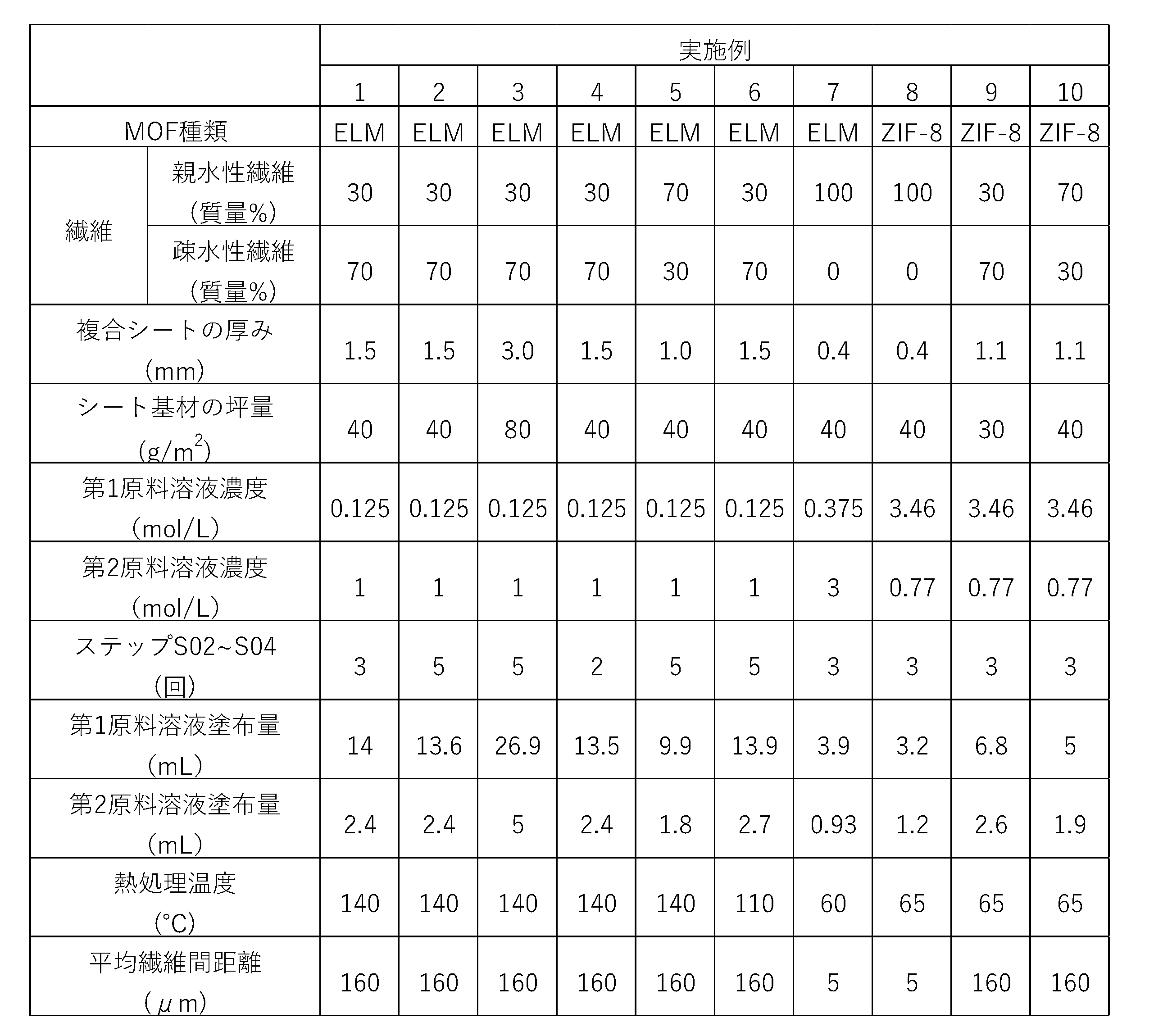

(比較例1~6)
次に、比較例1~6に係る複合シートのサンプルを表3に示す条件で作製した。また、各サンプルについて、実施例1~10と同様の分析及び評価を行った。表4には、各サンプルについての分析結果及び評価結果が示されている。以下、比較例1~6について詳細に説明する。比較例1~5では、実施例1~7と同様に、MOFとしてELM-11を用いた。比較例8では、実施例8~10と同様に、MOFとしてZIF-8を用いた。
次に、比較例1~6に係る複合シートのサンプルを表3に示す条件で作製した。また、各サンプルについて、実施例1~10と同様の分析及び評価を行った。表4には、各サンプルについての分析結果及び評価結果が示されている。以下、比較例1~6について詳細に説明する。比較例1~5では、実施例1~7と同様に、MOFとしてELM-11を用いた。比較例8では、実施例8~10と同様に、MOFとしてZIF-8を用いた。
・比較例1~3
比較例1~3では、シート基材として実施例1と同様の不織布を用いた。
比較例1,2では、上記実施形態に係るステップS02~S04の代わりに、シート基材にバインダ溶液(水溶性バインダ:ポリビニルアルコール(PVA)、固形分20%)を含浸させた。その後、予め生成されたMOFの粒子(平均粒径5μm)をシート基材の両面に、表4に示すMOFの含有比率になるように、散布した。そして、室温でプレスした後、100℃、2時間の熱処理を実施した。
比較例3では、上記実施形態に係るステップS02~S04の代わりに、予め生成されたMOFの塗料をシート基材の両面に塗工した後、100℃、2時間の熱処理を実施した。比較例3で用いたMOFの塗料の構成は以下のとおりである。
MOFの平均粒径:5μm
バインダ:水溶性PVA
MOF/バインダ比率:1/1
溶媒:脱イオン水
固形分/20%
比較例1~3ではいずれも、複合シート中の繊維はその形態を維持していた。
比較例1~3では、シート基材として実施例1と同様の不織布を用いた。
比較例1,2では、上記実施形態に係るステップS02~S04の代わりに、シート基材にバインダ溶液(水溶性バインダ:ポリビニルアルコール(PVA)、固形分20%)を含浸させた。その後、予め生成されたMOFの粒子(平均粒径5μm)をシート基材の両面に、表4に示すMOFの含有比率になるように、散布した。そして、室温でプレスした後、100℃、2時間の熱処理を実施した。
比較例3では、上記実施形態に係るステップS02~S04の代わりに、予め生成されたMOFの塗料をシート基材の両面に塗工した後、100℃、2時間の熱処理を実施した。比較例3で用いたMOFの塗料の構成は以下のとおりである。
MOFの平均粒径:5μm
バインダ:水溶性PVA
MOF/バインダ比率:1/1
溶媒:脱イオン水
固形分/20%
比較例1~3ではいずれも、複合シート中の繊維はその形態を維持していた。
比較例1~3に係る複合シートのサンプルではいずれも、MOFは繊維の表面に直接担持されていなかった。いずれのサンプルも芯鞘繊維の鞘部の溶解又はバインダの接触により、MOFの表面が部分的に被覆されていた。
・比較例4
比較例4では、シート基材としてバインダを用いてガラス繊維をシート状に固定した多孔質基板を用いた。また、上記の比較構成例に係る複合シートの製造プロセスと同様に、ステップS02において第1原料溶液を含浸させたシート基材を乾燥させた後にステップS03においてシート基材に第2原料溶液を含浸させた。ステップS02,S03の間におけるシート基材を乾燥させるステップを含めてステップS02~S04の回数を3回とした。比較例4では、複合シート中の繊維はその形態を維持していた。
比較例4では、シート基材としてバインダを用いてガラス繊維をシート状に固定した多孔質基板を用いた。また、上記の比較構成例に係る複合シートの製造プロセスと同様に、ステップS02において第1原料溶液を含浸させたシート基材を乾燥させた後にステップS03においてシート基材に第2原料溶液を含浸させた。ステップS02,S03の間におけるシート基材を乾燥させるステップを含めてステップS02~S04の回数を3回とした。比較例4では、複合シート中の繊維はその形態を維持していた。
・比較例5
比較例5では、シート基材としてPE繊維で構成された不織布を用いた。上記実施形態に係るステップS02~S04の代わりに、予め生成されたMOFの粒子(平均粒径5μm)をシート基材の両面に散布した。
得られたサンプルは熱処理により融点の低いPEのみで構成されたPE繊維が溶解して繊維としての形態を維持しておらず、ポリエチレン樹脂でMOFが被覆されたシートとなっていた。
比較例5では、シート基材としてPE繊維で構成された不織布を用いた。上記実施形態に係るステップS02~S04の代わりに、予め生成されたMOFの粒子(平均粒径5μm)をシート基材の両面に散布した。
得られたサンプルは熱処理により融点の低いPEのみで構成されたPE繊維が溶解して繊維としての形態を維持しておらず、ポリエチレン樹脂でMOFが被覆されたシートとなっていた。
・比較例6
比較例6に係るサンプルは、MOFの含有比率が80質量%未満である点で上記実施形態とは異なる。
比較例6に係るサンプルは、MOFの含有比率が80質量%未満である点で上記実施形態とは異なる。
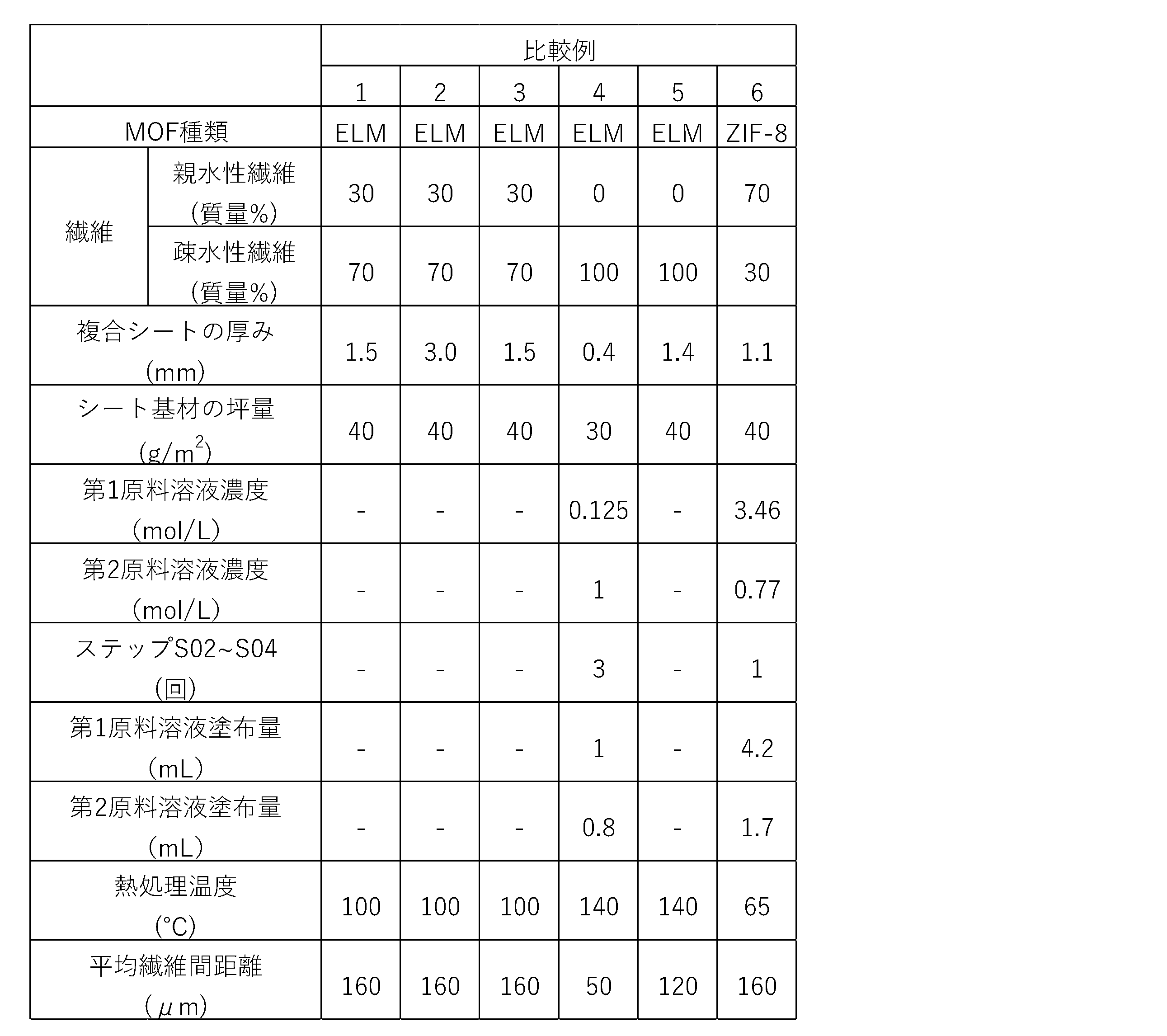

Claims (34)
- 繊維で構成されたシート基材中に金属有機構造体が分散された複合シートであって、
前記金属有機構造体が前記繊維の表面に担持され、
前記複合シート全体の質量に対する前記金属有機構造体の質量の比率が80質量%以上であり、
前記複合シートの厚み方向の中央部を構成する前記繊維における前記金属有機構造体による表面被覆率が60%以上100%以下であり、
前記金属有機構造体の表面露出率が50%以上である
複合シート。 - 前記繊維の少なくとも一部において長手方向と直交する断面における前記金属有機構造体による周方向被覆率が80%以上100%以下、好ましくは85%以上、より好ましくは90%以上である
請求項1に記載の複合シート。 - 振とう評価による前記金属有機構造体の脱落率が0質量%以上20質量%以下、好ましくは18質量%以下、より好ましくは15質量%以下、更に好ましくは9質量%以下である
請求項1又は2に記載の複合シート。 - 最大曲げ応力が0MPa以上5MPa以下、好ましくは3MPa以下、より好ましくは1MPa以下、更に好ましくは0.1MPa以下である
請求項1から3のいずれか1項に記載の複合シート。 - 前記繊維が有機繊維を含む
請求項1から4のいずれか1項に記載の複合シート。 - 前記繊維が親水性繊維及び疎水性繊維を含む
請求項1から5のいずれか1項に記載の複合シート。 - 前記親水性繊維がセルロース繊維を含み、前記疎水性繊維が合成繊維を含む
請求項6に記載の複合シート。 - 前記金属有機構造体の表面露出率が50%以上100%以下、好ましくは70%以上、より好ましくは90%以上である
請求項1から7のいずれか1項に記載の複合シート。 - 前記金属有機構造体との合計質量に対して、0質量%以上10質量%以下、好ましくは5質量%以下、より好ましくは1質量%以下のバインダを含む
請求項1から8のいずれか1項に記載の複合シート。 - 前記複合シート全体の質量に対して、0質量%以上10質量%以下、好ましくは5質量%以下、より好ましくは1質量%以下のバインダを含む
請求項1から9のいずれか1項に記載の複合シート。 - 前記複合シートがバインダを含まない
請求項1から9のいずれか1項に記載の複合シート。 - 前記金属有機構造体が前記繊維の表面に直接担持されている
請求項1から11のいずれか1項に記載の複合シート。 - 前記繊維の表面に前記金属有機構造体の層が形成されている
請求項1から12のいずれか1項に記載の複合シート。 - 前記複合シートの厚み方向の中央部を構成する前記繊維における前記金属有機構造体による表面被覆率が70%以上であり、好ましくは80%以上である
請求項1から13のいずれか1項に記載の複合シート。 - 前記金属有機構造体は、二酸化炭素を選択的に吸着可能に構成されている
請求項1から14のいずれか1項に記載の複合シート。 - 前記複合シートの厚みが0.2mm以上10mm以下、好ましくは0.5mm以上5mm以下、より好ましくは1mm以上である
請求項1から15のいずれか1項に記載の複合シート。 - 前記複合シートのガーレー通気度が0秒/100mL以上10秒/100mL以下、好ましくは5秒/100mL以下、より好ましくは0.5秒/100mL以下である
請求項1から16のいずれか1項に記載の複合シート。 - 前記シート基材が不織布である
請求項1から17のいずれか1項に記載の複合シート。 - 前記金属有機構造体の含有比率が、前記複合シート全体の質量に対して、80質量%以上99質量%以下、好ましくは85質量%以上である
請求項1から18のいずれか1項に記載の複合シート。 - 前記繊維の繊維としての形態が維持されている
請求項1から19のいずれか1項に記載の複合シート。 - 前記複合シートにおける前記シート基材の繊維間距離は1μm以上1000μm以下、好ましくは10μm以上500μm以下、より好ましくは50μm以上400μm以下、更に好ましくは100μm以上300μm以下である
請求項1から20のいずれか1項に記載の複合シート。 - 繊維で構成されたシート基材中に金属有機構造体が担持された複合シートの製造方法であって、
前記金属有機構造体の原料となる金属イオン及び有機配位子のうち、一方を含む第1原料溶液と、他方を含む第2原料溶液と、を用意し、
前記第1原料溶液を前記シート基材に含浸させ、
前記シート基材に含浸させた前記第1原料溶液が乾燥しないうちに前記第2原料溶液を前記シート基材に含浸させ、
前記第2原料溶液を含浸させた前記シート基材を乾燥させ、
前記第2原料溶液を含浸させた前記シート基材に熱処理を加え、
前記熱処理の後において前記複合シート全体の質量に対する前記金属有機構造体の質量の比率が80質量%以上となるように、前記熱処理の前における、
前記第1原料溶液を前記シート基材に含浸させ、
前記シート基材に含浸させた前記第1原料溶液が乾燥しないうちに前記第2原料溶液を前記シート基材に含浸させ、
前記第2原料溶液を含浸させた前記シート基材を乾燥させる
工程を繰り返す
複合シートの製造方法。 - 前記第1原料溶液及び前記第2原料溶液のうち、一方が30質量%以上99質量%以下の水を含み、他方が30質量%以上99質量%以下の有機溶媒を含む
請求項22に記載の複合シートの製造方法。 - 前記繊維が有機繊維を含む
請求項22又は23に記載の複合シートの製造方法。 - 前記繊維が親水性繊維及び疎水性繊維を含む
請求項22から24のいずれか1項に記載の複合シートの製造方法。 - 前記第1原料溶液が前記金属イオンを含み、前記第2原料溶液が前記有機配位子を含む
請求項22から25のいずれか1項に記載の複合シートの製造方法。 - 前記第1原料溶液の溶媒が水を含み、前記第2原料溶液の溶媒が有機溶媒を含む
請求項26に記載の複合シートの製造方法。 - 前記熱処理の前における、
前記第1原料溶液を前記シート基材に含浸させ、
前記シート基材に含浸させた前記第1原料溶液が乾燥しないうちに前記第2原料溶液を前記シート基材に含浸させ、
前記第2原料溶液を含浸させた前記シート基材を乾燥させる
工程の合計回数が2回以上20回以下、好ましくは2回以上15回以下、より好ましくは3回以上10回以下である
請求項22から27のいずれか1項に記載の複合シートの製造方法。 - 前記熱処理によって前記金属有機構造体を脱水和する
請求項22から28のいずれか1項に記載の複合シートの製造方法。 - 前記繊維が芯鞘繊維を含み、
前記芯鞘繊維では、芯部分の融点が前記熱処理の温度よりも高く、鞘部分の融点が前記乾燥の温度より高く、かつ前記熱処理の温度よりも低い
請求項22から29のいずれか1項に記載の複合シートの製造方法。 - 前記第1原料溶液を前記シート基材に含浸させる時間が0.1分以上30分以下である
請求項22から30のいずれか1項に記載の複合シートの製造方法。 - 前記第2原料溶液を前記シート基材に含浸させる時間が0.1分以上30分以下である
請求項22から31のいずれか1項に記載の複合シートの製造方法。 - スポイトによる滴下、霧吹き、スプレーコート、ダイコート及びカーテンコートから選ばれる1又は2以上によって、前記第1原料溶液及び前記第2原料溶液の少なくとも一方を前記シート基材に含浸させる
請求項22から32のいずれか1項に記載の複合シートの製造方法。 - 第1原料溶液における金属イオンの濃度及び第2原料溶液における有機配位子の濃度がいずれも0.05mol/L以上10mol/L以下である
請求項26又は27に記載の複合シートの製造方法。
Priority Applications (3)
| Application Number | Priority Date | Filing Date | Title |
|---|---|---|---|
| CN202480003735.1A CN119895094A (zh) | 2023-07-12 | 2024-06-24 | 复合片 |
| EP24837277.3A EP4745296A1 (en) | 2023-07-12 | 2024-06-24 | COMPOSITE SHEET |
| US19/206,430 US20250269624A1 (en) | 2023-07-12 | 2025-05-13 | Composite sheet |
Applications Claiming Priority (4)
| Application Number | Priority Date | Filing Date | Title |
|---|---|---|---|
| JP2023114210 | 2023-07-12 | ||
| JP2023-114210 | 2023-07-12 | ||
| JP2024100986A JP7608665B1 (ja) | 2023-07-12 | 2024-06-24 | 複合シート |
| JP2024-100986 | 2024-06-24 |
Related Child Applications (1)
| Application Number | Title | Priority Date | Filing Date |
|---|---|---|---|
| US19/206,430 Continuation US20250269624A1 (en) | 2023-07-12 | 2025-05-13 | Composite sheet |
Publications (1)
| Publication Number | Publication Date |
|---|---|
| WO2025013602A1 true WO2025013602A1 (ja) | 2025-01-16 |
Family
ID=94127788
Family Applications (1)
| Application Number | Title | Priority Date | Filing Date |
|---|---|---|---|
| PCT/JP2024/022786 Ceased WO2025013602A1 (ja) | 2023-07-12 | 2024-06-24 | 複合シート |
Country Status (5)
| Country | Link |
|---|---|
| US (1) | US20250269624A1 (ja) |
| EP (1) | EP4745296A1 (ja) |
| JP (1) | JP7608665B1 (ja) |
| CN (1) | CN119895094A (ja) |
| WO (1) | WO2025013602A1 (ja) |
Families Citing this family (1)
| Publication number | Priority date | Publication date | Assignee | Title |
|---|---|---|---|---|
| CN119932810B (zh) * | 2025-03-04 | 2025-12-09 | 中国矿业大学 | 一种紫外屏蔽自清洁聚乳酸纤维冷却膜及其制备方法 |
Citations (12)
| Publication number | Priority date | Publication date | Assignee | Title |
|---|---|---|---|---|
| JPH08503272A (ja) * | 1992-11-18 | 1996-04-09 | ヘキスト・セラニーズ・コーポレーション | 固定された粒子物質を含有する繊維状構造物およびその製造方法 |
| JP2005034693A (ja) * | 2003-07-16 | 2005-02-10 | Toray Ind Inc | エアフィルタ用濾材およびその製造方法 |
| US20120141685A1 (en) * | 2010-12-07 | 2012-06-07 | Basf Se | Process For Coating A Support Surface With A Porous Metal-Organic Framework |
| JP5150617B2 (ja) * | 2006-04-18 | 2013-02-20 | ビーエーエスエフ ソシエタス・ヨーロピア | フマル酸アルミニウムから成る有機金属フレームワーク材料の使用方法 |
| JP2016193957A (ja) * | 2015-03-31 | 2016-11-17 | 東ソー株式会社 | 多孔性配位高分子 |
| JP2019018175A (ja) * | 2017-07-20 | 2019-02-07 | 住友ベークライト株式会社 | 複合体、複合体の製造方法、吸着材、および液体の清浄化方法 |
| CN109881483A (zh) | 2019-01-24 | 2019-06-14 | 浙江理工大学 | 一种利用金属-有机框架材料功能化改性聚丙烯/纤维素水刺无纺布的方法及其应用 |
| CN112002938A (zh) | 2020-08-28 | 2020-11-27 | 南京大学 | 基于Cu(BDC)MOF多级结构的复合固态电解质膜及其制备方法 |
| US20210189620A1 (en) * | 2019-11-15 | 2021-06-24 | North Carolina State University | Fibers with absorbent particles adhered thereto, methods for their production and articles thereof |
| WO2021153626A1 (ja) * | 2020-01-31 | 2021-08-05 | 東洋紡株式会社 | 吸着シート、吸着エレメント、およびそれを用いた吸着処理装置 |
| JP2021191913A (ja) | 2020-01-28 | 2021-12-16 | 旭化成株式会社 | セルロースと金属有機構造体との複合体、及びその製造方法 |
| JP2023044403A (ja) * | 2021-09-17 | 2023-03-30 | ダイキン工業株式会社 | 吸着素子、調湿装置および大気造水機 |
-
2024
- 2024-06-24 EP EP24837277.3A patent/EP4745296A1/en active Pending
- 2024-06-24 WO PCT/JP2024/022786 patent/WO2025013602A1/ja not_active Ceased
- 2024-06-24 CN CN202480003735.1A patent/CN119895094A/zh active Pending
- 2024-06-24 JP JP2024100986A patent/JP7608665B1/ja active Active
-
2025
- 2025-05-13 US US19/206,430 patent/US20250269624A1/en active Pending
Patent Citations (12)
| Publication number | Priority date | Publication date | Assignee | Title |
|---|---|---|---|---|
| JPH08503272A (ja) * | 1992-11-18 | 1996-04-09 | ヘキスト・セラニーズ・コーポレーション | 固定された粒子物質を含有する繊維状構造物およびその製造方法 |
| JP2005034693A (ja) * | 2003-07-16 | 2005-02-10 | Toray Ind Inc | エアフィルタ用濾材およびその製造方法 |
| JP5150617B2 (ja) * | 2006-04-18 | 2013-02-20 | ビーエーエスエフ ソシエタス・ヨーロピア | フマル酸アルミニウムから成る有機金属フレームワーク材料の使用方法 |
| US20120141685A1 (en) * | 2010-12-07 | 2012-06-07 | Basf Se | Process For Coating A Support Surface With A Porous Metal-Organic Framework |
| JP2016193957A (ja) * | 2015-03-31 | 2016-11-17 | 東ソー株式会社 | 多孔性配位高分子 |
| JP2019018175A (ja) * | 2017-07-20 | 2019-02-07 | 住友ベークライト株式会社 | 複合体、複合体の製造方法、吸着材、および液体の清浄化方法 |
| CN109881483A (zh) | 2019-01-24 | 2019-06-14 | 浙江理工大学 | 一种利用金属-有机框架材料功能化改性聚丙烯/纤维素水刺无纺布的方法及其应用 |
| US20210189620A1 (en) * | 2019-11-15 | 2021-06-24 | North Carolina State University | Fibers with absorbent particles adhered thereto, methods for their production and articles thereof |
| JP2021191913A (ja) | 2020-01-28 | 2021-12-16 | 旭化成株式会社 | セルロースと金属有機構造体との複合体、及びその製造方法 |
| WO2021153626A1 (ja) * | 2020-01-31 | 2021-08-05 | 東洋紡株式会社 | 吸着シート、吸着エレメント、およびそれを用いた吸着処理装置 |
| CN112002938A (zh) | 2020-08-28 | 2020-11-27 | 南京大学 | 基于Cu(BDC)MOF多级结构的复合固态电解质膜及其制备方法 |
| JP2023044403A (ja) * | 2021-09-17 | 2023-03-30 | ダイキン工業株式会社 | 吸着素子、調湿装置および大気造水機 |
Also Published As
| Publication number | Publication date |
|---|---|
| JP2025013207A (ja) | 2025-01-24 |
| US20250269624A1 (en) | 2025-08-28 |
| CN119895094A (zh) | 2025-04-25 |
| JP7608665B1 (ja) | 2025-01-06 |
| EP4745296A1 (en) | 2026-05-20 |
Similar Documents
| Publication | Publication Date | Title |
|---|---|---|
| Liu et al. | Thin film nanocomposite reverse osmosis membrane incorporated with UiO-66 nanoparticles for enhanced boron removal | |
| Chen et al. | Fabrication of Cellulosic Paper Containing Zeolitic Imidazolate Framework and Its Application in Removal of Anionic Dye from Aqueous Solution. | |
| US20190217517A1 (en) | Polymer composites for fused filament fabrication and methods of making the same | |
| US20250325962A1 (en) | Hydrophobic and Porous Sorbent Polymer Composites and Methods for CO2 Capture | |
| TWI789408B (zh) | 流體分離用碳膜及其製造方法 | |
| JP7608665B1 (ja) | 複合シート | |
| WO2009122975A1 (ja) | 脱臭性繊維構造物およびエアフィルター | |
| CN110777537B (zh) | 一种zif-8/无纺布复合材料及其制备方法 | |
| JP4791049B2 (ja) | エアフィルタ用シート及びその製造方法並びにエアフィルタ | |
| JP2021529079A (ja) | 選択透過性酸化グラフェン要素 | |
| JP2023147220A (ja) | 金属有機フレームワーク、金属有機フレームワークを含む組成物、該組成物からなる膜及びガス分離膜、金属有機フレームワークの製造方法並びに二酸化炭素吸着材 | |
| JP7284001B2 (ja) | アルカリ水電解用隔膜ならびに該隔膜の製造方法 | |
| US12292210B2 (en) | Dehumidifying member, dehumidifying rotor, and manufacturing method of dehumidifying member | |
| JP7608664B1 (ja) | 複合シート | |
| WO2018160385A1 (en) | Hydrogen sulfide filters, methods of forming the hydrogen sulfide filters, and systems including such filters | |
| Byun et al. | Electrospun nanofiber-supported thin-film composite membrane by introducing graphene oxide interlayer for water vapor/N2 separation | |
| US20250154700A1 (en) | Porous non-woven ptfe compositions and methods of forming | |
| JP6243481B2 (ja) | 水分離複合膜 | |
| Kuzminova et al. | Sustainable pervaporation membranes based on carboxymethyl cellulose modified with metal organic frameworks for water/isopropanol separation | |
| JP6806809B2 (ja) | 気体分離膜 | |
| TW202424079A (zh) | 複合多孔質體、及複合多孔質體之製造方法 | |
| Song et al. | In situ reconstruction of ZIF-8 loaded on fibrous supports | |
| JP5835914B2 (ja) | 吸水材料組成物および吸水性シート | |
| Gholamzadeh Moghadam et al. | Optimizing dual-layer composite membranes with functionalized CNT loadings using response surface methodology | |
| JP7516174B2 (ja) | ガス分離膜及びその製造方法 |
Legal Events
| Date | Code | Title | Description |
|---|---|---|---|
| WWE | Wipo information: entry into national phase |
Ref document number: 202480003735.1 Country of ref document: CN |
|
| 121 | Ep: the epo has been informed by wipo that ep was designated in this application |
Ref document number: 24837277 Country of ref document: EP Kind code of ref document: A1 |
|
| WWP | Wipo information: published in national office |
Ref document number: 202480003735.1 Country of ref document: CN |
|
| NENP | Non-entry into the national phase |
Ref country code: DE |