WO2025013585A1 - 湿分分離加熱器モジュール及び湿分分離加熱器を設置する方法 - Google Patents
湿分分離加熱器モジュール及び湿分分離加熱器を設置する方法 Download PDFInfo
- Publication number
- WO2025013585A1 WO2025013585A1 PCT/JP2024/022720 JP2024022720W WO2025013585A1 WO 2025013585 A1 WO2025013585 A1 WO 2025013585A1 JP 2024022720 W JP2024022720 W JP 2024022720W WO 2025013585 A1 WO2025013585 A1 WO 2025013585A1
- Authority
- WO
- WIPO (PCT)
- Prior art keywords
- moisture separator
- separator heater
- moisture
- frame
- heater
- Prior art date
- Legal status (The legal status is an assumption and is not a legal conclusion. Google has not performed a legal analysis and makes no representation as to the accuracy of the status listed.)
- Ceased
Links
Images


Classifications
-
- F—MECHANICAL ENGINEERING; LIGHTING; HEATING; WEAPONS; BLASTING
- F22—STEAM GENERATION
- F22B—METHODS OF STEAM GENERATION; STEAM BOILERS
- F22B37/00—Component parts or details of steam boilers
- F22B37/02—Component parts or details of steam boilers applicable to more than one kind or type of steam boiler
- F22B37/26—Steam-separating arrangements
- F22B37/268—Steam-separating arrangements specially adapted for steam generators of nuclear power plants
-
- E—FIXED CONSTRUCTIONS
- E04—BUILDING
- E04H—BUILDINGS OR LIKE STRUCTURES FOR PARTICULAR PURPOSES; SWIMMING OR SPLASH BATHS OR POOLS; MASTS; FENCING; TENTS OR CANOPIES, IN GENERAL
- E04H9/00—Buildings, groups of buildings or shelters adapted to withstand or provide protection against abnormal external influences, e.g. war-like action, earthquake or extreme climate
- E04H9/02—Buildings, groups of buildings or shelters adapted to withstand or provide protection against abnormal external influences, e.g. war-like action, earthquake or extreme climate withstanding earthquake or sinking of ground
-
- F—MECHANICAL ENGINEERING; LIGHTING; HEATING; WEAPONS; BLASTING
- F22—STEAM GENERATION
- F22B—METHODS OF STEAM GENERATION; STEAM BOILERS
- F22B37/00—Component parts or details of steam boilers
- F22B37/02—Component parts or details of steam boilers applicable to more than one kind or type of steam boiler
- F22B37/26—Steam-separating arrangements
-
- F—MECHANICAL ENGINEERING; LIGHTING; HEATING; WEAPONS; BLASTING
- F22—STEAM GENERATION
- F22G—SUPERHEATING OF STEAM
- F22G3/00—Steam superheaters characterised by constructional features; Details or component parts thereof
Definitions
- a moisture separator heater removes moisture from the wet steam discharged from the high-pressure turbine, and the saturated steam from which moisture has been removed is reheated with main steam and extracted steam from the high-pressure turbine, and is supplied to the low-pressure turbine as high-temperature steam. This improves the thermal efficiency of the entire plant and suppresses erosion of the low-pressure turbine.
- the moisture separator heater is installed on top of the beams of the building, for example, on the operation floor of the turbine building or on the floor below it.
- At least one embodiment of the present disclosure aims to provide a moisture separator heater module and a method for installing a moisture separator heater that facilitates installation of the moisture separator heater.
- the moisture separator heater module of the present disclosure is a moisture separator heater module comprising a moisture separator heater including a cylindrical body extending along a longitudinal axis, and an installation structure supporting the moisture separator heater, the installation structure comprising a frame and a support mechanism fixed to the upper part of the frame and having a hanging member, the hanging member suspending and supporting the moisture separator heater at at least two different positions in a direction along the longitudinal axis such that the longitudinal axis extends along the horizontal direction.
- the moisture separator heater module is preassembled and then transported to the installation site and installed, or the moisture separator heater module is assembled at the installation site, allowing the moisture separator heater to be installed at the installation site, making it easy to install the moisture separator heater.
- FIG. 1 is a schematic diagram of a power plant including a moisture separator heater module according to an embodiment of the present disclosure.
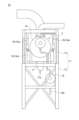
- FIG. 2 is a schematic diagram of a moisture separator heater module according to an embodiment of the present disclosure. 2 is a diagram showing the angle that the longitudinal axis L of the body of a moisture separator heater in an embodiment of the moisture separator heater module according to the present disclosure makes with respect to the horizontal direction.
- FIG. FIG. 2 is a schematic diagram of a moisture separator heater module according to an embodiment of the present disclosure.
- the power plant 1 is provided with a high-pressure turbine 2, a low-pressure turbine 3, a moisture separator heater 4 that removes moisture from the wet steam discharged from the high-pressure turbine 2 and reheats the saturated steam from which the moisture has been removed, a steam generating device 5 (which is not limited to a steam generator, for example) that generates steam used in the high-pressure turbine 2 and the moisture separator heater 4, and a condenser 7 that condenses the steam discharged from the low-pressure turbine 3.
- a steam generating device 5 which is not limited to a steam generator, for example
- the moisture separator heater 4 includes a moisture separator section 4a that removes moisture from the moist steam, and a reheat section 4b that reheats the saturated steam from which moisture has been removed in the moisture separator section 4a.
- the moisture separator heater 4 is installed as a moisture separator heater module 10 supported by an installation structure 11. That is, the moisture separator heater module 10 includes the moisture separator heater 4 and an installation structure 11 that supports the moisture separator heater 4.
- the installation structure 11 includes a frame 12 that is placed at the installation location, and a support mechanism 13 fixed to the upper part of the frame 12.
- the frame 12 and the support mechanism 13 may each be constructed by assembling multiple L-shaped steel members.
- the frame 12 is placed on the floor of the installation location, it is possible that the floor area on which the moisture separator heater module 10 is placed may be small depending on the installation location.
- the frame 12 is constructed by assembling elongated members such as L-shaped steel members, and the frame 12 is placed on the floor by abutting the lower ends of multiple elongated members extending vertically against the floor. It is preferable that no wall-like members are provided in the areas other than the elongated members, and that there is nothing in the areas other than the elongated members, i.e., that the areas are openings. With this configuration, the inside of the frame 12 and the support mechanism 13 can be seen through the openings formed by the elongated members, and the inside can be accessed from the outside through the openings.
- the elongated members are not limited to L-shaped steel members, and may be rod-shaped members with any cross-sectional shape in the longitudinal direction.
- the moisture separator heater 4 includes a cylindrical body 4c that extends along a longitudinal axis L.
- the moisture separator section 4a (see FIG. 1) and the reheat section 4b (see FIG. 1) described above are housed inside the body 4c.
- the moisture separator heater 4 is supported by a support mechanism 13 so that the longitudinal axis L extends along the horizontal direction. Note that "the longitudinal axis L extends along the horizontal direction” does not only mean that the longitudinal axis L faces completely horizontally, but as shown in FIG. 3, the longitudinal axis L may form a certain angle ⁇ with respect to the horizontal direction.
- this angle ⁇ is as small as possible, but this angle ⁇ is less than 90°, that is, it is sufficient that the longitudinal axis L does not face the vertical direction, and is preferably 60° or less, more preferably 45° or less, even more preferably 30° or less, and most preferably 10° or less.
- the support mechanism 13 includes a hanging member 14 that suspends and supports the moisture separator heater 4.
- the hanging member 14 includes a first member 14a and a second member 14b that suspend and support the moisture separator heater 4 at two different positions in the direction along the longitudinal axis L.
- the first member 14a and the second member 14b each include a support member 15 that supports the body 4c of the moisture separator heater 4 from below, and two hanging members 16, 16, one end of which is fixed to the support mechanism 13 and the other end of which is fixed to the support member 15.
- the configuration of the support member 15 is not particularly limited, and may be, for example, a band-like member or a plate-like member having a recess formed in the upper edge portion corresponding to the outer peripheral shape of the body 4c. In FIG.
- the hanging member 14 is composed of two members, the first member 14a and the second member 14b, but it is not limited to two, and may be composed of three or more members as long as at least two positions in the direction along the longitudinal axis are different.
- the moisture separator heater 4 can be suspended and supported with the longitudinal axis L inclined relative to the horizontal direction (0° ⁇ 90°).
- the moisture separation heater 4 is equipped with a moisture separation drain tank 17 that stores moisture drain mechanically separated from the wet steam in the moisture separation section 4a (see Figure 1) inside the body 4c.
- the installation location of the moisture separation drain tank 17 is not particularly limited, but the moisture separation drain tank 17 may be installed so as to be fixed to the body 4c.
- the moisture separation drain tank 17 is fixed to the body 4c, although this is not limited, it is preferable that the moisture separation drain tank 17 is fixed to the body 4c at the lowest position of the body 4c in the vertical direction. This allows the moisture drain to be efficiently collected in the moisture separation drain tank 17.
- the moisture separation drain tank 17 fixed to the body 4c of the moisture separation heater 4 is at a certain height from the floor surface of the location where the moisture separation heater module 10 is installed.
- the moisture drain in the moisture separation drain tank 17 can be pumped through the pipe 17a by the hydraulic head pressure, so it is possible to avoid providing a drain pump for pumping the moisture drain in the moisture separation drain tank 17 to the pipe 17a.
- the moisture separator heater 4 is provided with a moisture separator heater drain tank 18 as another related device in the reheat section 4b (see FIG. 1) in the body 4c, which stores drainage formed by condensing the heated steam that has exchanged heat with the saturated steam after moisture has been removed.
- the installation location of the moisture separator heater drain tank 18 is not particularly limited, but the moisture separator heater drain tank 18 may be provided in the installation structure 11, preferably in the frame 12. With this configuration, the moisture separator heater drain tank 18 is also provided in the moisture separator heater module 10, making it easier to install not only the moisture separator heater 4 but also its related devices.
- the drainage in the moisture separator heater drain tank 18 can be sent from the moisture separator heater drain tank 18 to any location via the piping 18a.
- the moisture separator heater 4 may have an inlet 4d at one end 4c1 in the direction along the longitudinal axis L for the moist steam to flow into the moisture separator heater 4.
- the pipe 19 through which the moist steam flowing into the moisture separator heater 4 flows can be prevented from being located below the moisture separator heater 4, so that the frame 12 of the installation structure 11 can be designed compactly.
- the inlet 4d may be provided at the lowest or highest position of the body 4c in the vertical direction, although such an effect cannot be obtained.
- the moisture separator heater 4 Since the moisture separator heater 4 is suspended by the support mechanism 13, there is a possibility that the moisture separator heater 4 will shake in the event of an earthquake, causing the hanging member 16 to break and the moisture separator heater 4 to fall. For this reason, in countries with frequent earthquakes such as Japan, it is preferable to provide a damper to suppress the shaking of the moisture separator heater 4.
- the moisture separator heater module 10 is assembled at a location different from the location where the moisture separator heater 4 is to be installed. If the moisture separator heater drain tank 18 is provided on the installation structure 11, the moisture separator heater drain tank 18 is provided on the installation structure 11 when assembling the moisture separator heater module 10. Next, the moisture separator heater module 10 is placed at the installation location using a crane or the like, and the piping of the power plant 1 is connected to the moisture separator heater 4, thereby installing the moisture separator heater 4.
- part of the installation structure 11, i.e., the frame 12 is assembled at the installation site. If the frame 12 is to be provided with a moisture separator heater drain tank 18, the frame 12 is assembled and then the moisture separator heater drain tank 18 is provided on the frame 12. Next, at a location different from where the moisture separator heater 4 is to be installed, a support mechanism 13 is prepared with the moisture separator heater 4 suspended and supported, and a crane or the like is used to place the support mechanism 13 with the moisture separator heater 4 suspended and supported on top of the frame 12, and the support mechanism 13 is fixed to the frame 12. As a result, the moisture separator heater module 10 is constructed at the installation site, and the moisture separator heater 4 is installed at the installation site.
- the moisture separator heater module 10 is preassembled and then the moisture separator heater module 10 is transported to the installation site and installed, or the moisture separator heater module 10 is assembled at the installation site, so that the moisture separator heater 4 can be installed at the installation site, making it easy to install the moisture separator heater 4.
- a moisture separator heater module comprises: A moisture separator heater (4) including a cylindrical body (4c) extending along a longitudinal axis (L); A moisture separator heater module (10) comprising: The installation structure (11) is A frame (12); a support mechanism (13) fixed to an upper portion of the frame (12) and having a hanging member (14); The suspension member (14) suspends and supports the moisture separator/heater (4) at least at two different positions in a direction along the longitudinal axis (L) so that the longitudinal axis (L) extends horizontally.
- the moisture separator heater module is preassembled and then transported to the installation site and installed, or the moisture separator heater module is assembled at the installation site, allowing the moisture separator heater to be installed at the installation site, making it easy to install the moisture separator heater.
- a moisture separator/heater module is the moisture separator/heater module of [1],
- the moisture separator heater (4) has an inlet (4d) at one end (4c1) in the direction along the longitudinal axis (L) for allowing wet steam to flow into the moisture separator heater (4).
- the piping through which the wet steam flows into the moisture separator heater does not need to be located below the moisture separator heater, allowing the frame of the installation structure to be designed compactly.
- a moisture separator/heater module is a moisture separator/heater module according to [1] or [2],
- a moisture separation drain tank (17) for storing moisture drain mechanically separated from the wet steam inside the body (4c) is fixed to the body (4c).
- the moisture separation heater is supported by being suspended from a support mechanism fixed to the top of the frame, so the moisture separation drain tank fixed to the body of the moisture separation heater is at a certain height from the floor surface of the location where the moisture separation heater module is installed.
- the moisture drain in the moisture separation drain tank can be pumped by head pressure, so it is not necessary to provide a drain pump for pumping the moisture drain in the moisture separation drain tank.
- a moisture separator/heater module is a moisture separator/heater module according to any one of [1] to [3],
- a moisture separator heater drain tank (18) for storing drain generated by condensation of heating steam in the body (4c) is fixed to the frame (12).
- the moisture separator heater drain tank is also provided in the moisture separator heater module, making it easier to install not only the moisture separator heater but also its associated devices.
- a method for installing a moisture separator heater includes the steps of: A method for manufacturing a moisture separator heater module (10) according to any one of [1] to [4], and installing said moisture separator heater module (10).
- the moisture separator heater module is preassembled and then transported and installed at the installation location, allowing the moisture separator heater to be installed at the installation location, making it easier to install the moisture separator heater.
- a method for installing a moisture separator heater includes the steps of: Installing the frame (12); and a step of fixing the support mechanism (13) that suspends and supports the moisture separator heater (4) onto the frame (12), thereby forming any one of the moisture separator heater modules (10) [1] to [4].
- the moisture separator heater module can be assembled at the installation site, allowing the moisture separator heater to be installed at the installation site, making it easier to install the moisture separator heater.
- a method for installing a moisture separator heater includes the steps of: Installing the frame (12); Fixing the moisture separator heater drain tank (18) to the frame (12); The moisture separator heater drain tank (18) is fixed to the frame (12), and then the support mechanism (13) that suspends and supports the moisture separator heater (4) is fixed to the frame (12), thereby forming the moisture separator heater module (10) [4].
- the method of installing a moisture separator heater disclosed herein makes it easier to install not only the moisture separator heater but also its associated devices.
- Moisture separation heater 4c Body 4c1 (One end of body) 4d Inlet 10 Moisture separation heater module 11 Installation structure 12 Frame 13 Support mechanism 14 Suspension member 17 Moisture separation drain tank 18 Moisture separation heater drain tank L Longitudinal axis
Landscapes
- Engineering & Computer Science (AREA)
- Architecture (AREA)
- Mechanical Engineering (AREA)
- Environmental & Geological Engineering (AREA)
- Emergency Management (AREA)
- Business, Economics & Management (AREA)
- General Engineering & Computer Science (AREA)
- Physics & Mathematics (AREA)
- Civil Engineering (AREA)
- Structural Engineering (AREA)
- Thermal Sciences (AREA)
- High Energy & Nuclear Physics (AREA)
- Drying Of Solid Materials (AREA)
Priority Applications (3)
| Application Number | Priority Date | Filing Date | Title |
|---|---|---|---|
| CN202480037310.2A CN121336071A (zh) | 2023-07-07 | 2024-06-24 | 湿分分离加热器模块及湿分分离加热器的设置方法 |
| JP2025532645A JPWO2025013585A1 (https=) | 2023-07-07 | 2024-06-24 | |
| KR1020257042080A KR20260013206A (ko) | 2023-07-07 | 2024-06-24 | 습분 분리 가열기 모듈 및 습분 분리 가열기를 설치하는 방법 |
Applications Claiming Priority (2)
| Application Number | Priority Date | Filing Date | Title |
|---|---|---|---|
| JP2023112498 | 2023-07-07 | ||
| JP2023-112498 | 2023-07-07 |
Publications (1)
| Publication Number | Publication Date |
|---|---|
| WO2025013585A1 true WO2025013585A1 (ja) | 2025-01-16 |
Family
ID=94215167
Family Applications (1)
| Application Number | Title | Priority Date | Filing Date |
|---|---|---|---|
| PCT/JP2024/022720 Ceased WO2025013585A1 (ja) | 2023-07-07 | 2024-06-24 | 湿分分離加熱器モジュール及び湿分分離加熱器を設置する方法 |
Country Status (4)
| Country | Link |
|---|---|
| JP (1) | JPWO2025013585A1 (https=) |
| KR (1) | KR20260013206A (https=) |
| CN (1) | CN121336071A (https=) |
| WO (1) | WO2025013585A1 (https=) |
Citations (5)
| Publication number | Priority date | Publication date | Assignee | Title |
|---|---|---|---|---|
| JPS6093201A (ja) * | 1983-10-28 | 1985-05-25 | 株式会社日立製作所 | 湿分分離器 |
| JPS61230087A (ja) * | 1985-04-04 | 1986-10-14 | 株式会社東芝 | タ−ビン建屋 |
| JPS61266777A (ja) * | 1985-05-20 | 1986-11-26 | 株式会社日立製作所 | タ−ビン建屋 |
| JPH0539903A (ja) * | 1991-08-02 | 1993-02-19 | Toshiba Corp | 湿分分離加熱器 |
| JP2008128120A (ja) * | 2006-11-21 | 2008-06-05 | Mitsubishi Heavy Ind Ltd | 湿分分離器 |
Family Cites Families (1)
| Publication number | Priority date | Publication date | Assignee | Title |
|---|---|---|---|---|
| JP2007139460A (ja) | 2005-11-15 | 2007-06-07 | Toshiba Corp | 湿分分離加熱器室施工方法及び湿分分離加熱器室天井モジュール |
-
2024
- 2024-06-24 CN CN202480037310.2A patent/CN121336071A/zh active Pending
- 2024-06-24 JP JP2025532645A patent/JPWO2025013585A1/ja active Pending
- 2024-06-24 WO PCT/JP2024/022720 patent/WO2025013585A1/ja not_active Ceased
- 2024-06-24 KR KR1020257042080A patent/KR20260013206A/ko active Pending
Patent Citations (5)
| Publication number | Priority date | Publication date | Assignee | Title |
|---|---|---|---|---|
| JPS6093201A (ja) * | 1983-10-28 | 1985-05-25 | 株式会社日立製作所 | 湿分分離器 |
| JPS61230087A (ja) * | 1985-04-04 | 1986-10-14 | 株式会社東芝 | タ−ビン建屋 |
| JPS61266777A (ja) * | 1985-05-20 | 1986-11-26 | 株式会社日立製作所 | タ−ビン建屋 |
| JPH0539903A (ja) * | 1991-08-02 | 1993-02-19 | Toshiba Corp | 湿分分離加熱器 |
| JP2008128120A (ja) * | 2006-11-21 | 2008-06-05 | Mitsubishi Heavy Ind Ltd | 湿分分離器 |
Also Published As
| Publication number | Publication date |
|---|---|
| JPWO2025013585A1 (https=) | 2025-01-16 |
| KR20260013206A (ko) | 2026-01-27 |
| CN121336071A (zh) | 2026-01-13 |
Similar Documents
| Publication | Publication Date | Title |
|---|---|---|
| KR102425823B1 (ko) | 공랭식 응축기 시스템 | |
| CN101868676B (zh) | 可由销售店组装的太阳能吸收器热交换器 | |
| US7275503B2 (en) | Heat transfer tube panel module and method of constructing exhaust heat recovery boiler using the module | |
| CN101592334B (zh) | 用于装配蒸汽发生器的方法 | |
| ES2234719T3 (es) | Generador de vapor y procedimiento de montaje para el mismo. | |
| MXPA06001061A (es) | Modulo de panel con tubos intercambiadores de calor, y metodo para construir una caldera para recuperacion de calor de escape utilizando el modulo. | |
| CN101303121B (zh) | 锅炉装置、支撑结构及支撑锅炉装置蒸汽锅炉壁的方法 | |
| WO2025013585A1 (ja) | 湿分分離加熱器モジュール及び湿分分離加熱器を設置する方法 | |
| FI126039B (en) | Swivel bed boiler with a support structure for a particle separator | |
| KR102019476B1 (ko) | 모듈식 열 회수 증기 발생기 구성 | |
| KR101343427B1 (ko) | 화력 발전 플랜트 | |
| CN101627258A (zh) | 用于支撑动力锅炉壁的方法和装置 | |
| CN107208496B (zh) | 冷凝器 | |
| JP3970619B2 (ja) | 排熱回収ボイラの建設方法 | |
| JP7266586B2 (ja) | ボイラ構造体 | |
| US3345819A (en) | Foundation structure for turboelectric power plants | |
| CN100520170C (zh) | 用于大型蒸汽发生器的快速装配方法 | |
| JP3809565B2 (ja) | ボイラ天井面の水切り装置 | |
| JP3754309B2 (ja) | 蒸気タービン発電設備 | |
| CN114233048A (zh) | 一种装配式叠合板少支撑搭设施工方法 | |
| JPH08296807A (ja) | 竪流れ型ボイラの支持装置 | |
| JP2004092988A (ja) | 排熱回収ボイラ及びその据付方法 | |
| CN202300540U (zh) | 新型汽轮发电机组结构系统 | |
| CN202300539U (zh) | 悬吊式高位汽轮发电机平台系统及汽轮发电结构系统 | |
| JP4301697B2 (ja) | ボイラ |
Legal Events
| Date | Code | Title | Description |
|---|---|---|---|
| 121 | Ep: the epo has been informed by wipo that ep was designated in this application |
Ref document number: 24839481 Country of ref document: EP Kind code of ref document: A1 |
|
| ENP | Entry into the national phase |
Ref document number: 2025532645 Country of ref document: JP Kind code of ref document: A |
|
| WWE | Wipo information: entry into national phase |
Ref document number: 2025532645 Country of ref document: JP |
|
| ENP | Entry into the national phase |
Ref document number: 1020257042080 Country of ref document: KR Free format text: ST27 STATUS EVENT CODE: A-0-1-A10-A15-NAP-PA0105 (AS PROVIDED BY THE NATIONAL OFFICE) |
|
| WWE | Wipo information: entry into national phase |
Ref document number: 1020257042080 Country of ref document: KR |
|
| WWP | Wipo information: published in national office |
Ref document number: 1020257042080 Country of ref document: KR |
|
| NENP | Non-entry into the national phase |
Ref country code: DE |