WO2025009601A1 - 防護柵装置 - Google Patents
防護柵装置 Download PDFInfo
- Publication number
- WO2025009601A1 WO2025009601A1 PCT/JP2024/024330 JP2024024330W WO2025009601A1 WO 2025009601 A1 WO2025009601 A1 WO 2025009601A1 JP 2024024330 W JP2024024330 W JP 2024024330W WO 2025009601 A1 WO2025009601 A1 WO 2025009601A1
- Authority
- WO
- WIPO (PCT)
- Prior art keywords
- movable
- fence
- mold
- movement path
- tundish
- Prior art date
- Legal status (The legal status is an assumption and is not a legal conclusion. Google has not performed a legal analysis and makes no representation as to the accuracy of the status listed.)
- Pending
Links
Images







Classifications
-
- B—PERFORMING OPERATIONS; TRANSPORTING
- B22—CASTING; POWDER METALLURGY
- B22D—CASTING OF METALS; CASTING OF OTHER SUBSTANCES BY THE SAME PROCESSES OR DEVICES
- B22D11/00—Continuous casting of metals, i.e. casting in indefinite lengths
- B22D11/10—Supplying or treating molten metal
-
- B—PERFORMING OPERATIONS; TRANSPORTING
- B22—CASTING; POWDER METALLURGY
- B22D—CASTING OF METALS; CASTING OF OTHER SUBSTANCES BY THE SAME PROCESSES OR DEVICES
- B22D46/00—Controlling, supervising, not restricted to casting covered by a single main group, e.g. for safety reasons
-
- C—CHEMISTRY; METALLURGY
- C21—METALLURGY OF IRON
- C21B—MANUFACTURE OF IRON OR STEEL
- C21B7/00—Blast furnaces
-
- C—CHEMISTRY; METALLURGY
- C21—METALLURGY OF IRON
- C21B—MANUFACTURE OF IRON OR STEEL
- C21B7/00—Blast furnaces
- C21B7/12—Opening or sealing the tap holes
-
- C—CHEMISTRY; METALLURGY
- C21—METALLURGY OF IRON
- C21B—MANUFACTURE OF IRON OR STEEL
- C21B7/00—Blast furnaces
- C21B7/14—Discharging devices, e.g. for slag
-
- E—FIXED CONSTRUCTIONS
- E06—DOORS, WINDOWS, SHUTTERS, OR ROLLER BLINDS IN GENERAL; LADDERS
- E06B—FIXED OR MOVABLE CLOSURES FOR OPENINGS IN BUILDINGS, VEHICLES, FENCES OR LIKE ENCLOSURES IN GENERAL, e.g. DOORS, WINDOWS, BLINDS, GATES
- E06B3/00—Window sashes, door leaves, or like elements for closing wall or like openings; Layout of fixed or moving closures, e.g. windows in wall or like openings; Features of rigidly-mounted outer frames relating to the mounting of wing frames
- E06B3/32—Arrangements of wings characterised by the manner of movement; Arrangements of movable wings in openings; Features of wings or frames relating solely to the manner of movement of the wing
- E06B3/34—Arrangements of wings characterised by the manner of movement; Arrangements of movable wings in openings; Features of wings or frames relating solely to the manner of movement of the wing with only one kind of movement
- E06B3/36—Arrangements of wings characterised by the manner of movement; Arrangements of movable wings in openings; Features of wings or frames relating solely to the manner of movement of the wing with only one kind of movement with a single vertical axis of rotation at one side of the opening, or swinging through the opening
-
- E—FIXED CONSTRUCTIONS
- E06—DOORS, WINDOWS, SHUTTERS, OR ROLLER BLINDS IN GENERAL; LADDERS
- E06B—FIXED OR MOVABLE CLOSURES FOR OPENINGS IN BUILDINGS, VEHICLES, FENCES OR LIKE ENCLOSURES IN GENERAL, e.g. DOORS, WINDOWS, BLINDS, GATES
- E06B3/00—Window sashes, door leaves, or like elements for closing wall or like openings; Layout of fixed or moving closures, e.g. windows in wall or like openings; Features of rigidly-mounted outer frames relating to the mounting of wing frames
- E06B3/92—Doors or windows extensible when set in position
Definitions
- the present disclosure relates to a safety barrier device.
- This application claims priority based on Japanese Patent Application No. 2023-110520, filed on July 5, 2023, the contents of which are incorporated herein by reference.
- Patent Document 1 discloses a protective fence for a melting furnace that is installed around the melting furnace.
- the protective fence comprises a front protective fence that can be opened and closed freely and installed in front of the melting furnace, a movable protective fence that can be moved freely and installed on both front sides of the melting furnace, a foldable protective fence that can be folded freely and installed on one side of the melting furnace, and a double-structure protective fence consisting of a fixed protective fence installed on the outside of the other side of the melting furnace and a protective fence with a pivot at one end that can be opened and closed and installed on the inside of the other side.
- This disclosure describes a protective fence device that can ensure the safety and workability of workers in a manufacturing facility equipped with multiple movable devices, even when the restricted access area for workers changes as the multiple devices move.
- a protective fence device is a protective fence device that is installed to surround a manufacturing facility that includes a first device that can move along a first movement path between a first position and a second position, and a second device that can move along a second movement path between a third position and a fourth position.
- a protective fence device includes a movable fence section that is configured to surround a first area including the first movement path together with the first device when the first device moves, and that is configured to surround a second area including the second movement path together with the second device when the second device moves.
- the protective fence device disclosed herein makes it possible to ensure the safety and workability of workers in a manufacturing facility equipped with multiple movable devices, even when the restricted access area for workers changes as the multiple devices move.
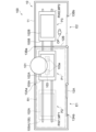
- FIG. 1 is a side view that diagrammatically illustrates an example (first example) of continuous casting equipment.
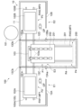
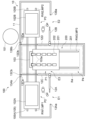
- FIG. 2 is a top view that diagrammatically illustrates an example (first example) of continuous casting equipment.
- FIG. 3 is a top view that diagrammatically illustrates an example (first example) of continuous casting equipment.
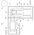
- FIG. 4 is a side view that diagrammatically shows another example (second example) of continuous casting equipment.
- FIG. 5 is a top view that diagrammatically illustrates another example (second example) of continuous casting equipment.
- FIG. 6 is a top view that diagrammatically illustrates another example (second example) of continuous casting equipment.
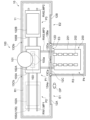
- FIG. 7 is a top view that diagrammatically shows another example (third example) of continuous casting equipment.
- FIG. 1 is a side view that diagrammatically illustrates an example (first example) of continuous casting equipment.
- FIG. 2 is a top view that diagrammatically illustrates an example (first example) of continuous casting equipment.
- FIG. 3 is a top view that diagrammatically illustrate
- FIG. 8 is a top view that diagrammatically illustrates another example (third example) of continuous casting equipment.
- FIG. 9 is a top view that diagrammatically illustrates another example (third example) of continuous casting equipment.
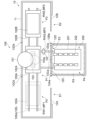
- FIG. 10 is a top view that diagrammatically illustrates another example (fourth example) of continuous casting equipment.
- FIG. 11 is a top view that diagrammatically illustrates another example (fourth example) of continuous casting equipment.
- FIG. 12 is a top view that diagrammatically illustrates another example (fourth example) of continuous casting equipment.
- FIG. 13 is a side view illustrating a schematic example of a blast furnace facility (fifth example).
- FIG. 14 is a top view illustrating a schematic example of a blast furnace facility (fifth example).
- FIG. 15 is a top view illustrating a schematic example of a blast furnace facility (fifth example).
- the continuous casting facility 100 includes a ladle 101, two tundishes 102A and 102B, a mold 103, a slab support roll 104, and two tundish cars 105A and 105B.
- the ladle 101 is a container for storing molten steel (molten metal).
- the two tundishes 102A and 102B are each positioned below the ladle 101 and are configured to store the molten steel that flows out from a nozzle 101a provided on the bottom wall of the ladle 101.
- the mold 103 is disposed on the floor surface FL.
- the mold 103 is configured to cool and mold the molten metal flowing out from the nozzles 102a provided on the bottom walls of the tundishes 102A and 102B into a predetermined shape while the tundishes 102A and 102B are positioned above the mold 103.
- the piece support rolls 104 are configured to transport the piece S pulled out of the mold 103 while cooling it.
- the continuous casting equipment 100 may be a multi-strand continuous casting equipment 100 in which multiple nozzles 102a are provided on the bottom walls of the tundishes 102A and 102B. In this case, each nozzle 102a is disposed in a corresponding opening 103a of the mold 103.
- the tundish cars 105A and 105B are configured to hold the tundishes 102A and 102B, respectively.
- the tundish cars 105A and 105B each include a plurality of wheels 105a configured to run on rails RW1 and RW2 provided on the floor surface FL.
- the rails RW1 and RW2 may each extend linearly along a predetermined direction (the left-right direction in Figures 2 and 3) such that one end is located near the mold 103 and the other end is located away from the mold 103.
- the tundish car 105A (first device, first traveling carriage) can travel between a casting position P1 (first position) directly above the mold 103 and a maintenance position P2 (second position) away from the mold 103 while holding the tundish 102A (first device, first tundish). That is, the tundish car 105A is configured to be movable along a rail RW1 extending between the casting position P1 and the maintenance position P2, which serves as a movement path MP1 (first movement path).
- the tundish car 105B (second device, second traveling carriage) can travel between a casting position P1 (third position) directly above the mold 103 and a maintenance position P3 (fourth position) away from the mold 103 while holding the tundish 102B (second device, second tundish). That is, the tundish car 105B is configured to be movable along a rail RW2 extending between the casting position P1 and the maintenance position P3, which serves as a movement path MP2 (second movement path).
- the casting position P1 of the tundish car 105A and the casting position P1 of the tundish car 105B are both directly above the mold 103, and are therefore in approximately the same position.
- the maintenance position P2 of the tundish car 105A is located to the left of the mold 103
- the maintenance position P3 of the tundish car 105B is located to the right of the mold 103.
- the maintenance position P2 of the tundish car 105A and the maintenance position P3 of the tundish car 105B are in different positions.
- the continuous casting equipment 100 is substantially entirely surrounded by a protective fence device 10. This prevents an operator OP from approaching the continuous casting equipment 100 during casting by the continuous casting equipment 100, thereby ensuring the safety of the operator OP.
- the protective fence device 10 includes a fixed fence 11, movable fences 12A and 12B, and detection units 13Aa, 13Ab, 13Ba, and 13Bb.
- the fixed fence 11 entirely surrounds the continuous casting equipment 100 except for the area in front of the maintenance positions P2 and P3, and is fixed to the floor surface FL.
- the fixed fence 11 includes an entrance/exit E1 (first entrance/exit) at a position in front of the maintenance position P2.
- the fixed fence 11 includes an entrance/exit E2 (second entrance/exit) at a position in front of the maintenance position P3.
- the movable fences 12A, 12B are configured to change the restricted access area and permitted access area within the fixed fence 11 as they move.
- the movable fence 12A first movable fence
- the movable fence 12B second movable fence
- the movable fence 12B is configured to be movable between a position where it closes the entrance/exit E2 that allows access to the tundish 102B and the tundish car 105B, and a position where it closes the travel path MP2, as illustrated in FIG. 2.
- the movable fence 12A may be attached to the fixed fence 11 near the entrance/exit E1 so as to be able to rotate.
- the movable fence 12B may be attached to the fixed fence 11 near the entrance/exit E2 so as to be able to rotate.
- the movable fences 12A, 12B may be configured to be extendable and contractable in their longitudinal directions. In this case, the movable fences 12A, 12B can be extended and contracted as necessary, which makes it possible to increase the mobility of the movable fences 12A, 12B when they move (when they rotate).
- the detection units 13Aa and 13Ab are configured to detect the locked state (opened or closed state) of the movable fence 12A.
- the detection units 13Aa and 13Ab may be configured to be able to electromagnetically lock and unlock the movable fence 12A.
- the detection unit 13Aa may be arranged on the fixed fence 11 so as to face the tip of the movable fence 12A when it is closing the space between the casting position P1 and the maintenance position P2, as exemplified in FIG. 3.
- the detection unit 13Ab may be arranged on the fixed fence 11 so as to face the tip of the movable fence 12A when it is closing the entrance E1, as exemplified in FIG. 2.
- the detection units 13Ba and 13Bb are configured to detect the locked state (opened or closed state) of the movable fence 12B.
- the detection units 13Ba and 13Bb may be configured to be able to electromagnetically lock and unlock the movable fence 12B.
- the detection unit 13Ba may be disposed on the fixed fence 11 so as to face the tip of the movable fence 12B in a state in which the space between the casting position P1 and the maintenance position P3 is closed.
- the detection unit 13Bb may be disposed on the fixed fence 11 so as to face the tip of the movable fence 12B in a state in which the entrance E2 is closed.
- a control unit may display the warning content on a display or the like, sound a warning from a speaker or the like, or automatically lock and unlock the movable fences 12A and 12B based on the detection signal.
- the area R1 is set as a restricted area where the worker OP cannot enter.
- the movable fence 12B rotates approximately 90° from the entrance E2 and extends to cross the rail RW2, so that the entrance E2 is open. Therefore, the area around the tundish car 105B is set as an accessible range where an operator OP can enter. At this time, maintenance of the tundish 102B and the tundish car 105B may be performed.
- the movable fence 12B closes the entrance E2 and the movable fence 12A closes the movement path MP1 between the casting position P1 and the maintenance position P2.
- the fixed fence 11 and the movable fences 12A, 12B surround the tundish car 105B together with the movement path MP2.
- the area R2 (second area) including the movement path MP2 is surrounded by the fixed fence 11 and the movable fences 12A, 12B together with the tundish car 105B.
- the area R2 is set as a restricted area where the worker OP cannot enter.
- the movable fence 12A rotates approximately 90° from the entrance E1 and extends to cross the rail RW1, so the entrance E1 is open. Therefore, the area around the tundish car 105A is set as an accessible range where the worker OP can enter. At this time, maintenance of the tundish 102A and the tundish car 105A may be performed.
- the movable fences 12A and 12B move in response to the change in the no-entry area for the worker OP accompanying the movement of the tundish cars 105A and 105B, so that the entry restriction to the no-entry area and the opening of the accessible area can be flexibly set. Therefore, in a continuous casting equipment 100 equipped with movable tundish cars 105A, 105B, it is possible to ensure the safety and workability of the worker OP even if the restricted entry area for the worker OP changes due to the movement of multiple devices.
- the movable fences 12A, 12B can be opened and closed at different positions by pivoting. Therefore, it is possible to open and close at multiple positions with a small number of movable fences 12A, 12B.
- the surrounding status of the areas R1 and R2 by the movable fences 12A and 12B is grasped according to the locking status of the movable fences 12A and 12B detected by the detection units 13Aa, 13Ab, 13Ba, and 13Bb.
- the detection unit 13Ab detects the closing status of the entrance E1 by the movable fence 12A
- the detection unit 13Ba detects the closing status of the movement path MP2 by the movable fence 12B
- the detection unit 13Aa detects the closing status of the movement path MP1 by the movable fence 12A and the detection unit 13Bb detects the closing status of the entrance E2 by the movable fence 12B, it can be determined that the area R2 is a restricted area. Therefore, it becomes possible to determine whether the tundish cars 105A and 105B can move in the areas R1 and R2.
- the protective fence device 10 of the present disclosure may also be applied to the continuous casting equipment 100 illustrated in Figures 4 to 6.
- the continuous casting equipment 100 of the example of Figures 4 to 6 differs from the continuous casting equipment 100 of the example of Figures 1 to 3 (hereinafter sometimes referred to as the "first example") in that it does not include a tundish 102B and a tundish car 105B, but does include a dummy bar insertion device 200.
- the continuous casting equipment 100 of the second example will be described, mainly focusing on the differences from the first example.
- the dummy bar insertion device 200 includes a dummy bar car 201 (second device, second running cart) and at least one dummy bar 202.
- the dummy bar car 201 is configured to hold at least one dummy bar 202. In a second example, the dummy bar car 201 holds two dummy bars 202 according to the number of openings 103a of the mold 103.
- the dummy bar car 201 includes a plurality of wheels 201a configured to be able to run on a rail RW3 provided on the floor surface FL. As illustrated in Figures 5 and 6, the rail RW3 may extend linearly along a predetermined direction (the vertical direction in Figures 5 and 6) so that one end is located near the mold 103 and the other end is located away from the mold 103. The rail RW3 may extend so as to intersect with the rail RW1.
- the dummy bar car 201 can move between an insertion position P1 (third position) of the dummy bar 202, which is near the mold 103, and a mounting position P4 (fourth position) of the dummy bar 202, which is away from the mold 103, while holding the dummy bar 202. That is, the dummy bar car 201 is configured to be movable along a rail RW3 extending between the insertion position P1 and the mounting position P4, which serves as a movement path MP3 (second movement path).
- the casting position P1 of the tundish car 105A and the insertion position P1 of the dummy bar 202 are approximately the same position.
- the maintenance position P2 of the tundish car 105A is located to the left of the mold 103, and the mounting position P4 of the dummy bar 202 is a different location from the mold 103.
- the maintenance position P2 of the tundish car 105A and the mounting position P4 of the dummy bar 202 are different positions.
- the dummy bar 202 held by the dummy bar car 201 is inserted from above into the mold 103 from the dummy bar car 201 before casting begins in the continuous casting equipment 100. This prevents molten steel from flowing out of the mold 103 when the molten steel is poured into the mold 103.
- the dummy bar 202 is pulled downward from the mold 103 by a pulling device (not shown), and moves downstream together with the slab S formed in the mold 103 by the slab support rolls 104.
- a transport device not shown
- the dummy bar 202 moves in one direction to circulate the dummy bar car 201, mold 103, cast piece support rolls 104, etc. During this movement, the dummy bar 202 needs to curve and bend along its movement path. For this reason, the dummy bar 202 is composed of multiple segments connected in a row. Adjacent segments are connected to each other so that they can rotate freely.
- the continuous casting equipment 100 according to the second example is also almost entirely surrounded by the guard fence device 10.
- the guard fence device 10 includes a fixed fence 11, movable fences 12A and 12C, and detection units 13Aa, 13Ca, and 13Cb.
- the guard fence device 10 according to the second example will be described, focusing mainly on the differences from the first example.
- the fixed fence 11 entirely surrounds the continuous casting equipment 100 except for the front of the maintenance position P2 and the front of the mold 103, and is fixed to the floor surface FL.
- the fixed fence 11 includes an entrance/exit E1 (entrance/exit) at a position directly in front of the maintenance position P2.
- the fixed fence 11 includes an opening E3 at a position directly in front of the mold 103.
- the movable fence 12A (movable fence section, first movable fence) is configured to be movable between a position that closes the entrance E1 (see FIG. 5) and a position that opens the entrance E1 (see FIG. 6).
- the movable fence 12A is configured to slide in its longitudinal direction (left-right direction in FIG. 5 and FIG. 6), but may be configured to be expandable and contractible in the longitudinal direction.
- the movable fence 12C (movable fence section, second movable fence) is configured to be movable between a position where it closes the travel path MP1 (see FIG. 6) and a position where it closes the travel path MP3 and also closes the opening E3 (see FIG. 5).
- the movable fence 12C may be attached to the fixed fence 11 near the opening E3 so that it can move in a swiveling manner.
- the movable fence 12C may be configured to be extendable and retractable in its longitudinal direction.
- the detection unit 13Aa may be arranged on the fixed fence 11 so as to face the tip of the movable fence 12A (the right end in FIG. 5) when the entrance/exit E1 is closed.
- the detection units 13Ca and 13Cb are configured to detect the locked state of the movable fence 12C.
- the detection units 13Ca and 13Cb may be configured to be able to electromagnetically lock and unlock the movable fence 12C.
- the detection unit 13Ca may be arranged on the fixed fence 11 so as to face the tip of the movable fence 12C in a state in which the gap between the casting position P1 and the mounting position P4 is closed, as illustrated in FIG. 5.
- the detection unit 13Cb may be arranged on the fixed fence 11 so as to face the tip of the movable fence 12C in a state in which the gap between the casting position P1 and the maintenance position P2 is closed, as illustrated in FIG. 6.
- the movable fence 12A closes the entrance/exit E1 and the movable fence 12C closes the movement path MP3 between the casting position P1 and the loading position P4.
- the fixed fence 11 and the movable fences 12A, 12C surround the tundish car 105A together with the movement path MP1
- the fixed fence 11 and the movable fence 12C surround the dummy bar car 201.
- the region R1 (first region) including the movement path MP1 is surrounded by the fixed fence 11 and the movable fences 12A, 12C together with the tundish car 105A.
- the area R3 between the casting position P1 and the mounting position P4 and on the mounting position P4 side is surrounded by the fixed fence 11 and the movable fence 12C along with the dummy barcar 201. Therefore, the areas R1 and R3 are set as restricted areas where the worker OP cannot enter.
- the movable fence 12A opens the entrance E1 and the movable fence 12C closes the movement path MP1 between the casting position P1 and the maintenance position P2.
- the fixed fence 11 and the movable fences 12A, 12C surround the dummy bar car 201 together with the movement path MP3.
- the area R4 (second area) including the movement path MP3 is surrounded by the fixed fence 11 and the movable fences 12A, 12C together with the dummy bar car 201.
- the area R4 is set as a restricted area where the worker OP cannot enter.
- the area around the tundish car 105A is set as an accessible area where the worker OP can enter.
- the ladle 101 may be moved to a position away from the mold 103, and the dummy bar 202 may be inserted from the dummy bar car 201 into the opening 103a of the mold 103. Maintenance of the tundish 102A and the tundish car 105A may also be performed.
- the protective fence device 10 of the present disclosure may also be applied to the continuous casting equipment 100 illustrated in Figures 7 to 9.
- the continuous casting equipment 100 of the example of Figures 7 to 9 (hereinafter sometimes referred to as the "third example") differs from the continuous casting equipment 100 of the first example in that it further includes a dummy bar insertion device 200.
- the configuration of the dummy bar insertion device 200 is similar to that of the continuous casting equipment 100 of the second example, and therefore a description thereof will be omitted.
- the continuous casting equipment 100 according to the third example is almost entirely surrounded by the guard fence device 10.
- the guard fence device 10 includes a fixed fence 11, movable fences 12A-12D, and detection units 13Aa, 13Ba, 13Ca, 13Cb, 13Da, and 13Db.
- the guard fence device 10 according to the third example will be described, focusing mainly on the differences from the first example.
- the fixed fence 11 entirely surrounds the continuous casting equipment 100 except for the front of the maintenance positions P2 and P3 and the front of the mold 103, and is fixed to the floor surface FL.
- the fixed fence 11 includes an entrance/exit E1 (entrance/exit) in a position directly in front of the maintenance position P2.
- the fixed fence 11 includes an entrance/exit E2 (second entrance/exit) in a position directly in front of the maintenance position P3.
- the fixed fence 11 includes an opening E3 in a position directly in front of the mold 103.
- the movable fence 12A (movable fence section) is configured to be movable between a position that closes the entrance E1 (see Figures 7 and 8) and a position that opens the entrance E1 (see Figure 9).
- the movable fence 12A is configured to slide in its longitudinal direction (left-right direction in Figures 7 to 9), but may also be configured to be expandable and contractible in the longitudinal direction.
- the movable fence 12B (movable fence section) is configured to be movable between a position that closes the entrance E2 (see Figures 7 and 9) and a position that opens the entrance E2 (see Figure 8).
- the movable fence 12B is configured to slide in its longitudinal direction (left-right direction in Figures 7 to 9), but may also be configured to be expandable and contractible in the longitudinal direction.
- the movable fence 12C (movable fence section) is configured to be movable between a position where it closes the travel path MP1 (see FIG. 9) and a position where it closes the travel path MP3 together with the movable fence 12D and closes the opening E3 (see FIG. 7 and FIG. 8).
- the movable fence 12C may be attached to the fixed fence 11 near the opening E3 so that it can move in a swiveling manner.
- the movable fence 12C may be configured to be extendable and retractable in its longitudinal direction.
- the movable fence 12D (movable fence section) is configured to be movable between a position where it closes the travel path MP2 (see FIG. 9) and a position where it closes the travel path MP3 together with the movable fence 12C and closes the opening E3 (see FIG. 7 and FIG. 8).
- the movable fence 12D may be attached to the fixed fence 11 near the opening E3 so that it can move in a swiveling manner.
- the movable fence 12D may be configured to be extendable and retractable in its longitudinal direction.
- the detection unit 13Aa may be disposed on the fixed fence 11 so as to face the tip of the movable fence 12A (the right end in FIG. 7) when the entrance E1 is closed.
- the detection unit 13Ba may be disposed on the fixed fence 11 so as to face the tip of the movable fence 12B (the left end in FIG. 7) when the entrance E2 is closed.
- the detectors 13Ca and 13Cb are configured to detect the locked state of the movable fence 12C.
- the detectors 13Ca and 13Cb may be configured to be able to electromagnetically lock and unlock the movable fence 12C.
- the detector 13Ca may be arranged at the tip of the movable fence 12C, as illustrated in Figs. 7 to 9.
- the detector 13Ca may be configured to cooperate with the detector 13Da to lock the movable fences 12C and 12D when the tips of the movable fences 12C and 12D face each other when the gap between the casting position P1 and the mounting position P4 is closed, as illustrated in Figs. 7 and 8.
- the detector 13Cb may be arranged on the fixed fence 11 so as to face the tip of the movable fence 12C when the gap between the casting position P1 and the maintenance position P2 is closed, as illustrated in Fig. 9.
- the detection units 13Da and 13Db are configured to detect the locked state of the movable fence 12D.
- the detection units 13Da and 13Db may be configured to be able to electromagnetically lock and unlock the movable fence 12D.
- the detection unit 13Da may be arranged at the tip of the movable fence 12D, as illustrated in Figs. 7 to 9.
- the detection unit 13Da may be configured to cooperate with the detection unit 13Ca to lock the movable fences 12C and 12D when the tips of the movable fences 12C and 12D face each other when the gap between the casting position P1 and the mounting position P4 is closed, as illustrated in Figs. 7 and 8.
- the detection unit 13Db may be arranged on the fixed fence 11 so as to face the tip of the movable fence 12D when the gap between the casting position P1 and the maintenance position P3 is closed, as illustrated in Fig. 9.
- the tundish car 105B When the tundish car 105B is stopped at the maintenance position P3 and the dummy bar car 201 is stopped at the loading position P4, and the tundish car 105A moves between the maintenance position P2 and the casting position P1, as illustrated in Figure 7, the movable fences 12A and 12B close the entrances E1 and E2, respectively, and the movable fences 12C and 12D close the movement path MP3 between the casting position P1 and the loading position P4. As a result, the fixed fence 11 and movable fences 12A-12D surround the tundish car 105A together with the movement path MP1.
- the region R1 including the movement path MP1 is surrounded by the fixed fences 11 and movable fences 12A-12D together with the tundish car 105A.
- the area R3 between the casting position P1 and the mounting position P4 and on the mounting position P4 side is surrounded by the fixed fence 11 and the movable fences 12C and 12D together with the dummy barcar 201. Therefore, the areas R1 and R3 are set as restricted areas where the worker OP cannot enter.
- the movable fences 12A and 12B may close the entrances E1 and E2, respectively, and the movable fences 12C and 12D may close the movement path MP3 between the casting position P1 and the loading position P4, in the same manner as described above.
- the fixed fence 11 and the movable fences 12A to 12D, together with the movement path MP2 surround the tundish car 105B.
- the region R1 including the movement path MP2 is surrounded by the fixed fences 11 and the movable fences 12A to 12D together with the tundish car 105B.
- the movable fences 12A and 12B may open the entrances E1 and E2, respectively, as illustrated in FIG. 8. Therefore, the periphery of the tundish cars 105A and 105B is set as an accessible range where the worker OP can enter. Also, when the dummy bar car 201 is stopped, the area R3 is surrounded by the fixed fence 11 and the movable fences 12C and 12D together with the dummy bar car 201. Therefore, the area R3 is set as a restricted area where the worker OP cannot enter.
- the tundish 102A and the tundish car 105A may be performed, or maintenance of the tundish 102B and the tundish car 105B may be performed.
- at least one of the movable fences 12A and 12B may close the entrances E1 and E2.
- the movable fences 12A and 12B open the entrances E1 and E2, respectively, the movable fence 12C closes the movement path MP1 between the casting position P1 and the maintenance position P2, and the movable fence 12D closes the movement path MP2 between the casting position P1 and the maintenance position P3.
- the fixed fence 11 and the movable fences 12C and 12D surround the dummy barker 201 together with the movement path MP3.
- the area R4 including the movement path MP3 is surrounded by the fixed fence 11 and the movable fences 12C and 12D together with the dummy barker 201. Therefore, the area R4 is set as a restricted area into which the worker OP cannot enter. Meanwhile, since the entrances E1 and E2 are open, the area around the tundish cars 105A and 105B is set as an accessible range for the worker OP. At this time, as illustrated in FIG. 9, the ladle 101 may be moved to a position away from the mold 103, and the dummy bar 202 may be inserted from the dummy bar car 201 to the opening 103a of the mold 103.
- the movable fences 12A and 12B may close the entrances E1 and E2.
- the protective fence device 10 of the present disclosure may also be applied to the continuous casting equipment 100 illustrated in Figures 10 to 12.
- the continuous casting equipment 100 in the example of Figures 10 to 12 (hereinafter, sometimes referred to as the "fourth example") is similar to the continuous casting equipment 100 in the third example, and therefore a description thereof will be omitted.
- the continuous casting equipment 100 according to the fourth example is also surrounded almost entirely by the guard fence device 10.
- the guard fence device 10 differs from the third example in that the configuration of the movable fences 12A, 12B is the same as that of the first example. That is, the movable fence 12A is configured to be movable between a position where it closes the entrance/exit E1 that allows access to the tundish 102A and the tundish car 105A (see FIG. 10) and a position where it closes the movement path MP1 (see FIG. 11).
- the movable fence 12B is configured to be movable between a position where it closes the entrance/exit E2 that allows access to the tundish 102B and the tundish car 105B (see FIG. 11) and a position where it closes the movement path MP2 (see FIG. 10).
- the protective fence device 10 includes detection units 13Aa, 13Ab, 13Ba, 13Bb, 13Ca, 13Cb, 13Da, and 13Db.
- the configurations of the detection units 13Aa, 13Ab, 13Ba, and 13Bb are similar to those in the first example, and therefore descriptions thereof will be omitted.
- the configurations of the detection units 13Ca, 13Cb, 13Da, and 13Db are similar to those in the third example, and therefore descriptions thereof will be omitted.
- the movable fence 12A closes the entrance/exit E1
- the movable fence 12B closes the movement path MP2 between the casting position P1 and the maintenance position P3
- the movable fences 12C and 12D close the movement path MP3 between the casting position P1 and the mounting position P4.
- the fixed fences 11 and the movable fences 12A to 12D surround the tundish car 105A together with the movement path MP1
- the fixed fences 11 and the movable fences 12C and 12D surround the dummy bar car 201.
- the tundish car 105A moves, the region R1 including the movement path MP1 is surrounded by the fixed fences 11 and the movable fences 12A to 12D together with the tundish car 105A.
- the area R3 between the casting position P1 and the mounting position P4 and on the mounting position P4 side is surrounded by the fixed fence 11 and the movable fences 12C and 12D together with the dummy bar car 201. Therefore, the areas R1 and R3 are set as restricted areas where the worker OP cannot enter.
- the movable fence 12B rotates approximately 90° from the entrance E2 and extends to cross the rail RW2, so the entrance E2 is open. Therefore, the area around the tundish car 105B is set as an accessible area where the worker OP can enter. At this time, maintenance of the tundish 102B and the tundish car 105B may be performed.
- the movable fence 12B closes the entrance/exit E2
- the movable fence 12A closes the movement path MP1 between the casting position P1 and the maintenance position P2
- the movable fences 12C and 12D close the movement path MP3 between the casting position P1 and the mounting position P4.
- the fixed fences 11 and the movable fences 12A to 12D surround the tundish car 105b together with the movement path MP2
- the fixed fences 11 and the movable fences 12C and 12D surround the dummy bar car 201.
- the region R2 including the movement path MP2 is surrounded by the fixed fences 11 and the movable fences 12A to 12D together with the tundish car 105B.
- the area R3 between the casting position P1 and the mounting position P4 and on the mounting position P4 side is surrounded by the fixed fence 11 and the movable fences 12C and 12D together with the dummy bar car 201. Therefore, the areas R2 and R3 are set as restricted areas where the worker OP cannot enter.
- the movable fence 12A rotates approximately 90° from the entrance E1 and extends to cross the rail RW2, so the entrance E1 is open. Therefore, the area around the tundish car 105A is set as an accessible area where the worker OP can enter. At this time, maintenance of the tundish 102A and the tundish car 105A may be performed.
- the movable fences 12A and 12B open the entrances E1 and E2, respectively, the movable fence 12C closes the movement path MP1 between the casting position P1 and the maintenance position P2, and the movable fence 12D closes the movement path MP2 between the casting position P1 and the maintenance position P3.
- the fixed fence 11 and the movable fences 12C and 12D surround the dummy barker 201 together with the movement path MP3.
- the area R4 including the movement path MP3 is surrounded by the fixed fence 11 and the movable fences 12C and 12D together with the dummy barker 201. Therefore, the area R4 is set as a restricted area into which the worker OP cannot enter. Meanwhile, since the entrances E1 and E2 are open, the periphery of the tundish cars 105A and 105B is set as an accessible range that the worker OP can enter. At this time, as illustrated in FIG. 12, the ladle 101 may be moved to a position away from the mold 103, and the dummy bar 202 may be inserted from the dummy bar car 201 to the opening 103a of the mold 103.
- the tundish 102A and the tundish car 105A may be performed, or maintenance of the tundish 102B and the tundish car 105B may be performed.
- at least one of the movable fences 12A and 12B may close the entrances E1 and E2.
- the protective fence device 10 of the present disclosure may also be applied to the blast furnace facility 300 illustrated in Figures 13 to 15.
- the blast furnace facility 300 illustrated in the example of Figures 13 to 15 (hereinafter, sometimes referred to as the "fifth example") includes a blast furnace 301, four tapping runners 302A to 302D, four work device units U1 to U4, and two cover moving devices 310A, 310B (first devices).
- the blast furnace 301 is a device that reduces iron ore to produce molten iron (molten pig iron).
- molten pig iron molten pig iron
- four tap holes are provided at the bottom of the blast furnace 301, depending on the number of tap runners 302 and working device units U.
- the tap runners 302A-302D are configured to separate the mixture of molten iron and slag discharged from the tap hole of the blast furnace 301 while allowing the molten iron to flow downstream. Therefore, the upstream parts of the tap runners 302A-302D are located near each tap hole of the blast furnace 301, and the downstream parts of the tap runners 302A-302D are located away from the blast furnace 301. In the fifth example, as illustrated in Figures 14 and 15, the four tap runners 302A-302D extend approximately radially from the blast furnace 301.
- the upstream portions of the tap runners 302A-302D include openings 302a (see Figures 13 and 15) that are open at the top, and are exposed outward from the floor surface FL at the openings 202a.
- the downstream portions of the tap runners 302A-302D extend below the floor surface FL.
- the working device units U1 to U4 are arranged around the blast furnace 301 so as to form a generally circular shape as a whole.
- the working device units U1 to U4 are arranged in this order clockwise when viewed from above.
- the working device units U1 and U2 are arranged adjacent to each other on the right side of the blast furnace 301.
- the working device units U3 and U4 are arranged adjacent to each other on the left side of the blast furnace 301. That is, in the example of Figs.
- the working device unit U1 is located at the upper right of the blast furnace 301, the working device unit U2 is located at the lower right of the blast furnace 301, the working device unit U3 is located at the lower left of the blast furnace 301, and the working device unit U1 is located at the upper left of the blast furnace 301.
- the working device units U1 to U4 are disposed near the corresponding tap chutes 302A to 302D.
- Each of the working device units U1 to U4 includes a tap hole opening device 320 (second device) and a tap hole closing device 330 (second device).
- the tap hole opening device 320 is configured to drill a refractory material blocking the tap hole of the blast furnace 301 to open the tap hole when tapping from the blast furnace 301 starts.
- the tap hole opening device 320 includes a base portion 321 and a drilling portion 322.
- the base portion 321 is configured to hold the drilling portion 322 and rotate the drilling portion 322 between a position where it is retracted from the tap hole of the blast furnace 301 (see FIG. 14) and a position where it faces the tap hole of the blast furnace 301 (see the working device unit U3 in FIG. 15).
- the drilling portion 322 is configured to drill the refractory material of the tap hole by driving a rod into the refractory material of the tap hole while facing the tap hole of the blast furnace 301.
- the tap hole blocking device 330 is configured to block the tap hole of the blast furnace 301 with mud material when tapping from the blast furnace 301 is completed.
- the tap hole blocking device 330 includes a base portion 331 and a mud gun 332.
- the base portion 331 is configured to hold the mud gun 332 and to move the mud gun 332 in a swiveling manner between a position where it is retracted from the tap hole of the blast furnace 301 (see FIG. 14) and a position where it faces the tap hole of the blast furnace 301 (see the working device unit U1 in FIG. 15).
- the mud gun 332 is configured to block the tap hole of the blast furnace 301 by discharging mud material from a discharge port into the tap hole while facing the tap hole.
- the cover moving devices 310A and 310B are each configured to cover from above the openings 202a of the tapping runners 302A to 302D through which molten iron flows during tapping from the blast furnace 301.
- the cover moving device 310A is disposed between the working device unit U1 and the working device unit U2 (between the tapping runner 302A and the tapping runner 302B).
- the cover moving device 310B is disposed between the working device unit U3 and the working device unit U4 (between the tapping runner 302C and the tapping runner 302D).
- Each of the cover moving devices 310A, 310B includes a base portion 311 and a tapping lane cover 312.
- the base portion 311 is configured to hold the tapping lane cover 312 and move the tapping lane cover 312 in a swiveling manner between a position retracted from the tapping lane 302A-302D (see FIG. 15) and a position above the opening 202a of the tapping lane 302A-302D (see working device units U1, U3 in FIG. 14).
- the tapping lane cover 312 is configured to prevent molten iron from splashing outward from the opening 202a during tapping from the blast furnace 301.
- the blast furnace facility 300 in the fifth example is also almost entirely surrounded by the protective fence device 10.
- the protective fence device 10 includes a fixed fence 11, movable fences 12A to 12F, and detection units 13A to 13F.
- the fixed fence 11 includes a central fence 11A and side fences 11B and 11C. As illustrated in Figures 14 and 15, the central fence 11A extends between the working device units U1 and U2 and the working device units U3 and U4, separating them.
- the side fence 11B is connected to the outer end of the central fence 11A, and extends to the right of the blast furnace 301 in the drawing so as to cover the sides of the working device units U1 and U2 and to widen the farther it gets from the blast furnace 301.
- the side fence 11C is connected to the outer end of the central fence 11A, and extends to the left of the blast furnace 301 in the drawing so as to cover the sides of the working device units U3 and U4 and to widen the farther it gets from the blast furnace 301.
- the movable fence 12A is configured to be movable between a position where it closes the gap between the working device unit U1 and the working device unit U2 (see FIG. 15) and a position where it opens this gap (see FIG. 14).
- the movable fence 12A is configured to be expandable and contractible in its longitudinal direction (left and right directions in FIG. 14 and FIG. 15) between these gaps.
- the movable fence 12B is configured to be movable between a position (see FIG. 15) in which it closes the gap between the tip of the side fence 11B located to the side of the working device unit U1 and the outer end of the movable fence 12A, and a position (not shown) in which it opens this gap.
- the movable fence 12B is configured to be expandable and contractible between this gap in its longitudinal direction (the direction intersecting with the tapping basin 302A).
- the movable fence 12C is configured to be movable between a position (see FIG. 14) in which it closes the gap between the tip of the side fence 11B located to the side of the working device unit U2 and the outer end of the movable fence 12A, and a position (see FIG. 15) in which it opens this gap.
- the movable fence 12C is configured to be expandable and contractible between this gap in its longitudinal direction (the direction intersecting with the tapping basin 302B).
- the movable fence 12D is configured to be movable between a position where it closes the gap between the working device unit U3 and the working device unit U4 (see FIG. 15) and a position where it opens this gap (see FIG. 14).
- the movable fence 12D is configured to be expandable and contractible between the gap in its longitudinal direction (left and right directions in FIG. 14 and FIG. 15).
- the movable fence 12E is configured to be movable between a position (see FIG. 15) in which it closes the gap between the tip of the side fence 11B located to the side of the working device unit U3 and the outer end of the movable fence 12D, and a position (not shown) in which it opens this gap.
- the movable fence 12E is configured to be expandable and contractible between this gap in its longitudinal direction (the direction intersecting with the tapping basin 302C).
- the movable fence 12F is configured to be movable between a position (see FIG. 14) in which it closes the gap between the tip of the side fence 11B located to the side of the working device unit U4 and the outer end of the movable fence 12D, and a position (see FIG. 15) in which it opens this gap.
- the movable fence 12F is configured to be expandable and contractible between this gap in its longitudinal direction (the direction intersecting with the tapping basin 302D).
- the detection units 13A to 13F are configured to detect the locked state (open or closed state) of the movable fences 12A to 12F, respectively.
- the detection units 13A to 13F may be configured to be able to electromagnetically lock and unlock the movable fences 12A to 12F, respectively.
- the detection units 13A to 13F may be disposed at the tip of the movable fences 12A to 12F, respectively.
- the region R5 including the movement path is surrounded by the fixed fence 11 and the movable fences 12A to 12C together with the cover moving device 310A. Therefore, the area R5 is set as a restricted area where the worker OP cannot enter. As illustrated in FIG.
- the fixed fence 11 and the movable fences 12D to 12F may surround the cover moving device 310B together with the movement path of the tapping lane cover 312 of the cover moving device 310B.
- the tap hole opening device 320 of the working device unit U1 When the tap hole opening device 320 of the working device unit U1 is retracted from the tap hole of the blast furnace 301, the tap hole cover 312 of the cover moving device 310A is retracted from the tap hole 302A, and the mud gun 332 of the tap hole closing device 330 of the working device unit U1 moves between the retracted position of the tap hole of the blast furnace 301 and the facing position, the movable fences 12A and 12B are closed as illustrated in Figure 15. As a result, the fixed fence 11 and the movable fences 12A and 12B surround the tap hole closing device 330 together with the movement path of the mud gun 332 of the tap hole closing device 330 of the working device unit U1.
- the area R6 including the movement path is surrounded by the fixed fence 11 and the movable fences 12A, 12B together with the tap hole closing device 330. Therefore, the area R6 is set as a restricted area where the worker OP cannot enter.
- the movable fence 12C may be opened, and the area around the working device unit U2 and the tapping chute 302B may be set as an accessible area where the worker OP can enter.
- the area including the movement path of the mud gun 332 may be surrounded by the fixed fence 11 and the movable fences 12A, 12C to 12F in the same manner as described above.
- the tap hole closing device 330 of the working device unit U3 When the tap hole closing device 330 of the working device unit U3 is retracted from the tap hole of the blast furnace 301, the tap hole cover 312 of the cover moving device 310B is retracted from the tap hole 302C, and the drilling section 322 of the tap hole opening device 320 of the working device unit U3 moves between the retracted position and the facing position of the tap hole of the blast furnace 301, the movable fences 12D, 12E are closed as illustrated in Figure 15. As a result, the fixed fence 11 and the movable fences 12D, 12E surround the tap hole opening device 320 together with the movement path of the drilling section 322 of the tap hole opening device 320 of the working device unit U3.
- the area R7 including the movement path is surrounded by the fixed fence 11 and the movable fences 12D, 12E together with the tap hole opening device 320. Therefore, the area R7 is set as a restricted area where the worker OP cannot enter.
- the movable fence 12F may be opened, and the area around the working device unit U4 and the tapping runner 302D may be set as an accessible area where the worker OP can enter.
- the drilling section 322 of the tap hole opening device 320 of the working device units U1, U2, U4 moves between the retreat position and the facing position of the tap hole of the blast furnace 301, the area including the movement path of the drilling section 322 may be surrounded by the fixed fence 11 and the movable fences 12A to 12D, 12F in the same manner as described above.
- the protective fence device 10 according to the present disclosure may also be applied to manufacturing equipment in which multiple pieces of equipment are movable.
- the area including the movement path of each piece of equipment is surrounded by the protective fence device 10 by moving the movable fence according to each area. Therefore, even if the no-entry range for workers changes as multiple pieces of equipment move, it is possible to ensure the safety and workability of the workers.
- the protective fence device 10 pre-sets the no-entry range corresponding to the equipment that is moving, it is possible to more effectively prevent contact between the worker OP and the equipment when multiple pieces of movable equipment are heavy objects that are difficult to stop instantly.
- An example of a protective fence device is a protective fence device installed to surround a manufacturing facility including a first device that can move along a first movement path between a first position and a second position, and a second device that can move along a second movement path between a third position and a fourth position.
- An example of a protective fence device includes a movable fence unit configured to surround a first area including the first movement path together with the first device when the first device moves, and to surround a second area including the second movement path together with the second device when the second device moves. In this case, when the first device moves, the first area becomes a restricted area, so the movable fence unit surrounds the first area including the first movement path together with the first device.
- the second device moves, the second area becomes a restricted access area, and the movable fence section surrounds the second area including the second movement path together with the second device. Therefore, the worker is prevented from approaching the vicinity of the second device.
- the movable fence section moves in response to the change in the restricted access area for the worker accompanying the movement of the multiple devices, so that the restriction of entry to the restricted access area and the opening of the accessible area are flexibly set. Therefore, in a manufacturing facility equipped with multiple movable devices, it is possible to ensure the safety and operability of the worker even if the restricted access area for the worker changes with the movement of the multiple devices.
- the manufacturing equipment may be a continuous casting equipment, including a first and a second tundish configured to store molten metal, and a mold configured to form the molten metal supplied from each of the first and second tundishes into a predetermined shape while cooling it
- the first equipment may be a first traveling carriage configured to hold the first tundish and travel along a first moving path between a first position above the mold (P1) and a second position away from the mold (P2)
- the second equipment may be a second traveling carriage configured to hold the second tundish and travel along a second moving path between a third position above the mold (P3) and a fourth position away from the mold (P4).
- the restricted area for workers changes due to the movement of multiple traveling carriages in the continuous casting equipment, it is possible to ensure the safety and operability of workers.
- the movable fence section may include a first movable fence configured to be pivotable between a position that closes the first travel path and a position that closes the first entrance/exit that allows access to the first device, and a second movable fence configured to be pivotable between a position that closes the second travel path and a position that closes the second entrance/exit that allows access to the second device.
- the first and second movable fences pivot, allowing the first and second movable fence sections to be opened and closed at different positions. Therefore, it is possible to achieve opening and closing at multiple positions with a small number of movable fence sections.
- the manufacturing equipment is a continuous casting equipment, and includes a tundish configured to store molten metal, and a mold configured to form the molten metal supplied from the tundish into a predetermined shape while cooling it
- the first equipment is a first traveling carriage configured to hold the tundish and travel on a first moving path between a first position above the mold (P1) and a second position away from the mold (P2)
- the second equipment may be a second traveling carriage configured to hold a dummy bar configured to be able to close the mold opening and travel on a second moving path between a third position above the mold (P3) and a fourth position away from the mold (P4).
- the restricted area for workers changes due to the movement of multiple traveling carriages in the continuous casting equipment, it is possible to ensure the safety and operability of workers.
- the movable fence section may include a first movable fence configured to be capable of opening and closing an entrance that allows access to the first device, and a second movable fence configured to be rotatable between a position that closes the first travel path and a position that closes the second travel path.
- the second movable fence can rotatably move to open and close the travel path at different positions with one movable fence. Therefore, it is possible to achieve opening and closing at multiple positions with a small number of movable fences.
- the manufacturing equipment is a blast furnace facility, and includes a blast furnace and first and second tapping runners extending horizontally from the blast furnace, the first device being a cover moving device including a tapping runner cover that is movable along a first moving path between a first position above the first tapping runner and a second position above the second tapping runner, and the second device may be a tapping runner closing device or a tapping runner opening device that is movable along a second moving path between a third position near the tapping runner of the blast furnace and a fourth position away from the tapping runner of the blast furnace.
- the first device being a cover moving device including a tapping runner cover that is movable along a first moving path between a first position above the first tapping runner and a second position above the second tapping runner
- the second device may be a tapping runner closing device or a tapping runner opening device that is movable along a second moving path between a third position near the tapping runner of the blast furnace and a fourth position away from the tapping runner of the
- the movable fence section may include a first movable fence configured to be capable of opening and closing an entrance that allows access to the first device, and a second movable fence configured to be capable of opening and closing the first travel path.
- Example 8 Any of the devices in Examples 1 to 7 may further include a detection unit configured to detect the locked state of the movable fence unit. In this case, the state in which the movable fence unit surrounds the first area or the second area is understood depending on the locked state detected by the detection unit. Therefore, it becomes possible to determine whether the first device or the second device can be moved.
- a detection unit configured to detect the locked state of the movable fence unit. In this case, the state in which the movable fence unit surrounds the first area or the second area is understood depending on the locked state detected by the detection unit. Therefore, it becomes possible to determine whether the first device or the second device can be moved.
- Example 9 In any of the devices of Examples 1 to 8, the movable fence section may be configured to be extendable. In this case, the movable fence section can be extended or retracted as necessary, which makes it possible to increase the mobility of the movable fence section when it is moved.
- the protective fence device disclosed herein makes it possible to ensure the safety and workability of workers in a manufacturing facility equipped with multiple movable devices, even when the restricted access area for workers changes as the multiple devices move.
- 10...protective fence device 12A...movable fence (movable fence section, first movable fence), 12B...movable fence (movable fence section, second movable fence), 12C...movable fence (movable fence section, second movable fence), 13A to 13F, 13Aa, 13Ab, 13Ba, 13Bb, 13Ca, 13Cb, 13Da, 13Db...detection section, 100...continuous casting equipment (manufacturing equipment), 102A...tundish (first equipment, first tundish), 102B...tundish (second equipment, second tundish), 103...mold, 103a...opening, 105A...tundish car (first equipment, first traveling car), 105B...tundish car (second equipment, second traveling car), 200...dummy bar insertion device, 201...dummy bar car (second device, second traveling car), 202...
- dummy bar 300... blast furnace equipment, 301... blast furnace, 302A... tapping lane (first tapping lane), 302B... tapping lane (second tapping lane), 310A, 310B... cover moving device (first device), 312... tapping lane cover, 320... tapping hole opening device (second device), 330... tapping hole closing device (second device), E1...
Landscapes
- Engineering & Computer Science (AREA)
- Chemical & Material Sciences (AREA)
- Manufacturing & Machinery (AREA)
- Materials Engineering (AREA)
- Metallurgy (AREA)
- Organic Chemistry (AREA)
- Civil Engineering (AREA)
- Structural Engineering (AREA)
- Mechanical Engineering (AREA)
- Continuous Casting (AREA)
Priority Applications (1)
| Application Number | Priority Date | Filing Date | Title |
|---|---|---|---|
| JP2025504636A JP7709108B2 (ja) | 2023-07-05 | 2024-07-04 | 防護柵装置 |
Applications Claiming Priority (2)
| Application Number | Priority Date | Filing Date | Title |
|---|---|---|---|
| JP2023-110520 | 2023-07-05 | ||
| JP2023110520 | 2023-07-05 |
Publications (1)
| Publication Number | Publication Date |
|---|---|
| WO2025009601A1 true WO2025009601A1 (ja) | 2025-01-09 |
Family
ID=94171620
Family Applications (1)
| Application Number | Title | Priority Date | Filing Date |
|---|---|---|---|
| PCT/JP2024/024330 Pending WO2025009601A1 (ja) | 2023-07-05 | 2024-07-04 | 防護柵装置 |
Country Status (2)
| Country | Link |
|---|---|
| JP (1) | JP7709108B2 (https=) |
| WO (1) | WO2025009601A1 (https=) |
Citations (5)
| Publication number | Priority date | Publication date | Assignee | Title |
|---|---|---|---|---|
| JPS58185351U (ja) * | 1982-06-04 | 1983-12-09 | 川崎製鉄株式会社 | 連続鋳造機 |
| JPH0733443U (ja) * | 1993-11-22 | 1995-06-20 | 日本鋼管株式会社 | 連続鋳造設備のタンディッシュ傾転装置 |
| JP2020006385A (ja) * | 2018-07-04 | 2020-01-16 | 株式会社神戸製鋼所 | 連続鋳造設備 |
| CN113523265A (zh) * | 2020-04-21 | 2021-10-22 | 烟台冰轮智能机械科技有限公司 | 一种智能熔炼系统及其作业方法 |
| CN116146495A (zh) * | 2023-02-01 | 2023-05-23 | 苏州昊岳科技有限公司 | 一种喷油螺杆式真空泵 |
Family Cites Families (4)
| Publication number | Priority date | Publication date | Assignee | Title |
|---|---|---|---|---|
| JPH10211561A (ja) * | 1997-01-29 | 1998-08-11 | Hitachi Zosen Corp | ピット用柵体を有する連続鋳造設備 |
| JP2017140628A (ja) | 2016-02-09 | 2017-08-17 | 中日本鋳工株式会社 | 溶解炉用防護柵 |
| JP2021037517A (ja) | 2019-08-30 | 2021-03-11 | 住友金属鉱山株式会社 | 傾動式溶解炉の防護柵構造及びこれを用いた傾動式溶解炉設備 |
| CN216332072U (zh) | 2021-11-30 | 2022-04-19 | 临沂鑫海新型材料有限公司 | 一种浇铸行车安全登机通道 |
-
2024
- 2024-07-04 JP JP2025504636A patent/JP7709108B2/ja active Active
- 2024-07-04 WO PCT/JP2024/024330 patent/WO2025009601A1/ja active Pending
Patent Citations (5)
| Publication number | Priority date | Publication date | Assignee | Title |
|---|---|---|---|---|
| JPS58185351U (ja) * | 1982-06-04 | 1983-12-09 | 川崎製鉄株式会社 | 連続鋳造機 |
| JPH0733443U (ja) * | 1993-11-22 | 1995-06-20 | 日本鋼管株式会社 | 連続鋳造設備のタンディッシュ傾転装置 |
| JP2020006385A (ja) * | 2018-07-04 | 2020-01-16 | 株式会社神戸製鋼所 | 連続鋳造設備 |
| CN113523265A (zh) * | 2020-04-21 | 2021-10-22 | 烟台冰轮智能机械科技有限公司 | 一种智能熔炼系统及其作业方法 |
| CN116146495A (zh) * | 2023-02-01 | 2023-05-23 | 苏州昊岳科技有限公司 | 一种喷油螺杆式真空泵 |
Also Published As
| Publication number | Publication date |
|---|---|
| JPWO2025009601A1 (https=) | 2025-01-09 |
| JP7709108B2 (ja) | 2025-07-16 |
Similar Documents
| Publication | Publication Date | Title |
|---|---|---|
| JP7709108B2 (ja) | 防護柵装置 | |
| CN102027305B (zh) | 熔炉设备 | |
| US6079479A (en) | Twin roll continuous casting installation | |
| DE19740536B4 (de) | Bandgießen | |
| US3558256A (en) | Apparatus for the continuous casting of metals | |
| KR101224014B1 (ko) | 턴디쉬의 주입노즐 급속 폐쇄 장치 및 방법 | |
| JP2020006385A (ja) | 連続鋳造設備 | |
| KR101299745B1 (ko) | 전기로의 슬래그 유출방지장치 | |
| KR101408220B1 (ko) | 몰드플럭스 제거장치 및 이를 포함하는 연속주조장치 | |
| KR20180020732A (ko) | 보호장치 및 이를 구비하는 운반장치 | |
| US7048032B2 (en) | Device for continuously casting molten metals | |
| JP2017140628A (ja) | 溶解炉用防護柵 | |
| KR101481602B1 (ko) | 연속주조용 턴디쉬 및 연속주조장치 | |
| KR102288412B1 (ko) | 첨가제 투입장치 및 첨가제 투입방법 | |
| CN115989127A (zh) | 注射成型机 | |
| JPS61105094A (ja) | 溶鉱炉あるいは鋳鍋からの溶解金属を通す底部流出口に使用する装置 | |
| KR101961831B1 (ko) | 침지노즐용 용강 비산방지장치 | |
| KR101140278B1 (ko) | 토치절단장치 | |
| KR101560620B1 (ko) | 대탕도 커버 장치 | |
| KR20130034390A (ko) | 턴디쉬 플럭스 공급 장치 | |
| KR200254191Y1 (ko) | 턴디쉬 비상 크로스시의 노즐 막힘 방지장치 | |
| KR20250032050A (ko) | 더미바 헤드 및 이를 갖는 연속주조설비 | |
| KR102038648B1 (ko) | 주조장치 | |
| JPH0437441A (ja) | タンデイツシユの溶鋼排出用開口の閉塞方法および装置 | |
| JPH0750042Y2 (ja) | 連続鋳造設備におけるタンディッシュの残鋼滓排出装置 |
Legal Events
| Date | Code | Title | Description |
|---|---|---|---|
| WWE | Wipo information: entry into national phase |
Ref document number: 2025504636 Country of ref document: JP |
|
| 121 | Ep: the epo has been informed by wipo that ep was designated in this application |
Ref document number: 24836113 Country of ref document: EP Kind code of ref document: A1 |
|
| WWE | Wipo information: entry into national phase |
Ref document number: 202517102540 Country of ref document: IN |
|
| WWP | Wipo information: published in national office |
Ref document number: 202517102540 Country of ref document: IN |
|
| NENP | Non-entry into the national phase |
Ref country code: DE |