WO2025009593A1 - 液圧発生装置 - Google Patents
液圧発生装置 Download PDFInfo
- Publication number
- WO2025009593A1 WO2025009593A1 PCT/JP2024/024245 JP2024024245W WO2025009593A1 WO 2025009593 A1 WO2025009593 A1 WO 2025009593A1 JP 2024024245 W JP2024024245 W JP 2024024245W WO 2025009593 A1 WO2025009593 A1 WO 2025009593A1
- Authority
- WO
- WIPO (PCT)
- Prior art keywords
- intermediate member
- hydraulic pressure
- control
- piston
- cylinder
- Prior art date
- Legal status (The legal status is an assumption and is not a legal conclusion. Google has not performed a legal analysis and makes no representation as to the accuracy of the status listed.)
- Ceased
Links
Images

Classifications
-
- B—PERFORMING OPERATIONS; TRANSPORTING
- B60—VEHICLES IN GENERAL
- B60T—VEHICLE BRAKE CONTROL SYSTEMS OR PARTS THEREOF; BRAKE CONTROL SYSTEMS OR PARTS THEREOF, IN GENERAL; ARRANGEMENT OF BRAKING ELEMENTS ON VEHICLES IN GENERAL; PORTABLE DEVICES FOR PREVENTING UNWANTED MOVEMENT OF VEHICLES; VEHICLE MODIFICATIONS TO FACILITATE COOLING OF BRAKES
- B60T13/00—Transmitting braking action from initiating means to ultimate brake actuator with power assistance or drive; Brake systems incorporating such transmitting means, e.g. air-pressure brake systems
- B60T13/10—Transmitting braking action from initiating means to ultimate brake actuator with power assistance or drive; Brake systems incorporating such transmitting means, e.g. air-pressure brake systems with fluid assistance, drive, or release
- B60T13/12—Transmitting braking action from initiating means to ultimate brake actuator with power assistance or drive; Brake systems incorporating such transmitting means, e.g. air-pressure brake systems with fluid assistance, drive, or release the fluid being liquid
- B60T13/14—Transmitting braking action from initiating means to ultimate brake actuator with power assistance or drive; Brake systems incorporating such transmitting means, e.g. air-pressure brake systems with fluid assistance, drive, or release the fluid being liquid using accumulators or reservoirs fed by pumps
- B60T13/148—Arrangements for pressure supply
-
- B—PERFORMING OPERATIONS; TRANSPORTING
- B60—VEHICLES IN GENERAL
- B60T—VEHICLE BRAKE CONTROL SYSTEMS OR PARTS THEREOF; BRAKE CONTROL SYSTEMS OR PARTS THEREOF, IN GENERAL; ARRANGEMENT OF BRAKING ELEMENTS ON VEHICLES IN GENERAL; PORTABLE DEVICES FOR PREVENTING UNWANTED MOVEMENT OF VEHICLES; VEHICLE MODIFICATIONS TO FACILITATE COOLING OF BRAKES
- B60T8/00—Arrangements for adjusting wheel-braking force to meet varying vehicular or ground-surface conditions, e.g. limiting or varying distribution of braking force
- B60T8/32—Arrangements for adjusting wheel-braking force to meet varying vehicular or ground-surface conditions, e.g. limiting or varying distribution of braking force responsive to a speed condition, e.g. acceleration or deceleration
- B60T8/34—Arrangements for adjusting wheel-braking force to meet varying vehicular or ground-surface conditions, e.g. limiting or varying distribution of braking force responsive to a speed condition, e.g. acceleration or deceleration having a fluid pressure regulator responsive to a speed condition
- B60T8/42—Arrangements for adjusting wheel-braking force to meet varying vehicular or ground-surface conditions, e.g. limiting or varying distribution of braking force responsive to a speed condition, e.g. acceleration or deceleration having a fluid pressure regulator responsive to a speed condition having expanding chambers for controlling pressure, i.e. closed systems
Definitions
- the vehicle is equipped with a brake control device SC.
- the brake control device SC employs a so-called front and rear type (also called “type II") brake system as its two systems.
- the brake control device SC adjusts the actual wheel pressure Pw of each wheel cylinder CW.
- the brake control device SC is composed of two brake units SA and SB.
- the first actuator YA is composed of an apply unit AP, a hydraulic pressure generating unit PS, and an input unit NR.
- a master piston NM is inserted into the single-type master cylinder CM.
- the interior of the master cylinder CM is divided into three hydraulic chambers Rm, Ru, and Rs by the master piston NM.
- the master chamber Rm is formed by the bottom of the master cylinder CM and the master piston NM.
- the interior of the master cylinder CM is divided into a servo chamber Ru and a reaction chamber Rs by the flange portion Tu of the master piston NM.
- the pressure-receiving area rm of the master chamber Rm and the pressure-receiving area ru of the servo chamber Ru are set to be equal.
- the master piston NM When braking is not in progress, the master piston NM is in the most retracted position (i.e., the position where the volume of the master chamber Rm is maximum). In this state, the master chamber Rm of the master cylinder CM is connected to the master reservoir RV. Brake fluid BF is stored inside the master reservoir RV (also called the "atmospheric pressure reservoir"). When the brake operating member BP is operated, the master piston NM is moved forward in the direction Da (the direction in which the volume of the master chamber Rm decreases). This movement blocks communication between the master chamber Rm and the master reservoir RV.
- the supply pressure Pm (the internal pressure of the master chamber Rm, also called the "master pressure") is increased from “0 (atmospheric pressure)".
- the brake fluid BF pressurized to the supply pressure Pm is output (pressurized) from the master cylinder CM (particularly the master chamber Rm).
- the supply path HH is cut off. This causes the hydraulic pressure generating unit PS and the master reservoir RV to be in a non-communicative state.
- the servo pressure Pc is supplied to the servo chamber Ru to generate a supply pressure Pm (master pressure).
- the supply pressure Pm generates a hydraulic pressure Pwf (front wheel pressure) in the front wheel cylinder CWf.
- the servo pressure Pc is directly supplied to the rear wheel cylinder CWr to generate a hydraulic pressure Pwr (rear wheel pressure) in the rear wheel cylinder CWr.
- the hydraulic pressure generating unit PS is provided with a servo pressure sensor PC to detect the servo pressure Pc. Details of the hydraulic pressure generating unit PS will be described later.
- the first control valve VA When no power is supplied (energized) to the first and second control valves VA and VB, the first control valve VA is closed and the second control valve VB is open.
- the input chamber Rn When the first control valve VA is closed, the input chamber Rn is sealed and fluid locked. This causes the master piston NM to displace integrally with the brake operating member BP.
- the second control valve VB When the second control valve VB is open, the stroke simulator SS and the reaction chamber Rs are connected to the master reservoir RV.
- a first actuator YA is controlled by a first controller EA.
- the first controller EA is composed of a microprocessor MP and a drive circuit DR.
- the first controller EA is connected to a communication bus BS so that signals (detection values, calculation values, control flags, etc.) can be shared between the first controller EA and other controllers (EB, EG, etc.).
- Various signals such as the operation displacement Sp (detection value of the operation displacement sensor SP), input pressure Pn (detection value of the input pressure sensor PN), servo pressure Pc (detection value of the servo pressure sensor PC), and motor rotation angle Ka (detection value of the rotation angle sensor KA) are directly input to the first controller EA.
- various signals such as the supply pressure Pm and the limit regenerative braking force Fx are input to the first controller EA from the communication bus BS.
- the first controller EA outputs the target regenerative braking force Fh (target value of the regenerative braking force Fg) to the communication bus BS.
- the regenerative controller EG controls the regenerative braking force Fg (actual value) based on the target regenerative braking force Fh (target value) obtained from the communication bus BS.
- the first controller EA (particularly the microprocessor MP) is programmed with a pressure regulation control algorithm.
- the drive circuit DR drives the electric motor MT and various solenoid valves (VA, etc.).
- the drive circuit DR includes an H-bridge circuit (also called an "inverter circuit") made of switching elements (e.g., MOS-FETs) to drive the electric motor MT.
- the drive circuit DR also includes switching elements to drive the various solenoid valves.
- the drive circuit DR includes a motor current sensor (not shown) that detects the supply current Im (also called the "motor current") to the electric motor MT.
- the electric motor MT is provided with a rotation angle sensor KA to detect the position Ka (rotation angle) of the motor shaft SM.
- the drive signals Va, Vb of the first and second control valves VA, VB, and the drive signal Mt of the electric motor MT are calculated.
- the switching elements are driven in response to the various drive signals (Mt, etc.).
- the target pressure Pt is calculated based on the operation displacement Sp, etc.
- the "target pressure Pt" is a target value corresponding to the servo pressure Pc (actual value).
- the electric motor MT is controlled in response to the target pressure Pt and the drive signal Mt calculated based on the servo pressure Pc so that the servo pressure Pc (actual value) approaches and matches the target pressure Pt (target value).
- the supply pressure Pm and the servo pressure Pc are adjusted (increased or decreased) and output as hydraulic pressures Pwf, Pwr (front and rear wheel pressures) of the front and rear wheel cylinders CWf, CWr.
- the configuration of the second brake unit SB is known, so a description thereof will be omitted.
- the operation of the second actuator YB (electric motor, fluid pump, solenoid valve, etc.) is stopped. Therefore, the supply pressure Pm is output from the second braking unit SB as the front wheel pressure Pwf, and the servo pressure Pc is output as the rear wheel pressure Pwr.
- the forward rotation direction Hs of the electric motor MT corresponds to the forward direction Ha of the linear member BD. Therefore, the rotational motion of the electric motor MT in the reverse direction Hg corresponds to the backward direction Hb of the linear member BD.
- the linear member BD moves in the forward direction Ha. This reduces the volume of the control chamber Rc and increases the servo pressure Pc.
- the electric motor MT rotates in the reverse direction Hg, the linear member BD moves in the backward direction Hb. This increases the volume of the control chamber Rc and decreases the servo pressure Pc.
- the housing HG holds the components (MT, GS, etc.) that make up the hydraulic pressure generating unit PS.
- the housing HG is divided into multiple parts so that the components can be assembled.
- the housing HG is divided into a cylinder housing HGc and a motor housing HGm.
- the motor housing HGm and the cylinder housing HGc are assembled and ultimately integrated into the housing HG.
- the housing HG is a collective term for the cylinder housing HGc and the motor housing HGm.
- the housing HG may be integrated with the first controller EA.
- the first controller EA is composed of a control board on which the microprocessor MP and the drive circuit DR are mounted, and a controller housing (not shown) that houses it.
- the controller housing is then assembled and integrated with the housing HG.
- the reduction gear GS and the conversion mechanism GH are held by the housing HG (particularly, the cylinder housing HGc).
- the electric motor MT is also held by the housing HG (particularly, the motor housing HGm).
- a control cylinder CC (corresponding to a "cylinder") is formed in the housing HG (particularly, the cylinder housing HGc).
- a control piston NC (corresponding to a "piston”) is inserted into the control cylinder CC.
- the control cylinder CC and the control piston NC form a control chamber Rc (hydraulic chamber).
- a discharge section Au is provided in the control cylinder CC (particularly, the control chamber Rc).
- the discharge section Au is connected to the servo path HU and the rear wheel connection path HSr. That is, the control chamber Rc is connected to the servo chamber Ru and the rear wheel cylinder CWr.
- the servo pressure Pc is supplied (output) to the servo chamber Ru and the rear wheel cylinder CWr.
- the electric motor MT is a power source (pressurizing source) for generating the servo pressure Pc (hydraulic pressure in the control cylinder CC).
- power refers to the energy required to move the movable members (BK, BD, etc.) in the hydraulic pressure generating unit PS.
- power is defined as a physical quantity, energy per unit time (also called “power”).
- the electric motor MT outputs a rotational power Tm (also called “first rotational power”).
- the rotational power Tm of the electric motor MT is the axial torque of the electric motor MT multiplied by the rotational speed of the electric motor MT (particularly the motor shaft SM).
- the linear power Fn of the linear member BD (described later) is the thrust of the linear member BD (force acting in the axial direction Hj) multiplied by the linear speed of the linear member BD (speed in the axial direction Hj).
- a three-phase brushless motor is used as the electric motor MT.
- the electric motor MT is mounted in a motor housing HGm.
- the electric motor MT includes a motor coil CL, a motor shaft SM, and a rotation angle sensor KA.
- the motor coil CL (also simply called “coil (winding)" is fixed in the motor housing HGm.
- the motor coil CL is also called the “stator.”
- a motor line Lm is connected to the motor coil CL. Power is supplied to the motor coil CL from the first controller EA (particularly the drive circuit DR) via the motor line Lm.
- the electric motor MT (brushless motor) is provided with a rotation angle sensor KA to detect the rotation angle Ka.
- the rotation angle sensor KA is composed of a sensor disk Ds, a sensor magnet Ms, a sensor board Kb, and a sensor wire Ls.
- the sensor disk Ds is fixed to the motor shaft SM so as to rotate integrally with the motor shaft SM.
- the sensor disk Ds is provided with a sensor magnet Ms.
- the sensor board Kb is fixed to the motor housing HGm.
- a hole is formed in the sensor board Kb so that the motor shaft SM passes through.
- a detection unit using a magnetic field detection element is provided around the hole to detect changes in the magnetic field that occur when the motor shaft SM (i.e., the sensor magnet Ms) rotates.
- a signal detected by the magnetic field detection element is transmitted to the first controller EA (particularly the microprocessor MP) by the sensor wire Ls.
- a planetary gear mechanism is used as the reducer GS.
- a "planetary gear mechanism” is a gear mechanism in which multiple planetary gears revolve around a sun gear while rotating on their own axis.
- the reducer GS is composed of a sun gear, planetary gears, an internal gear, and a planetary carrier.
- the planetary gears are supported by the planetary carrier, and orbital motion is extracted.
- the internal gear also called the “inner gear”
- the sun gear also called the “sun gear”
- Tm from the electric motor MT is input to the sun gear.
- the planetary carrier of the reducer GS is fixed to the rotating member BK, and a second rotational power Tn is output from the planetary carrier to the conversion mechanism GH.
- a "ball screw” is used as the conversion mechanism GH.
- a rotating member BK which is a shaft member, is fixed to the output shaft of the reducer GS.
- the rotating member BK is inserted into a linear motion member BD having a cylindrical shape.
- a ball screw groove Mzk is formed on the outer peripheral surface Mok of the rotating member BK.
- a ball screw groove Mzd is also formed on the inner peripheral surface Mid of the linear motion member BD.
- a number of balls BL (steel balls) are fitted into the ball screw grooves Mzk and Mzd (see blow-out section XGH for the above).
- the outer peripheral surface Mon of the control piston NC and the inner peripheral surface Mic of the control cylinder CC are sealed with two seal members SL.
- the two seal members SL are fitted into a seal groove formed in the inner peripheral surface Mic of the control cylinder CC.
- a hole (not shown, also called the “housing hole”) that penetrates into the control cylinder CC is provided in the cylinder housing HGc.
- the housing hole is connected to the master reservoir RV via the supply path HH.
- the control piston NC is provided with a hole (not shown, also called the "piston hole") that penetrates from the outer peripheral surface Mon to the bottom Btn to connect the housing hole to the control chamber Rc.
- the wheel pressure Pw is adjusted by the servo pressure Pc which is the output of the hydraulic pressure generating unit PS.
- the rotational power Tm i.e., shaft torque
- linear power Fn i.e., thrust
- the control piston NC is then moved by the linear power Fn, thereby generating and adjusting the servo pressure Pc.
- the hydraulic pressure generating unit PS is provided with a servo pressure sensor PC to detect the servo pressure Pc.
- control piston NC and the intermediate member BE have a bottomed cylindrical shape (cup shape) and are nested within each other, so that the intermediate member BE is housed inside the control piston NC. Furthermore, when the control piston NC is in the initial position, the rotating member BK is inserted inside the intermediate member BE. This structure reduces the size of the hydraulic pressure generating unit PS in the axial direction Hj.
- the target pressure Pt is increased from "0".
- the target pressure Pt is a target value corresponding to the servo pressure Pc (actual value).
- the target pressure Pt is increased as the braking demand value increases.
- the forward operating torque Qmt becomes greater than the reverse operating torque Qpc, and the electric motor MT rotates in the forward rotation direction Hs.
- the electric motor MT generates rotational power Tm in the forward rotation direction Hs.
- the rotational power Tm is transmitted to the conversion mechanism GH via the reducer GS and output as the linear power Fn of the linear moving member BD.
- the intermediate member BE is pressed by the linear moving member BD, and the control piston NC is pressed by the intermediate member BE.
- the control piston NC is moved in the forward direction Ha (the direction in which the volume of the control chamber Rc decreases). From the perspective of the intermediate member BE, the rotating member BK gradually exits from inside the intermediate member BE.
- ⁇ Compensation for the effect of axial misalignment due to intermediate member BE> suppression of the influence of axial misalignment by the intermediate member BE will be described.
- suppression of the influence caused by axial misalignment is called "axial misalignment compensation”.
- Fig. 3 shows a state in which no axial misalignment occurs, and the rotation axis Jk of the rotating member BK, the central axis Je of the intermediate member BE, the central axis Jn of the control piston NC, and the central axis Jc of the control cylinder CC are aligned on a straight line.
- axis misalignment occurs as a combination of declination misalignment and parallel misalignment.
- a flange portion Fd is provided on the end of the linear motion member BD (more specifically, the end away from the bottom surface Mbc of the control cylinder CC or the bottom Btn of the control piston NC).
- a notch is formed on the outer periphery of the flange portion Fd. The notch engages with the anti-rotation member MD.
- the anti-rotation member MD is fixed to the housing HG.
- the anti-rotation member MD prevents the rotational motion of the linear motion member BD relative to the housing HG, so that the rotational motion of the rotating member BK can be converted into linear motion of the linear motion member BD.
- An annular groove is formed on the inner circumferential surface Min of the cylindrical portion Enn of the control piston NC.
- An annular groove is also formed on the outer circumferential surface Mod of the linear motion member BD.
- a retaining member ND e.g., a snap ring
- the retaining member ND limits the relative displacement between the control piston NC and the linear motion member BD so that the control piston NC and the linear motion member BD do not completely separate.
- the retaining member ND has a backlash (gap) with respect to the annular groove in the axial direction Hj and the radial direction Hk. Therefore, the control piston NC and the linear motion member BD can be displaced relative to each other within the range of the backlash in both the axial direction Hj and the radial direction Hk.
- An intermediate member BE is provided between the control piston NC and the linear motion member BD.
- the intermediate member BE has a bottomed cylindrical shape (cup shape) and is composed of a second bottom Bte and a second cylindrical part Ene.
- a nested structure i.e., a structure in which the intermediate member BE is placed inside the control piston NC
- the bottom Btn (first bottom) of the control piston NC and the bottom Bte (second bottom) of the intermediate member BE are in contact with each other in a slidable manner.
- sliding refers to the action of two members moving while sliding while in contact with each other.
- slippage can occur between the outer bottom surface Mpe (also called the “pressure surface”) of the intermediate member BE and the inner bottom surface Mtn (also called the “pressure receiving surface”) of the control piston NC.
- a spherical convex portion with a radius Rq is formed on the pressure surface Mpe of the intermediate member BE.
- a round corner also called the “corner” with a radius Rp is formed on the intermediate member BE at the portion (also called the "corner") where the pressure surface Mpe and the outer circumferential surface Moe of the cylindrical portion Ene are connected. That is, the corner of the bottom portion Bte of the intermediate member BE is rounded.
- the radius Rq of the convex spherical surface is significantly larger than the radius Rp of the round corner.
- the portion where the pressure surface Mpe (outer bottom surface) of the intermediate member BE and the pressure receiving surface Mtn (inner bottom surface) of the control piston NC come into contact is called the "first sliding portion Sda”.
- the end surface Mqe (also called the “middle end surface”) of the cylindrical portion Ene of the intermediate member BE is in contact with the end surface Mpd (also called the “linear end surface”) of the linear member BD in a slidable state.
- the middle end surface Mqe is a plane perpendicular to the central axis Je of the intermediate member BE (i.e., the central axis of the second cylindrical portion Ene).
- the linear end surface Mpd is a plane perpendicular to the rotation axis Jk. Therefore, the linear end surface Mpd and the middle end surface Mqe contact on a plane perpendicular to the axial direction Hj and parallel to the radial direction Hk.
- the portion where the middle end surface Mqe of the intermediate member BE and the linear end surface Mpd of the linear member BD contact each other is referred to as the "second sliding portion Sdb.”
- the configuration of the conversion mechanism GH, control piston NC, and intermediate member BE can be summarized as follows.
- the intermediate member BE fits inside the control piston NC.
- the intermediate member BE is located between the linear motion member BD (particularly, the linear motion end surface Mpd) and the control piston NC (particularly, the pressure receiving surface Mtn).
- the linear motion end surface Mpd flat surface
- the control piston NC presses the intermediate end surface Mqe (flat surface) in the forward direction Ha
- the pressure receiving surface Mtn flat surface
- the control piston NC, intermediate member BE, and linear motion member BD move in the forward direction Ha.
- the control piston NC, the intermediate member BE, and the linear motion member BD move in the backward direction Hb.
- the intermediate member BE has two parts (i.e., the first and second sliding parts Sda and Sdb) that can slide with the control piston NC and the linear motion member BD.
- the rotating member BK can enter inside the cylindrical portion Ene of the intermediate member BE.
- the cylindrical portion Ene of the intermediate member BE can enter the gap between the cylindrical portion Enn (particularly the inner peripheral surface Min) of the control piston NC and the rotating member BK (particularly the outer peripheral surface Mok).
- the dimension in the axial direction Hj is shortened by "adopting a cup shape for the control piston NC and the intermediate member BE and forming them into a nested structure" and "container of the rotating member BK inside the intermediate member BE".
- the pressure-receiving surface Mtn of the control piston NC e.g., a plane perpendicular to the central axis Jn of the first cylindrical portion Enn
- the pressing surface Mpe of the intermediate member BE e.g., a convex surface
- the pressure-receiving surface Mtn and the pressing surface Mpe can be displaced relative to each other in the radial direction Hk "within the range of the gap Ska between the inner circumferential surface Min of the control piston NC and the outer circumferential surface Moe of the intermediate member BE" or "within the range of the gap Skb between the inner circumferential surface Mie of the intermediate member BE and the outer circumferential surface Mok of the rotating member BK".
- the pressing surface Mpe is a convex surface (e.g., a spherical surface) they can be rotationally displaced relative to each other around the contact point between the pressure-receiving surface Mtn and the pressing surface Mpe. This rotational motion is referred to as "swinging".
- the rocking and sliding (sliding) at the first sliding portion Sda suppresses the effects of axial misalignment (angle misalignment and parallel misalignment) of the control piston NC, etc.
- the rotational displacement i.e., the degree of rocking
- the pressure-receiving surface Mtn comes into contact with the corner of the intermediate member BE. Because the corner is rounded (rounded), the contact surface pressure between the pressure-receiving surface Mtn and the pressing surface Mpe is suppressed even if the angle misalignment becomes excessive.
- the linear end surface Mpd of the linear member BD e.g., a plane perpendicular to the rotation axis Jk of the rotating member BK
- the intermediate end surface Mqe of the intermediate member BE e.g., a plane perpendicular to the central axis Je of the second cylindrical portion Ene
- the linear end surface Mpd and the intermediate end surface Mqe can slide against each other.
- the control piston NC is held in the housing HG by a seal member SL.
- the conversion mechanism GH (particularly the linear motion member BD) is held in the housing HG by a bearing.
- the intermediate member BE is not directly held in the housing HG, but serves as a floating joint. Specifically, the intermediate member BE can slide and move parallel to both the control piston NC and the linear motion member BD in the radial direction Hk. This effectively suppresses the effects of parallel deviation. Furthermore, since the intermediate member BE can oscillate relative to the control piston NC, the effects of angular deviation are appropriately suppressed. In addition, the presence of the second sliding part Sdb does not impede the sliding and oscillating at the first sliding part Sda.
- the intermediate member BE provides two sliding parts Sda and Sdb, which not only suppresses the effects of parallel misalignment but also effectively compensates for the effects of angular misalignment.
- the distance Lbe between the first sliding portion Sda and the second sliding portion Sdb (i.e., the length of the axial direction Hj of the intermediate member BE) is desirably set to be longer than the distance between the two seal members SL. This is because the effect of compensating for axial misalignment is greater when the first and second sliding portions Sda and Sdb are spaced apart to a certain extent.
- the control piston NC has the same configuration as that of Patent Document 3 (JP Patent Publication No. 2012-214068).
- the control piston NC is inserted into the control cylinder CC and sealed with a seal member SL.
- a return spring DC is provided in the control chamber Rc to press the control piston NC in the backward direction Hb.
- the intermediate member BE is also located between the linear motion member BD and the control piston NC.
- the intermediate member BE has a so-called bottomed cylindrical shape (cup shape) having a bottom part Bte and a cylindrical part Ene.
- the intermediate member BE is retained by a retaining member NE so as not to separate from the linear motion member BD.
- the linear motion member BD and the intermediate member BE can be relatively displaced in the axial direction Hj and the radial direction Hk within the range of the backlash of the retaining member NE.
- the pressing surface Mpe (outer bottom surface) of the intermediate member BE has a spherical convex portion with a radius Rq.
- the corners of the pressing surface Mpe (the connection between the bottom surface and the side surface) of the intermediate member BE have rounded corners (corner R) with a radius Rp.
- the intermediate member BE presses the bottom surface Mqn (a pressure-receiving surface, e.g., a plane perpendicular to the central axis Jn) of the control piston NC with the convex spherical pressing surface Mpe (one side end surface of the intermediate member BE) in a state in which it can slide and swing.
- the portion where the pressing surface Mpe and the pressure-receiving surface Mqn come into contact is the first sliding portion Sda in the second embodiment.
- the end face Mqe (middle end face, the other end face of the intermediate member BE) of the intermediate member BE is pressed in a slidable state by the end face Mpd (linear end face) of the linear motion member BD.
- the portion where the linear motion end face Mpd and the middle end face Mqe come into contact is the second sliding portion Sdb in the second embodiment.
- the intermediate member BE has two portions (i.e., the first and second sliding portions Sda and Sdb) that can slide with the control piston NC and the linear motion member BD.
- the second embodiment may also employ a bottomed cylindrical control piston NC, as in the first embodiment.
- a bottomed cylindrical control piston NC is placed inside the control piston NC, and the above-mentioned nested structure can be formed.
- the rotating member BK cannot be inserted inside the intermediate member BE.
- the first embodiment is more advantageous in terms of the axial dimension (shaft length).
- a ball screw is used as the conversion mechanism GH.
- a sliding screw e.g., a trapezoidal screw
- a male thread is formed as a screw groove on the inner member.
- a female thread is formed as a screw groove on the outer member. The male thread and the female thread are directly engaged. Reverse operation occurs even in a conversion mechanism GH in which a sliding screw is used.
- a configuration is adopted in which the axis Jm and the axes Jc, Jn, and Jk are aligned in a straight line.
- This configuration is called a "coaxial configuration (or single-shaft configuration)" because the axis Jm and the axis Jc, etc. are coaxial.
- a reducer GS is used in which the rotation axis of the input shaft and the rotation axis of the output shaft are coaxial (for example, a planetary gear mechanism).
- a "separate-shaft configuration (or two-shaft configuration)" may be used in which the axis Jm and the axis Jc, Jn, and Jk are on separate axes.
- a reducer GS is used in which the rotation axis of the input shaft and the rotation axis of the output shaft are different (for example, a gear train).
- the axis Jm and the axis Jc, Jn, and Jk are separate axes but arranged in parallel. Even with a separate shaft configuration, the axes Jc, Jn, and Jk are aligned in a straight line.
- the above-mentioned brake control device SC is applied to a vehicle in which a regenerative device KG is provided on the front wheels WHf and in which regenerative cooperative control is performed.
- the regenerative device KG only needs to be provided on at least one of the front wheels WHf and the rear wheels WHr.
- the brake control device SC can also be applied to vehicles in which the regenerative device KG is power-saving and in which regenerative cooperative control is not performed. In other words, the brake control device SC can be applied to various vehicles, regardless of whether or not regenerative cooperative control is performed.
- a single-type master cylinder CM is used.
- a tandem-type master cylinder CM may be used in the brake control device SC.
- two master chambers Rm are formed inside the CM.
- the servo pressure Pc is supplied from the hydraulic pressure generating unit PS to the servo chamber Ru
- the wheel pressure Pw is supplied from the master chamber Rm to the wheel cylinder CW.
- the brake control device SC may use not only a front-rear type but also a diagonal type (also called "X type") as the two brake systems.
- a diagonal type brake control device SC one of the two master chambers Rm is connected to the right front wheel cylinder and the left rear wheel cylinder. Also, the other of the two master chambers Rm is connected to the left front wheel cylinder and the right rear wheel cylinder.
- the supply pressure Pm is output via the master cylinder CM. That is, the apply unit AP and the hydraulic pressure generating unit PS are arranged in series in the hydraulic pressure transmission path, and the servo pressure Pc supplied from the hydraulic pressure generating unit PS is transmitted as the supply pressure Pm via the master piston NM.
- the apply unit AP and the hydraulic pressure generating unit PS may be arranged in parallel. Specifically, the apply unit AP (particularly the master cylinder CM) and the hydraulic pressure generating unit PS are each directly connected to the second actuator YB.
- an on-off solenoid valve selects either "the connection between the hydraulic pressure generating unit PS and the second actuator YB" or "the connection between the apply unit AP and the second actuator YB".
- the switch valve selects either "the connection between the hydraulic pressure generating unit PS and the second actuator YB" or "the connection between the apply unit AP and the second actuator YB".
- the former is selected, the servo pressure Pc generated in the hydraulic pressure generating unit PS is directly output as the supply pressure Pm without passing through the apply unit AP.
- the apply unit AP is connected to the stroke simulator SS, and the operating force of the brake operating member BP is generated by the stroke simulator SS.
- the hydraulic pressure in the master chamber Rm generated by operating the brake operating member BP is output as the supply pressure Pm.
- the apply unit AP is disconnected from the simulator SS.
- the pressure receiving area rm (master area) of the master chamber Rm and the pressure receiving area ru (servo area) of the servo chamber Ru are set equal.
- the master area rm and the servo area ru do not have to be equal.
- it is possible to perform a conversion calculation between the supply pressure Pm (master pressure) and the servo pressure Pc based on the ratio between the servo area ru and the master area rm (i.e., conversion based on "Pm rm Pc ru").
- the hydraulic pressure generating unit PS (hydraulic pressure generating device):
- the hydraulic pressure generating unit PS is applied to a brake control device SC that adjusts the wheel pressure Pw of the wheel cylinder CW to control the braking force of the wheels WH.
- the hydraulic pressure generating unit PS includes an electric motor MT, a conversion mechanism GH, a control piston NC, and an intermediate member BE.
- the electric motor MT outputs a rotational power Tm.
- the conversion mechanism GH outputs the rotational power Tm input to the rotating member BK as a linear power Fn of the linear moving member BD.
- the control piston NC increases the hydraulic pressure Pc (servo pressure) of the control cylinder CC by moving due to the linear power Fn. Specifically, the servo pressure Pc increases as the control piston NC moves in a direction Ha (forward direction) toward the bottom surface Mbc of the control cylinder CC.
- the intermediate member BE is located between the linear moving member BD and the control piston NC. The intermediate member BE presses the control piston NC by being pressed by the linear moving member BD.
- the pressing surface Mpe (outer bottom surface) of the intermediate member BE can slide against the bottom surfaces Mtn, Mqn (pressure receiving surfaces) of the control piston NC, and the end surface Mqe (middle end surface) of the intermediate member BE can slide against the end surface Mpd (linear end surface) of the linear moving member BD.
- the bottom surfaces Mtn, Mqn of the control piston NC are formed as planes perpendicular to the central axis Jc.
- the pressing surface Mpe (one end surface pressing the control piston NC) of the intermediate member BE can slide in the radial direction Hk along the planes Mtn, Mqn (see first sliding portion Sda).
- the end surface Mpd of the linear moving member BD that presses the intermediate member BE is formed as a plane perpendicular to the rotation axis Jk.
- the end face Mqe of the intermediate member BE (the end face on the other side, located opposite the end face Mpe on one side, pressed by the linear motion member BD) can slide in the radial direction Hk along the plane Mpd (see the second sliding portion Sdb).
- Axial misalignment occurs when parallel misalignment and angular misalignment are combined.
- slippage can occur at two locations (i.e., the first and second sliding portions Sda and Sdb) between the linear member BD and the intermediate member BE, and between the intermediate member BE and the control piston NC. If the intermediate member BE is firmly fixed to the linear member BD, the movement of the intermediate member BE relative to the control piston NC is restricted, making it difficult for sliding in the radial direction Hk to occur. In the hydraulic pressure generating unit PS, the intermediate member BE and the linear member BD are not fixed, so slippage can easily occur. As a result, the influence of parallel misalignment can be appropriately suppressed in the hydraulic pressure generating unit PS.
- the pressing surface Mpe of the intermediate member BE is formed as a convex spherical surface.
- the intermediate member BE can oscillate around the contact point between the convex spherical surface Mpe and the bottom surfaces Mtn, Mqn (flat surfaces). That is, the intermediate member BE can perform translational motion (sliding in the radial direction Hk) and rotational motion relative to the bottom surfaces Mtn, Mqn of the control piston NC.
- the intermediate member BE is firmly fixed to the linearly moving member BD, it becomes difficult for the intermediate member BE to oscillate.
- the intermediate member BE and the linearly moving member BD are not fixed, so oscillation can be easily generated. This also improves the effect of compensating for the declination deviation. That is, in the hydraulic pressure generating unit PS, the effects of axial deviation, including parallel deviation and declination deviation, are suitably compensated for.
- the linear member BD is arranged to cover the rotating member BK. Furthermore, the intermediate member BE has a cylindrical portion Ene, and the rotating member BK can enter the interior of the cylindrical portion Ene. In particular, when the servo pressure Pc is "0", a part of the rotating member BK is contained inside the intermediate member BE. If an additional intermediate member BE is provided between the conversion mechanism GH (particularly the linear member BD) and the control piston NC to compensate for the axial misalignment, there is a concern that the device will become larger in terms of the axial dimension (axial length). With the above configuration, even if the intermediate member BE is provided, the increase in the dimensions of the entire device is kept to a necessary minimum.
- the control piston NC and the control cylinder CC are sealed by two seal members SL.
- the length Lbe of the intermediate member BE in the direction Hj (direction along the central axis Jn of the control piston NC) is set to be longer than the distance between the two seal members SL.
- the control piston NC and the control cylinder CC are sealed by the two seal members SL, but the dimension (length) of the intermediate member BE in the axial direction Hj is set to be larger than the distance between the two seal members SL. This appropriately compensates for the parallel misalignment, and the control piston NC and the control cylinder CC are reliably sealed.
Landscapes
- Engineering & Computer Science (AREA)
- Transportation (AREA)
- Mechanical Engineering (AREA)
- Physics & Mathematics (AREA)
- Fluid Mechanics (AREA)
- Regulating Braking Force (AREA)
- Braking Systems And Boosters (AREA)
Abstract
液圧発生装置(PS)は、回転動力(Tm)を出力する電気モータ(MT)と、回転部材(BK)に入力される前記回転動力(Tm)を直動部材(BD)の直線動力(Fn)として出力する変換機構(GH)と、シリンダ(CC)に挿入され、前記直線動力(Fn)により移動することで前記シリンダ(CC)の液圧(Pc)を増加するピストン(NC)と、前記ピストン(NC)と前記直動部材(BD)との間に位置する中間部材(BE)と、を備える。そして、前記中間部材(BE)の押圧面(Mpe)は前記ピストン(NC)の底面(Mtn、Mqn)と摺動可能であり、前記中間部材(BE)の端面(Mqe)は前記直動部材(BD)の端面(Mpd)と摺動可能である。
Description
本開示は、液圧発生装置に関する。
特許文献1には、自動車のためのブレーキシステム10を動作させる方法であって、第1のブレーキ回路Iはポンプ50によって選択的に供給され、第2のブレーキ回路IIはリニアアクチュエータ40によって選択的に作動されることが記載されている。
上記リニアアクチュエータとして、特許文献2に記載される液圧発生装置が利用される。該装置には、電気モータ2、遊星ギヤ3、ウォームギヤ4、スピンドル9、及び、シリンダ内で変位可能なピストン5が含まれる。このような装置では、押圧する部材(スピンドル)の軸と押圧される部材(ピストン)の軸との間にずれが生じることがある。ここで、2つの軸線のずれが、「軸ずれ」と称呼される。
特許文献3には、軸ずれが発生しても、押圧する部材(スクリュー80a)と押圧される部材(ピストン88a)との当接が安定化されるよう、ピストンのスクリューとの当接面を平面状に形成する一方で、スクリューのピストン側の先端240を凸状の曲面形状に形成することが記載されている。
ところで、軸ずれは、2つの軸線の間で角度がずれる偏角ずれと、2つの軸線が平行にずれる平行ずれとが組み合わされて発生する。ここで、「偏角ずれ(「偏角誤差」ともいう)」は、軸線と軸線とは交わっているが、これらが角度を有してずれる状態である。また、「平行ずれ(「平行誤差」ともいう)」は、軸線と軸線とが平行にずれる状態である。特許文献3の装置では、スクリュー先端240の凸面で軸ずれが補償される。該構成では、偏角ずれには対応可能であるが、平行ずれに対する対応に課題が残る。
上記課題を鑑み、本発明の目的は、軸ずれの影響を補償可能な液圧発生装置において、平行ずれの影響が抑制され得るものを提供することである。
本発明に係る液圧発生装置(PS)は、回転動力(Tm)を出力する電気モータ(MT)と、回転部材(BK)に入力される前記回転動力(Tm)を直動部材(BD)の直線動力(Fn)として出力する変換機構(GH)と、シリンダ(CC)に挿入され、前記直線動力(Fn)により移動することで前記シリンダ(CC)の液圧(Pc)を増加するピストン(NC)と、前記ピストン(NC)と前記直動部材(BD)との間に位置する中間部材(BE)と、を備える。そして、前記中間部材(BE)の押圧面(Mpe)は前記ピストン(NC)の底面(Mtn、Mqn)と摺動可能であり、前記中間部材(BE)の端面(Mqe)は前記直動部材(BD)の端面(Mpd)と摺動可能である。
上記構成によれば、直動部材BDと中間部材BEとの間、及び、中間部材BEと制御ピストンNCとの間の2つの部位にて摺動が発生可能である。このため、液圧発生ユニットPSでは、平行ずれの影響が適切に抑制され得る。
本発明に係る液圧発生装置(PS)では、前記直動部材(BD)が前記回転部材(BK)を覆うように配置されるとともに、前記中間部材(BE)は円筒部(Ene)を有し、前記回転部材(BK)は前記円筒部(Ene)の内部に侵入することができる。中間部材BEが付加的に設けられると、軸方向Hjの寸法増加が懸念される。上記構成によれば、中間部材BEが設けられても寸法増加が抑制され得る。
本発明に係る液圧発生装置(PS)は、前記ピストン(NC)と前記シリンダ(CC)とを封止する2つのシール部材(SL)を備える。そして、前記中間部材(BE)の前記ピストン(NC)の中心軸線(Jn)に沿った方向(Hj)の長さ(Lbe)は、前記2つのシール部材(SL)の間隔よりも長くされる。平行ずれの影響を好適に抑制するためには、摺動可能な2つの部位が、或る程度、離れていることが望ましい。上記構成によれば、平行ずれが適切に補償され、制御ピストンNCと制御シリンダCCとがの確実に封止される。
<構成部材等の記号、及び、記号末尾の添字>
以下の説明において、「CW」等の如く、同一記号を付された構成部材、演算処理、信号、特性、及び、値は、同一機能のものである。各車輪に係る記号末尾に付された添字「f」、「r」は、それが前後車輪の何れの系統に関するものであるかを示す包括記号である。例えば、各車輪に設けられたホイールシリンダCWにおいて、「前輪ホイールシリンダCWf、後輪ホイールシリンダCWr」と表記される。更に、記号末尾の添字「f」、「r」は省略され得る。添字「f」、「r」が省略された場合には、各記号はその総称を表す。例えば、「CW」は、車両の前後車輪に設けられたホイールシリンダの総称である。また、総称としての「CW」は、「CW(=CWf、CWr)」とも表記される。
以下の説明において、「CW」等の如く、同一記号を付された構成部材、演算処理、信号、特性、及び、値は、同一機能のものである。各車輪に係る記号末尾に付された添字「f」、「r」は、それが前後車輪の何れの系統に関するものであるかを示す包括記号である。例えば、各車輪に設けられたホイールシリンダCWにおいて、「前輪ホイールシリンダCWf、後輪ホイールシリンダCWr」と表記される。更に、記号末尾の添字「f」、「r」は省略され得る。添字「f」、「r」が省略された場合には、各記号はその総称を表す。例えば、「CW」は、車両の前後車輪に設けられたホイールシリンダの総称である。また、総称としての「CW」は、「CW(=CWf、CWr)」とも表記される。
第1制動ユニットSAの第1アクチュエータYA、第2制動ユニットSBの第2アクチュエータYB、及び、ホイールシリンダCWは、流体路(連絡路HS)にて接続される。更に、第1、第2アクチュエータYA、YBでは、各種の構成要素(PS等)が流体路にて接続される。ここで、「流体路」は、制動液BF(作動流体)を移動するための経路であり、配管、アクチュエータ内の流路、ホース等が該当する。以下の説明で、連絡路HS、リザーバ路HR、入力路HN、サーボ路HU、補給路HH等は流体路である。
<車両の制動制御装置SC>
図1の概略図を参照して、液圧発生ユニットPSを含む制動制御装置SCの全体構成について説明する。例えば、制動制御装置SCは、走行用の電気モータを備えたハイブリッド車両、又は、電気自動車に適用される。
図1の概略図を参照して、液圧発生ユニットPSを含む制動制御装置SCの全体構成について説明する。例えば、制動制御装置SCは、走行用の電気モータを備えたハイブリッド車両、又は、電気自動車に適用される。
車両には、回生装置KGが備えられる。回生装置KGは、エネルギ回生用のジェネレータGN(「電気モータ/ジェネレータ」、或いは、「回生ジェネレータ」ともいう)、回生装置KG用の制御ユニットEG(「回生コントローラ」ともいう)、及び、回生用蓄電池(非図示)にて構成される。回生ジェネレータGNは、走行用の電気モータでもある。回生制動では、電気モータ/ジェネレータGNが発電機として作動し、発電された電力が、回生コントローラEGを介して、回生用蓄電池に蓄えられる。このとき、車輪には回生制動力Fgが作用する。例えば、回生装置KGは前輪WHfに備えられ、前輪WHfにて回生制動力Fgが発生される。
車両の前後車輪WHf、WHrには、制動装置SX(=SXf、SXr)が備えられる。制動装置SXは、ブレーキキャリパ、摩擦部材(例えば、ブレーキパッド)、及び、回転部材KT(例えば、ブレーキディスク)にて構成される。ブレーキキャリパ(非図示)には、ホイールシリンダCW(=CWf、CWr)が設けられる。ホイールシリンダCW内の液圧Pw(「ホイール圧」という)によって、摩擦部材(非図示)が、各車輪WHに固定された回転部材KT(=KTf、KTr)に押し付けられることにより、車輪WHには制動トルクTbが付与される。その結果、車輪WHでは液圧制動力Fpが発生される。
車両には、制動操作部材BP、及び、各種センサ(SP等)が備えられる。制動操作部材BP(例えば、ブレーキペダル)は、運転者が車両を減速するための操作部材である。車両には、制動操作部材BPの操作変位Spを検出する操作変位センサSPが設けられる。操作変位Spは、制動操作部材BPの操作量を表示する状態量(状態変数)の1つである。操作変位センサSPの他に、制動操作量を表す他の状態量として、入力室Rn(後述)の液圧Pn(「入力圧」という)が採用される。入力圧Pnは、入力圧センサPNによって検出される。操作変位Sp、入力圧Pn等が総称して、「制動操作量Ba」と称呼される。また、操作変位センサSP、入力圧センサPN等の制動操作量Baを検出するセンサが「制動操作量センサBA」と称呼される。
車両には、制動制御装置SCが備えられる。制動制御装置SCでは、2系統の制動系統として、所謂、前後型(「II型」ともいう)のものが採用される。制動制御装置SCによって、各ホイールシリンダCWの実際のホイール圧Pwが調整される。制動制御装置SCは、2つの制動ユニットSA、SBにて構成される。
<第1制動ユニットSA>
第1制動ユニットSAは、制動操作部材BP(ブレーキペダル)の操作に応じて、前輪、後輪ホイールシリンダCWf、CWrの液圧Pwf、Pwr(前輪、後輪ホイール圧)を調整する。第1制動ユニットSAは、第1アクチュエータYA、及び、第1コントローラEAにて構成される。
第1制動ユニットSAは、制動操作部材BP(ブレーキペダル)の操作に応じて、前輪、後輪ホイールシリンダCWf、CWrの液圧Pwf、Pwr(前輪、後輪ホイール圧)を調整する。第1制動ユニットSAは、第1アクチュエータYA、及び、第1コントローラEAにて構成される。
≪第1アクチュエータYA≫
第1アクチュエータYAは、アプライユニットAP、液圧発生ユニットPS、及び、入力ユニットNRにて構成される。
第1アクチュエータYAは、アプライユニットAP、液圧発生ユニットPS、及び、入力ユニットNRにて構成される。
[アプライユニットAP]
制動操作部材BPの操作に応じて、アプライユニットAPから供給圧Pmが出力される。アプライユニットAPは、シングル型のマスタシリンダCM、及び、マスタピストンNMにて構成される。
制動操作部材BPの操作に応じて、アプライユニットAPから供給圧Pmが出力される。アプライユニットAPは、シングル型のマスタシリンダCM、及び、マスタピストンNMにて構成される。
シングル型マスタシリンダCMには、マスタピストンNMが挿入される。マスタシリンダCMの内部は、マスタピストンNMによって、3つの液圧室Rm、Ru、Rsに区画される。マスタ室Rmは、マスタシリンダCMの底部、及び、マスタピストンNMによって形成される。更に、マスタシリンダCMの内部は、マスタピストンNMのつば部Tuによって、サーボ室Ruと反力室Rsとに仕切られる。ここで、マスタ室Rmの受圧面積rmとサーボ室Ruの受圧面積ruとは等しく設定される。
非制動時には、マスタピストンNMは、最も後退した位置(即ち、マスタ室Rmの体積が最大になる位置)にある。該状態では、マスタシリンダCMのマスタ室Rmは、マスタリザーバRVに連通している。マスタリザーバRV(「大気圧リザーバ」ともいう)の内部に制動液BFが貯蔵される。制動操作部材BPが操作されると、マスタピストンNMが前進方向Da(マスタ室Rmの体積が減少する方向)に移動される。該移動により、マスタ室RmとマスタリザーバRVとの連通は遮断される。そして、マスタピストンNMが、更に、前進方向Daに移動されると、供給圧Pm(マスタ室Rmの内圧であり、「マスタ圧」ともいう)が「0(大気圧)」から増加される。これにより、マスタシリンダCM(特に、マスタ室Rm)から、供給圧Pmに加圧された制動液BFが出力(圧送)される。
[液圧発生ユニットPS]
液圧発生ユニットPS(「液圧発生装置」ともいう)は、電気モータMTを動力源にして、前輪、後輪ホイール圧Pwf、Pwrを発生する。前輪、後輪ホイール圧Pwf、Pwrは、電気モータMTで発生されるサーボ圧Pcにより調整される。具体的には、液圧発生ユニットPSとサーボ室Ruとは、サーボ路HU(流体路)を介して接続される。また、液圧発生ユニットPSと後輪ホイールシリンダCWrとは、後輪連絡路HSr(流体路)を介して接続される。更に、液圧発生ユニットPS内で制動液BFが不足する場合に、制動液BFが補給されるよう、液圧発生ユニットPSは、補給路HH(流体路)を介して、マスタリザーバRVに接続される。
液圧発生ユニットPS(「液圧発生装置」ともいう)は、電気モータMTを動力源にして、前輪、後輪ホイール圧Pwf、Pwrを発生する。前輪、後輪ホイール圧Pwf、Pwrは、電気モータMTで発生されるサーボ圧Pcにより調整される。具体的には、液圧発生ユニットPSとサーボ室Ruとは、サーボ路HU(流体路)を介して接続される。また、液圧発生ユニットPSと後輪ホイールシリンダCWrとは、後輪連絡路HSr(流体路)を介して接続される。更に、液圧発生ユニットPS内で制動液BFが不足する場合に、制動液BFが補給されるよう、液圧発生ユニットPSは、補給路HH(流体路)を介して、マスタリザーバRVに接続される。
液圧発生ユニットPSの作動時(即ち、制動時)には、補給路HHが遮断される。これにより、液圧発生ユニットPSとマスタリザーバRVとは非連通状態にされる。前輪制動系統では、サーボ圧Pcがサーボ室Ruに供給されることにより、供給圧Pm(マスタ圧)が発生される。そして、供給圧Pmにより、前輪ホイールシリンダCWfの液圧Pwf(前輪ホイール圧)が発生される。一方、後輪制動系統では、サーボ圧Pcが、直接後輪ホイールシリンダCWrに供給されることにより、後輪ホイールシリンダCWrの液圧Pwr(後輪ホイール圧)が発生される。液圧発生ユニットPSには、サーボ圧Pcを検出するようサーボ圧センサPCが設けられる。液圧発生ユニットPSの詳細については後述する。
[入力ユニットNR]
入力ユニットNRによって、回生協調制御が実現される。「回生協調制御」は、制動時に、車両が有する運動エネルギを効率良く電気エネルギとして回収できるよう、液圧制動力Fp(ホイール圧Pwによる制動力)と回生制動力Fg(回生ジェネレータGNによる制動力)とを協働させるものである。回生協調制御では、制動操作部材BPは操作されるが、ホイール圧Pwが発生しない状態が生み出される。入力ユニットNRは、入力シリンダCN、入力ピストンNN、第1制御弁VA、第2制御弁VB、ストロークシミュレータSS、及び、入力圧センサPNにて構成される。
入力ユニットNRによって、回生協調制御が実現される。「回生協調制御」は、制動時に、車両が有する運動エネルギを効率良く電気エネルギとして回収できるよう、液圧制動力Fp(ホイール圧Pwによる制動力)と回生制動力Fg(回生ジェネレータGNによる制動力)とを協働させるものである。回生協調制御では、制動操作部材BPは操作されるが、ホイール圧Pwが発生しない状態が生み出される。入力ユニットNRは、入力シリンダCN、入力ピストンNN、第1制御弁VA、第2制御弁VB、ストロークシミュレータSS、及び、入力圧センサPNにて構成される。
入力シリンダCNは、マスタシリンダCMに固定される。入力シリンダCNには、入力ピストンNNが挿入される。入力ピストンNNは、制動操作部材BP(ブレーキペダル)の動きに連動するよう、制動操作部材BPに機械的に接続される。入力ピストンNNの端面とマスタピストンNMの端面とは隙間Ks(「離間距離」ともいう)を有している。離間距離Ksがサーボ圧Pcによって調節されることで、回生協調制御が実現される。
入力ユニットNRの入力室Rnは、入力路HN(流体路)を介して、アプライユニットAPの反力室Rsに接続される。入力路HNには、常閉型の第1制御弁VAが設けられる。入力路HNは、第1制御弁VAと反力室Rsとの間にて、リザーバ路HR(流体路)を介して、マスタリザーバRVに接続される。リザーバ路HRには、常開型の第2制御弁VBが設けられる。第1、第2制御弁VA、VBには、オン・オフ型の電磁弁が採用される。第1制御弁VAと反力室Rsとの間で、入力路HNにストロークシミュレータSSが接続される。
第1、第2制御弁VA、VBに電力供給(給電)が行われない場合には、第1制御弁VAは閉弁され、第2制御弁VBは開弁される。第1制御弁VAの閉弁により、入力室Rnは封止され、流体ロックされる。これにより、マスタピストンNMは、制動操作部材BPと一体で変位する。また、第2制御弁VBの開弁により、ストロークシミュレータSS、及び、反力室Rsは、マスタリザーバRVに連通される。
第1、第2制御弁VA、VBに電力供給(給電)が行われる場合には、第1制御弁VAは開弁され、第2制御弁VBは閉弁される。これにより、マスタピストンNMは、制動操作部材BPとは別体で変位することが可能になる。このとき、入力室RnはストロークシミュレータSSに接続されるので、制動操作部材BPの操作力はストロークシミュレータSSによって発生される。入力圧Pnを検出するよう、入力路HNには、入力室Rnと第1制御弁VAとの間に、入力圧センサPNが設けられる。なお、入力圧Pnは、ストロークシミュレータSS内の液圧でもある。
≪第1コントローラEA≫
第1コントローラEAによって、第1アクチュエータYAが制御される。第1コントローラEAは、マイクロプロセッサMP、及び、駆動回路DRにて構成される。第1コントローラEAは、他のコントローラ(EB、EG等)との間で信号(検出値、演算値、制御フラグ等)を共有できるよう、通信バスBSに接続される。
第1コントローラEAによって、第1アクチュエータYAが制御される。第1コントローラEAは、マイクロプロセッサMP、及び、駆動回路DRにて構成される。第1コントローラEAは、他のコントローラ(EB、EG等)との間で信号(検出値、演算値、制御フラグ等)を共有できるよう、通信バスBSに接続される。
第1コントローラEAには、操作変位Sp(操作変位センサSPの検出値)、入力圧Pn(入力圧センサPNの検出値)、サーボ圧Pc(サーボ圧センサPCの検出値)、モータ回転角Ka(回転角センサKAの検出値)等の各種信号が直接入力される。更に、第1コントローラEAには、供給圧Pm、限界回生制動力Fx等の各種信号が、通信バスBSから入力される。また、第1コントローラEAからは、目標回生制動力Fh(回生制動力Fgの目標値)が、通信バスBSに出力される。なお、回生コントローラEGでは、通信バスBSから取得される目標回生制動力Fh(目標値)に基づいて、回生制動力Fg(実際値)が制御される。
第1コントローラEA(特に、マイクロプロセッサMP)には、調圧制御のアルゴリズムがプログラムされている。「調圧制御」は、ホイール圧Pw(=Pwf、Pwr)を調節するための制御であり、回生協調制御を含んでいる。調圧制御は、上記の各種信号(Sp、Pc等)に基づいて実行される。調圧制御のアルゴリズムに基づいて、駆動回路DRによって、電気モータMT、及び、各種電磁弁(VA等)が駆動される。駆動回路DRには、電気モータMTを駆動するよう、スイッチング素子(例えば、MOS-FET)にてHブリッジ回路(「インバータ回路」ともいう)が構成される。また、駆動回路DRには、各種電磁弁を駆動するよう、スイッチング素子が備えられる。加えて、駆動回路DRには、電気モータMTへの供給電流Im(「モータ電流」ともいう)を検出するモータ電流センサ(非図示)が含まれる。電気モータMTには、モータシャフトSMの位置Ka(回転角)を検出するよう、回転角センサKAが設けられる。
第1コントローラEAでは、第1、第2制御弁VA、VBの駆動信号Va、Vb、及び、電気モータMTの駆動信号Mtが演算される。そして、各種の駆動信号(Mt等)に応じて、上記スイッチング素子が駆動される。具体的には、電磁弁の制御では、駆動信号Va、Vbに基づいて、第1、第2制御弁VA、VBへの給電が行われる。これにより、第1制御弁VAが開弁され、第2制御弁VBが閉弁される。電気モータMTの制御では、操作変位Sp等に基づいて、目標圧Ptが演算される。「目標圧Pt」は、サーボ圧Pc(実際値)に対応する目標値である。そして、第1コントローラEAでは、目標圧Pt、及び、サーボ圧Pcに基づいて算出される駆動信号Mtに応じて、サーボ圧Pc(実際値)が目標圧Pt(目標値)に近付き、一致するように、電気モータMTが制御される。
<第2制動ユニットSB>
第1制動ユニットSAとホイールシリンダCWとの間に、第2制動ユニットSBが設けられる。第2制動ユニットSBによって、アンチロックブレーキ制御、トラクション制御、横滑り防止制御等が実行される。前輪WHfに係る制動系統(即ち、前輪連絡路HSf)では、供給圧Pmが、マスタシリンダCMから第2制動ユニットSBに供給される。一方、後輪WHrに係る制動系統(即ち、後輪連絡路HSr)では、サーボ圧Pcが、液圧発生ユニットPSから第2制動ユニットSBに直接供給される。第2制動ユニットSBにて、供給圧Pm、及び、サーボ圧Pcが調整(増減)され、前輪、後輪ホイールシリンダCWf、CWrの液圧Pwf、Pwr(前輪、後輪ホイール圧)として出力される。第2制動ユニットSBの構成は公知であるため、その説明は省略する。
第1制動ユニットSAとホイールシリンダCWとの間に、第2制動ユニットSBが設けられる。第2制動ユニットSBによって、アンチロックブレーキ制御、トラクション制御、横滑り防止制御等が実行される。前輪WHfに係る制動系統(即ち、前輪連絡路HSf)では、供給圧Pmが、マスタシリンダCMから第2制動ユニットSBに供給される。一方、後輪WHrに係る制動系統(即ち、後輪連絡路HSr)では、サーボ圧Pcが、液圧発生ユニットPSから第2制動ユニットSBに直接供給される。第2制動ユニットSBにて、供給圧Pm、及び、サーボ圧Pcが調整(増減)され、前輪、後輪ホイールシリンダCWf、CWrの液圧Pwf、Pwr(前輪、後輪ホイール圧)として出力される。第2制動ユニットSBの構成は公知であるため、その説明は省略する。
通常、回生協調制御が実行される場合には、第2アクチュエータYB(電気モータ、流体ポンプ、電磁弁等)の作動は停止されている。従って、第2制動ユニットSBからは、供給圧Pmが前輪ホイール圧Pwfとして、サーボ圧Pcが後輪ホイール圧Pwrとして、夫々出力される。
<液圧発生ユニットPSの第1の実施形態>
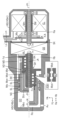
図2の部分断面図を参照して、液圧発生ユニットPSの第1の実施形態について説明する。液圧発生ユニットPS(液圧発生装置)では、電気モータMTを加圧源(「動力源」ともいう)にして、サーボ圧Pcが発生される。そして、サーボ圧Pcにより、ホイール圧Pw(=Pwf、Pwr)が調整される。
図2の部分断面図を参照して、液圧発生ユニットPSの第1の実施形態について説明する。液圧発生ユニットPS(液圧発生装置)では、電気モータMTを加圧源(「動力源」ともいう)にして、サーボ圧Pcが発生される。そして、サーボ圧Pcにより、ホイール圧Pw(=Pwf、Pwr)が調整される。
≪構成部材の形状、運動に係る方向≫
先ず、液圧発生ユニットPSを構成する要素について、形状、運動等に係る方向について規定する。液圧発生ユニットPSでは、軸ずれが発生していない状態では、電気モータMT(特に、モータシャフトSM)の回転軸線Jm、回転部材BKの回転軸線Jk、制御ピストンNCの中心軸線Jn、制御シリンダCCの中心軸線Jc、及び、中間部材BEの中心線軸Jeは、一直線上に並んでいる。軸線Jm、Jk、Jn、Jc、Jeに沿った方向(即ち、平行な方向)が「軸方向Hj」と称呼される。これに対して、軸線Jm、Jk、Jn、Jc、Jeに垂直な方向が「径方向Hk」と称呼される。従って、径方向Hkは、軸方向Hjに垂直である。
先ず、液圧発生ユニットPSを構成する要素について、形状、運動等に係る方向について規定する。液圧発生ユニットPSでは、軸ずれが発生していない状態では、電気モータMT(特に、モータシャフトSM)の回転軸線Jm、回転部材BKの回転軸線Jk、制御ピストンNCの中心軸線Jn、制御シリンダCCの中心軸線Jc、及び、中間部材BEの中心線軸Jeは、一直線上に並んでいる。軸線Jm、Jk、Jn、Jc、Jeに沿った方向(即ち、平行な方向)が「軸方向Hj」と称呼される。これに対して、軸線Jm、Jk、Jn、Jc、Jeに垂直な方向が「径方向Hk」と称呼される。従って、径方向Hkは、軸方向Hjに垂直である。
軸方向Hjに沿って運動可能な部材(NC、BE、BD等)において、制御シリンダCCの底面Mbcに近付く方向が「前進方向Ha」と称呼される。これとは逆に、制御シリンダCCの底面Mbcから遠ざかる方向が「後退方向Hb」と称呼される。従って、制御ピストンNCが前進方向Haに移動されると制御室Rcの体積は減少され、その内圧Pc(サーボ圧)は増加される。これに対して、制御ピストンNCが後退方向Hbに移動されると制御室Rcの体積は増加され、サーボ圧Pcは減少される。
電気モータMTの回転運動と直動部材BD(結果、制御ピストンNC)の直線運動との関係では、電気モータMTの正転方向Hsが、直動部材BDの前進方向Haに対応する。従って、電気モータMTの逆転方向Hgの回転運動は、直動部材BDの後退方向Hbに対応する。つまり、電気モータMTが正転方向Hsに回転すると、直動部材BDは前進方向Haに移動する。これにより、制御室Rcの体積は減少し、サーボ圧Pcは増加する。これとは逆に、電気モータMTが逆転方向Hgに回転すると、直動部材BDは後退方向Hbに移動する。これにより、制御室Rcの体積は増加し、サーボ圧Pcは減少する。
≪液圧発生ユニットPSの構成≫
液圧発生ユニットPSは、ハウジングHG、電気モータMT、回転角センサKA、減速機GS、変換機構GH、回り止め部材MD、制御ピストンNC、及び、中間部材BEにて構成される。
液圧発生ユニットPSは、ハウジングHG、電気モータMT、回転角センサKA、減速機GS、変換機構GH、回り止め部材MD、制御ピストンNC、及び、中間部材BEにて構成される。
ハウジングHGにて、液圧発生ユニットPSを構成する各部材(MT、GS等)が保持される。ハウジングHGは、構成部材が組み付けられるよう、複数に分割されている。例えば、ハウジングHGは、シリンダハウジングHGc、及び、モータハウジングHGmに分割される。モータハウジングHGmとシリンダハウジングHGcとが組付けられ、最終的にはハウジングHGとして一体化される。つまり、ハウジングHGは、シリンダハウジングHGc、及び、モータハウジングHGmの総称である。
更に、ハウジングHGは、第1コントローラEAと一体化されていてもよい。具体的には、第1コントローラEAは、マイクロプロセッサMP、及び、駆動回路DRが実装される制御基板と、それを収納するコントローラハウジング(非図示)とで構成される。そして、コントローラハウジングが、ハウジングHGに組付けられて一体化される。ハウジングHG(特に、シリンダハウジングHGc)により、減速機GS、及び、変換機構GHが保持される。また、ハウジングHG(特に、モータハウジングHGm)により、電気モータMTが保持される。
ハウジングHG(特に、シリンダハウジングHGc)には、制御シリンダCC(「シリンダ」に相当)が形成される。制御シリンダCCには、制御ピストンNC(「ピストン」に相当)が挿入される。そして、制御シリンダCCと制御ピストンNCとによって、制御室Rc(液圧室)が形成される。制御シリンダCC(特に、制御室Rc)には、吐出部Auが設けられる。吐出部Auには、サーボ路HU、及び、後輪連絡路HSrが接続される。即ち、制御室Rcは、サーボ室Ru、及び、後輪ホイールシリンダCWrに接続される。これにより、サーボ圧Pcが、サーボ室Ru、及び、後輪ホイールシリンダCWrに供給(出力)される。
電気モータMTは、サーボ圧Pc(制御シリンダCC内の液圧)を発生するための動力源(加圧源)である。ここで、「動力」は、液圧発生ユニットPSにおける可動部材(BK、BD等)を動かすために必要なエネルギのことである。例えば、動力は、物理量として、単位時間当りのエネルギ(「仕事率」ともいう)として規定される。電気モータMTから、回転動力Tm(「第1回転動力」ともいう)が出力される。電気モータMTの回転動力Tmは、電気モータMTの軸トルクに、電気モータMT(特に、モータシャフトSM)の回転速度を乗じたものである。なお、直動部材BD(後述)の直線動力Fnは、直動部材BDの推力(軸方向Hjに作用する力)に直動部材BDの直線速度(軸方向Hjの速度)を乗じたものである。
電気モータMTとして、3相ブラシレスモータが採用される。電気モータMTは、モータハウジングHGm内に取り付けられる。電気モータMTには、モータコイルCL、モータシャフトSM、及び、回転角センサKAが含まれる。モータコイルCL(単に、「コイル(巻線)」ともいう)は、モータハウジングHGm内に固定される。モータコイルCLは「固定子」とも称呼される。モータコイルCLには、モータ線Lmが接続される。モータコイルCLには、モータ線Lmを介して、第1コントローラEA(特に、駆動回路DR)から電力が供給される。
モータシャフトSM(単に、「シャフト」ともいう)は、モータハウジングHGm内に固定されたベアリングBBにより、モータハウジングHGm(つまり、モータコイルCL)に対して回転可能に支持される。電気モータMTのシャフトSMの外周には、モータ磁石Mm(永久磁石)が固定されている。例えば、モータ磁石Mmは、接着等によってモータシャフトSMに貼り付けられている。モータシャフトSMは「回転子」とも称呼される。
3相ブラシレスモータMTでは、回転子SMの磁極位置(即ち、固定子CLに対する回転角)が検出されて、モータコイルCLに流される電流Im(モータ電流)が切り替えられる。ここで、モータ電流Imは、U相、V相、W相に流される電流の総称である。U相、V相、W相に係る3相のモータ電流Imは、モータシャフトSMの回転位置Ka(「回転角」ともいう)に基づいて切り替えられる。第1コントローラEAでは、回転角Kaに応じて、駆動回路DR(インバータ回路)のスイッチング素子が駆動される。これにより、モータコイルCLに流されるモータ電流Imが切り替えられ、電気モータMTが回転駆動される。そして、回転動力Tmが、電気モータMTから減速機GSに出力される。
回転角Kaを検出するよう、電気モータMT(ブラシレスモータ)には回転角センサKAが設けられる。回転角センサKAは、センサディスクDs、センサ磁石Ms、センサ基板Kb、及び、センサ線Lsにて構成される。センサディスクDsは、モータシャフトSMと一体となって回転するよう、モータシャフトSMに固定される。センサディスクDsには、センサ磁石Msが設けられる。センサ基板Kbは、モータハウジングHGmに固定される。センサ基板Kbには、モータシャフトSMが貫通するように孔があけられている。孔の周辺部には、モータシャフトSM(即ち、センサ磁石Ms)が回転する際に生じる磁界の変化を検出するよう、磁界検出素子を用いた検出部が設けられる。磁界検出素子により検出された信号が、センサ線Lsによって第1コントローラEA(特に、マイクロプロセッサMP)に伝達される。
減速機GSにより、電気モータMTから出力された第1回転動力Tmが減速され、第2回転動力Tnが出力される。具体的には、減速機GSの入力軸とモータシャフトSMとが固定される。また、減速機GSの出力軸と変換機構GHの回転部材BKとが固定される。減速機GSでは、電気モータMTから入力される速度が減少されるとともに、電気モータMTから入力されるトルクが増加される。そして、第2回転動力Tnが、減速機GSから変換機構GHに出力される。
例えば、減速機GSとして、遊星歯車機構が採用される。「遊星歯車機構」では、太陽歯車を中心として、複数の遊星歯車が自転しながら公転する歯車機構である。減速機GSは、太陽歯車、遊星歯車、内歯車、及び、遊星キャリヤにて構成される。遊星歯車機構では、遊星キャリヤにより、遊星歯車が支持され、公転運動が取り出される。例えば、減速機GSでは、内歯車(「インナギヤ」ともいう)がシリンダハウジングHGcに固定される。太陽歯車(「サンギヤ」ともいう)がモータシャフトSMに固定され、太陽歯車に電気モータMTからの第1回転動力Tmが入力される。そして、減速機GSの遊星キャリヤが回転部材BKに固定され、遊星キャリヤから変換機構GHに第2回転動力Tnが出力される。
変換機構GHは、回転運動をする回転部材BK、及び、直線運動をする直動部材BDにて構成される。変換機構GHでは、減速機GSから出力される第2回転動力Tnが、回転部材BKに入力される。そして、回転部材BKに入力された第2回転動力Tnが、直動部材BDの直線動力Fnに変換される。変換機構GHは、「回転・直動変換機構」とも称呼される。
例えば、変換機構GHとして、「ボールねじ」が採用される。具体的には、変換機構GHでは、シャフト部材である回転部材BKが、減速機GSの出力軸に固定される。回転部材BKは、円筒形状を有する直動部材BDに挿入される。回転部材BKの外周面Mokにはボールねじ溝Mzkが形成される。同様に、直動部材BDの内周面Midにもボールねじ溝Mzdが形成される。ボールねじ溝Mzk、Mzdには、複数のボールBL(鋼球)がはめ込まれている(以上、吹出し部XGHを参照)。
変換機構GHでは、外周面にねじ溝を有する部材が「内側部材」と称呼される。また、内周面にねじ溝を有する部材が「外側部材」と称呼される。そして、外側部材が内側部材を覆うように配置され、内側部材のねじ溝と外側部材のねじ溝とがかみ合わされる。詳細には、ボールねじ機構では、複数のボールBLを介して、2つのねじ溝がかみ合わされる。
変換機構GHとして採用されるボールねじ機構では、ボールねじシャフト(内側部材であり、「シャフト部材」ともいう)が回転部材BKにされ、ボールねじナット(外側部材であり、「ナット部材」ともいう)が直動部材BDにされる。該構成では、回転部材BK(内側部材)の外周面Mokにねじ溝Mzkが形成され、直動部材BD(外側部材)の内周面Midにねじ溝Mzdが形成される。そして、ボールBLを介して、外周溝Mzkと内周溝Mzdとがかみ合わされる。
直動部材BDには、制御シリンダCC(特に、制御室Rc)から離れた側の端部に、フランジ部Fdが設けられる。フランジ部Fdは、円筒形状の直動部材BDの端部が、つば形状に、径方向Hkに延ばされている。フランジ部Fdには切り欠きが形成されている。該切り欠きが、回り止め部材MDに嵌合される。
回り止め部材MDは、シリンダハウジングHGcに固定されている。例えば、回り止め部材MDには、細長い棒形状の部材(例えば、ピン部材)が用いられる。ハウジングHGには、直動部材BDの外側(即ち、直動部材BDに対して回転軸線Jkから離れている側)に、複数の孔が設けられる。複数の孔は、回転軸線Jkまわりに均等な間隔であけられている。複数の孔の夫々には、回り止め部材MDが挿入されて、固定される。直動部材BDのフランジ部Fdには、半円形状の切り欠きが設けられる。そして、該切り欠きと回り止め部材MDとがかみ合わされることにより、直動部材BDでは、回転軸線Jkまわりの回転運動が阻止される。これにより、回転部材BKが回転駆動されると、直動部材BDは、軸方向Hj(前進方向Ha又は後退方向Hb)に沿って移動する。
制御ピストンNCは、シリンダハウジングHGcに形成された制御シリンダCCに挿入される。詳細には、制御ピストンNCは、底部Btn(「第1底部」ともいう)と円筒部Enn(「第1円筒部」ともいう)とで構成される。即ち、制御ピストンNCは底部Btnを持つ円筒形状(カップ形状)を有している。制御シリンダCCに挿入された制御ピストンNC(特に、第1底部Btn)により、制御シリンダCCの内部には制御室Rc(液圧室)が形成される。
制御ピストンNCの外周面Monと制御シリンダCCの内周面Micとは、2つのシール部材SLにて封止される。2つのシール部材SLは、制御シリンダCCの内周面Micに形成されたシール溝にはめ込まれる。2つのシール溝の間にて、シリンダハウジングHGcには、制御シリンダCCに貫通する孔(非図示であり、「ハウジング孔」ともいう)が設けられる。ハウジング孔は、補給路HHを介して、マスタリザーバRVに接続される。制御ピストンNCには、ハウジング孔と制御室Rcとを接続するよう、外周面Monから底部Btnに貫通する孔(非図示であり、「ピストン孔」ともいう)が設けられる。
中間部材BEが、軸方向Hjにおいて、直動部材BDと制御ピストンNCとの間に設けられる。中間部材BEは、直動部材BDと制御ピストンNCとの間で動力を伝達する。直動部材BDからの直線動力Fnは、中間部材BEを介して、制御ピストンNCに伝達される。これにより、直動部材BD、中間部材BE、及び、制御ピストンNCは一体となって、前進方向Haに移動することができる。なお、直動部材BD、中間部材BE、及び、制御ピストンNCが後退方向Hbに戻る際にも一体で移動できるよう、直動部材BDと制御ピストンNCとは、抜け止め部材NDにて留められている。
制御ピストンNCは、制御シリンダCCに対して、シール部材SLにてシールされているが、軸ずれ(特に、直線動力Fnの方向と制御ピストンNCの移動方向とのずれ)が生じると、制御ピストンNCの外周面Monとシール部材SLとの接触が均一ではなくなる。このことに起因して、シール性の低下、シール部材SLの偏摩耗等が生じることがある。制御ピストンNC等の軸ずれの影響(即ち、シール性の低下、シール部材SLの偏摩耗等)が抑制されるよう、直動部材BDから制御ピストンNCへの動力伝達経路に、中間部材BEが設けられる。
中間部材BEは、底部Bte(「第2底部」ともいう)と円筒部Ene(「第2円筒部」ともいう)とで構成される。制御ピストンNCと同様に、中間部材BEは、第2底部Bteを持つ円筒形状(即ち、カップ形状)を有している。そして、中間部材BEは、制御ピストンNCの内側(内部)に収められる。即ち、制御ピストンNCと中間部材BEとは、入子の状態になっている。該構造が「入子構造」と称呼される。入子構造では、外側の制御ピストンNCがシール部材SLと摺動することにより制御室Rcの封止が行われ、内側の中間部材BEにより軸ずれの影響が補償される。
≪サーボ圧Pcの調整≫
制動制御装置SCでは、液圧発生ユニットPSの出力であるサーボ圧Pcにより、ホイール圧Pwが調整される。液圧発生ユニットPSでは、電気モータMTの回転動力Tm(即ち、軸トルク)が、変換機構GHにより、直動部材BD(結果、制御ピストンNC)の直線動力Fn(即ち、推力)に変換される。そして、直線動力Fnによって制御ピストンNCが移動されることにより、サーボ圧Pcが発生され、調整される。なお、液圧発生ユニットPSには、サーボ圧Pcを検出するために、サーボ圧センサPCが設けられる。
制動制御装置SCでは、液圧発生ユニットPSの出力であるサーボ圧Pcにより、ホイール圧Pwが調整される。液圧発生ユニットPSでは、電気モータMTの回転動力Tm(即ち、軸トルク)が、変換機構GHにより、直動部材BD(結果、制御ピストンNC)の直線動力Fn(即ち、推力)に変換される。そして、直線動力Fnによって制御ピストンNCが移動されることにより、サーボ圧Pcが発生され、調整される。なお、液圧発生ユニットPSには、サーボ圧Pcを検出するために、サーボ圧センサPCが設けられる。
変換機構GHでは、回転運動から直線運動への変換と、直線運動から回転運動への変換との両方が可能である。変換機構GHの作動において、前者が「正作動」と称呼され、後者が「逆作動」と称呼される。このため、制御ピストンNCの移動は、電気モータMTから出力されるトルク(「正作動トルクQmt」ともいう)と、サーボ圧Pcにより電気モータMTに入力されるトルク(「逆作動トルクQpc」ともいう)との大小関係によって定まる。以下、サーボ圧Pcの調整(増減)について説明する。
≪サーボ圧Pcの増加≫
図2において、回転軸線Jkの上部には、液圧発生ユニットPSがサーボ圧Pcを発生していない状態が図示されている。該状態では、制御室Rcは、ハウジング孔、及び、ピストン孔を介して、マスタリザーバRVに接続されていて、サーボ圧Pcは「0(大気圧)」である。該状態での直動部材BD、制御ピストンNC等の位置が「初期位置」と称呼される。初期位置では、制御ピストンNCは後退方向Hbに最大限に変位し、制御室Rcの体積は最大になっている。
図2において、回転軸線Jkの上部には、液圧発生ユニットPSがサーボ圧Pcを発生していない状態が図示されている。該状態では、制御室Rcは、ハウジング孔、及び、ピストン孔を介して、マスタリザーバRVに接続されていて、サーボ圧Pcは「0(大気圧)」である。該状態での直動部材BD、制御ピストンNC等の位置が「初期位置」と称呼される。初期位置では、制御ピストンNCは後退方向Hbに最大限に変位し、制御室Rcの体積は最大になっている。
上述したように、制御ピストンNC、及び、中間部材BEは、有底円筒形状(カップ形状)を有し、それらが入子状態にされるので、中間部材BEは、制御ピストンNCの内部に収納されている。更に、制御ピストンNCが初期位置にある場合には、中間部材BEの内部に回転部材BKが入り込んでいる。該構造によって、液圧発生ユニットPSでは、軸方向Hjのサイズが小型化される。
制動要求値(制動力に係る要求を表示する状態量であり、例えば、制動操作部材BPの操作変位Sp)が増加されると、目標圧Ptが「0」から増加される。目標圧Ptは、サーボ圧Pc(実際値)に対応する目標値である。目標圧Ptは、制動要求値の増加に伴って増加される。目標圧Ptの増加に伴い、正作動トルクQmtが逆作動トルクQpcよりも大きくなり、電気モータMTは正転方向Hsに回転する。つまり、電気モータMTは、正転方向Hsに回転動力Tmを発生する。回転動力Tmは、減速機GSを介して、変換機構GHに伝達され、直動部材BDの直線動力Fnとして出力される。そして、直動部材BDにより中間部材BEが押圧され、中間部材BEにより制御ピストンNCが押圧される。これにより、制御ピストンNCが前進方向Ha(制御室Rcの体積が減少する方向)に移動される。中間部材BEの視点では、回転部材BKが、中間部材BEの内部から徐々に出ていく。
該移動により、制御ピストンNCにあけられたピストン孔は制御室Rc内に移動するので、先ず、制御室RcとマスタリザーバRVとの連通が遮断される。制御ピストンNCが、更に、前進方向Haに移動されると、サーボ圧Pc(制御室Rcの内圧)が「0(大気圧)」から増加される。制御シリンダCCの制御室Rcから、サーボ圧Pcに加圧された制動液BFが、サーボ室Ru、及び、後輪ホイールシリンダCWrに出力(圧送)される。
≪サーボ圧Pcの保持≫
制動要求値が一定になると、目標圧Ptは保持される。正作動トルクQmtと逆作動トルクQpcとは等しくなり、電気モータMTの回転は停止する(即ち、電気モータMTの回転速度が「0」になる)。制御ピストンNCの移動が停止されることにより、サーボ圧Pcは一定で維持される(図2の回転軸線Jkの下部を参照)。
制動要求値が一定になると、目標圧Ptは保持される。正作動トルクQmtと逆作動トルクQpcとは等しくなり、電気モータMTの回転は停止する(即ち、電気モータMTの回転速度が「0」になる)。制御ピストンNCの移動が停止されることにより、サーボ圧Pcは一定で維持される(図2の回転軸線Jkの下部を参照)。
≪サーボ圧Pcの減少≫
制動要求値が減少されると、目標圧Ptが減少される。これにより、電気モータMTの回転動力Tmは減少される。サーボ圧Pcによる逆作動トルクQpcが、電気モータMTによる正作動トルクQmtよりも大きくなり、電気モータMTは逆転方向Hgに回転する。制御ピストンNCは、後退方向Hbに移動され、制御室Rcの体積は増加される。サーボ室Ru、及び、後輪ホイールシリンダCWrに移動されていた制動液BFは、制御室Rcに向けて戻されるため、サーボ圧Pcは減少される。中間部材BEと回転部材BKとの位置的な関係では、回転部材BKは、中間部材BEの内部に徐々に入り込んでいく。
制動要求値が減少されると、目標圧Ptが減少される。これにより、電気モータMTの回転動力Tmは減少される。サーボ圧Pcによる逆作動トルクQpcが、電気モータMTによる正作動トルクQmtよりも大きくなり、電気モータMTは逆転方向Hgに回転する。制御ピストンNCは、後退方向Hbに移動され、制御室Rcの体積は増加される。サーボ室Ru、及び、後輪ホイールシリンダCWrに移動されていた制動液BFは、制御室Rcに向けて戻されるため、サーボ圧Pcは減少される。中間部材BEと回転部材BKとの位置的な関係では、回転部材BKは、中間部材BEの内部に徐々に入り込んでいく。
<中間部材BEによる軸ずれの影響補償>
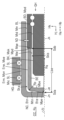
図3の部分断面図を参照して、中間部材BEによる軸ずれの影響抑制について説明する。ここで、軸ずれに起因する影響が抑制されることが「軸ずれ補償」と称呼される。図3には、軸ずれは発生しておらず、回転部材BKの回転軸線Jk、中間部材BEの中心軸線Je、制御ピストンNCの中心軸線Jn、及び、制御シリンダCCの中心軸線Jcが、一直線上に並んでいる状況が示されている。
図3の部分断面図を参照して、中間部材BEによる軸ずれの影響抑制について説明する。ここで、軸ずれに起因する影響が抑制されることが「軸ずれ補償」と称呼される。図3には、軸ずれは発生しておらず、回転部材BKの回転軸線Jk、中間部材BEの中心軸線Je、制御ピストンNCの中心軸線Jn、及び、制御シリンダCCの中心軸線Jcが、一直線上に並んでいる状況が示されている。
≪軸ずれ≫
初めに、軸ずれについて説明する。動力伝達では、軸線Jk、Jn、Jcは一直線上に存在することが望ましい。しかしながら、変換機構GH、制御ピストンNC、制御シリンダCC等は個別の部材であるため、それらの軸線Jk、Jn、Jcが一直線上から外れて、ずれることがある。軸線Jk、Jn、Jcのずれが「軸ずれ」と称呼される。軸ずれは、軸線間の偏芯(芯ずれ)であり、「ミスアライメント」とも称呼される。
初めに、軸ずれについて説明する。動力伝達では、軸線Jk、Jn、Jcは一直線上に存在することが望ましい。しかしながら、変換機構GH、制御ピストンNC、制御シリンダCC等は個別の部材であるため、それらの軸線Jk、Jn、Jcが一直線上から外れて、ずれることがある。軸線Jk、Jn、Jcのずれが「軸ずれ」と称呼される。軸ずれは、軸線間の偏芯(芯ずれ)であり、「ミスアライメント」とも称呼される。
例えば、2つ軸線が交わっているが、これらが角度を有している場合(即ち、平行度不足)がある。このような軸ずれが、「偏角ずれ(又は、偏角誤差)」と称呼される。また、2つ軸線が平行にずれている場合がある。このような軸ずれが、「平行ずれ(又は、平行誤差)」と称呼される。通常、軸ずれは、偏角ずれと平行ずれとが組み合わさって発生する。
軸ずれ(芯ずれ)が発生すると、上述したように、制御ピストンNCの外周面Monとシール部材SLとの接触が不均一になるため、シール部材SLのシール性の低下、偏摩耗の発生が懸念される。また、変換機構GHにおいても負荷が不均一になるので、ボール部材BL、ねじ溝Mzk、Mzd等の偏摩耗が生じ得る。液圧発生ユニットPSには、軸ずれ補償のために、中間部材BEが設けられる。
≪中間部材BE等の構成≫
次に、変換機構GH、制御ピストンNC、及び、中間部材BEの詳細な構成について説明する。変換機構GHは、回転部材BK、及び、直動部材BDにて構成される。回転部材BKは、ハウジングHGに対して、並進運動(軸方向Hjの直進運動)は拘束されるが、回転運動は可能な状態で保持される。一方、直動部材BDは、ハウジングHGに対して、回転運動は拘束されるが、並進運動は可能な状態で保持される。これにより、変換機構GHは、回転部材BKに入力される回転動力Tmを直動部材BDの直線動力Fnとして出力する。ここで、変換機構GHでは、直動部材BDが回転部材BKを覆うように配置されている。例えば、変換機構GHとして、ボールねじ機構が採用される構成では、回転部材BKはボールねじシャフトであり、直動部材BDはボールねじナットである。
次に、変換機構GH、制御ピストンNC、及び、中間部材BEの詳細な構成について説明する。変換機構GHは、回転部材BK、及び、直動部材BDにて構成される。回転部材BKは、ハウジングHGに対して、並進運動(軸方向Hjの直進運動)は拘束されるが、回転運動は可能な状態で保持される。一方、直動部材BDは、ハウジングHGに対して、回転運動は拘束されるが、並進運動は可能な状態で保持される。これにより、変換機構GHは、回転部材BKに入力される回転動力Tmを直動部材BDの直線動力Fnとして出力する。ここで、変換機構GHでは、直動部材BDが回転部材BKを覆うように配置されている。例えば、変換機構GHとして、ボールねじ機構が採用される構成では、回転部材BKはボールねじシャフトであり、直動部材BDはボールねじナットである。
直動部材BDの端部(詳細には、制御シリンダCCの底面Mbc、又は、制御ピストンNCの底部Btnから離れた側の端部)には、フランジ部Fdが設けられる。フランジ部Fdの外周部には切り欠きが形成される。該切り欠きは回り止め部材MDにかみ合わされる。回り止め部材MDはハウジングHGに固定されている。回り止め部材MDにより、ハウジングHGに対する直動部材BDの回転運動が阻止されるので、回転部材BKの回転運動は、直動部材BDの直線運動に変換され得る。
制御ピストンNCがハウジングHGに形成された制御シリンダCCに挿入される。制御ピストンNCは、有底円筒形状(カップ形状)であり、第1底部Btnと第1円筒部Ennとで構成される。制御シリンダCCの内周面Micには、2つのシール溝が形成される。シール溝の夫々には、シール部材SLがはめ込まれる。円筒部Ennの外周面Monと制御シリンダCCの内周面Micとが、シール部材SLにより封止される。制御ピストンNC(特に、底部Btn)により、制御シリンダCC内に制御室Rc(液圧室)が形成される。なお、第1底部Btnの内側底面Mtnには、制御ピストンNCの中心軸線Jn(即ち、第1円筒部Ennの中心軸線)に対して垂直な平面が形成される。
制御ピストンNCの円筒部Ennの内周面Minには円環状の溝が形成される。また、直動部材BDの外周面Modにも円環状の溝が形成される。これらの溝には、抜け止め部材ND(例えば、スナップリング)がはめ込まれる。抜け止め部材NDにより、制御ピストンNCと直動部材BDとが完全に分離しないように、制御ピストンNCと直動部材BDとの相対的な変位が制限される。なお、抜け止め部材NDは、軸方向Hj、及び、径方向Hkにおいて、円環状の溝に対してガタ(隙間)を有している。このため、制御ピストンNCと直動部材BDとは、軸方向Hj、及び、径方向Hkの何れの方向においても、ガタの範囲内で相互に変位することが可能である。
中間部材BEが、制御ピストンNCと直動部材BDとの間に設けられる。中間部材BEは、制御ピストンNCと同様に、有底円筒形状(カップ形状)であり、第2底部Bteと第2円筒部Eneとで構成される。入子構造(即ち、中間部材BEが制御ピストンNCの内部に配置される構造)では、制御ピストンNCの底部Btn(第1底部)と中間部材BEの底部Bte(第2底部)とは、摺動可能な状態で接触している。ここで、「摺動」は、2つの部材が接触した状態で滑りながら動く動作である。
詳細には、中間部材BEの外側底面Mpe(「押圧面」ともいう)と、制御ピストンNCの内側底面Mtn(「受圧面」ともいう)との間に滑りが発生可能である。中間部材BEの押圧面Mpeには、半径Rqの球面形状の凸部が形成される。また、中間部材BEにおいて、押圧面Mpeと円筒部Eneの外周面Moeとが接続される部位(「角部」ともいう)には、半径Rpの角丸(「角R」ともいう)が形成される。即ち、中間部材BEの底部Bteの角部には、丸みが設けられている。ここで、凸球面の半径Rqは、角丸の半径Rpに対して格段に大きい。中間部材BEの押圧面Mpe(外側底面)と制御ピストンNCの受圧面Mtn(内側底面)とが接触する部位が「第1摺動部Sda」と称呼される。
中間部材BEの円筒部Eneの端面Mqe(「中間端面」ともいう)は、直動部材BDの端面Mpd(「直動端面」ともいう)と摺動可能な状態で接触している。例えば、中間端面Mqeは、中間部材BEの中心軸線Je(即ち、第2円筒部Eneの中心軸線)に対して垂直な平面である。また、直動端面Mpdは、回転軸線Jkに対して垂直な平面である。従って、直動端面Mpdと中間端面Mqeとは、軸方向Hjに垂直であり、径方向Hkに平行な平面で接触する。ここで、中間部材BEの中間端面Mqeと直動部材BDの直動端面Mpdとが接触する部位が「第2摺動部Sdb」と称呼される。
変換機構GH、制御ピストンNC、及び、中間部材BEの構成をまとめると、以下の通りである。中間部材BEは、制御ピストンNCの内側に収まる。中間部材BEは、直動部材BD(特に、直動端面Mpd)と制御ピストンNC(特に、受圧面Mtn)との間に位置する。サーボ圧Pcの増加では、直動端面Mpd(平面)により中間端面Mqe(平面)が前進方向Haに押されることで、押圧面Mpe(凸面)により受圧面Mtn(平面)が前進方向Haに押される。これにより、制御ピストンNC、中間部材BE、及び、直動部材BDは、前進方向Haに移動する。これとは逆に、サーボ圧Pcの減少では、受圧面Mtnにより押圧面Mpeが後退方向Hbに押されることで、中間端面Mqeにより直動端面Mpdが後退方向Hbに押される。これにより、制御ピストンNC、中間部材BE、及び、直動部材BDは、後退方向Hbに移動する。ここで、中間部材BEは、制御ピストンNC、及び、直動部材BDとの摺動が可能な2つの部位(即ち、第1、第2摺動部Sda、Sdb)を有している。
中間部材BEの円筒部Eneの内部には、回転部材BKが入り込むことができる。換言すれば、中間部材BEの円筒部Eneは、制御ピストンNCの円筒部Enn(特に、内周面Min)と回転部材BK(特に、外周面Mok)との隙間に入り込むことができる。直動部材BDの移動に応じて、中間部材BE、及び、制御ピストンNCは移動するが、少なくとも初期位置(「Pc=0」に対応する位置)においては、中間部材BEの内部に回転部材BKの一部が収納される。液圧発生ユニットPSでは、「制御ピストンNC、及び、中間部材BEにカップ形状が採用され、それらが入子構造にされていること」、及び、「中間部材BEの内側に回転部材BKが収められること」により、軸方向Hjの寸法短縮が図られる。
≪軸ずれ補償≫
最後に、軸ずれ補償について説明する。軸ずれの影響は、「動力伝達部材(BD、BE、NC等)の間で、径方向Hkにおいて滑りが許容されること」、及び、「制御ピストンNCと中間部材BEとの接触において中間部材BEが回転できること」により補償される。動力伝達部材は、径方向Hkにおいて、相互に隙間Ska、Skbを有している。直動部材BD、中間部材BE、及び、直動部材BDは、該隙間Ska、Skbにより、部材間で滑りながら移動することができる。
最後に、軸ずれ補償について説明する。軸ずれの影響は、「動力伝達部材(BD、BE、NC等)の間で、径方向Hkにおいて滑りが許容されること」、及び、「制御ピストンNCと中間部材BEとの接触において中間部材BEが回転できること」により補償される。動力伝達部材は、径方向Hkにおいて、相互に隙間Ska、Skbを有している。直動部材BD、中間部材BE、及び、直動部材BDは、該隙間Ska、Skbにより、部材間で滑りながら移動することができる。
第1摺動部Sdaでは、制御ピストンNCの受圧面Mtn(例えば、第1円筒部Ennの中心軸線Jnに垂直な平面)と中間部材BEの押圧面Mpe(例えば、凸面)とが接する。受圧面Mtnと押圧面Mpeとは、「制御ピストンNCの内周面Minと中間部材BEの外周面Moeとの隙間Skaの範囲内」、又は、「中間部材BEの内周面Mieと回転部材BKの外周面Mokとの隙間Skbの範囲内」で径方向Hkに相互変位することが可能である。加えて、押圧面Mpeは凸面(例えば、球面)であるため、受圧面Mtnと押圧面Mpeとの接触部を中心にして、相互に回転変位することができる。該回転運動が「揺動」と称呼される。第1摺動部Sdaでの揺動と滑り(摺動)により、制御ピストンNC等の軸ずれ(偏角ずれ、及び、平行ずれ)の影響が抑制される。なお、受圧面Mtnと押圧面Mpeとの回転変位(即ち、揺動の程度)が大きくなると、受圧面Mtnが中間部材BEの角部に接触する。該角部には丸み(角丸)が設けられているため、偏角ずれが過大になっても、受圧面Mtnと押圧面Mpeと接触面圧が抑制される。
第2摺動部Sdbでは、直動部材BDの直動端面Mpd(例えば、回転部材BKの回転軸線Jkに垂直な平面)と中間部材BEの中間端面Mqe(例えば、第2円筒部Eneの中心軸線Jeに垂直な平面)とが接する。該接触では、直動端面Mpdと中間端面Mqeとは、相互に摺動可能である。従って、直動端面Mpdと中間端面Mqeとは、「制御ピストンNCの内周面Minと中間部材BEの外周面Moeとの隙間Skaの範囲内」、又は、「中間部材BEの内周面Mieと回転部材BKの外周面Mokとの隙間Skbの範囲内」で径方向Hkに相互変位することが可能である。
制御ピストンNCは、シール部材SLによりハウジングHGに保持されている。また、変換機構GH(特に、直動部材BD)がベアリングによりハウジングHGに保持されている。中間部材BEは、ハウジングHGに直接的には保持されてはおらず、フローティングジョイントとしての役割を果たす。具体的には、中間部材BEは、制御ピストンNC、及び、直動部材BDの両方の部材に対して、径方向Hkに摺動し、平行移動することができる。これにより、平行ずれの影響が好適に抑制される。また、中間部材BEは、制御ピストンNCに対して揺動することができるので、偏角ずれの影響が適切に抑制される。加えて、第2摺動部Sdbが存在することにより、第1摺動部Sdaでの摺動及び揺動が妨げられない。即ち、摺動・揺動が生じ易くされるため、偏角ずれの補償効果が向上される。液圧発生ユニットPSでは、中間部材BEにより、2つの摺動部Sda、Sdbが設けられることで、平行ずれの影響が抑制されるだけでなく、偏角ずれの影響補償が好適に行われる。
第1摺動部Sdaと第2摺動部Sdbとの間の距離Lbe(即ち、中間部材BEの軸方向Hjの長さ)は、2つのシール部材SLの間隔よりも長く設定されることが望ましい。これは、第1、第2摺動部Sda、Sdbが或る程度、離れている方が、軸ずれ補償の効果が高いことに基づく。
<液圧発生ユニットPSの第2の実施形態>
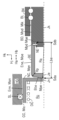
図4の部分断面図を参照して、液圧発生ユニットPSの第2の実施形態について説明する。第1の実施形態では、回転部材BKが内側部材であり、直動部材BDが外側部材であった。これとは逆に、第2の実施形態では、回転部材BKが外側部材であり、直動部材BDが内側部材である。以下、第1の実施形態との相違点を中心に説明する。なお、第2の実施形態でも、構成部材の形状、運動に係る方向は、第1の実施形態と同じである。
図4の部分断面図を参照して、液圧発生ユニットPSの第2の実施形態について説明する。第1の実施形態では、回転部材BKが内側部材であり、直動部材BDが外側部材であった。これとは逆に、第2の実施形態では、回転部材BKが外側部材であり、直動部材BDが内側部材である。以下、第1の実施形態との相違点を中心に説明する。なお、第2の実施形態でも、構成部材の形状、運動に係る方向は、第1の実施形態と同じである。
第2の実施形態では、制御ピストンNCは、特許文献3(特開2012-214068号)と同様の構成である。制御ピストンNCは、制御シリンダCCに挿入され、シール部材SLにて封止される。制御ピストンNCを後退方向Hbに押圧するよう、制御室Rcには、戻しばねDCが設けられている。第2の実施形態でも、中間部材BEは、直動部材BDと制御ピストンNCとの間に位置する。中間部材BEは、底部Bteと円筒部Eneとを有する、所謂、有底円筒形状(カップ形状)をしている。中間部材BEは、直動部材BDから離れないように、抜け止め部材NEで留められている。直動部材BDと中間部材BEとは、抜け止め部材NEのガタの範囲で、軸方向Hj、及び、径方向Hkに相対変位することができる。
中間部材BEの押圧面Mpe(外側底面)には、半径Rqの球面形状の凸部が形成される。また、中間部材BEにおいて、押圧面Mpeの角部(底面と側面との接続部)には、半径Rpの角丸(角R)が形成される。中間部材BEは、凸球面の押圧面Mpe(中間部材BEの一方側端面)にて、摺動及び揺動が可能な状態で、制御ピストンNCの底面Mqn(受圧面であり、例えば、中心軸線Jnに垂直な平面)を押圧する。押圧面Mpeと受圧面Mqnとが接触する部位が、第2の実施形態における第1摺動部Sdaである。
また、中間部材BEの端面Mqe(中間端面であり、中間部材BEの他方側端面)は、直動部材BDの端面Mpd(直動端面)により、摺動可能な状態で押圧される。直動端面Mpdと中間端面Mqeとが接触する部位が、第2の実施形態における第2摺動部Sdbである。第1の実施形態と同様に、第2の実施形態でも、中間部材BEは、制御ピストンNC、及び、直動部材BDとの摺動が可能な2つの部位(即ち、第1、第2摺動部Sda、Sdb)を有している。これにより、液圧発生ユニットPSでは、平行ずれの影響が抑制されるとともに、偏角ずれの影響補償の効果が向上される。
液圧発生ユニットPSの軸方向Hjの寸法を低減するために、第2の実施形態でも、第1の実施形態と同様に、有底円筒形状の制御ピストンNCが採用されてもよい。該構成では、制御ピストンNCの内側に中間部材BEが配置され、上記の入子構造が形成され得る。しかしながら、第2の実施形態では、中間部材BEの内側に回転部材BKを侵入させることができない。このため、軸方向寸法(軸長)の観点では、第1の実施形態の方が有利である。
<液圧発生ユニットPSの他の実施形態等>
以下、液圧発生ユニットPSの他の実施形態について説明する。他の実施形態でも、液圧発生ユニットPSは、上記同様の効果(軸ずれ補償等)を奏する。
以下、液圧発生ユニットPSの他の実施形態について説明する。他の実施形態でも、液圧発生ユニットPSは、上記同様の効果(軸ずれ補償等)を奏する。
上述した液圧発生ユニットPSの実施形態では、変換機構GHとしてボールねじが採用された。これに代えて、変換機構GHには、滑りねじ(例えば、台形ねじ)が採用されてもよい。滑りねじ機構が採用される構成では、内側部材には、ねじ溝として、おねじが形成される。また、外側部材には、ねじ溝として、めねじが形成される。そして、おねじとめねじとが直接かみ合わされる。滑りねじが採用される変換機構GHでも逆作動は生じる。
上述した液圧発生ユニットPSの実施形態では、軸線Jmと軸線Jc、Jn、Jkとが一直線上に並ぶ構成が採用された。該構成は、軸線Jmと軸線Jc等とが同軸上に存在するため「同軸構成(或いは、1軸構成)」と称呼される。同軸構成では、減速機GSにおいて、入力軸の回転軸線と出力軸の回転軸線とが同軸上にあるもの(例えば、遊星歯車機構)が用いられる。該構成に代えて、軸線Jmと軸線Jc、Jn、Jkとが別軸上に存在する「別軸構成(或いは、2軸構成)」が採用されてもよい。別軸構成では、減速機GSにおいて、入力軸の回転軸線と出力軸の回転軸線とが異なるもの(例えば、歯車列)が用いられる。別軸構成では、軸線Jmと、軸線Jc、Jn、Jkとは、別軸であるが、平行に配置される。なお、別軸構成でも、軸線Jc、Jn、Jkは一直線上に存在する。
上述した制動制御装置SCは、前輪WHfに回生装置KGが備えられ、回生協調制御が実行される車両に適用された。回生協調制御が実行される車両では、回生装置KGは、前輪WHf、及び、後輪WHrのうちの少なくとも1つに備えられていればよい。また、制動制御装置SCは、回生装置KGが省力され、回生協調制御が実行されない車両にも適用され得る。つまり、制動制御装置SCは、回生協調制御の有無とは無関係に、各種車両に適用され得る。
上述した制動制御装置SCの構成例では、シングル型のマスタシリンダCMが採用された。制動制御装置SCでは、タンデム型のマスタシリンダCMが採用されてもよい。該構成では、CMの内部に、2つのマスタ室Rmが形成される。そして、液圧発生ユニットPSからサーボ圧Pcがサーボ室Ruに供給され、マスタ室RmからホイールシリンダCWに、ホイール圧Pwが供給される。該構成では、制動制御装置SCには、2系統の制動系統として、前後型だけでなく、ダイアゴナル型(「X型」ともいう)のものが採用されてもよい。ダイアゴナル型の制動制御装置SCでは、2つのマスタ室Rmうちの一方が、右前輪ホイールシリンダ、及び、左後輪ホイールシリンダに接続される。また、2つのマスタ室Rmうちの他方が、左前輪ホイールシリンダ、及び、右後輪ホイールシリンダに接続される。
上述した制動制御装置SCの構成例では、第1制動ユニットSAにおいて、供給圧PmがマスタシリンダCMを介して出力された。即ち、液圧の伝達経路においてアプライユニットAPと液圧発生ユニットPSとが直列に配置され、液圧発生ユニットPSから供給されたサーボ圧Pcが、マスタピストンNMを介して、供給圧Pmとして伝達された。これに代えて、アプライユニットAPと液圧発生ユニットPSとが並列に配置されてもよい。具体的には、アプライユニットAP(特に、マスタシリンダCM)、及び、液圧発生ユニットPSの夫々は、第2アクチュエータYBに直に接続される。そして、オン・オフ電磁弁(「切替弁」という)によって、「液圧発生ユニットPSと第2アクチュエータYBとの接続」、及び、「アプライユニットAPと第2アクチュエータYBとの接続」のうちの何れか一方が選択される。前者が選択される場合には、液圧発生ユニットPSにて発生されたサーボ圧Pcが、アプライユニットAPを介さずに、供給圧Pmとして直接出力される。このとき、アプライユニットAPはストロークシミュレータSSに接続され、制動操作部材BPの操作力はストロークシミュレータSSによって発生される。一方、後者が選択される場合には、制動操作部材BPの操作によって発生されたマスタ室Rmの液圧が、供給圧Pmとして出力される。このとき、アプライユニットAPはシミュレータSSから切り離される。
上述した制動制御装置SCの構成例では、アプライユニットAPにおいて、マスタ室Rmの受圧面積rm(マスタ面積)とサーボ室Ruの受圧面積ru(サーボ面積)とが等しく設定された。マスタ面積rmとサーボ面積ruとは等しくなくてもよい。マスタ面積rmとサーボ面積ruとが異なる構成では、サーボ面積ruとマスタ面積rmとの比率に基づいて、供給圧Pm(マスタ圧)とサーボ圧Pcとの変換演算が可能である(即ち、「Pm・rm=Pc・ru」に基づく換算)。
<実施形態のまとめ>
液圧発生ユニットPS(液圧発生装置)の実施形態についてまとめる。液圧発生ユニットPSは、ホイールシリンダCWのホイール圧Pwを調整して、車輪WHの制動力を制御する制動制御装置SCに適用される。
液圧発生ユニットPS(液圧発生装置)の実施形態についてまとめる。液圧発生ユニットPSは、ホイールシリンダCWのホイール圧Pwを調整して、車輪WHの制動力を制御する制動制御装置SCに適用される。
液圧発生ユニットPSは、電気モータMT、変換機構GH、制御ピストンNC、及び、中間部材BEを備える。電気モータMTは、回転動力Tmを出力する。変換機構GHは、回転部材BKに入力される回転動力Tmを直動部材BDの直線動力Fnとして出力する。制御ピストンNCは、直線動力Fnにより移動することで制御シリンダCCの液圧Pc(サーボ圧)を増加する。具体的には、制御ピストンNCが、制御シリンダCCの底面Mbcに向けた方向Ha(前進方向)に移動することにより、サーボ圧Pcは増加する。中間部材BEは、直動部材BDと制御ピストンNCとの間に位置する。中間部材BEは、直動部材BDに押圧されることで、制御ピストンNCを押圧する。
液圧発生ユニットPSでは、中間部材BEの押圧面Mpe(外側底面)は制御ピストンNCの底面Mtn、Mqn(受圧面)と摺動可能であり、中間部材BEの端面Mqe(中間端面)は直動部材BDの端面Mpd(直動端面)と摺動可能である。例えば、制御ピストンNCの底面Mtn、Mqnは、中心軸線Jcに垂直な平面として形成される。中間部材BEの押圧面Mpe(制御ピストンNCを押圧する一方側の端面)は、該平面Mtn、Mqnに沿って、径方向Hkに滑ることができる(第1摺動部Sdaを参照)。また、中間部材BEを押圧する直動部材BDの端面Mpdは、回転軸線Jkに垂直な平面として形成される。中間部材BEの端面Mqe(一方側端面Mpeとは反対側に位置し、直動部材BDにより押圧される他方側の端面)は、該平面Mpdに沿って、径方向Hkに滑ることができる(第2摺動部Sdbを参照)。
軸ずれは、平行ずれと偏角ずれとが組み合わされた状態で発生する。上記構成では、直動部材BDと中間部材BEとの間、及び、中間部材BEと制御ピストンNCとの間の2つの部位(即ち、第1、第2摺動部Sda、Sdb)にて滑りが発生可能である。中間部材BEが直動部材BDに対して堅固に固定されていると、制御ピストンNCに対する中間部材BEの動きが拘束され、径方向Hkへの摺動が発生され難くなる。液圧発生ユニットPSでは、中間部材BEと直動部材BDとが固定されていないので、滑りが容易に発生され得る。これにより、液圧発生ユニットPSでは、平行ずれの影響が適切に抑制され得る。
例えば、中間部材BEの押圧面Mpeは凸球面として形成される。そして、中間部材BEは、凸球面Mpeと底面Mtn、Mqn(平面)との接触部を中心にして、揺動することができる。即ち、中間部材BEは、制御ピストンNCの底面Mtn、Mqnに対して、並進運動(径方向Hkへの摺動)に加え、回転運動することができる。上記同様に、中間部材BEが直動部材BDに対して堅固に固定されていると、中間部材BEの揺動が発生され難くなる。液圧発生ユニットPSでは、中間部材BEと直動部材BDとが固定されていないので、揺動が容易に発生され得る。これにより、偏角ずれ補償の効果も向上される。即ち、液圧発生ユニットPSでは、平行ずれと偏角ずれとを含む軸ずれの影響が好適に補償される。
変換機構GHでは、直動部材BDが回転部材BKを覆うように配置される。更に、中間部材BEは円筒部Eneを有し、回転部材BKは該円筒部Eneの内部に侵入することができる。詳細には、サーボ圧Pcが「0」である場合には、回転部材BKの一部は、中間部材BEの内側に収まっている。軸ずれ補償のために、変換機構GH(特に、直動部材BD)と制御ピストンNCの間に、付加的な中間部材BEが設けられると、軸方向寸法(軸長)において、装置の大型化が懸念される。上記構成によれば、中間部材BEが設けられても、装置全体の寸法増加が必要最低限に抑えられる。
制御ピストンNCと制御シリンダCCとは、2つのシール部材SLにより封止される。中間部材BEのHj(制御ピストンNCの中心軸線Jnに沿った方向)の長さLbeは、2つのシール部材SLの間隔よりも長くされる。平行ずれの影響を好適に抑制するためには、第1、第2摺動部Sda、Sdbが、或る程度、離れていることが重要である。制御ピストンNCと制御シリンダCCとの封止は、2つのシール部材SLにより行われるが、中間部材BEの軸方向Hjにおける寸法(長さ)が、2つのシール部材SLの間隔よりも大きくされる。これにより、平行ずれが適切に補償され、制御ピストンNCと制御シリンダCCとがの確実に封止される。
Claims (3)
- 回転動力を出力する電気モータと、
回転部材に入力される前記回転動力を直動部材の直線動力として出力する変換機構と、
シリンダに挿入され、前記直線動力により移動することで前記シリンダの液圧を増加するピストンと、
前記ピストンと前記直動部材との間に位置する中間部材と、
を備える液圧発生装置において、
前記中間部材の押圧面は前記ピストンの底面と摺動可能であり、前記中間部材の端面は前記直動部材の端面と摺動可能である、液圧発生装置。 - 請求項1に記載される液圧発生装置において、
前記直動部材は前記回転部材を覆うように配置され、前記中間部材は円筒部を有し、前記回転部材は前記円筒部に侵入することができる、液圧発生装置。 - 請求項1又は請求項2に記載される液圧発生装置であって、
前記ピストンと前記シリンダとを封止する2つのシール部材を備え、
前記ピストンの中心軸線に沿った方向の前記中間部材の長さが、前記2つのシール部材の間隔よりも長くされる、液圧発生装置。
Priority Applications (2)
| Application Number | Priority Date | Filing Date | Title |
|---|---|---|---|
| DE112024002891.8T DE112024002891T5 (de) | 2023-07-06 | 2024-07-04 | Hydraulikdruckerzeugungsvorrichtung |
| CN202480044426.9A CN121443492A (zh) | 2023-07-06 | 2024-07-04 | 液压产生装置 |
Applications Claiming Priority (2)
| Application Number | Priority Date | Filing Date | Title |
|---|---|---|---|
| JP2023111433A JP2025008859A (ja) | 2023-07-06 | 2023-07-06 | 液圧発生装置 |
| JP2023-111433 | 2023-07-06 |
Publications (1)
| Publication Number | Publication Date |
|---|---|
| WO2025009593A1 true WO2025009593A1 (ja) | 2025-01-09 |
Family
ID=94171593
Family Applications (1)
| Application Number | Title | Priority Date | Filing Date |
|---|---|---|---|
| PCT/JP2024/024245 Ceased WO2025009593A1 (ja) | 2023-07-06 | 2024-07-04 | 液圧発生装置 |
Country Status (4)
| Country | Link |
|---|---|
| JP (1) | JP2025008859A (ja) |
| CN (1) | CN121443492A (ja) |
| DE (1) | DE112024002891T5 (ja) |
| WO (1) | WO2025009593A1 (ja) |
Citations (4)
| Publication number | Priority date | Publication date | Assignee | Title |
|---|---|---|---|---|
| WO2013147251A1 (ja) * | 2012-03-30 | 2013-10-03 | 本田技研工業株式会社 | 制動装置 |
| JP2016147647A (ja) * | 2015-02-13 | 2016-08-18 | 日信工業株式会社 | シリンダ装置およびブレーキシステム |
| JP2023066943A (ja) * | 2021-10-29 | 2023-05-16 | トヨタ自動車株式会社 | 液圧ブレーキシステム |
| WO2023140279A1 (ja) * | 2022-01-18 | 2023-07-27 | 株式会社アドヴィックス | 電動シリンダ装置 |
-
2023
- 2023-07-06 JP JP2023111433A patent/JP2025008859A/ja active Pending
-
2024
- 2024-07-04 CN CN202480044426.9A patent/CN121443492A/zh active Pending
- 2024-07-04 WO PCT/JP2024/024245 patent/WO2025009593A1/ja not_active Ceased
- 2024-07-04 DE DE112024002891.8T patent/DE112024002891T5/de active Pending
Patent Citations (4)
| Publication number | Priority date | Publication date | Assignee | Title |
|---|---|---|---|---|
| WO2013147251A1 (ja) * | 2012-03-30 | 2013-10-03 | 本田技研工業株式会社 | 制動装置 |
| JP2016147647A (ja) * | 2015-02-13 | 2016-08-18 | 日信工業株式会社 | シリンダ装置およびブレーキシステム |
| JP2023066943A (ja) * | 2021-10-29 | 2023-05-16 | トヨタ自動車株式会社 | 液圧ブレーキシステム |
| WO2023140279A1 (ja) * | 2022-01-18 | 2023-07-27 | 株式会社アドヴィックス | 電動シリンダ装置 |
Also Published As
| Publication number | Publication date |
|---|---|
| DE112024002891T5 (de) | 2026-04-23 |
| JP2025008859A (ja) | 2025-01-20 |
| CN121443492A (zh) | 2026-01-30 |
Similar Documents
| Publication | Publication Date | Title |
|---|---|---|
| CN111183077A (zh) | 机械制动装置 | |
| US9174618B2 (en) | Brake and braking actuation units | |
| JP6191506B2 (ja) | 車両の制動制御装置 | |
| JP7283227B2 (ja) | 車両の制動制御装置 | |
| JP6798558B2 (ja) | 車両の制動制御装置 | |
| JP5892049B2 (ja) | 車両の電動制動装置 | |
| WO2014080992A1 (ja) | 車両の電動制動装置 | |
| JP2025008861A (ja) | 液圧発生装置 | |
| WO2018135614A1 (ja) | 車両の制動制御装置 | |
| JP2025008859A (ja) | 液圧発生装置 | |
| JP2025008860A (ja) | 液圧発生装置 | |
| WO2025047967A1 (ja) | 液圧発生装置 | |
| WO2025022973A1 (ja) | 液圧発生装置 | |
| JP7047437B2 (ja) | 車両の制動制御装置 | |
| WO2025047965A1 (ja) | 車両の制動制御装置 | |
| WO2024232377A1 (ja) | 液圧発生装置 | |
| WO2024232376A1 (ja) | 液圧発生装置 | |
| JP2024157946A (ja) | 液圧発生装置 | |
| JP2024157947A (ja) | 液圧発生装置 | |
| JP5799941B2 (ja) | 車両の電動制動装置 | |
| JP6624087B2 (ja) | 車両の制動制御装置 | |
| JP7200567B2 (ja) | 車両の制動制御装置 | |
| JP6624089B2 (ja) | 車両の制動制御装置 | |
| JP6624088B2 (ja) | 車両の制動制御装置 |
Legal Events
| Date | Code | Title | Description |
|---|---|---|---|
| 121 | Ep: the epo has been informed by wipo that ep was designated in this application |
Ref document number: 24836105 Country of ref document: EP Kind code of ref document: A1 |
|
| WWE | Wipo information: entry into national phase |
Ref document number: 112024002891 Country of ref document: DE |
|
| WWP | Wipo information: published in national office |
Ref document number: 112024002891 Country of ref document: DE |