WO2025009570A1 - プレコート鋼板 - Google Patents
プレコート鋼板 Download PDFInfo
- Publication number
- WO2025009570A1 WO2025009570A1 PCT/JP2024/024132 JP2024024132W WO2025009570A1 WO 2025009570 A1 WO2025009570 A1 WO 2025009570A1 JP 2024024132 W JP2024024132 W JP 2024024132W WO 2025009570 A1 WO2025009570 A1 WO 2025009570A1
- Authority
- WO
- WIPO (PCT)
- Prior art keywords
- resin particles
- coating layer
- steel sheet
- average
- range
- Prior art date
- Legal status (The legal status is an assumption and is not a legal conclusion. Google has not performed a legal analysis and makes no representation as to the accuracy of the status listed.)
- Ceased
Links
Images

Classifications
-
- C—CHEMISTRY; METALLURGY
- C23—COATING METALLIC MATERIAL; COATING MATERIAL WITH METALLIC MATERIAL; CHEMICAL SURFACE TREATMENT; DIFFUSION TREATMENT OF METALLIC MATERIAL; COATING BY VACUUM EVAPORATION, BY SPUTTERING, BY ION IMPLANTATION OR BY CHEMICAL VAPOUR DEPOSITION, IN GENERAL; INHIBITING CORROSION OF METALLIC MATERIAL OR INCRUSTATION IN GENERAL
- C23C—COATING METALLIC MATERIAL; COATING MATERIAL WITH METALLIC MATERIAL; SURFACE TREATMENT OF METALLIC MATERIAL BY DIFFUSION INTO THE SURFACE, BY CHEMICAL CONVERSION OR SUBSTITUTION; COATING BY VACUUM EVAPORATION, BY SPUTTERING, BY ION IMPLANTATION OR BY CHEMICAL VAPOUR DEPOSITION, IN GENERAL
- C23C2/00—Hot-dipping or immersion processes for applying the coating material in the molten state without affecting the shape; Apparatus therefor
- C23C2/04—Hot-dipping or immersion processes for applying the coating material in the molten state without affecting the shape; Apparatus therefor characterised by the coating material
- C23C2/06—Zinc or cadmium or alloys based thereon
-
- B—PERFORMING OPERATIONS; TRANSPORTING
- B32—LAYERED PRODUCTS
- B32B—LAYERED PRODUCTS, i.e. PRODUCTS BUILT-UP OF STRATA OF FLAT OR NON-FLAT, e.g. CELLULAR OR HONEYCOMB, FORM
- B32B15/00—Layered products comprising a layer of metal
- B32B15/01—Layered products comprising a layer of metal all layers being exclusively metallic
- B32B15/013—Layered products comprising a layer of metal all layers being exclusively metallic one layer being formed of an iron alloy or steel, another layer being formed of a metal other than iron or aluminium
-
- B—PERFORMING OPERATIONS; TRANSPORTING
- B32—LAYERED PRODUCTS
- B32B—LAYERED PRODUCTS, i.e. PRODUCTS BUILT-UP OF STRATA OF FLAT OR NON-FLAT, e.g. CELLULAR OR HONEYCOMB, FORM
- B32B27/00—Layered products comprising a layer of synthetic resin
-
- C—CHEMISTRY; METALLURGY
- C09—DYES; PAINTS; POLISHES; NATURAL RESINS; ADHESIVES; COMPOSITIONS NOT OTHERWISE PROVIDED FOR; APPLICATIONS OF MATERIALS NOT OTHERWISE PROVIDED FOR
- C09D—COATING COMPOSITIONS, e.g. PAINTS, VARNISHES OR LACQUERS; FILLING PASTES; CHEMICAL PAINT OR INK REMOVERS; INKS; CORRECTING FLUIDS; WOODSTAINS; PASTES OR SOLIDS FOR COLOURING OR PRINTING; USE OF MATERIALS THEREFOR
- C09D4/00—Coating compositions, e.g. paints, varnishes or lacquers, based on organic non-macromolecular compounds having at least one polymerisable carbon-to-carbon unsaturated bond ; Coating compositions, based on monomers of macromolecular compounds of groups C09D183/00 - C09D183/16
-
- C—CHEMISTRY; METALLURGY
- C22—METALLURGY; FERROUS OR NON-FERROUS ALLOYS; TREATMENT OF ALLOYS OR NON-FERROUS METALS
- C22C—ALLOYS
- C22C18/00—Alloys based on zinc
-
- C—CHEMISTRY; METALLURGY
- C23—COATING METALLIC MATERIAL; COATING MATERIAL WITH METALLIC MATERIAL; CHEMICAL SURFACE TREATMENT; DIFFUSION TREATMENT OF METALLIC MATERIAL; COATING BY VACUUM EVAPORATION, BY SPUTTERING, BY ION IMPLANTATION OR BY CHEMICAL VAPOUR DEPOSITION, IN GENERAL; INHIBITING CORROSION OF METALLIC MATERIAL OR INCRUSTATION IN GENERAL
- C23C—COATING METALLIC MATERIAL; COATING MATERIAL WITH METALLIC MATERIAL; SURFACE TREATMENT OF METALLIC MATERIAL BY DIFFUSION INTO THE SURFACE, BY CHEMICAL CONVERSION OR SUBSTITUTION; COATING BY VACUUM EVAPORATION, BY SPUTTERING, BY ION IMPLANTATION OR BY CHEMICAL VAPOUR DEPOSITION, IN GENERAL
- C23C2/00—Hot-dipping or immersion processes for applying the coating material in the molten state without affecting the shape; Apparatus therefor
- C23C2/26—After-treatment
-
- C—CHEMISTRY; METALLURGY
- C23—COATING METALLIC MATERIAL; COATING MATERIAL WITH METALLIC MATERIAL; CHEMICAL SURFACE TREATMENT; DIFFUSION TREATMENT OF METALLIC MATERIAL; COATING BY VACUUM EVAPORATION, BY SPUTTERING, BY ION IMPLANTATION OR BY CHEMICAL VAPOUR DEPOSITION, IN GENERAL; INHIBITING CORROSION OF METALLIC MATERIAL OR INCRUSTATION IN GENERAL
- C23C—COATING METALLIC MATERIAL; COATING MATERIAL WITH METALLIC MATERIAL; SURFACE TREATMENT OF METALLIC MATERIAL BY DIFFUSION INTO THE SURFACE, BY CHEMICAL CONVERSION OR SUBSTITUTION; COATING BY VACUUM EVAPORATION, BY SPUTTERING, BY ION IMPLANTATION OR BY CHEMICAL VAPOUR DEPOSITION, IN GENERAL
- C23C2/00—Hot-dipping or immersion processes for applying the coating material in the molten state without affecting the shape; Apparatus therefor
- C23C2/34—Hot-dipping or immersion processes for applying the coating material in the molten state without affecting the shape; Apparatus therefor characterised by the shape of the material to be treated
- C23C2/36—Elongated material
- C23C2/40—Plates; Strips
-
- C—CHEMISTRY; METALLURGY
- C23—COATING METALLIC MATERIAL; COATING MATERIAL WITH METALLIC MATERIAL; CHEMICAL SURFACE TREATMENT; DIFFUSION TREATMENT OF METALLIC MATERIAL; COATING BY VACUUM EVAPORATION, BY SPUTTERING, BY ION IMPLANTATION OR BY CHEMICAL VAPOUR DEPOSITION, IN GENERAL; INHIBITING CORROSION OF METALLIC MATERIAL OR INCRUSTATION IN GENERAL
- C23C—COATING METALLIC MATERIAL; COATING MATERIAL WITH METALLIC MATERIAL; SURFACE TREATMENT OF METALLIC MATERIAL BY DIFFUSION INTO THE SURFACE, BY CHEMICAL CONVERSION OR SUBSTITUTION; COATING BY VACUUM EVAPORATION, BY SPUTTERING, BY ION IMPLANTATION OR BY CHEMICAL VAPOUR DEPOSITION, IN GENERAL
- C23C28/00—Coating for obtaining at least two superposed coatings either by methods not provided for in a single one of groups C23C2/00 - C23C26/00 or by combinations of methods provided for in subclasses C23C and C25C or C25D
Definitions
- the present invention relates to pre-coated steel sheets.
- Metal sheets with high designability are increasingly being used for applications such as home appliances, building materials, and automobiles.
- Examples of metal sheets with high designability include metal sheets with colored organic coatings and metal sheets with highly glossy surfaces.
- metal sheets with designability when zinc-based plated steel sheets with various zinc-based plating layers are used as the material for the metal sheets, it is possible to realize steel sheets that combine the excellent corrosion resistance attributable to zinc-based plated steel sheets with excellent designability.
- Patent Document 1 proposes a technology for improving the scratch resistance of an organic coating in a zinc-based plated steel sheet having an organic coating by incorporating beads (hereinafter also referred to as "large particle size beads”) having a particle size larger than the thickness of the organic coating in the organic coating.
- the large beads when wound into a coil or subjected to a specified press processing, they may be deformed due to the tension of the coil winding or the pressure during press processing, even if they do not fall off. If such deformation occurs, the organic coating in the deformed area becomes relatively flat, which may result in a partial change in gloss and a decrease in the desired design. This decrease in design due to a change in gloss is also known as a pressure mark. Thus, there is room for further improvement in organic coatings containing large beads, even from the perspective of maintaining design.
- the present invention was made in consideration of the above problems, and the object of the present invention is to provide a pre-coated steel sheet that has a coating layer containing resin particles with a particle size larger than the coating thickness, while still achieving further improvements in design and productivity.
- the present inventors conducted intensive research and came up with the idea that if the surfaces of resin particles contained in a coating layer and having a particle size larger than the average film thickness can be covered to some extent with a binder resin, the resin particles may be prevented from falling off or deforming. Based on this idea, the present inventors conducted detailed research on the conditions for resin particles having a particle size larger than the average film thickness. As a result, the present inventors found that when the average particle size of the resin particles, the average film thickness of the coating layer, the thickness of the binder resin covering the surfaces of the resin particles, etc. satisfy specific conditions, it is possible to prevent the resin particles from falling off or deforming from the coating layer, thereby further improving the design and productivity of the pre-coated steel sheet.
- the gist of the present invention which was completed based on these findings, is as follows.
- a precoated steel sheet in which, when a thickness obtained by subtracting a thickness of a portion corresponding to the resin particles from a total thickness of the coating layer containing the resin particles is referred to as a substantial film thickness
- the content ratio CL of the small-particle resin particles is within the range of 5 to 30 mass% relative to the total solid mass of the coating layer
- the content ratio CH of the large-particle resin particles is within the range of 5 to 30 mass% relative to the total solid mass of the coating layer.
- the present invention makes it possible to prevent resin particles from falling off or deforming from the coating layer, thereby further improving the design and productivity of pre-coated steel sheets.
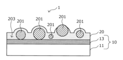
- FIG. 2 is a schematic diagram for explaining an example of a structure of a precoated steel sheet according to an embodiment of the present invention.
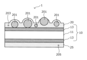
- FIG. 2 is a schematic diagram for explaining an example of a structure of a precoated steel sheet according to the embodiment.
- FIG. 2 is a schematic diagram for explaining an example of a structure of a precoated steel sheet according to the embodiment.
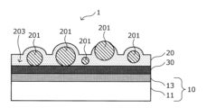
- FIG. 2 is a schematic diagram for explaining an example of a structure of a precoated steel sheet according to the embodiment.
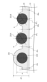
- FIG. 2 is a schematic diagram for explaining a coating layer in the precoated steel sheet according to the embodiment.
- FIGS 1A to 1D are schematic diagrams for explaining an example of the structure of a pre-coated steel sheet according to this embodiment.
- the pre-coated steel sheet means a plated steel sheet having a coating layer on its surface.
- the precoated steel sheet 1 has a zinc-based plated steel sheet 10 and a coating layer 20 located on one surface of the zinc-based plated steel sheet 10.
- the zinc-based plated steel sheet 10 has a base steel sheet 11 that serves as a substrate, and a zinc-based plating layer 13 located on the surface of the base steel sheet 11.
- the coating layer 20 according to this embodiment contains resin particles 201 in a dispersed state.
- a coating layer 20 containing resin particles 201 is provided on one surface of the zinc-based plated steel sheet 10, which is the base material, and a coating layer 25 not containing resin particles 201 may be provided on the other surface of the zinc-based plated steel sheet 10.
- a coating layer 20 containing resin particles 201 may be provided on both surfaces of the zinc-based plated steel sheet 10, which is the base material.
- the precoated steel sheet 1 may further include an anti-rust coating layer 30 between the zinc-based plated steel sheet 10 and the coating layer 20, as an example of a coating layer containing an anti-rust pigment and a resin, if necessary.
- Fig. 1D illustrates a case where an anti-rust coating layer 30 is provided on a pre-coated steel sheet 1 having the structure shown in Fig. 1A, but in a pre-coated steel sheet 1 having a structure such as that shown in Fig. 1B or 1C, an anti-rust coating layer 30 may be further provided at least between the zinc-based plated steel sheet 10 and the coating layer 20 or between the zinc-based plated steel sheet 10 and the coating layer 25.
- the zinc-based plated steel sheet 10 used as the substrate of the pre-coated steel sheet 1 in this embodiment has a base steel sheet 11 and a zinc-based plating layer 13 located on the surface of the base steel sheet 11.
- the base steel plate 11 Various types of steel plate can be used as the base steel plate 11, such as Al-killed steel, ultra-low carbon steel containing Ti, Nb, etc., and high-strength steel in which ultra-low carbon steel further contains strengthening elements such as P, Si, Mn, etc.
- the zinc-based plating layer 13 may be, for example, zinc-based plating such as zinc plating, zinc-nickel plating, zinc-iron plating, zinc-chrome plating, zinc-aluminum plating, zinc-titanium plating, zinc-magnesium plating, zinc-manganese plating, zinc-aluminum-magnesium plating, and zinc-aluminum-magnesium-silicon plating.
- zinc-based plating such as zinc plating, zinc-nickel plating, zinc-iron plating, zinc-chrome plating, zinc-aluminum plating, zinc-titanium plating, zinc-magnesium plating, zinc-manganese plating, zinc-aluminum-magnesium plating, and zinc-aluminum-magnesium-silicon plating.
- the zinc-based plating may contain small amounts of different metal elements or impurities such as cobalt, molybdenum, tungsten, nickel, titanium, chromium, aluminum, manganese, iron, magnesium, lead, bismuth, antimony, tin, copper, cadmium, and arsenic, or may have inorganic substances such as silica, alumina, and titania dispersed therein.
- the zinc-based plating may be a multi-layer plating that combines the above plating with other types of plating (for example, iron plating, iron-phosphorus plating, nickel plating, and cobalt plating).
- the plating method is not particularly limited, and any of the various known plating methods may be used, such as electroplating, hot-dip plating, vapor deposition plating, dispersion plating, vacuum plating, etc.
- zinc-based platings it is particularly preferable to use zinc-aluminum-magnesium alloy plating as the zinc-based plating layer 13, and it is even more preferable to use a zinc-aluminum-magnesium-silicon alloy plating layer containing 4-22 mass% Al, 1-10 mass% Mg, 0.0001-2.0000 mass% Si, with the remainder being Zn and impurities.
- Al 4-22% by mass
- the Al content is more preferably 5 mass% or more.
- the Al content is more preferably 16 mass % or less. be.
- Mg 1 to 10% by mass
- the Mg content is more preferably 2 mass% or more.
- the Mg concentration is adjusted so that the Mg content in the zinc-based plating layer 13 after production is 10 mass % or less, thereby stabilizing the generation of dross in the plating bath and preventing the formation of a zinc-based plating layer 13 in the zinc-based plating layer 13 after production.
- the Mg concentration is adjusted so that the Mg content in the zinc-based plating layer 13 after production is 5 mass % or less. It is more preferable to make an adjustment.
- Si 0.0001 to 2.0000% by mass
- Si content By setting the Si content to 0.0001 mass % or more, the adhesion of the zinc-based plating layer 13 (more specifically, the adhesion between the base steel sheet 11 and the zinc-based plating layer 13) can be further improved.
- Si content By setting the Si content to 2.0000 mass % or less, it is possible to suppress saturation of the adhesion improving effect of the zinc-based plating layer 13 and to further improve the adhesion of the zinc-based plating layer 13. It is possible to improve the Si content.
- the Si content is more preferably 1.6000 mass % or less.
- the zinc-based plating layer 13 may contain elements such as Fe, Sb, and Pb, either alone or in combination, in an amount of 1 mass% or less, in place of a portion of the remaining Zn.
- Examples of zinc-based plated steel sheets 10 provided with a zinc-based plating layer 13 having the above-mentioned chemical composition include hot-dip zinc-aluminum-magnesium alloy plated steel sheets having a Zn-6%Al-3%Mg alloy plating layer, and hot-dip zinc-aluminum-magnesium-silicon alloy plated steel sheets (for example, "Super Dima (registered trademark)" manufactured by Nippon Steel Corporation), such as plated steel sheets having a Zn-11%Al-3%Mg-0.2%Si alloy plating layer.
- the coating weight of the zinc-based plating layer 13 as described above is preferably 30 g/m 2 or more in total on both sides of the steel sheet (i.e., 15 g/m 2 or more per side). By setting the coating weight to 30 g/m 2 or more, it is possible to reliably ensure the corrosion resistance of the zinc-based plated steel sheet 10.
- the coating weight is more preferably 40 g/m 2 or more in total on both sides of the steel sheet.
- the coating weight is preferably 600 g/m 2 or less in total on both sides of the steel sheet (i.e., 300 g/m 2 or less per side).
- the coating weight is more preferably 550 g/m 2 or less in total on both sides of the steel sheet.
- the thickness of the zinc-based plated steel sheet 10 as described above is not particularly limited, and may be set appropriately depending on the mechanical strength (e.g., tensile strength, etc.) and workability required for the precoated steel sheet 1 according to this embodiment.
- the coating layer 20 of the precoated steel sheet 1 according to this embodiment is provided on at least one surface of the zinc-based plated steel sheet 10.
- the coating layer 20 according to this embodiment is a coating layer in which resin particles 201 are present in a dispersed state in a binder resin and a color pigment as film-forming components 203.
- the coating layer 20 according to this embodiment may further contain various additives such as a crosslinking agent in addition to the above-mentioned resin particles 201 and film-forming components 203.
- resin particles 201 are dispersed in the film-forming component 203 in the coating layer 20, and in addition, the resin particles 201 satisfy the conditions described in detail below.
- the binder resin as the film-forming component 203 realizes a predetermined corrosion resistance and scratch resistance.
- the resin particles 201 have a predetermined toughness and ductility.
- the resin particles 201 have a predetermined toughness and ductility, and thus it is possible to mitigate the impact applied to the coating layer 20.
- the scratch resistance of the coating layer 20 can be further improved.
- the resin particles 201 have a predetermined toughness and ductility, and thus it is possible to more effectively prevent the occurrence of pressure marks caused by the binder resin in the deformed portion becoming relatively flat. Furthermore, even if the coating layer 20 is scratched, the scratch can be prevented from reaching the zinc-based plated steel sheet 10, and the corrosion resistance of the precoated steel sheet 1 can be maintained.
- the resin particles 201 can be particles made of various materials as long as they have a predetermined toughness and ductility. However, from the viewpoint of having better toughness and ductility, it is more preferable to use organic resin particles made of organic resin.
- organic resin particles used as particles 201 include resin particles made of acrylic resin, resin particles made of polyester resin, resin particles made of urethane resin, resin particles made of fluorine resin, resin particles made of silicone resin, and resin particles made of polyolefin resin. Among these, it is more preferable to use resin particles made of urethane resin or resin particles made of acrylic resin as resin particles 201, from the viewpoint of more easily achieving the desired toughness and ductility.
- the resin particles 201 when resin particles made of urethane resin or acrylic resin as described above are used as the resin particles 201, it is preferable that the resin constituting these resin particles exhibits a predetermined glass transition temperature Tg.
- the glass transition temperature Tg of the urethane resin is preferably within the range of -40°C to 40°C.
- the glass transition temperature Tg of the acrylic resin is preferably within the range of 40°C to 160°C.
- the resin particles 201 exhibit even more preferable toughness and ductility, and even if an external force is applied to the resin particles 201 and the resin particles 201 are deformed, the resin particles 201 can quickly restore their shape before the impact. This makes it possible to further prevent the occurrence of pressure marks caused by the binder resin in the deformed portion becoming relatively flat.
- the glass transition temperature Tg of the urethane resin is more preferably -10°C or higher. Also, the glass transition temperature Tg of the urethane resin is more preferably 20°C or lower. Also, when resin particles made of an acrylic resin are used as the resin particles 201, the glass transition temperature Tg of the acrylic resin is more preferably 40°C or higher. Also, the glass transition temperature Tg of the acrylic resin is more preferably 120°C or lower.
- the glass transition temperature Tg can be determined, for example, by Thermomechanical Analysis (TMA), in which a needle is inserted into the surface of the particle being measured, a constant temperature change is applied, and the change in thermal expansion of the object being measured is measured.
- TMA Thermomechanical Analysis
- the content of the resin particles 201 in the coating layer 20 is 1.0 to 15.0 mass% per side with respect to the total solid mass of the coating layer 20. If the content of the resin particles 201 in the coating layer 20 is less than 1.0 mass% per side, the content of the resin particles 201 is too low to achieve the desired design of both a textured appearance and a matte appearance. If the content of the resin particles 201 in the coating layer 20 is 1.0 mass% or more per side, the pre-coated steel sheet 1 can achieve the desired design.
- the content of the resin particles 201 in the coating layer 20 per side is preferably 2.0 mass% or more, and more preferably 3.0 mass% or more.
- the content of the resin particles 201 in the coating layer 20 exceeds 15.0% by mass per side, the content of the resin particles 201 becomes too high, and as a result, the scratch resistance required for the coating layer 20 cannot be realized.
- the content of the resin particles 201 in the coating layer 20 per side is preferably 12.0% by mass or less, and more preferably 9.0% by mass or less.
- the coating layer 20 contains a binder resin and a color pigment as film-forming components in addition to the above-mentioned resin particles 201.
- the film-forming components 203 will be described in detail below.
- the binder resin which is one of the film-forming components 203 contained in the coating layer 20 according to this embodiment, can be any material that functions as a binder for the resin particles 201.
- various organic resins include acrylic resins, polyester resins, urethane resins, and fluorine resins.
- the binder resin it is more preferable to select as the binder resin the same type of resin as the resin particles 201 used. This further improves the affinity between the resin particles 201 and the binder resin, making it possible to further improve the adhesion and barrier properties of the coating layer 20.
- the coloring pigment contained in the coating layer 20 according to this embodiment as one type of film-forming component 203 is not particularly limited, and various known coloring agents can be used depending on the color tone required for the coating layer 20.
- coloring agents include aluminum pigments, titanium oxide, zinc oxide, zirconium oxide, calcium carbonate, barium sulfate, kaolin clay, carbon black, iron oxide, Hansa Yellow, pyrazolone orange, phthalocyanine, and azo pigment carbon black.
- the content of the coloring agent may be appropriately set, for example, to about 3 to 60% by mass.
- the coating layer 20 according to this embodiment may contain, in addition to the resin particles 201 as described above and the binder resin and coloring pigment as the film-forming components 203, various additives such as crosslinking agents as necessary.
- the organic resin coating layer 20 according to this embodiment may further contain additives such as anti-rust pigments, extender pigments, surface-modified metal powders or glass powders, dispersants, leveling agents, waxes, aggregates, diluting solvents, etc., as necessary, within the range that does not impair the above-mentioned effects.
- additives such as anti-rust pigments, extender pigments, surface-modified metal powders or glass powders, dispersants, leveling agents, waxes, aggregates, diluting solvents, etc.
- the content is preferably, for example, about 1 to 15 mass %.
- the anti-rust pigment used may be any of various known anti-rust pigments.
- the compressive modulus of the resin particles 201 as described above at 25°C is in the range of 60 to 250 MPa
- the compressive modulus of the binder resin as described above at 25°C is in the range of 60 to 150 MPa
- the compressive modulus of the binder resin at 25°C is equal to or less than the compressive modulus of the resin particles 201 at 25°C.
- the binder resin can more easily follow the deformation of the resin particles 201 (in other words, the binder resin can more easily deform in accordance with the deformation of the resin particles 201). As a result, the occurrence of excess voids between the resin particles 201 and the binder resin is prevented, and the adhesion and barrier properties of the coating layer 20 are further improved.
- the compressive modulus of the resin particles 201 at 25°C is more preferably 90 MPa or more.
- the compressive modulus of the resin particles 201 at 25°C is more preferably 210 MPa or less.
- the compressive modulus of the binder resin at 25°C is more preferably 80 MPa or more.
- the compressive modulus of the binder resin at 25°C is more preferably 130 MPa or less.
- the compressive modulus of the resin particles 201 and the binder resin at 25°C can be determined by focusing on a cross section obtained by cutting the coating layer 20 according to this embodiment in the thickness direction and measuring the compressive stress-strain curve for each of the resin particles 201 and the binder resin. More specifically, in accordance with JIS K 7181:2011, a nanoindenter is pressed into the area corresponding to the resin particles 201 and the area corresponding to the binder resin in the cross section of interest, and the load and displacement are measured. At this time, the measurement temperature is 25°C. From this measurement, a compressive stress-strain curve can be obtained for each of the resin particles 201 and the binder resin. From the obtained compressive stress-strain curve, the compressive modulus of the resin particles 201 and the binder resin can be calculated in accordance with JIS K 7181:2011.
- the above-mentioned measurements are carried out at least 10 locations for each of the resin particles 201 and the binder resin, and the average value of the multiple compressive elastic moduli obtained is taken as the compressive elastic modulus of the resin particles 201 and the binder resin of interest.
- Fig. 2 is an explanatory diagram for explaining the coating layer in the pre-coated steel sheet according to this embodiment.
- the resin particles 201 are present in a dispersed state in the film-forming components 203, such as the binder resin and color pigment, that constitute the coating layer 20.
- the film-forming components 203 such as the binder resin and color pigment, that constitute the coating layer 20.
- FE-SEM field emission scanning electron microscope
- a region having a length of 400 ⁇ m in a direction perpendicular to the thickness direction (hereinafter also referred to as the width direction) is defined as the observation field area for one microscope observation, and 10 such observation field areas are arbitrarily set in the cross section of interest. Then, based on the measurement results obtained at the 10 locations, a characteristic quantity that represents the state of existence of the resin particles 201 is calculated, as described below.
- the average value of the area ratio (i.e., the average area ratio), which is the area ratio occupied by the resin particles 201, is within the range of 5 to 40%.
- the average area ratio is calculated as follows. That is, in the cross section of interest, a certain observation field area (length in the width direction: 400 ⁇ m) is focused on.
- the magnification of the FE-SEM may be an appropriate magnification (for example, about 300 times) such that a coating layer having a length of 400 ⁇ m in the width direction fits in one field of view.
- the area ratio of the resin particles 201 to the total area of the coating layer in the observation field area of this size i.e., the area ratio
- the area ratio is calculated by various functions implemented in the electron microscope, image processing, etc.
- the area ratio of the part of the particle present in the field of view is calculated.
- 10 measured values of the area ratio of the resin particles 201 can be obtained.
- the average value of the 10 measured values obtained in this way is calculated to be the average area ratio of the resin particles 201 in the cross section.
- this average area ratio is the average value of the area ratio of the resin particles to the total area of the coating layer in the 10 observational fields.
- the average area ratio of the resin particles 201 in the cross section is less than 5%, the presence ratio of the resin particles 201 is too small and the desired design cannot be achieved. If the average area ratio of the resin particles 201 is 5% or more, it is possible to achieve an excellent design that combines a grained appearance and a matte appearance.
- the average area ratio of the resin particles 201 in the cross section is preferably 8% or more, and more preferably 10% or more.
- the average area ratio of the resin particles 201 in the cross section exceeds 40%, the proportion of the resin particles 201 is too high, and as a result, not only is it impossible to achieve the scratch resistance required of the coating layer 20, but the desired design (particularly, a matte appearance) cannot be achieved.
- the average area ratio of the resin particles 201 in the cross section is preferably 38% or less, and more preferably 35% or less.
- the average film thickness dA of the coating layer 20 in the portion not containing the resin particles 201 is within the range of 10 to 40 ⁇ m. If the average film thickness dA of the coating layer 20 in the cross section not containing the resin particles 201 is less than 10 ⁇ m, the thickness of the coating layer 20 is too thin and the desired corrosion resistance cannot be achieved. When the average film thickness dA is 10 ⁇ m or more, the corrosion resistance required for the precoated steel sheet 1 according to this embodiment can be achieved.
- the average film thickness dA is preferably 13 ⁇ m or more, more preferably 15 ⁇ m or more.
- the coating layer 20 in the cross-section that does not contain resin particles 201 exceeds 40 ⁇ m, the coating layer 20 becomes too thick, which is undesirable as it reduces the adhesion of the coating layer 20.
- the average film thickness dA is preferably 30 ⁇ m or less, and more preferably 25 ⁇ m or less.
- the average thickness dA of the coating layer 20 in the cross section not containing the resin particles 201 is determined by the following procedure. First, in one observation field of view of interest, the thickness of the coating layer 20 in the portion not containing the resin particles 201 is measured at 10 points. At this time, the thickness of the coating layer 20 in the portion not containing the resin particles 201 may be measured using a length measuring function or the like implemented in the FE-SEM. The average value of the 10 measured values is then calculated and used as the average value of the thickness of the coating layer 20 in the observation field of view of interest. The above operation is performed for any 10 observation fields of view, and the average values obtained from each observation field of view are further averaged by the number of fields of view. The value obtained in this manner is used as the average thickness dA of the coating layer 20 in the portion not containing the resin particles 201.
- the average value of the thickness of the coating layer 20 in one observation field of view of interest is (1/4) x ( dA1 + dA2 + dA3 + dA4 ).
- the average particle diameter ⁇ of the resin particles 201 is 4.0 times or less the average film thickness dA determined as described above. That is, in the coating layer 20 according to this embodiment, the relationship ⁇ 4.0 ⁇ dA is established.
- the average particle diameter ⁇ of the resin particles 201 is more than 4.0 times the average film thickness dA of the coating layer 20, the average particle diameter ⁇ of the resin particles 201 is too large relative to the average film thickness dA, making it difficult for the resin particles 201 to be stably held by the coating layer 20, and as a result, the resin particles 201 tend to fall off, making it impossible to achieve the desired design.
- the ratio ( ⁇ /dA) of the average particle diameter ⁇ to the average film thickness dA is preferably 3.8 or less, and more preferably 3.5 or less.
- the average particle size ⁇ of the resin particles 201 is preferably within the range of 9 to 70 ⁇ m.
- the average particle size ⁇ of the resin particles 201 is preferably within the range of 9 to 70 ⁇ m.
- the average particle diameter ⁇ of the resin particles 201 is more preferably 13 ⁇ m or more, and even more preferably 17 ⁇ m or more.
- the average particle diameter ⁇ of the resin particles 201 is more preferably 60 ⁇ m or less, and even more preferably 55 ⁇ m or less.
- the average particle size ⁇ of the resin particles 201 in the cross section as described above is determined by the following procedure. First, in a cross section obtained by cutting the coating layer 20 at an arbitrary position, focus is placed on one arbitrary observation region as described above. In the observation region, the circle equivalent diameters of the resin particles 201 present in the region are measured. Then, the average value of the measured circle equivalent diameters in the observation region of interest is calculated. This measurement is performed on 10 arbitrary observation field regions, and the average values obtained from each observation field region are further averaged by the number of fields. The value obtained in this manner is the average particle size ⁇ of the resin particles 201.
- the average value of the circle-equivalent diameters of the resin particles 201 in the observation field of view is calculated as (1/3) x ( ⁇ 1 + ⁇ 2 + ⁇ 3 ).
- Such measurements are performed for 10 arbitrary observation field of views in the specified cross section, and the obtained average values are further averaged by the number of views to obtain the average particle diameter ⁇ of the resin particles 201.
- the value of the ratio ( ⁇ /dA) of the average particle diameter ⁇ to the average film thickness dA is preferably 0.2 or more, more preferably 0.3 or more, even more preferably 1.0 or more, and even more preferably more than 1.0. This is because when the average particle diameter ⁇ is less than 0.2 of the average film thickness dA of the coating layer 20, the average particle diameter ⁇ of the resin particles 201 is too small compared to the average film thickness dA, so that the resin particles 201 are completely buried in the coating layer 20, making it difficult for the resin particles 201 to contribute to the unevenness of the surface, and as a result, the desired design cannot be achieved.
- ⁇ Average actual thickness of coating layer 20 dB In the above-described cross section of the coating layer 20 according to the present embodiment, attention will be focused on a portion containing the resin particles 201. In such a portion of the coating layer 20 containing the resin particles 201, the thickness obtained by subtracting the thickness of the portion corresponding to the resin particles 201 from the total thickness of the coating layer 20 including the resin particles 201 will be referred to as the substantial film thickness of the coating layer 20 in the portion containing the resin particles 201.
- the total thickness of the coating layer 20 containing the resin particles 201 is defined as the length from the interface position of the coating layer 20 on the zinc-based plated steel sheet 10 side to the surface of the coating layer 20 at the position of the part containing the resin particles 201 in the cross section (the length to the surface of the coating layer 20 in a direction parallel to the surface normal direction of the zinc-based plated steel sheet 10).
- the thickness of the part corresponding to the resin particles 201 is defined as the sum of the lengths of the parts corresponding to the resin particles 201 in the direction parallel to the surface normal direction of the zinc-based plated steel sheet 10 at the part of interest in the total thickness as described above.
- this average actual film thickness dB is within the range of 4 to 30 ⁇ m.
- the average real thickness dB of the coating layer 20 is less than 4 ⁇ m, the amount of film-forming component 203 present in the portion where the resin particles 201 are present is too small, and as a result, the resin particles 201 are likely to fall off, and the desired design cannot be achieved. Also, as a result of the amount of film-forming component 203 being too small, the corrosion resistance and scratch resistance required of the coating layer 20 cannot be achieved.
- the average real thickness dB of the coating layer 20 is preferably 5 ⁇ m or more, and more preferably 7 ⁇ m or more.
- the average real film thickness dB of the coating layer 20 exceeds 30 ⁇ m as described above, the amount of film-forming component 203 present in the portion where the resin particles 201 are present will be too large, and the desired design (particularly, a matte appearance) will not be achieved.
- the average real film thickness dB of the coating layer 20 is preferably 28 ⁇ m or less, and more preferably 25 ⁇ m or less.
- the average real film thickness dB in the cross section as described above is determined by the following procedure. First, in a cross section obtained by cutting the coating layer 20 at an arbitrary position, focus on one arbitrary observation area as described above. In the observation area, focus on an arbitrary position where the resin particle 201 is present, and measure the total thickness of the coating layer 20 and the thickness of the part corresponding to the resin particle 201. By using the two obtained measured values and subtracting (total thickness of the coating layer 20 - thickness of the part corresponding to the resin particle 201), the real film thickness of the coating layer 20 at the position of interest can be obtained. Such measurements and calculations are performed at any 10 points in the observation area of interest.
- the obtained multiple real film thickness measurements are averaged by the number of observation points to obtain the average real film thickness in the observation area of interest. Such measurements are performed for any 10 observation field areas, and the average values obtained from each observation field area are further averaged by the number of fields. The value obtained in this way is the average actual thickness dB of the coating layer 20.
- three resin particles 201 are present in the field of view.
- the thickness corresponding to the resin particle 201 is ⁇ 1 , which is the particle diameter of the resin particle 201. If the total thickness of the coating layer 20 is dT 1 , the real film thickness dB 1 at that portion is dT 1 - ⁇ 1.
- the thickness corresponding to the resin particle 201A is ⁇ 2 , which is the particle diameter of the resin particle 201A.
- the real film thickness dB 2 at that portion is dT 2 - ⁇ 2.
- the thickness corresponding to the resin particle 201B is ⁇ 3 , which is the particle diameter of the resin particle 201B.
- the actual film thickness dB 3 at that portion is dT 3 - ⁇ 3.
- exposed resin particles those having a portion at the outer periphery that is not covered with the film-forming component 203 having a thickness of 1 ⁇ m or more are referred to as exposed resin particles.
- Such exposed resin particles include not only resin particles in which a portion is exposed and not covered with the film-forming component 203, such as resin particle 201B shown at the far right of Figure 2, but also resin particles in which the outer periphery is covered with the film-forming component 203, but the thickness of the film-forming component 203 covering the outer periphery is less than 1 ⁇ m, such as resin particle 201A shown in the center of Figure 2.
- the average number ratio of exposed resin particles (hereinafter referred to as the average number ratio) is 5 to 50%. If the average number ratio of exposed resin particles is less than 5%, the surface appearance will lack a grained texture, which is not preferred as the desired design cannot be achieved. If the average number ratio of exposed resin particles is 5% or more, it is possible to impart a grained texture, which is preferred as the desired design can be achieved.
- the average number ratio of exposed resin particles is preferably 8% or more, and more preferably 10% or more.
- the average percentage of exposed resin particles is more than 50%, the proportion of resin particles 201 exposed on the surface of the coating layer 20 becomes too high, and as a result, the resin particles 201 are easily shed, and the desired scratch resistance cannot be achieved. Also, if the average percentage of exposed resin particles is more than 50%, the proportion of resin particles 201 exposed on the surface of the coating layer 20 becomes too high, and as a result, the desired design (particularly, a matte appearance) cannot be achieved. By keeping the average percentage of exposed resin particles at 50% or less, the desired design can be achieved while ensuring the scratch resistance required of the coating layer 20.
- the average percentage of exposed resin particles is preferably 47% or less, and more preferably 45% or less.
- the film-forming component 203 it is preferable that 80% or more of the exposed resin particles along the outer periphery are covered with the film-forming component 203.
- the film-forming component 203 By covering 80% or more of the exposed resin particles along the outer periphery with the film-forming component 203, even the exposed resin particles are less likely to fall off the coating layer 20, making it possible to further prevent deterioration of scratch resistance and design. It is more preferable that 85% or more of the exposed resin particles along the outer periphery are covered with the film-forming component 203.
- the average number ratio of exposed resin particles in a cross section as described above is determined by the following procedure. First, in a cross section obtained by cutting the coating layer 20 at an arbitrary position, focus on one arbitrary observation target area as described above. In the observation target area, the number of all resin particles 201 present in the area is counted, and exposed resin particles are identified and counted to determine their number ratio. In this case, if only a part of a particle is present in the field of view, rather than the entire particle, the number is counted to one decimal place, for example, 0.1 to 0.9, depending on the area ratio of the particle present in the field of view.
- Such measurements are performed for 10 arbitrary observation field areas, and the measurement results of the number ratio obtained from each observation field of view are further averaged by the number of fields of view.
- the value obtained in this manner is the average number ratio of exposed resin particles.
- the decimal point is rounded down.
- magnification of the FE-SEM should be set to an appropriate magnification (e.g., about 300x) so that a coating layer 400 ⁇ m long in the width direction fits into one field of view.
- the extent to which the film-forming component 203 covers the length along the periphery of the resin particle 201 can be calculated by measuring the length of the periphery of each exposed resin particle and the length of the portion exposed from the coating layer 20 using a length measuring function implemented in the FE-SEM. Such measurements are performed for all exposed resin particles present in the observation area of interest, and the average of the obtained proportions is calculated. This operation is performed for any 10 observation field areas, and the average of the proportions obtained from each observation field area is further averaged by the number of fields. The value obtained in this way can be used as the proportion of the periphery of the exposed resin particle.
- ⁇ Use of Two Types of Resin Particles 201> In the coating layer 20 according to this embodiment, it is preferable to use two types of resin particles having different average particle sizes as the previously described resin particles 201.
- the resin particles having a relatively large average particle size will be referred to as large-particle-size resin particles
- the resin particles having a relatively small average particle size will be referred to as small-particle-size resin particles.
- the above-mentioned large-diameter resin particles as the resin particles 201 in the coating layer 20 according to this embodiment it is possible to realize significant unevenness on the surface of the coating layer 20, and it is possible to realize high designability (embossed appearance and matte appearance) as explained above.
- the above-mentioned small-diameter resin particles as the resin particles 201 it is possible to realize unevenness that protrudes more gently than the unevenness formed by the large-diameter resin particles, and it is also possible to form surface undulations that gently connect the unevenness formed by the large-diameter resin particles. As a result, it is possible to further improve the designability of the precoated steel sheet 1 according to this embodiment.
- the coating layer 20 was referred to as "a portion containing resin particles 201" and "a portion not containing resin particles 201.”
- the "portion not containing resin particles 201" refers to a portion that does not contain either large-diameter resin particles or small-diameter resin particles.
- the coating layer 20 it is preferable to use large-sized resin particles having an average particle size in the range of 40 to 70 ⁇ m that give a peak in the particle size range of 55 ⁇ 10 ⁇ m when the particle size distribution is measured, as the large-sized resin particles, and it is preferable to use small-sized resin particles having an average particle size in the range of 9 to 26 ⁇ m that give a peak in the particle size range of 17 ⁇ 8 ⁇ m when the particle size distribution is measured, as the small-sized resin particles.
- large-sized resin particles and small-sized resin particles it is possible to further improve the design of the precoated steel sheet 1.
- the large-diameter resin particles have a peak particle size within the particle size range of 55 ⁇ 5 ⁇ m and an average particle size within the range of 45 to 65 ⁇ m
- the small-diameter resin particles have a peak particle size within the particle size range of 17 ⁇ 5 ⁇ m and an average particle size within the range of 12 to 22 ⁇ m.
- the ratio ( ⁇ L/ ⁇ H) of the average particle size ⁇ L of the small resin particles to the average particle size ⁇ H of the large resin particles is preferably within the range of 0.14 to 0.58.
- the average particle size ratio ( ⁇ L/ ⁇ H) is more preferably 0.20 or more.
- the average particle size ratio ( ⁇ L/ ⁇ H) is more preferably 0.50 or less.
- the content ratio CL of the small-sized resin particles is preferably within a range of 5 to 30 mass % relative to the total solid mass of the coating layer 20
- the content ratio CH of the large-sized resin particles is preferably within a range of 5 to 30 mass % relative to the total solid mass of the coating layer 20.
- the proportion CL of small-sized resin particles is more preferably 7 mass% or more with respect to the total solid mass of the coating layer 20.
- the proportion CL of small-sized resin particles is more preferably 25 mass% or less with respect to the total solid mass of the coating layer 20.
- the proportion CH of large-sized resin particles is more preferably 7 mass% or more with respect to the total solid mass of the coating layer 20.
- the proportion CH of large-sized resin particles is more preferably 25 mass% or less with respect to the total solid mass of the coating layer 20.
- the ratio (CL/CH) of the content proportion of small resin particles CL to the content proportion of large resin particles CH is preferably within the range of 0.5 to 1.5.
- the content proportion ratio (CL/CH) is more preferably 0.7 or more.
- the content proportion ratio (CL/CH) is more preferably 1.3 or less.
- the compressive modulus of the small resin particles at 25°C is preferably within the range of 60 to 250 MPa, and the compressive modulus of the large resin particles at 25°C is preferably within the range of 60 to 250 MPa.
- the compressive modulus of the small resin particles at 25°C is more preferably 90 MPa or more.
- the compressive modulus of the small resin particles at 25°C is more preferably 210 MPa or less.
- the compressive modulus of the large resin particles at 25°C is more preferably 90 MPa or more.
- the compressive modulus of the large resin particles at 25°C is more preferably 210 MPa or less.
- the method when determining the average particle size and content of the large-diameter resin particles and the small-diameter resin particles by cross-sectional observation, the method is not particularly limited, but may be, for example, as follows. That is, first, in a cross-section obtained by cutting the coating layer 20 at an arbitrary position, focus on one arbitrary observation target area as described above. In the observation target area, the circle equivalent diameters of the resin particles 201 present in the area are measured. Then, the average value of the measured circle equivalent diameters in the observation target area of interest is calculated. Such measurements are performed for 10 arbitrary observation field areas, and a particle size distribution is obtained from each observation field area.
- resin particles having a particle size of 40 ⁇ m or more are regarded as large-diameter resin particles, and their average is regarded as the average particle size of the large-diameter resin particles.
- resin particles having a particle size of 30 ⁇ m or less are regarded as small-diameter resin particles, and their average is regarded as the average particle size of the small-diameter resin particles.
- the percentage of resin particle content can be measured as follows. First, the total mass per unit volume of the coating, including the resin particles, is calculated from the volume of the coating calculated from the average film thickness dA of the coating determined by cross-sectional observation, and the mass difference when the coating is removed from the steel sheet using an organic solvent or remover. Similarly, the average particle diameter of the resin particles determined by cross-sectional observation is converted into the volume of the resin particles, and the total mass of the resin particles contained in the coating layer per unit volume is calculated when the specific gravity of the resin particles is 1.2. The percentage of resin particle content can be calculated from the total mass per unit volume of the coating and the total mass of the resin particles per unit volume.
- the compressive modulus of the large and small resin particles at 25°C can be measured in accordance with the method for measuring the compressive modulus of the resin particles and binder resin described above.
- the coating layer 20 according to this embodiment has been described in detail above with reference to FIG. 2.
- the coating layer 25 that the precoated steel sheet 1 according to this embodiment may have may have the same configuration as the coating layer 20, except that it does not have the resin particles 201 as described above. That is, the coating layer 25 has at least a binder resin as the film-forming component 205, and may further have various color pigments and additives that the coating layer 20 may contain as described above. Therefore, detailed description of the coating layer 25 according to this embodiment will be omitted below.
- the rust-preventive coating layer 30 is a coating layer that contains an anti-rust pigment and a resin.
- the resin contained in the rust-preventive coating layer 30 functions as a film-forming component, and any material can be used. However, from the standpoint of ease and cost of production, as well as corrosion resistance and scratch resistance, it is preferable to use various organic resins as the resin. Examples of such resins include acrylic resins, polyester resins, urethane resins, and fluorine resins.
- the anti-rust coating layer 30 according to this embodiment can contain various known anti-rust pigments as the anti-rust pigment. However, it is preferable that the anti-rust coating layer 30 according to this embodiment contains a pigment containing at least one of the elements P, V, Si, and Mg as the anti-rust pigment.
- pigments containing at least one of the above elements P, V, Si, and Mg include zinc phosphate, zinc phosphite, zinc magnesium phosphate, magnesium phosphate, magnesium phosphite, silica, calcium ion-exchanged silica, zirconium phosphate, aluminum dihydrogen tripolyphosphate, zinc oxide, zinc phosphomolybdate, barium metaborate, and strontium chromate.
- the average thickness of the anti-rust coating layer 30 is not particularly limited, but may be, for example, about 3.0 to 12.0 ⁇ m.
- the average thickness dA in the portion of the coating layer 20 that does not contain resin particles and the average actual thickness dB, which is the average value of the actual thickness in the portion that contains resin particles also include the thickness of the coating layer between the zinc-based plated steel sheet 10 such as the rust-preventive coating layer 30 and the coating layer 20.
- the value of the 60-degree specular gloss G S (60°) is preferably within the range of 3 or more and 30 or less.
- the surface of the coating layer 20 exhibits a gloss within the above range, so that the precoated steel sheet 1 according to the present embodiment exhibits a more excellent matte appearance (and thus a more excellent design).
- the value of the 60-degree specular gloss G S (60°) is more preferably 3 or more.
- the value of the 60-degree specular gloss G S (60°) is more preferably 25 or less.
- the rate of change in the 60 degree specular gloss Gs (60°) before and after imparting the tensile elongation is 60% or less.
- the imparting of tensile elongation to the precoated steel sheet 1 may be carried out by taking a No. 5 test piece from the precoated steel sheet 1 in accordance with JIS Z2241:2011 and using a tensile tester.
- the rate of change in 60 degree specular gloss Gs (60°) before and after imparting a 30% tensile elongation is 60% or less, even if various processes are applied to the pre-coated steel sheet 1 according to this embodiment, the change in gloss before and after the processing is suppressed. As a result, it becomes possible to maintain the design properties of the pre-coated steel sheet 1 even after various processes are applied.
- the rate of change in 60 degree specular gloss G S (60°) before and after the application of a tensile elongation of 30% is more preferably 50% or less.
- the 60-degree specular gloss G S (60°) can be measured using various gloss meters conforming to JIS Z 8741:1997.
- the precoated steel sheet 1 according to this embodiment has been described in detail above with reference to Figures 1A to 2.
- anti-rust paints for forming an anti-rust coating layer 30 are applied to the zinc-based plated steel sheet and dried.
- the application of the above-mentioned anti-rust paint can be carried out by a generally known application method, such as roll coating, curtain flow coating, air spray, airless spray, immersion, bar coating, brush coating, etc.
- a generally known application method such as roll coating, curtain flow coating, air spray, airless spray, immersion, bar coating, brush coating, etc.
- any method may be used, such as hot air, near infrared rays, far infrared rays, induction heating, or a combination of these.
- a coating liquid for forming the coating layer 20 is applied to the surface of the zinc-based plated steel sheet 10 on which the rust-proofing coating layer has been formed as necessary, and the coating layer is formed by heating and drying.
- the coating liquid is prepared by adding the above-mentioned resin particles, film-forming components including a binder resin and a coloring pigment, and various additives as necessary, to a solvent.
- curtain flow coater it is also important to use a curtain flow coater to apply the prepared coating solution.
- a curtain flow coater By using a curtain flow coater to apply a coating solution containing particles, it is possible to apply the coating solution without causing the particles to settle or causing coating defects (roping).
- the coating liquid is heated and cured.
- the heating temperature may be set according to the solvent used, but is preferably within the range of 180 to 250°C.
- the rate of temperature rise More specifically, it is important to set the rate of temperature rise within the range of 5 to 50°C/sec.
- the method for heating the coating liquid is not particularly limited, and any method may be used, such as hot air, near infrared rays, far infrared rays, induction heating, or a combination of these.
- pre-coated steel sheet according to this embodiment will be specifically described with reference to examples and comparative examples. Note that the examples shown below are merely examples of the pre-coated steel sheet according to this embodiment, and the pre-coated steel sheet according to this embodiment is not limited to the examples below.
- top coating material Preparation of top coating material> Amorphous polyester resins manufactured by Toyobo Co., Ltd., "Vylon (registered trademark) 500 (Tg 4°C)", “Vylon (registered trademark) 270 (Tg 50°C)” and “Vylon (registered trademark) UR-6100 (Tg -30°C)” were dissolved in an organic solvent (a mixture of cyclohexanone and Solvesso 150 (trade name) at a mass ratio of 1:1 was used). Here, the mixing ratio of these polyester resins was adjusted.
- melamine resin "Cymel (registered trademark) 303" manufactured by Allnex Japan Co., Ltd. and melamine resin "Super Beckamine (registered trademark)” manufactured by DIC Corporation were added to the above solution as a hardener.
- the amount of melamine resin added was such that the polyester resin solids:melamine resin solids mass ratio of the resin solids was 70:30.
- 0.5 mass% of acid catalyst "Catalyst 600" manufactured by Allnex Japan Co., Ltd. was further added to this mixed solution of polyester resin and melamine resin.
- the mixed solution was stirred to obtain a varnish paint.
- the polyester resin and melamine resin contained in this varnish paint mainly function as binder resins.
- the compressive modulus of the binder resin was adjusted by adjusting the ratio of the polyester resin and the ratio of the melamine resin.
- the coloring pigments were used such that the mass ratio (carbon black:titanium oxide) of the carbon black and titanium oxide was 20:80.
- the amount of the coloring pigment added was such that the mass ratio (varnish solids:colorant) of the solid content of the varnish and the colorant was 92:8.
- the mixed liquid was stirred to prepare a resin particle-containing paint.
- examples in which the particle size distribution of resin particles has two peaks correspond to resin particle-containing paints prepared using a combination of two types of resin particles in which one peak is observed in the particle size distribution.
- the backside paint used was "Flexcoat 100", a polyester/melamine paint manufactured by Nippon Paint Industrial Coatings Co., Ltd. In this case, a paint colored beige using white pigment, yellow pigment, etc. was used. The gloss level was adjusted by adding silica fine particles as a gloss regulator to the paint. The dry film thickness was set to 5 ⁇ m.
- anti-rust pigments condensed aluminum "K-WHITE #450H” manufactured by Teika Corporation, calcium-modified silica "SHIELDEX C303” manufactured by Grace Corporation, calcium vanadate apatite (reagent manufactured by Fujifilm Wako Pure Chemical Industries, Ltd.), and magnesium hydroxide (reagent manufactured by Kanto Chemical Co., Ltd.) were used. Each was added so that the concentration in the dried film was 50 mass %, and the mixture was stirred to prepare an anti-rust paint.
- test materials a Zn-0.2 mass% Al plated steel sheet (GI), a Zn-11 mass% Al-3 mass% Mg-0.2 mass% Si plated steel sheet (SD), and a Zn-6 mass% Al-3 mass% Mg plated steel sheet (ZAM) (all manufactured by Nippon Steel Corporation) were used.
- the thickness of each zinc-based plated steel sheet was 0.6 mm.
- a chemical conversion coating was formed on the surface of the zinc-based plated steel sheet prior to the application of the paint.
- the chemical conversion coating was formed by applying a chromate-free chemical conversion coating solution "CT-E300N” manufactured by Nihon Parkerizing Co., Ltd. under conditions such that the amount of adhesion after drying would be 100 mg/ m2 , and drying the steel sheet at a temperature of 60°C.
- Two layers of the above-mentioned anti-rust paint and resin particle-containing paint were applied to one side of the above-mentioned zinc-plated steel sheet, and a backside paint was applied to the other side, followed by heating and baking.
- the maximum plate thickness temperature was 210°C for the anti-rust coating layer and 230°C for the coating layer containing resin particles, and the heating rate was 5°C/sec.
- a curtain flow coater was used to apply the above-mentioned paint. In this way, the test specimens were prepared. Here, multiple such test specimens were prepared for each level.
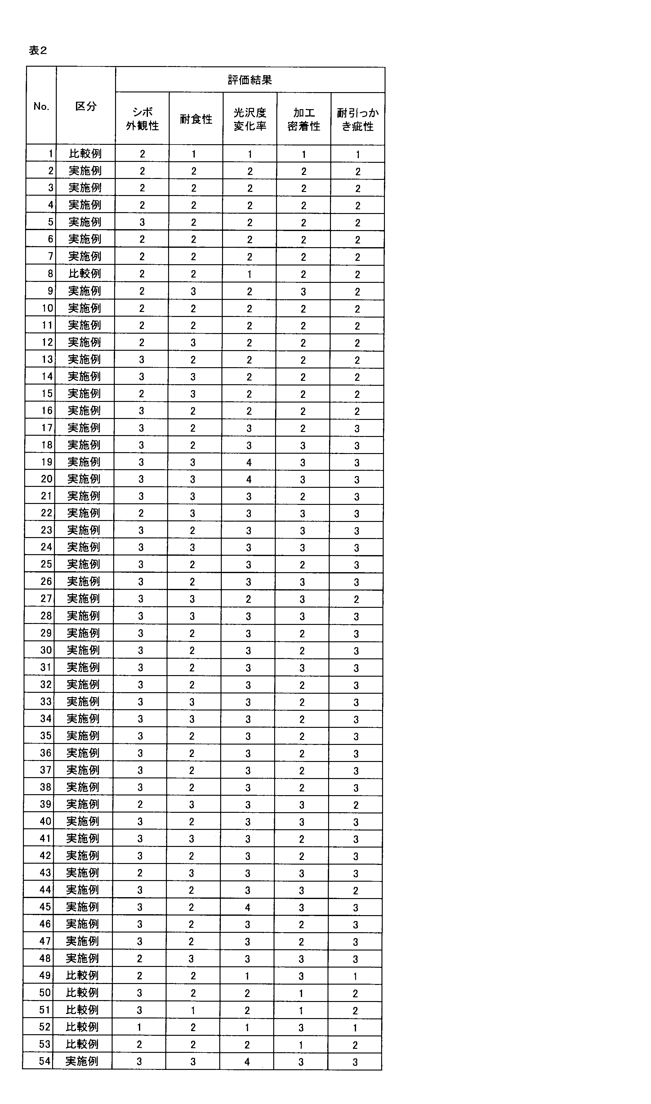
- test material obtained as described above was evaluated from the standpoints of grain appearance, corrosion resistance, gloss change rate before and after tensile elongation, processing adhesion, and scratch resistance.
- the evaluation methods are as follows.
- the evaluation criteria are as follows. The pass level was set to 2 or more. ⁇ Evaluation criteria> Rating 4: The rate of change in gloss is 40% or less. 3: The rate of change in gloss is more than 40% and 50% or less. 2: The rate of change in gloss is more than 50% and not more than 60%. 1: The rate of change in glossiness is more than 60%.
- the surface of the test material was bent at 180 degrees 0T in accordance with JIS K 5600:1999 so that the evaluation surface was on the outside, and the cross section of the coating film in a region of 5 mm from the top of the bent head was observed to measure whether resin particles had fallen off.
- the cross section of the coating film was observed with a scanning electron microscope (JSM-7200F manufactured by JEOL Ltd.).
- the corrosion resistance was evaluated according to the following evaluation criteria. A pass level was 2 or higher. ⁇ Evaluation criteria> Rating 3: No resin particles were observed to fall off from the coating film. 2: Five or fewer resin particles fell off from the coating film. 1: Six or more resin particles were found to have fallen off from the coating film.
- the surface of the test material was scratched 5 mm long with a 5H pencil according to JIS K 5600:1999 to measure whether large-diameter resin particles had fallen off. The scratched surface was observed with an optical microscope.
- the corrosion resistance was evaluated according to the following evaluation criteria. A pass level was 2 or higher. ⁇ Evaluation criteria> Rating 3: No resin particles were observed to fall off from the coating film. 2: Five or fewer resin particles fell off from the coating film. 1: Six or more resin particles were found to have fallen off from the coating film.
- test materials corresponding to the examples of the present invention exhibited excellent grain appearance, corrosion resistance, gloss change rate before and after tensile elongation, processing adhesion, and scratch resistance, while the test materials corresponding to the comparative examples of the present invention failed in at least one of the grain appearance, corrosion resistance, gloss change rate before and after tensile elongation, processing adhesion, and scratch resistance.
- the productivity was compared when the paint was applied using a curtain flow coater and a roll coater commonly used in the manufacture of precoated steel sheets.
- the roll coater used was a two-roll coater consisting of a pickup roll and an applicator roll.
- the substrate speed was changed in 10 mpm increments between 10 mpm and 80 mpm.
- a precoated steel sheet comprising: a zinc-based plated steel sheet having a zinc-based plated layer, which is a plated layer containing at least zinc, located on a surface of a base steel sheet; and a coating layer located on the surface of the zinc-based plated layer, the coating layer contains resin particles, and a binder resin and a color pigment as film-forming components,
- the average area ratio which is the area ratio occupied by the resin particles, is within a range of 5 to 40%
- the average film thickness dA of the coating layer in a portion not containing the resin particles is within a range of 10 to 40 ⁇ m
- the average particle diameter ⁇ of the resin particles is 4.0 times or less the average film thickness dA, In a portion of the coating layer containing the resin particles, when a thickness obtained by subtracting a thickness of a portion corresponding to the resin particles from a
- the precoated steel sheet according to (1) wherein in the cross section, 80% or more of the exposed resin particle's length along the outer periphery is covered with the film-forming component.
- the binder resin has a compressive elastic modulus at 25° C.
- the compressive elastic modulus of the resin particles at 25° C. is within a range of 60 to 250 MPa, and The precoated steel sheet according to any one of (1) to (3), wherein the compressive modulus of the binder resin at 25° C. is equal to or lower than the compressive modulus of the resin particles at 25° C.
- the coating layer contains, as the resin particles, small-diameter resin particles having an average particle size in the range of 9 to 26 ⁇ m, which peaks in a particle size range of 17 ⁇ 8 ⁇ m when the particle size distribution is measured; Large-diameter resin particles having an average particle size in the range of 40 to 70 ⁇ m that peaks in the particle size range of 55 ⁇ 10 ⁇ m;
- the precoated steel sheet according to claim 1 or 2 which contains any one of (1) to (4).
- the content ratio CL of the small-particle resin particles is within a range of 5 to 30 mass % relative to the total solid content mass of the coating layer
- the compressive elastic modulus of the small particle diameter resin particles at 25° C. is within a range of 60 to 250 MPa;
Landscapes
- Chemical & Material Sciences (AREA)
- Engineering & Computer Science (AREA)
- Materials Engineering (AREA)
- Organic Chemistry (AREA)
- Mechanical Engineering (AREA)
- Metallurgy (AREA)
- Chemical Kinetics & Catalysis (AREA)
- Life Sciences & Earth Sciences (AREA)
- Wood Science & Technology (AREA)
- Laminated Bodies (AREA)
- Application Of Or Painting With Fluid Materials (AREA)
Abstract
Description
かかる知見に基づき完成された本発明の要旨は、以下の通りである。
(2)前記断面において、前記露出樹脂粒子は、前記外周部に沿った長さの80%以上が、前記造膜成分で覆われている、(1)に記載のプレコート鋼板。
(3)前記プレコート鋼板に対して30%の引張伸びを付与する前後で、前記塗膜層の表面について、JIS Z 8741:1997で規定される60度鏡面光沢度GS(60°)を測定したときに、前記引張伸びを付与する前後での前記60度鏡面光沢度GS(60°)の変化率は、60%以下である、(1)又は(2)に記載のプレコート鋼板。
(4)前記バインダー樹脂の25℃における圧縮弾性率は、60~150MPaの範囲内であり、前記樹脂粒子の25℃における圧縮弾性率は、60~250MPaの範囲内であり、かつ、前記バインダー樹脂の25℃における圧縮弾性率は、前記樹脂粒子の25℃における圧縮弾性率以下である、(1)又は(2)に記載のプレコート鋼板。
(5)前記塗膜層は、前記樹脂粒子として、粒度分布を測定したときに、粒径17±8μmの範囲内にピークを与える平均粒径が9~26μmの範囲内である小粒径樹脂粒子と、粒径55±10μmの範囲内にピークを与える平均粒径が40~70μmの範囲内である大粒径樹脂粒子と、を含有する、請求項1又は2に記載のプレコート鋼板。
(6)前記小粒径樹脂粒子の含有量の割合CLは、前記塗膜層の全固形分質量に対して、5~30質量%の範囲内であり、前記大粒径樹脂粒子の含有量の割合CHは、前記塗膜層の全固形分質量に対して、5~30質量%の範囲内である、(5)に記載のプレコート鋼板。
(7)前記小粒径樹脂粒子の含有量の割合CLと、前記大粒径樹脂粒子の含有量の割合CHとの比率(CL/CH)は、0.5~1.5の範囲内である、(5)に記載のプレコート鋼板。
(8)前記小粒径樹脂粒子の平均粒径φLと、前記大粒径樹脂粒子の平均粒径φHと、の比率(φL/φH)は、0.14~0.58の範囲内である、(5)に記載のプレコート鋼板。
(9)前記小粒径樹脂粒子の25℃における圧縮弾性率は、60~250MPaの範囲内であり、前記大粒径樹脂粒子の25℃における圧縮弾性率は、60~250MPaの範囲内である、(5)に記載のプレコート鋼板。
<プレコート鋼板の構造>
以下では、まず、図1A~図1Dを参照しながら、本発明の実施形態に係るプレコート鋼板の構造について説明する。図1A~図1Dは、本実施形態に係るプレコート鋼板の構造の一例を説明するための模式図である。ここで、本実施形態において、プレコート鋼板とは、表面に塗膜層を有するめっき鋼板を意味する。
上記のように、本実施形態に係るプレコート鋼板1の基材として用いられる亜鉛系めっき鋼板10は、母材鋼板11と、かかる母材鋼板11の表面上に位置する亜鉛系めっき層13と、を有している。
Alの含有量を4質量%以上とすることで、鋼板の耐食性をより向上させることが可能となる。Alの含有量は、より好ましくは5質量%以上である。一方、Alの含有量を22質量%以下とすることで、上記のような耐食性向上効果の飽和を抑制しながら、鋼板の耐食性をより向上させることが可能となる。Alの含有量は、より好ましくは16質量%以下である。
Mgの含有量を1質量%以上とすることで、鋼板の耐食性をより向上させることが可能となる。Mgの含有量は、より好ましくは2質量%以上である。一方、めっき層の形成に用いるめっき浴において、製造後の亜鉛系めっき層13におけるMgの含有量が10質量%以下となるようなMg濃度に調整を行うことで、めっき浴でのドロス発生を安定化させて、めっき鋼板を安定的に製造することが可能となる。亜鉛系めっき層13の形成に用いるめっき浴において、製造後の亜鉛系めっき層13におけるMgの含有量が5質量%以下となるようなMg濃度に調整を行うことが、より好ましい。
Siの含有量を0.0001質量%以上とすることで、亜鉛系めっき層13の密着性(より詳細には、母材鋼板11と亜鉛系めっき層13との密着性)をより向上させることが可能となる。一方、Siの含有量を2.0000質量%以下とすることで、亜鉛系めっき層13の密着性向上効果の飽和を抑制しつつ、亜鉛系めっき層13の密着性をより向上させることが可能となる。Siの含有量は、より好ましくは1.6000質量%以下である。
続いて、本実施形態に係るプレコート鋼板1が有する塗膜層20について説明する。本実施形態に係る塗膜層20は、亜鉛系めっき鋼板10の少なくとも一方の面上に設けられる。本実施形態に係る塗膜層20は、図1A~図1Dに例示したように、樹脂粒子201が、造膜成分203としてのバインダー樹脂及び着色顔料中に分散した状態で存在している皮膜層である。また、本実施形態に係る塗膜層20は、上記の樹脂粒子201及び造膜成分203に加えて、更に、架橋剤等の各種の添加剤を含有していてもよい。
本実施形態に係る塗膜層20において、樹脂粒子201は、所定の靭性、展延性を有していることがより好ましい。樹脂粒子201が所定の靭性、展延性を有していることで、塗膜層20に加えられた衝撃を緩和することが可能となる。その結果、本実施形態に係るプレコート鋼板1では、塗膜層20の耐疵付き性をより向上させることができる。また、樹脂粒子201が所定の靭性、展延性を有していることで、変形した部分のバインダー樹脂が相対的に平坦となることに起因するプレッシャーマークの発生を、より防止することが可能となる。更に、仮に塗膜層20に疵が付いたとしても、疵が亜鉛系めっき鋼板10に到達することを防止でき、プレコート鋼板1の耐食性を保持することができる。
本実施形態に係る塗膜層20は、上記の樹脂粒子201に加えて、造膜成分としてのバインダー樹脂及び着色顔料を有している。以下では、かかる造膜成分203について、詳細に説明する。
本実施形態に係る塗膜層20が含有する、造膜成分203の一種としてのバインダー樹脂は、樹脂粒子201のバインダーとして機能するものであれば、任意の素材を用いることが可能である。ただし、製造の簡便性及びコスト性の観点、並びに、耐食性及び耐疵付き性の観点から、かかるバインダー樹脂として、各種の有機樹脂を用いることが好ましい。このようなバインダー樹脂として、例えば、アクリル系樹脂、ポリエステル系樹脂、ウレタン系樹脂、フッ素系樹脂等を挙げることができる。
本実施形態に係る塗膜層20が含有する、造膜成分203の一種としての着色顔料については、特に規定されるものではなく、塗膜層20に求められる色調に応じて、公知の各種の着色剤を用いることが可能である。このような着色剤として、例えば、アルミ顔料、酸化チタン、酸化亜鉛、酸化ジルコニウム、炭酸カルシウム、硫酸バリウム、カオリンクレー、カーボンブラック、酸化鉄、ハンザイエロー、ピラゾロンオレンジ、フタロシアニン、アゾ系顔料カーボンブラック等を挙げることができる。また、その含有量についても、適宜設定すればよく、例えば、3~60質量%程度とすればよい。
本実施形態に係る塗膜層20は、上記のような樹脂粒子201、並びに、造膜成分203としてのバインダー樹脂及び着色顔料に加えて、必要に応じて、架橋剤等の各種の添加剤を有していてもよい。
本実施形態に係る塗膜層20において、上記のような樹脂粒子201の25℃における圧縮弾性率は、60~250MPaの範囲内であり、上記のようなバインダー樹脂の25℃における圧縮弾性率は、60~150MPaの範囲内であり、かつ、バインダー樹脂の25℃における圧縮弾性率は、樹脂粒子201の25℃における圧縮弾性率以下であることが好ましい。
続いて、図2を参照しながら、本実施形態に係る塗膜層20中における樹脂粒子201の分布状態について、詳細に説明する。図2は、本実施形態に係るプレコート鋼板における塗膜層について説明するための説明図である。
本実施形態に係る塗膜層20における上記のような断面において、樹脂粒子201が占める面積割合である面積率の平均値(すなわち、平均面積率)は、5~40%の範囲内となっている。
本実施形態に係る塗膜層20における、上記のような断面において、樹脂粒子201を含有しない部分での塗膜層20の平均膜厚dAは、10~40μmの範囲内である。断面における樹脂粒子201を含有しない部分での塗膜層20の平均膜厚dAが10μm未満である場合には、塗膜層20の厚みが薄すぎて、所望の耐食性を実現することができない。平均膜厚dAが10μm以上となることで、本実施形態に係るプレコート鋼板1に求められる耐食性を実現することができる。平均膜厚dAは、好ましくは13μm以上であり、より好ましくは15μm以上である。
本実施形態に係る塗膜層20における、上記のような断面において、樹脂粒子201の平均粒径φは、上記のようにして特定された平均膜厚dAの4.0倍以下となっている。すなわち、本実施形態に係る塗膜層20において、φ≦4.0×dA、という関係が成立している。
本実施形態に係る塗膜層20における、上記のような断面において、樹脂粒子201を含有する部分に着目する。かかる塗膜層20の樹脂粒子201を含有する部分において、樹脂粒子201を含む塗膜層20の全体厚みから、樹脂粒子201に対応する部分の厚みを減じた分の厚みを、樹脂粒子201を含む部分における塗膜層20の実質膜厚と称することとする。
本実施形態に係る塗膜層20における、上記のような断面において、樹脂粒子201のうち、樹脂粒子201の外周部が厚み1μm以上の造膜成分203で覆われていない部分を有するものを、露出樹脂粒子と称することとする。
本実施形態に係る塗膜層20において、先だって説明したような樹脂粒子201として、平均粒径が互いに相違する、2種類の樹脂粒子を用いることが好ましい。以下では、平均粒径が相対的に大きな樹脂粒子を、大粒径樹脂粒子と称することとし、平均粒径が相対的に小さな樹脂粒子を、小粒径樹脂粒子と称することとする。
本実施形態に係るプレコート鋼板1が有しうる塗膜層25については、先だって説明したような樹脂粒子201を有していない以外は、上記塗膜層20と同様の構成を有していてもよい。すなわち、かかる塗膜層25は、造膜成分205として、少なくともバインダー樹脂を有しており、更に、先だって説明したような、塗膜層20が含有しうる各種の着色顔料や添加剤を有しうる。そのため、以下では、本実施形態に係る塗膜層25について、詳細な説明は省略する。
続いて、本実施形態に係るプレコート鋼板1において、亜鉛系めっき鋼板10と塗膜層20との間に、必要に応じて設けられる防錆皮膜層30について、簡単に説明する。かかる防錆皮膜層30は、防錆顔料と樹脂とを含有する皮膜層である。
本実施形態に係るプレコート鋼板1が示す、高い意匠性に対応する特性の一つに、マット調外観を示すような光沢度がある。以下、かかる光沢度について、詳細に説明する。
本実施形態に係るプレコート鋼板1において、かかるプレコート鋼板に対して30%の引張伸びを付与する前後で、塗膜層20の表面について、JIS Z 8741:1997で規定される60度鏡面光沢度GS(60°)を測定したときに、引張伸びを付与する前後での60度鏡面光沢度GS(60°)の変化率は、60%以下であることが好ましい。ここで、プレコート鋼板1に対する引張伸びの付与は、JIS Z2241:2011に準じてプレコート鋼板1から5号試験片を採取した上で、引張試験機を用いて実施すればよい。
続いて、本実施形態に係るプレコート鋼板1の製造方法の一例について説明する。
まず、母材となる鋼板に対して、アルカリ脱脂処理、水洗処理、酸洗処理等をはじめとする各種の前処理を施して、清浄な鋼板表面とする。その後、かかる母材鋼板の表面に、亜鉛系めっき層を形成する。かかるめっき工程では、所望のめっき組成を実現可能な成分を有するめっき浴を準備し、公知の各種の方法により、亜鉛系めっき層を形成すればよい。これにより、本実施形態に係るプレコート鋼板1の基材となる亜鉛系めっき鋼板10を製造することができる。
東洋紡株式会社製の非晶性ポリエステル樹脂である「バイロン(登録商標)500(Tg4℃)」、「バイロン(登録商標)270(Tg50℃)」、「バイロン(登録商標)UR-6100(Tg-30℃)」を、有機溶剤(質量比でシクロヘキサノン:ソルベッソ150(商品名)=1:1に混合したものを使用)に溶解した。ここで、これらのポリエステル樹脂の混合比を調整した。
樹脂粒子として、根上工業株式会社製のウレタン樹脂である「アートパール(登録商標)」、又は、積水化学工業株式会社製のアクリルビーズである「MBX」(粒径分布の異なるもの)を準備し、上記トップ塗料に対し、これら樹脂粒子を組み合わせて分散させることで、樹脂粒子含有塗料を作製した。また、一部水準では、着色顔料として、東海カーボン株式会社製のカーボンブラック「トーカブラック#7300」、及び、石原産業株式会社製の酸化チタン「R-820」を添加した。ここで、着色顔料は、上記のカーボンブラック及び酸化チタンが、質量比(カーボンブラック:酸化チタン)で20:80となるように用いた。着色顔料の添加量は、上記ワニスの固形分と着色剤との質量比(ワニス固形分:着色剤)が、92:8となるようにした。この混合液を攪拌することで、樹脂粒子含有塗料を作製した。
裏面塗料には、日本ペイントインダストリアルコーティングス株式会社製のポリエステル/メラミン塗料である、「フレキコート100」を用いた。この際、白顔料、黄色顔料等を用いてベージュ色に着色したものを、使用した。塗料中に、光沢調整剤としてシリカ微粒子を添加することで、光沢度を調整した。また、乾燥膜厚は、5μmとした。
東洋紡株式会社製の非晶性ポリエステル樹脂である「バイロン(登録商標)500(Tg4℃)」、「バイロン(登録商標)270(Tg50℃)」を、質量比で1:1となるように混合した。次に、これらポリエステル樹脂混合物を、有機溶剤(質量比でシクロヘキサノン:ソルベッソ150(商品名)=1:1に混合したものを使用)に溶解し、プライマーワニスを作製した。このプライマーワニスに対し、東ソー株式会社製のイソシアネート「コロネートHX」を添加した。イソシアネート添加量は、上記ワニスの固形分:イソシアネートが、質量比で95:5となるようにした。更に、防錆顔料として、テイカ株式会社製の縮合アルミ「K-WHITE #450H」、GRACE社製のカルシウム修飾シリカ「SHIELDEX C303」、バナジン酸カルシウムアパタイト(富士フイルム和光純薬株式会社製試薬)、水酸化マグネシウム(関東化学株式会社製試薬)を、それぞれ使用した。それぞれ、乾燥皮膜中濃度が50質量%となるように添加し、混合液を攪拌することで、防錆塗料を作製した。
次いで、基材となる亜鉛系めっき鋼板として、Zn-0.2質量%Alめっき鋼板(GI)、Zn-11質量%Al-3質量%Mg-0.2質量%Siめっき鋼板(SD)、Zn-6質量%Al-3質量%Mgめっき鋼板(ZAM)(いずれも日本製鉄株式会社製)を用いた。各亜鉛系めっき鋼板の板厚は、0.6mmとした。

供試材表面とは別に、樹脂成型品(シボ外観あり、用いた樹脂:キヤノン株式会社製複合機iR ADVC5250Fの外装材)を用いた。供試材及び樹脂成型品のそれぞれについて、20cmの距離からの目視観察で評価し、供試材との判別可否を調査した。評価者は、視力1.0以上の任意の10人とした。10人の評価者のうち、判別できた評価者の人数の割合を、判別可能率として算出し、意匠性に関する評価とした。評価基準は、以下の通りである。合格レベルは2以上とした。
<評価基準>
評点3:判別可能率が30%以下
2:判別可能率が30%超、60%以下
1:判別可能率が60%超
供試材表面に、NTカッターを用いてX字カットを形成した。この際、疵が基材である金属板に到達するようにした。その後、JIS K 5600-7-9:2006に準拠した複合サイクル腐食試験(CCT JASO M609)を60サイクル行った。試験後の供試材を洗浄、乾燥し、X字カット部からの最大膨れ幅を測定した。疵部の両側に発生した膨れのうち、片面の最大膨れ幅を測定した。観察には、10倍ルーペを用いた。以下の評価基準で、耐食性を評価した。合格レベルは2以上とした。
<評価基準>
評点3:最大膨れ幅が2mm未満
2:最大膨れ幅が2mm以上、5mm未満
1:最大膨れ幅が5mm以上
各供試材について、引張伸びを付与する前に、JIS Z 8741:1997で規定される60度鏡面光沢度GS(60°)を測定した。用いた光沢度計は、JIS Z 8741:1997に準拠したものである。その後、引張試験機を用いて、供試材表面が30%の引張伸びになるように引張加工を行い、30%の引張伸びになった部分について、JIS Z 8741:1997で規定される60度鏡面光沢度GS(60°)を測定した。得られた測定値を用いて、引張伸びを付与する前後での60度鏡面光沢度GS(60°)の変化率を算出した。評価基準は、以下の通りである。合格レベルは2以上とした。
<評価基準>
評点4:光沢度の変化率が40%以下である。
3:光沢度の変化率が40%超50%以下である。
2:光沢度の変化率が50%超60%以下である。
1:光沢度の変化率が60%超である。
供試材表面を、JIS K 5600:1999に準拠して、評価面が外側になるように180度0T曲げをしたときに、曲げ頭頂部を中心として5mmの領域の塗膜断面を観察し、樹脂粒子が脱落していないかを測定した。塗膜の断面は、走査型電子顕微鏡(日本電子株式会社製JSM-7200F)により観察した。以下の評価基準で、耐食性を評価した。合格レベルは2以上とした。
<評価基準>
評点3:塗膜からの樹脂粒子の脱落は認められない。
2:塗膜からの樹脂粒子の脱落が5個以下である。
1:塗膜からの樹脂粒子の脱落が6個以上認められる。
供試材表面に、JIS K 5600:1999に準拠して鉛筆法により、5Hで塗膜表面を5mmの長さ引っかき、大粒径樹脂粒子が脱落していないか測定した。引っ掻き部の表面は光学顕微鏡で観察した。以下の評価基準で、耐食性を評価した。合格レベルは2以上とした。
<評価基準>
評点3:塗膜からの樹脂粒子の脱落は認められない。
2:塗膜からの樹脂粒子の脱落が5個以下である。
1:塗膜からの樹脂粒子の脱落が6個以上認められる。
(1)
母材鋼板の表面上に位置する、亜鉛を少なくとも含有するめっき層である亜鉛系めっき層を有する亜鉛系めっき鋼板と、前記亜鉛系めっき層の表面上に位置する塗膜層と、を有するプレコート鋼板であって、
前記塗膜層は、樹脂粒子と、造膜成分としてのバインダー樹脂及び着色顔料と、を含み、
前記塗膜層の任意の位置を厚み方向に切断した断面において、
前記樹脂粒子が占める面積割合である面積率の平均値は、5~40%の範囲内であり、
前記塗膜層の前記樹脂粒子を含有しない部分における平均膜厚dAは、10~40μmの範囲内であり、
前記樹脂粒子の平均粒径φは、前記平均膜厚dAの4.0倍以下であり、
前記塗膜層の前記樹脂粒子を含有する部分において、前記樹脂粒子を含む前記塗膜層の全体厚みから前記樹脂粒子に対応する部分の厚みを減じた分の厚みを、前記樹脂粒子を含む部分における前記塗膜層の実質膜厚と称したときに、前記樹脂粒子を含む部分における前記実質膜厚の平均値である平均実質膜厚dBは、4~30μmの範囲内であり、
前記樹脂粒子のうち、前記樹脂粒子の外周部が厚み1μm以上の前記造膜成分で覆われていない部分を有するものを、露出樹脂粒子と称したときに、前記露出樹脂粒子の個数割合の平均値は、5~50%である、プレコート鋼板。
(2)
前記断面において、前記露出樹脂粒子は、前記外周部に沿った長さの80%以上が、前記造膜成分で覆われている、(1)に記載のプレコート鋼板。
(3)
前記プレコート鋼板に対して30%の引張伸びを付与する前後で、前記塗膜層の表面について、JIS Z 8741:1997で規定される60度鏡面光沢度GS(60°)を測定したときに、前記引張伸びを付与する前後での前記60度鏡面光沢度GS(60°)の変化率は、60%以下である、(1)又は(2)に記載のプレコート鋼板。
(4)
前記バインダー樹脂の25℃における圧縮弾性率は、60~150MPaの範囲内であり、
前記樹脂粒子の25℃における圧縮弾性率は、60~250MPaの範囲内であり、かつ、
前記バインダー樹脂の25℃における圧縮弾性率は、前記樹脂粒子の25℃における圧縮弾性率以下である、(1)~(3)の何れか1つに記載のプレコート鋼板。
(5)
前記塗膜層は、前記樹脂粒子として、
粒度分布を測定したときに、粒径17±8μmの範囲内にピークを与える平均粒径が9~26μmの範囲内である小粒径樹脂粒子と、
粒径55±10μmの範囲内にピークを与える平均粒径が40~70μmの範囲内である大粒径樹脂粒子と、
を含有する、(1)~(4)の何れか1つ請求項1又は2に記載のプレコート鋼板。
(6)
前記小粒径樹脂粒子の含有量の割合CLは、前記塗膜層の全固形分質量に対して、5~30質量%の範囲内であり、
前記大粒径樹脂粒子の含有量の割合CHは、前記塗膜層の全固形分質量に対して、5~30質量%の範囲内である、(5)に記載のプレコート鋼板。
(7)
前記小粒径樹脂粒子の含有量の割合CLと、前記大粒径樹脂粒子の含有量の割合CHとの比率(CL/CH)は、0.5~1.5の範囲内である、(5)又は(6)に記載のプレコート鋼板。
(8)
前記小粒径樹脂粒子の平均粒径φLと、前記大粒径樹脂粒子の平均粒径φHと、の比率(φL/φH)は、0.14~0.58の範囲内である、(5)~(7)の何れか1つに記載のプレコート鋼板。
(9)
前記小粒径樹脂粒子の25℃における圧縮弾性率は、60~250MPaの範囲内であり、
前記大粒径樹脂粒子の25℃における圧縮弾性率は、60~250MPaの範囲内である、(5)~(8)の何れか1つに記載のプレコート鋼板。
10 亜鉛系めっき鋼板
11 母材鋼板
13 亜鉛系めっき層
20、25 塗膜層
30 防錆皮膜層
201 樹脂粒子
201a 小粒径樹脂粒子
201b 大粒径樹脂粒子
203、205 造膜成分
Claims (9)
- 母材鋼板の表面上に位置する、亜鉛を少なくとも含有するめっき層である亜鉛系めっき層を有する亜鉛系めっき鋼板と、前記亜鉛系めっき層の表面上に位置する塗膜層と、を有するプレコート鋼板であって、
前記塗膜層は、樹脂粒子と、造膜成分としてのバインダー樹脂及び着色顔料と、を含み、
前記塗膜層の任意の位置を厚み方向に切断した断面において、
前記樹脂粒子が占める面積割合である面積率の平均値は、5~40%の範囲内であり、
前記塗膜層の前記樹脂粒子を含有しない部分における平均膜厚dAは、10~40μmの範囲内であり、
前記樹脂粒子の平均粒径φは、前記平均膜厚dAの4.0倍以下であり、
前記塗膜層の前記樹脂粒子を含有する部分において、前記樹脂粒子を含む前記塗膜層の全体厚みから前記樹脂粒子に対応する部分の厚みを減じた分の厚みを、前記樹脂粒子を含む部分における前記塗膜層の実質膜厚と称したときに、前記樹脂粒子を含む部分における前記実質膜厚の平均値である平均実質膜厚dBは、4~30μmの範囲内であり、
前記樹脂粒子のうち、前記樹脂粒子の外周部が厚み1μm以上の前記造膜成分で覆われていない部分を有するものを、露出樹脂粒子と称したときに、前記露出樹脂粒子の個数割合の平均値は、5~50%である、プレコート鋼板。 - 前記断面において、前記露出樹脂粒子は、前記外周部に沿った長さの80%以上が、前記造膜成分で覆われている、請求項1に記載のプレコート鋼板。
- 前記プレコート鋼板に対して30%の引張伸びを付与する前後で、前記塗膜層の表面について、JIS Z 8741:1997で規定される60度鏡面光沢度GS(60°)を測定したときに、前記引張伸びを付与する前後での前記60度鏡面光沢度GS(60°)の変化率は、60%以下である、請求項1又は2に記載のプレコート鋼板。
- 前記バインダー樹脂の25℃における圧縮弾性率は、60~150MPaの範囲内であり、
前記樹脂粒子の25℃における圧縮弾性率は、60~250MPaの範囲内であり、かつ、
前記バインダー樹脂の25℃における圧縮弾性率は、前記樹脂粒子の25℃における圧縮弾性率以下である、請求項1又は2に記載のプレコート鋼板。 - 前記塗膜層は、前記樹脂粒子として、
粒度分布を測定したときに、粒径17±8μmの範囲内にピークを与える平均粒径が9~26μmの範囲内である小粒径樹脂粒子と、
粒径55±10μmの範囲内にピークを与える平均粒径が40~70μmの範囲内である大粒径樹脂粒子と、
を含有する、請求項1又は2に記載のプレコート鋼板。 - 前記小粒径樹脂粒子の含有量の割合CLは、前記塗膜層の全固形分質量に対して、5~30質量%の範囲内であり、
前記大粒径樹脂粒子の含有量の割合CHは、前記塗膜層の全固形分質量に対して、5~30質量%の範囲内である、請求項5に記載のプレコート鋼板。 - 前記小粒径樹脂粒子の含有量の割合CLと、前記大粒径樹脂粒子の含有量の割合CHとの比率(CL/CH)は、0.5~1.5の範囲内である、請求項5に記載のプレコート鋼板。
- 前記小粒径樹脂粒子の平均粒径φLと、前記大粒径樹脂粒子の平均粒径φHと、の比率(φL/φH)は、0.14~0.58の範囲内である、請求項5に記載のプレコート鋼板。
- 前記小粒径樹脂粒子の25℃における圧縮弾性率は、60~250MPaの範囲内であり、
前記大粒径樹脂粒子の25℃における圧縮弾性率は、60~250MPaの範囲内である、請求項5に記載のプレコート鋼板。
Priority Applications (5)
| Application Number | Priority Date | Filing Date | Title |
|---|---|---|---|
| JP2025531583A JPWO2025009570A1 (ja) | 2023-07-03 | 2024-07-03 | |
| MX2025015058A MX2025015058A (es) | 2023-07-03 | 2024-07-03 | Lamina de acero prepintada |
| KR1020267002751A KR20260030855A (ko) | 2023-07-03 | 2024-07-03 | 프리코트 강판 |
| EP24836082.8A EP4741154A1 (en) | 2023-07-03 | 2024-07-03 | Precoated steel sheet |
| CN202480042376.0A CN121368527A (zh) | 2023-07-03 | 2024-07-03 | 预涂钢板 |
Applications Claiming Priority (2)
| Application Number | Priority Date | Filing Date | Title |
|---|---|---|---|
| JP2023109651 | 2023-07-03 | ||
| JP2023-109651 | 2023-07-03 |
Publications (1)
| Publication Number | Publication Date |
|---|---|
| WO2025009570A1 true WO2025009570A1 (ja) | 2025-01-09 |
Family
ID=94171763
Family Applications (1)
| Application Number | Title | Priority Date | Filing Date |
|---|---|---|---|
| PCT/JP2024/024132 Ceased WO2025009570A1 (ja) | 2023-07-03 | 2024-07-03 | プレコート鋼板 |
Country Status (7)
| Country | Link |
|---|---|
| EP (1) | EP4741154A1 (ja) |
| JP (1) | JPWO2025009570A1 (ja) |
| KR (1) | KR20260030855A (ja) |
| CN (1) | CN121368527A (ja) |
| MX (1) | MX2025015058A (ja) |
| TW (1) | TWI906936B (ja) |
| WO (1) | WO2025009570A1 (ja) |
Citations (5)
| Publication number | Priority date | Publication date | Assignee | Title |
|---|---|---|---|---|
| JPH11226495A (ja) * | 1998-02-18 | 1999-08-24 | Kobe Steel Ltd | 耐疵付き性に優れた塗装金属板 |
| JP2004209974A (ja) * | 2002-12-16 | 2004-07-29 | Nippon Steel Corp | 意匠性に優れた塗装金属板及びその製造方法 |
| WO2014112544A1 (ja) | 2013-01-17 | 2014-07-24 | 新日鐵住金株式会社 | 有機被覆亜鉛系めっき鋼板及びその製造方法 |
| WO2018164276A1 (ja) * | 2017-03-10 | 2018-09-13 | 新日鐵住金株式会社 | 有機樹脂被覆めっき鋼板 |
| JP2021079687A (ja) * | 2019-11-22 | 2021-05-27 | 凸版印刷株式会社 | プリント鋼板 |
-
2024
- 2024-07-03 JP JP2025531583A patent/JPWO2025009570A1/ja active Pending
- 2024-07-03 CN CN202480042376.0A patent/CN121368527A/zh active Pending
- 2024-07-03 MX MX2025015058A patent/MX2025015058A/es unknown
- 2024-07-03 EP EP24836082.8A patent/EP4741154A1/en active Pending
- 2024-07-03 WO PCT/JP2024/024132 patent/WO2025009570A1/ja not_active Ceased
- 2024-07-03 KR KR1020267002751A patent/KR20260030855A/ko active Pending
- 2024-07-03 TW TW113124838A patent/TWI906936B/zh active
Patent Citations (5)
| Publication number | Priority date | Publication date | Assignee | Title |
|---|---|---|---|---|
| JPH11226495A (ja) * | 1998-02-18 | 1999-08-24 | Kobe Steel Ltd | 耐疵付き性に優れた塗装金属板 |
| JP2004209974A (ja) * | 2002-12-16 | 2004-07-29 | Nippon Steel Corp | 意匠性に優れた塗装金属板及びその製造方法 |
| WO2014112544A1 (ja) | 2013-01-17 | 2014-07-24 | 新日鐵住金株式会社 | 有機被覆亜鉛系めっき鋼板及びその製造方法 |
| WO2018164276A1 (ja) * | 2017-03-10 | 2018-09-13 | 新日鐵住金株式会社 | 有機樹脂被覆めっき鋼板 |
| JP2021079687A (ja) * | 2019-11-22 | 2021-05-27 | 凸版印刷株式会社 | プリント鋼板 |
Also Published As
| Publication number | Publication date |
|---|---|
| JPWO2025009570A1 (ja) | 2025-01-09 |
| MX2025015058A (es) | 2026-02-03 |
| CN121368527A (zh) | 2026-01-20 |
| TW202508829A (zh) | 2025-03-01 |
| EP4741154A1 (en) | 2026-05-13 |
| KR20260030855A (ko) | 2026-03-06 |
| TWI906936B (zh) | 2025-12-01 |
Similar Documents
| Publication | Publication Date | Title |
|---|---|---|
| KR101116973B1 (ko) | 도장강판, 이 도장강판제의 텔레비전용 패널 및 도장강판의 제조방법 | |
| US9296919B2 (en) | Chromate-free black-coated metal plate | |
| JP4695725B2 (ja) | プレコート金属板及びその製造方法 | |
| EP1199376A1 (en) | Plated steel product, plated steel sheet and precoated steel sheet having excellent resistance to corrosion | |
| CN103906578A (zh) | 具有金属色调外观的无铬酸盐预涂金属板及其制造中使用的水系涂料组合物 | |
| JP5613349B1 (ja) | 着色塗装金属板および外装建材 | |
| JP4808717B2 (ja) | プレコート金属板及びその製造方法 | |
| JP6750432B2 (ja) | 有機樹脂被覆めっき鋼板 | |
| TWI658923B (zh) | 外裝建材用的塗裝金屬板、其製造方法以及外裝建材 | |
| TWI906936B (zh) | 預塗覆鋼板 | |
| JP7832576B2 (ja) | 塗装金属板 | |
| JP5949656B2 (ja) | 黒色塗装鋼板、加工品及び薄型テレビ用パネル | |
| JP6772943B2 (ja) | 塗装鋼板 | |
| TWI903611B (zh) | 塗裝鋼板 | |
| KR101520163B1 (ko) | 착색 수지 도장 금속판 | |
| JP2004292943A (ja) | 塗膜密着性と鮮映性に優れ環境負荷の小さい高耐食性塗装鋼板 | |
| JP2011230425A (ja) | 塗装鋼板、加工品および薄型テレビ用パネル | |
| JP2025161754A (ja) | プレコート金属板、部材及び表面処理金属板 | |
| JP2007260541A (ja) | プレコート金属板及びその製造方法 | |
| JP2000107680A (ja) | 耐摩耗性,耐候性,意匠性に優れた高光輝性塗装鋼板 | |
| JP2000281976A (ja) | 塗装鋼板 |
Legal Events
| Date | Code | Title | Description |
|---|---|---|---|
| 121 | Ep: the epo has been informed by wipo that ep was designated in this application |
Ref document number: 24836082 Country of ref document: EP Kind code of ref document: A1 |
|
| ENP | Entry into the national phase |
Ref document number: 2025531583 Country of ref document: JP Kind code of ref document: A |
|
| WWE | Wipo information: entry into national phase |
Ref document number: 2025531583 Country of ref document: JP |
|
| WWE | Wipo information: entry into national phase |
Ref document number: MX/A/2025/015058 Country of ref document: MX |
|
| WWE | Wipo information: entry into national phase |
Ref document number: 2501008847 Country of ref document: TH |
|
| WWE | Wipo information: entry into national phase |
Ref document number: 202617000949 Country of ref document: IN |
|
| WWP | Wipo information: published in national office |
Ref document number: 202617000949 Country of ref document: IN |
|
| ENP | Entry into the national phase |
Ref document number: 1020267002751 Country of ref document: KR Free format text: ST27 STATUS EVENT CODE: A-0-1-A10-A15-NAP-PA0105 (AS PROVIDED BY THE NATIONAL OFFICE) |
|
| WWE | Wipo information: entry into national phase |
Ref document number: 2024836082 Country of ref document: EP |
|
| WWP | Wipo information: published in national office |
Ref document number: MX/A/2025/015058 Country of ref document: MX |
|
| NENP | Non-entry into the national phase |
Ref country code: DE |
|
| ENP | Entry into the national phase |
Ref document number: 2024836082 Country of ref document: EP Effective date: 20260203 |
|
| WWP | Wipo information: published in national office |
Ref document number: 2024836082 Country of ref document: EP |