WO2025009559A1 - 照明装置、および撮像システム - Google Patents
照明装置、および撮像システム Download PDFInfo
- Publication number
- WO2025009559A1 WO2025009559A1 PCT/JP2024/024092 JP2024024092W WO2025009559A1 WO 2025009559 A1 WO2025009559 A1 WO 2025009559A1 JP 2024024092 W JP2024024092 W JP 2024024092W WO 2025009559 A1 WO2025009559 A1 WO 2025009559A1
- Authority
- WO
- WIPO (PCT)
- Prior art keywords
- light source
- visible light
- infrared light
- infrared
- wavelength
- Prior art date
- Legal status (The legal status is an assumption and is not a legal conclusion. Google has not performed a legal analysis and makes no representation as to the accuracy of the status listed.)
- Ceased
Links
Images





Classifications
-
- B—PERFORMING OPERATIONS; TRANSPORTING
- B60—VEHICLES IN GENERAL
- B60Q—ARRANGEMENT OF SIGNALLING OR LIGHTING DEVICES, THE MOUNTING OR SUPPORTING THEREOF OR CIRCUITS THEREFOR, FOR VEHICLES IN GENERAL
- B60Q1/00—Arrangement of optical signalling or lighting devices, the mounting or supporting thereof or circuits therefor
- B60Q1/02—Arrangement of optical signalling or lighting devices, the mounting or supporting thereof or circuits therefor the devices being primarily intended to illuminate the way ahead or to illuminate other areas of way or environments
- B60Q1/24—Arrangement of optical signalling or lighting devices, the mounting or supporting thereof or circuits therefor the devices being primarily intended to illuminate the way ahead or to illuminate other areas of way or environments for lighting other areas than only the way ahead
-
- B—PERFORMING OPERATIONS; TRANSPORTING
- B60—VEHICLES IN GENERAL
- B60Q—ARRANGEMENT OF SIGNALLING OR LIGHTING DEVICES, THE MOUNTING OR SUPPORTING THEREOF OR CIRCUITS THEREFOR, FOR VEHICLES IN GENERAL
- B60Q1/00—Arrangement of optical signalling or lighting devices, the mounting or supporting thereof or circuits therefor
- B60Q1/26—Arrangement of optical signalling or lighting devices, the mounting or supporting thereof or circuits therefor the devices being primarily intended to indicate the vehicle, or parts thereof, or to give signals, to other traffic
- B60Q1/50—Arrangement of optical signalling or lighting devices, the mounting or supporting thereof or circuits therefor the devices being primarily intended to indicate the vehicle, or parts thereof, or to give signals, to other traffic for indicating other intentions or conditions, e.g. request for waiting or overtaking
Definitions
- the present disclosure relates to an illumination device that cooperates with an imaging element that has sensitivity at least in the infrared wavelength range.
- the present disclosure also relates to an imaging system that includes the illumination device and the imaging element.
- Patent Document 1 discloses a TOF (Time of Flight) camera system as an example of a system in which a light source capable of emitting infrared light works in cooperation with an image sensor.
- the distance to an object is determined based on the time it takes for infrared light to be emitted from the light source and reflected by the object and detected by the image sensor, and an image containing distance information is obtained.
- a first example embodiment provided by the present disclosure is a lighting device, comprising: an infrared light source capable of emitting infrared light; A white light source capable of emitting white light; a control device that controls a timing at which the infrared light is emitted so as to cooperate with an image sensor having sensitivity at least in the infrared wavelength range; Equipped with The ratio of the radiance of the white light to the radiance of the infrared light is 6.0E-05 or greater.
- the emitted light may contain a red component.
- the emitted light from the infrared light source which should be invisible, may be visible as reddish light.
- the reddish light is made less noticeable by emitting white light at the same time as emitting infrared light.
- the visible light switches between a state in which the red component is included and a state in which it is not, causing a change in the color of the white light.
- This change in color can cause a sense of discomfort to the observer.
- the value of the ratio is set to 6.0E-05 or more, based on the idea that if the ratio of the radiance of white light to the radiance of visible light is appropriately set, it is possible to make the change in the color of the white light unnoticeable regardless of whether the infrared light source is on or off. This makes it possible to prevent the color of the white light emitted from the white light source, which makes the red component less noticeable, from changing when the infrared light source is turned on or off. This makes it possible to avoid the occurrence of discomfort caused by this change.
- a second example embodiment provided by the present disclosure is a lighting device, comprising: an infrared light source capable of emitting infrared light; A visible light source capable of emitting visible light; a control device that controls a timing at which the infrared light is emitted so as to cooperate with an image sensor having sensitivity at least in the infrared wavelength range; Equipped with A straight line connecting a first point corresponding to the wavelength of the visible light on an xy chromaticity diagram of the CIE color system and a second point corresponding to the wavelength of the red component contained in the infrared light crosses the white region on the xy chromaticity diagram.
- the fact that the line connecting the first point and the second point crosses the white region in the xy chromaticity diagram means that white can be produced by mixing colors by appropriately setting the radiance of the visible light emitted from the visible light source relative to the radiance of the red component contained in the light emitted from the infrared light source.
- the lighting device by turning on the visible light source while the infrared light source is turned on, a mixture of the red component contained in the light emitted from the infrared light source and the color of the visible light occurs. As a result, it appears as if white light is being emitted from the lighting device, and the red component that may be contained in the light emitted from the infrared light source is not visible.
- a third example aspect provided by the present disclosure is a lighting device, comprising: an infrared light source capable of emitting infrared light; A first visible light source capable of emitting first visible light having a first wavelength in a visible wavelength range; a second visible light source capable of emitting second visible light having a second wavelength in the visible wavelength range; a control device that controls a timing at which the infrared light is emitted so as to cooperate with an image sensor having sensitivity at least in the infrared wavelength range; Equipped with A triangle having vertices at a first point corresponding to the first wavelength, a second point corresponding to the second wavelength, and a third point corresponding to the wavelength of the red component contained in the infrared light in an xy chromaticity diagram of the CIE color system surrounds a white region in the xy chromaticity diagram.
- a triangle with vertices corresponding to the first wavelength, the second wavelength, and the wavelength of the red component surrounds the white region in the xy chromaticity diagram means that white can be generated by mixing colors by appropriately setting the radiance of the first visible light and the radiance of the second visible light relative to the radiance of the red component contained in the light emitted from the infrared light source.
- the first visible light source and the second visible light source are turned on, resulting in a mixture of the red component contained in the light emitted from the infrared light source, the color of the first visible light, and the color of the second visible light.
- white light is being emitted from the lighting device, and it is possible to make it impossible to visually recognize the red component that may be contained in the light emitted from the infrared light source.
- a fourth example aspect provided by the present disclosure is an imaging system, comprising: A lighting device according to each of the first to third aspects; an imaging element having sensitivity in at least the infrared wavelength range; It is equipped with:
- FIG. 1 illustrates a functional configuration of an imaging system according to an embodiment.
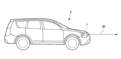
- 2 illustrates a vehicle on which the imaging system of FIG. 1 is mounted.
- 2 illustrates the operation of the imaging system of FIG. 1;
- 2 is a diagram for explaining the operation of the imaging system of FIG. 1;
- 13 illustrates a functional configuration of an imaging system according to another example.
- 6 illustrates the operation of the imaging system of FIG. 5 .
- 13 illustrates a functional configuration of an imaging system according to another example.
- 8 illustrates the operation of the imaging system of FIG. 7 .
- 8 is a diagram for explaining the operation of the imaging system of FIG. 7 .
- FIG. 1 illustrates an example of the functional configuration of an imaging system 1 according to an embodiment.
- the imaging system 1 includes an illumination device 10, an imaging element 20, and a control device 30.
- the lighting device 10 is equipped with an infrared light source 11.
- the infrared light source 11 is configured to emit infrared light IR whose central wavelength with the highest radiance when turned on is located in the infrared wavelength range.
- the infrared light source 11 can be realized by a semiconductor light-emitting element such as a light-emitting diode or a laser diode.
- radiance used in this specification does not refer to the radiance of light emitted from the light source itself, but rather to the radiance of light emitted from the lighting device 10 to the outside via an appropriate optical system.
- the image sensor 20 is sensitive to at least the infrared wavelength range and is configured to output a detection signal DT corresponding to the intensity of the incident light.
- the image sensor 20 may be of the CCD type or the CMOS type.
- the control device 30 is configured to output an illumination control signal C1 that controls the operation of the illumination device 10 and an imaging control signal C2 that controls the operation of the imaging element 20.
- the illumination control signal C1 and the imaging control signal C2 are configured to coordinate the operation of the illumination device 10 and the operation of the imaging element 20.
- the infrared light IR emitted from the infrared light source 11 can be reflected by the object OB.
- the time from when the infrared light IR is emitted from the infrared light source 11 by the illumination control signal C1 until it is incident on the image sensor 20 can be determined based on the detection signal DT.
- the distance to the object OB can be measured based on this time.
- the timing at which the image sensor 20 accepts the reflected infrared light IR can be controlled by the imaging control signal C2.
- the lighting device 10 includes a white light source 12.
- the white light source 12 is configured to emit white light W when turned on.
- the white light W is visible light.
- the white light source 12 can be realized by a semiconductor light-emitting element such as a light-emitting diode, a laser diode, or an EL element.
- the control device 30 outputs a lighting control signal C1 to turn on the white light source 12 at least when the infrared light source 11 is turned on.
- the emitted light may contain a red component.
- the emitted light from the infrared light source 11, which should be invisible, may be visible as reddish light.
- white light W is also emitted when the infrared light IR is emitted, making the reddish light less noticeable.
- the visible light switches between a state in which the red component is included and a state in which the red component is not included, causing a change in the color of the white light W.
- a change in color may cause an observer to feel uncomfortable.
- the ratio (L2/L1) of the radiance L2 of the white light W to the radiance L1 of the infrared light IR is set appropriately, based on the idea that changes in the color of the white light W can be made unnoticeable regardless of whether the infrared light source 11 is on or off, and the value of this ratio is set to 6.0E-05 or greater.
- the imaging system 1 can be mounted on a vehicle 2.
- the lighting device 10 is disposed so that the infrared light IR emitted from the infrared light source 11 is directed toward the front of the vehicle 2.
- control device 30 is configured to receive a status signal ST indicating the state of the vehicle.
- the status signal ST is transmitted from another control device mounted on the vehicle 2.
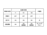
- the control device 30 outputs a lighting control signal C1 to switch the infrared light source 11 on and off based on the status signal ST. Specifically, when the status signal ST indicates that the vehicle 2 is stopped, the lighting control signal C1 is output to turn off the infrared light source 11. When the status signal ST indicates that the vehicle 2 is moving, the lighting control signal C1 is output to turn on the infrared light source 11. Figure 3 illustrates this operation.
- the lighting device 10 may include a visible light source 13.
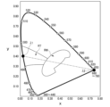
- the visible light source 13 is configured to emit visible light V of wavelength ⁇ 1 that is located in the turquoise blue color region RT in the xy chromaticity diagram of the CIE color system illustrated in FIG. 4 when lit.
- the visible light source 13 may be realized by a semiconductor light-emitting element such as a light-emitting diode, a laser diode, or an EL element.
- the wavelength ⁇ 2 in the xy chromaticity diagram corresponds to the wavelength of the red component contained in the light emitted from the infrared light source 11.
- the straight line connecting the point corresponding to the wavelength ⁇ 1 and the point corresponding to the wavelength ⁇ 2 of the turquoise blue visible light V emitted from the visible light source 13 crosses the white region RW. This fact means that by appropriately setting the radiance of the turquoise blue visible light V relative to the radiance of the red component contained in the light emitted from the infrared light source 11, it is possible to generate a white color by mixing colors.
- the control device 30 is configured to output an illumination control signal C1 that turns on the visible light source 13 when the infrared light source 11 is turned on. This produces a mixture of the red component contained in the light emitted from the infrared light source 11 and the turquoise blue of the visible light V emitted from the visible light source 13, further suppressing the change in color of the white light W emitted from the white light source 12 that accompanies the turning on of the infrared light source 11.
- Turquoise blue is recognized as a color that notifies the surroundings that the autonomous driving function is active.
- the control device 30 outputs a lighting control signal C1 that turns off the white light source 12 and increases the radiance of the visible light V emitted from the visible light source 13. As a result, it appears as if turquoise blue light is being emitted from the lighting device 10.
- the visible light source 13 which is used to make the red component contained in the light emitted from the infrared light source 11 less visible, can also be used as a light source to emit light that notifies the user that the autonomous driving function is active.
- the level of autonomous driving function that serves as the criterion for determining whether to increase the radiance of visible light V may be determined as appropriate.
- FIG. 5 shows another example of the configuration of the imaging system 1. Components that are substantially the same as those in the example described with reference to FIG. 1 are given the same reference numerals, and repeated explanations will be omitted.
- the illumination device 10 in this example includes an infrared light source 11 and a visible light source 13.
- the visible light source 13 is configured to emit visible light V of wavelength ⁇ 1 that is located in the turquoise blue color region RT in the xy chromaticity diagram of the CIE color system shown in FIG. 4 when lit.
- the visible light source 13 can be realized by a semiconductor light-emitting element such as a light-emitting diode, a laser diode, or an EL element.
- the control device 30 is configured to output an illumination control signal C1 that turns on the visible light source 13 when the infrared light source 11 is turned on.
- a straight line connecting a point corresponding to the wavelength ⁇ 1 of the turquoise blue visible light V emitted from the visible light source 13 and a point corresponding to the wavelength ⁇ 2 of the red component contained in the light emitted from the infrared light source 11 crosses the white region RW in the xy chromaticity diagram, so a mixture of the red component contained in the light emitted from the infrared light source 11 and the turquoise blue of the visible light V emitted from the visible light source 13 is produced.
- white light appears to be emitted from the illumination device 10
- the red component that may be contained in the infrared light IR emitted from the infrared light source 11 can be made invisible.
- the control device 30 When the status signal ST indicates that the autonomous driving function of the vehicle 2 is enabled, the control device 30 outputs a lighting control signal C1 that increases the radiance of the visible light V emitted from the visible light source 13. As a result, it appears as if turquoise blue light is being emitted from the lighting device 10.
- the visible light source 13 which is used to prevent the red component contained in the light emitted from the infrared light source 11 from being visible, can also be used as a light source to emit light that notifies the user that the autonomous driving function is active.
- FIG. 7 shows another example of the configuration of the imaging system 1. Components that are substantially the same as those in the example described with reference to FIG. 1 are given the same reference numerals, and repeated explanations will be omitted.
- the illumination device 10 in this example includes an infrared light source 11, a first visible light source 131, and a second visible light source 132.
- First visible light source 131 is configured to emit first visible light V1 whose central wavelength with the highest radiance is located in the visible wavelength range when lit.
- Second visible light source 132 is configured to emit second visible light V2 whose central wavelength with the highest radiance is located in the visible wavelength range when lit.
- first visible light source 131 and second visible light source 132 can be realized by a semiconductor light emitting element such as a light emitting diode, a laser diode, or an EL element.
- control device 30 is configured to output an illumination control signal C1 that turns on the first visible light source 131 and the second visible light source 132 when the infrared light source 11 is turned on.
- the wavelength ⁇ 3 in the xy chromaticity diagram of the CIE color system illustrated in FIG. 9 corresponds to the wavelength of the red component contained in the light emitted from the infrared light source 11.
- a triangle with vertices corresponding to the central wavelength ⁇ 1 of the first visible light V1, the central wavelength ⁇ 2 of the second visible light V2, and the wavelength ⁇ 3 encloses the white region RW in the xy chromaticity diagram. This fact means that by appropriately setting the radiance of the first visible light V1 and the radiance of the second visible light V2 relative to the radiance of the red component contained in the light emitted from the infrared light source 11, it is possible to generate white by mixing colors.
- the color of the first visible light V1 and the color of the second visible light V2 are mixed with a red component, which increases the range of white colors that can be generated while increasing the freedom to select the wavelength of each visible light.
- the control device 30 when the status signal ST indicates that the autonomous driving function of the vehicle 2 is enabled, the control device 30 outputs an illumination control signal C1 that increases the radiance of the first visible light V1 emitted from the first visible light source 131 and the radiance of the second visible light V2 emitted from the second visible light source 132. As a result, it appears as if turquoise blue light is being emitted from the illumination device 10.
- the first visible light source 131 and the second visible light source 132 which are used to prevent the red component contained in the light emitted from the infrared light source 11 from being visible, can also be used as a light source for emitting light that notifies the user that the autonomous driving function is active.
- the control device 30 having the various functions described so far can be realized by a general-purpose microprocessor that operates in cooperation with a general-purpose memory.
- Examples of the general-purpose microprocessor include a CPU, an MPU, and a GPU.
- Examples of the general-purpose memory include a ROM and a RAM.
- a computer program that realizes the function can be stored in the ROM.
- the general-purpose microprocessor specifies at least a portion of the program stored in the ROM and deploys it on the RAM, and works with the RAM to execute the above-mentioned processing.
- the computer program can be pre-installed in the general-purpose memory, or can be downloaded from an external server device via a communication network and then installed in the general-purpose memory.
- the control device 30 may be realized by a dedicated integrated circuit such as a microcontroller, ASIC, or FPGA capable of executing the above computer program. In this case, the above computer program is pre-installed in a memory element included in the dedicated integrated circuit.
- the control device 30 may also be realized by a combination of a general-purpose microprocessor and a dedicated integrated circuit.
- the advantages of mounting the imaging system 1 on the vehicle 2 so that the infrared light IR is emitted forward are as described above.
- the emission direction of the infrared light IR can be appropriately determined depending on the positional relationship between the object to be imaged and the vehicle 2.
- the shape of the vehicle 2 illustrated in FIG. 2 is merely an example. As long as the vehicle 2 is capable of running on a road, the shape and number of wheels of the vehicle 2 on which the imaging system 1 is mounted can be determined as appropriate.
- the imaging system 1 does not necessarily need to be mounted on the vehicle 2.
- the imaging system 1 may be installed at a fixed point to capture images using infrared light.
Landscapes
- Engineering & Computer Science (AREA)
- Mechanical Engineering (AREA)
- Lighting Device Outwards From Vehicle And Optical Signal (AREA)
Abstract
赤外光源(11)は、赤外光(IR)を出射する。白色光源(12)は、白色光(W)を出射する。制御装置(30)は、少なくとも赤外波長域に感度を有する撮像素子(20)と協働するように赤外光(IR)が出射されるタイミングを制御する。赤外光(IR)の放射輝度に対する白色光(W)の放射輝度の比は、6.0E-05以上である。
Description
本開示は、少なくとも赤外波長域に感度を有する撮像素子と協働する照明装置に関連する。本開示は、当該照明装置と当該撮像素子を含む撮像システムにも関連する。
特許文献1は、赤外光を出射可能な光源と撮像素子が協働するシステムの一例としてTOF(Time of Flight)カメラシステムを開示している。当該システムにおいては、赤外光が光源から出射されてから物体に反射されて撮像素子に検出されるまでの時間に基づいて当該物体までの距離が特定され、距離情報を含んだ画像が取得される。
赤外光源から出射される光に含まれうる赤色成分が視認されないようにすることが求められている。
本開示により提供される第一の態様例は、照明装置であって、
赤外光を出射可能な赤外光源と、
白色光を出射可能な白色光源と、
少なくとも赤外波長域に感度を有する撮像素子と協働するように前記赤外光が出射されるタイミングを制御する制御装置と、
を備えており、
前記赤外光の放射輝度に対する前記白色光の放射輝度の比は、6.0E-05以上である。
赤外光を出射可能な赤外光源と、
白色光を出射可能な白色光源と、
少なくとも赤外波長域に感度を有する撮像素子と協働するように前記赤外光が出射されるタイミングを制御する制御装置と、
を備えており、
前記赤外光の放射輝度に対する前記白色光の放射輝度の比は、6.0E-05以上である。
赤外光源の仕様としての発光スペクトル分布によっては、出射光に赤色成分が含まれうる。この場合、本来は不可視であるべき赤外光源からの出射光が、赤味を帯びた光として視認されうる。第一の態様例に係る照明装置においては、赤外光の出射時において白色光を併せて出射することにより、赤味を帯びた光を目立たなくしている。
他方、白色光源が点灯された状態で赤外光源が点消灯されると、視認される光に赤色成分が含まれる状態と含まれない状態とが切り替わるので、白色光の色味が変化する。このような色味の変化は、観察者に違和感をもたらしうる。
第一の態様例に係る照明装置においては、可視光の放射輝度に対する白色光の放射輝度の比を適切に設定すれば赤外光源の点消灯状態に依らず白色光の色味の変化を認識不能にできるとの着想に基づき、当該比の値が6.0E-05以上になるように定められている。これにより、赤色成分を目立たなくするために白色光源から出射される白色光の色味が赤外光源の点消灯に伴って変化しないようにできる。よって、当該変化に起因する違和感の発生を回避できる。
本開示により提供される第二の態様例は、照明装置であって、
赤外光を出射可能な赤外光源と、
可視光を出射可能な可視光源と、
少なくとも赤外波長域に感度を有する撮像素子と協働するように前記赤外光が出射されるタイミングを制御する制御装置と、
を備えており、
CIE表色系のxy色度図における前記可視光の波長に対応する第一の点と前記赤外光に含まれる赤色成分の波長に対応する第二の点とを結ぶ直線は、当該xy色度図における白色領域を横切っている。
赤外光を出射可能な赤外光源と、
可視光を出射可能な可視光源と、
少なくとも赤外波長域に感度を有する撮像素子と協働するように前記赤外光が出射されるタイミングを制御する制御装置と、
を備えており、
CIE表色系のxy色度図における前記可視光の波長に対応する第一の点と前記赤外光に含まれる赤色成分の波長に対応する第二の点とを結ぶ直線は、当該xy色度図における白色領域を横切っている。
第一の点と第二の点を結ぶ直線がxy色度図における白色領域を横切っている事実は、赤外光源から出射される光に含まれる赤色成分の放射輝度に対する可視光源から出射される可視光の放射輝度を適宜に設定することにより、混色による白色を生成できることを意味する。
第二の態様例に係る照明装置においては、赤外光源の点灯時において可視光源を点灯させることにより、赤外光源から出射される光に含まれる赤色成分と可視光の色の混色が生じる。結果として、照明装置からは白色の光が出射されているように見え、赤外光源から出射される光に含まれうる赤色成分が視認されないようにできる。
本開示により提供される第三の態様例は、照明装置であって、
赤外光を出射可能な赤外光源と、
可視波長域の第一波長を含む第一可視光を出射可能な第一可視光源と、
可視波長域の第二波長を含む第二可視光を出射可能な第二可視光源と、
少なくとも赤外波長域に感度を有する撮像素子と協働するように前記赤外光が出射されるタイミングを制御する制御装置と、
を備えており、
CIE表色系のxy色度図において前記第一波長に対応する第一の点、前記第二波長に対応する第二の点、および前記赤外光に含まれる赤色成分の波長に対応する第三の点を頂点とする三角形は、当該xy色度図における白色領域を囲んでいる。
赤外光を出射可能な赤外光源と、
可視波長域の第一波長を含む第一可視光を出射可能な第一可視光源と、
可視波長域の第二波長を含む第二可視光を出射可能な第二可視光源と、
少なくとも赤外波長域に感度を有する撮像素子と協働するように前記赤外光が出射されるタイミングを制御する制御装置と、
を備えており、
CIE表色系のxy色度図において前記第一波長に対応する第一の点、前記第二波長に対応する第二の点、および前記赤外光に含まれる赤色成分の波長に対応する第三の点を頂点とする三角形は、当該xy色度図における白色領域を囲んでいる。
第一波長に対応する点、第二波長に対応する点、および赤色成分の波長に対応する点を頂点とする三角形がxy色度図における白色領域を囲んでいる事実は、赤外光源から出射される光に含まれる赤色成分の放射輝度に対する第一可視光の放射輝度と第二可視光の放射輝度を適宜に設定することにより、混色による白色を生成できることを意味する。
第三の態様例に係る照明装置においては、赤外光源の点灯時において第一可視光源と第二可視光源を点灯させることにより、赤外光源から出射される光に含まれる赤色成分、第一可視光の色、および第二可視光の色の混色が生じる。結果として、照明装置からは白色の光が出射されているように見え、赤外光源から出射される光に含まれうる赤色成分が視認されないようにできる。
本開示により提供される第四の態様例は、撮像システムであって、
第一の態様例から第三の態様例の各々に係る照明装置と、
少なくとも赤外波長域に感度を有する撮像素子と、
を備えている。
第一の態様例から第三の態様例の各々に係る照明装置と、
少なくとも赤外波長域に感度を有する撮像素子と、
を備えている。
添付の図面を参照しつつ、実施形態の例について以下詳細に説明する。以下の説明に用いられる各図面では、各要素を認識可能な大きさとするために、必要に応じてその縮尺を変更している。
図1は、一実施形態例に係る撮像システム1の機能構成を例示している。撮像システム1は、照明装置10、撮像素子20、および制御装置30を含んでいる。
照明装置10は、赤外光源11を備えている。赤外光源11は、点灯時において放射輝度が最も高い中心波長が赤外波長域に位置する赤外光IRを出射可能に構成されている。赤外光源11は、発光ダイオード、レーザダイオードなどの半導体発光素子により実現されうる。
なお本明細書で用いられる「放射輝度」という語は、光源そのものから出射される光の放射輝度ではなく、適宜の光学系を介して照明装置10から外部へ出射される光の放射輝度を意味する。
撮像素子20は、少なくとも赤外波長域に感度を有し、入射した光の強度に対応する検出信号DTを出力するように構成されている。撮像素子20は、CCD方式であってもよいし、CMOS方式であってもよい。
制御装置30は、照明装置10の動作を制御する照明制御信号C1と撮像素子20の動作を制御する撮像制御信号C2を出力するように構成されている。照明制御信号C1と撮像制御信号C2は、照明装置10の動作と撮像素子20の動作を協働させるように構成される。
赤外光源11から出射された赤外光IRは、物体OBにより反射されうる。例えば、照明制御信号C1により赤外光源11から赤外光IRが出射されてから撮像素子20に入射するまでの時間が、検出信号DTに基づいて特定されうる。当該時間に基づいて物体OBまでの距離が測定されうる。撮像素子20が反射された赤外光IRの入射を受け付けるタイミングは、撮像制御信号C2により制御されうる。
照明装置10は、白色光源12を備えている。白色光源12は、点灯時において白色光Wを出射可能に構成されている。白色光Wは、可視光である。白色光源12は、発光ダイオード、レーザダイオード、EL素子などの半導体発光素子により実現されうる。
制御装置30は、少なくとも赤外光源11の点灯時において白色光源12を点灯させるように照明制御信号C1を出力する。
赤外光源11の仕様としての発光スペクトル分布によっては、出射光に赤色成分が含まれうる。この場合、本来は不可視であるべき赤外光源11からの出射光が、赤味を帯びた光として視認されうる。本実施形態例に係る構成においては、赤外光IRの出射時において白色光Wを併せて出射することにより、赤味を帯びた光を目立たなくしている。
他方、白色光源12が点灯された状態で赤外光源11が点消灯されると、視認される光に赤色成分が含まれる状態と含まれない状態とが切り替わるので、白色光Wの色味が変化する。このような色味の変化は、観察者に違和感をもたらしうる。
本実施形態例においては、赤外光IRの放射輝度L1に対する白色光Wの放射輝度L2の比(L2/L1)を適切に設定すれば赤外光源11の点消灯状態に依らず白色光Wの色味の変化を認識不能にできるとの着想に基づき、当該比の値が6.0E-05以上になるように定められている。
これにより、赤色成分を目立たなくするために白色光源12から出射される白色光Wの色味が赤外光源11の点消灯に伴って変化しないようにできる。よって、当該変化に起因する違和感の発生を回避できる。
図2に例示されるように、撮像システム1は、車両2に搭載されうる。本例においては、赤外光源11から出射された赤外光IRが車両2の前方へ向かうように照明装置10が配置されている。
車両の前方に赤色光を出射することが法規で禁止されている地域が存在する。上記の構成によれば、車両2の前方に出射される光に含まれる赤色成分が視認されないようにできるので、当該法規を満足できる点において特に有利である。
本例においては、図1に例示されるように、制御装置30が車両の状態を示すステータス信号STを受け付けるように構成されている。ステータス信号STは、車両2に搭載された他の制御装置から送信される。
制御装置30は、ステータス信号STに基づいて赤外光源11の点消灯を切り替えるように照明制御信号C1を出力する。具体的には、車両2が停車中であることをステータス信号STが示している場合、赤外光源11を消灯させる照明制御信号C1が出力される。車両2が走行中であることをステータス信号STが示している場合、赤外光源11を点灯させる照明制御信号C1が出力される。図3は、この動作を例示している。
停車中の車両の前方に赤外光を出射することが法規で禁止されている地域が存在する。上記の動作はこの法規を満足するためになされる。前述した赤外光IRの放射輝度に対する白色光Wの放射輝度の比に係る構成によれば、このようにして車両2の停車時と走行時で赤外光源11の点消灯が切り替えられても、観察者が白色光Wの色味の変化を認識できないようにできる。よって、当該構成は、当該法規を満足しつつ色味の変化に起因する違和感の発生も回避できる点において特に有利である。
図1に例示されるように、照明装置10は、可視光源13を備えうる。可視光源13は、点灯時において図4に例示されるCIE表色系のxy色度図におけるターコイズブルー色領域RTに位置する波長λ1の可視光Vを出射可能に構成されている。可視光源13は、発光ダイオード、レーザダイオード、EL素子などの半導体発光素子により実現されうる。
xy色度図における波長λ2は、赤外光源11から出射される光に含まれる赤色成分の波長に対応している。可視光源13から出射されるターコイズブルーの可視光Vの波長λ1に対応する点と波長λ2に対応する点とを結ぶ直線は、白色領域RWを横切っている。当該事実は、赤外光源11から出射される光に含まれる赤色成分の放射輝度に対するターコイズブルーの可視光Vの放射輝度を適宜に設定することにより、混色による白色を生成できることを意味する。
図3に例示されるように、制御装置30は、赤外光源11の点灯時において可視光源13を点灯させる照明制御信号C1を出力するように構成される。これにより、赤外光源11から出射される光に含まれる赤色成分と可視光源13から出射される可視光Vのターコイズブルーの混色が生じ、白色光源12から出射される白色光Wの赤外光源11の点灯に伴う色味の変化をさらに抑制できる。
ターコイズブルーは、自動運転機能が有効であることを周囲に報知するための色として認知されている。制御装置30は、車両2の自動運転機能が有効とされていることをステータス信号STが示している場合、白色光源12を消灯させ、かつ可視光源13から出射される可視光Vの放射輝度を高める照明制御信号C1を出力する。結果として、照明装置10からはターコイズブルーの光が出射されているように見える。
このような構成によれば、赤外光源11から出射された光に含まれる赤色成分が視認されにくくするために使用される可視光源13を、自動運転機能が有効であることを報知する光を出射するための光源としても利用できる。
なお、可視光Vの放射輝度を高める判断の基準となる自動運転機能のレベルについては、適宜に定められうる。
図5は、撮像システム1の構成の別例を示している。図1を参照して説明した例と実質的に同一の構成要素には同一の参照符号を付与し、繰り返しとなる説明は省略する。本例に係る照明装置10は、赤外光源11と可視光源13を備えている。
可視光源13は、点灯時において図4に例示されるCIE表色系のxy色度図におけるターコイズブルー色領域RTに位置する波長λ1の可視光Vを出射可能に構成されている。可視光源13は、発光ダイオード、レーザダイオード、EL素子などの半導体発光素子により実現されうる。
図6に例示されるように、制御装置30は、赤外光源11の点灯時において可視光源13を点灯させる照明制御信号C1を出力するように構成される。可視光源13から出射されるターコイズブルーの可視光Vの波長λ1に対応する点と赤外光源11から出射される光に含まれる赤色成分の波長λ2に対応する点とを結ぶ直線は、xy色度図における白色領域RWを横切っているので、赤外光源11から出射される光に含まれる赤色成分と可視光源13から出射される可視光Vのターコイズブルーの混色が生じる。結果として、照明装置10からは白色の光が出射されているように見え、赤外光源11から出射される赤外光IRに含まれうる赤色成分が視認されないようにできる。
制御装置30は、車両2の自動運転機能が有効とされていることをステータス信号STが示している場合、可視光源13から出射される可視光Vの放射輝度を高める照明制御信号C1を出力する。結果として、照明装置10からはターコイズブルーの光が出射されているように見える。
このような構成によれば、赤外光源11から出射された光に含まれる赤色成分が視認されないようにするために使用される可視光源13を、自動運転機能が有効であることを報知する光を出射するための光源としても利用できる。
図7は、撮像システム1の構成の別例を示している。図1を参照して説明した例と実質的に同一の構成要素には同一の参照符号を付与し、繰り返しとなる説明は省略する。本例に係る照明装置10は、赤外光源11、第一可視光源131、および第二可視光源132を備えている。
第一可視光源131は、点灯時において放射輝度が最も高い中心波長が可視波長域に位置する第一可視光V1を出射可能に構成されている。第二可視光源132は、点灯時において放射輝度が最も高い中心波長が可視波長域に位置する第二可視光V2を出射可能に構成されている。第一可視光源131と第二可視光源132の各々は、発光ダイオード、レーザダイオード、EL素子などの半導体発光素子により実現されうる。
図8に例示されるように、制御装置30は、赤外光源11の点灯時において第一可視光源131と第二可視光源132を点灯させる照明制御信号C1を出力するように構成される。
図9に例示されるCIE表色系のxy色度図における波長λ3は、赤外光源11から出射される光に含まれる赤色成分の波長に対応している。第一可視光V1の中心波長λ1に対応する点、第二可視光V2の中心波長λ2に対応する点、および波長λ3に対応する点を頂点とする三角形は、xy色度図における白色領域RWを囲んでいる。当該事実は、赤外光源11から出射される光に含まれる赤色成分の放射輝度に対する第一可視光V1の放射輝度と第二可視光V2の放射輝度を適宜に設定することにより、混色による白色を生成できることを意味する。
すなわち、赤外光源11の点灯時において第一可視光源131と第二可視光源132を点灯させることにより、赤外光源11から出射される光に含まれる赤色成分、第一可視光V1の色、および第二可視光V2の色の混色が生じる。結果として、照明装置10からは白色の光が出射されているように見え、赤外光源11から出射される光に含まれうる赤色成分が視認されないようにできる。
加えて、第一可視光V1の色と第二可視光V2の色を赤色成分と混色させるので、生成可能な白色の範囲を広げつつ、各可視光の波長の選択自由度を高めることができる。
第一可視光源131から出射される第一可視光V1の中心波長λ1に対応する点と第二可視光源132から出射される第二可視光V2の中心波長λ2に対応する点とを結ぶ直線は、xy色度図におけるターコイズブルー色領域RTを横切っている。当該事実は、第一可視光V1の放射輝度と第二可視光V2の放射輝度を適宜に設定することにより、混色によりターコイズブルーを生成できることを意味する。
図8に例示されるように、制御装置30は、車両2の自動運転機能が有効とされていることをステータス信号STが示している場合、第一可視光源131から出射される第一可視光V1の放射輝度と第二可視光源132から出射される第二可視光V2の放射輝度を高める照明制御信号C1を出力する。結果として、照明装置10からはターコイズブルーの光が出射されているように見える。
このような構成によれば、赤外光源11から出射された光に含まれる赤色成分が視認されないようにするために使用される第一可視光源131と第二可視光源132を、自動運転機能が有効であることを報知する光を出射するための光源としても利用できる。
これまで説明した各種の機能を有する制御装置30は、汎用メモリと協働して動作する汎用マイクロプロセッサにより実現されうる。汎用マイクロプロセッサとしては、CPU、MPU、GPUが例示されうる。汎用メモリとしては、ROMやRAMが例示されうる。この場合、ROMには、当該機能を実現するコンピュータプログラムが記憶されうる。汎用マイクロプロセッサは、ROM上に記憶されたプログラムの少なくとも一部を指定してRAM上に展開し、RAMと協働して上述した処理を実行する。当該コンピュータプログラムは、汎用メモリにプリインストールされてもよいし、通信ネットワークを介して外部サーバ装置からダウンロードされてから汎用メモリにインストールされてもよい。
制御装置30は、上記のコンピュータプログラムを実行可能なマイクロコントローラ、ASIC、FPGAなどの専用集積回路によって実現されてもよい。この場合、当該専用集積回路に含まれる記憶素子に上記のコンピュータプログラムがプリインストールされる。制御装置30は、汎用マイクロプロセッサと専用集積回路の組合せによっても実現されうる。
これまで説明した様々な構成は、本開示の理解を容易にするための例示にすぎない。各構成例は、本開示の趣旨の範囲内で適宜に変更や相互の組合せがなされうる。
赤外光IRが前方へ出射されるように撮像システム1が車両2に搭載される場合の有利性については、前述の通りである。しかしながら、撮像を希望する物体と車両2との位置関係に応じて、赤外光IRの出射方向は適宜に定められうる。
図2に例示された車両2の形状は、例示に過ぎない。道路を走行可能であれば、撮像システム1が搭載される車両2の形状および車輪の数は、適宜に定められうる。
撮像システム1は、必ずしも車両2に搭載されることを要しない。撮像システム1は、赤外光を用いた撮像を行なうために定点に設置されてもよい。
本開示の一部を構成するものとして、2023年7月5日付にて提出された日本国特許出願2023-110741号の内容が援用される。
Claims (10)
- 赤外光を出射可能な赤外光源と、
白色光を出射可能な白色光源と、
少なくとも赤外波長域に感度を有する撮像素子と協働するように前記赤外光が出射されるタイミングを制御する制御装置と、
を備えており、
前記赤外光の放射輝度に対する前記白色光の放射輝度の比は、6.0E-05以上である、
照明装置。 - 前記赤外光が前方へ出射されるように車両に搭載される、
請求項1に記載の照明装置。 - CIE表色系のxy色度図においてターコイズブルー色領域に位置する波長の可視光を出射可能な可視光源を備えており、
前記制御装置は、前記車両の走行時に前記可視光源に前記可視光を出射させ、かつ前記車両において自動運転機能が有効とされている場合に前記可視光の放射輝度を高める、
請求項2に記載の照明装置。 - 赤外光を出射可能な赤外光源と、
可視光を出射可能な可視光源と、
少なくとも赤外波長域に感度を有する撮像素子と協働するように前記赤外光が出射されるタイミングを制御する制御装置と、
を備えており、
CIE表色系のxy色度図における前記可視光の波長に対応する第一の点と前記赤外光に含まれる赤色成分の波長に対応する第二の点とを結ぶ直線は、当該xy色度図における白色領域を横切っている、
照明装置。 - 前記赤外光が前方へ出射されるように車両に搭載される、
請求項4に記載の照明装置。 - 前記第一の点は、前記xy色度図におけるターコイズブルー色領域に位置しており、
前記制御装置は、前記車両において自動運転機能が有効とされている場合に前記可視光の放射輝度を高める、
請求項5に記載の照明装置。 - 赤外光を出射可能な赤外光源と、
可視波長域の第一波長を含む第一可視光を出射可能な第一可視光源と、
可視波長域の第二波長を含む第二可視光を出射可能な第二可視光源と、
少なくとも赤外波長域に感度を有する撮像素子と協働するように前記赤外光が出射されるタイミングを制御する制御装置と、
を備えており、
CIE表色系のxy色度図において前記第一波長に対応する第一の点、前記第二波長に対応する第二の点、および前記赤外光に含まれる赤色成分の波長に対応する第三の点を頂点とする三角形は、当該xy色度図における白色領域を囲んでいる、
照明装置。 - 前記赤外光が前方へ出射されるように車両に搭載される、
請求項7に記載の照明装置。 - 前記第一の点と前記第二の点とを結ぶ直線は、前記xy色度図におけるターコイズブルー色領域を横切っており、
前記制御装置は、前記車両において自動運転機能が有効とされている場合に前記第一可視光と前記第二可視光の放射輝度を高める、
請求項8に記載の照明装置。 - 請求項1から9のいずれか一項に記載の照明装置と、
少なくとも赤外波長域に感度を有する撮像素子と、
を備えている、
撮像システム。
Priority Applications (1)
| Application Number | Priority Date | Filing Date | Title |
|---|---|---|---|
| JP2025531579A JPWO2025009559A1 (ja) | 2023-07-05 | 2024-07-03 |
Applications Claiming Priority (2)
| Application Number | Priority Date | Filing Date | Title |
|---|---|---|---|
| JP2023-110741 | 2023-07-05 | ||
| JP2023110741 | 2023-07-05 |
Publications (1)
| Publication Number | Publication Date |
|---|---|
| WO2025009559A1 true WO2025009559A1 (ja) | 2025-01-09 |
Family
ID=94171738
Family Applications (1)
| Application Number | Title | Priority Date | Filing Date |
|---|---|---|---|
| PCT/JP2024/024092 Ceased WO2025009559A1 (ja) | 2023-07-05 | 2024-07-03 | 照明装置、および撮像システム |
Country Status (2)
| Country | Link |
|---|---|
| JP (1) | JPWO2025009559A1 (ja) |
| WO (1) | WO2025009559A1 (ja) |
Citations (6)
| Publication number | Priority date | Publication date | Assignee | Title |
|---|---|---|---|---|
| JP2005112235A (ja) * | 2003-10-09 | 2005-04-28 | Ichikoh Ind Ltd | 車両周辺暗視用灯具および車両用アウトサイドミラー装置 |
| JP2006066397A (ja) * | 2004-08-27 | 2006-03-09 | Schott Ag | ナイトビジョンヘッドランプ |
| JP2006137367A (ja) * | 2004-11-15 | 2006-06-01 | Koito Mfg Co Ltd | 車両用赤外線投光器 |
| JP2006332288A (ja) * | 2005-05-25 | 2006-12-07 | Stanley Electric Co Ltd | 車載監視カメラの照明用led光源 |
| JP2010137729A (ja) * | 2008-12-12 | 2010-06-24 | Stanley Electric Co Ltd | 車両用赤外投光器 |
| WO2020116239A1 (ja) * | 2018-12-04 | 2020-06-11 | 株式会社小糸製作所 | 赤外線カメラシステム及び車両 |
-
2024
- 2024-07-03 WO PCT/JP2024/024092 patent/WO2025009559A1/ja not_active Ceased
- 2024-07-03 JP JP2025531579A patent/JPWO2025009559A1/ja active Pending
Patent Citations (6)
| Publication number | Priority date | Publication date | Assignee | Title |
|---|---|---|---|---|
| JP2005112235A (ja) * | 2003-10-09 | 2005-04-28 | Ichikoh Ind Ltd | 車両周辺暗視用灯具および車両用アウトサイドミラー装置 |
| JP2006066397A (ja) * | 2004-08-27 | 2006-03-09 | Schott Ag | ナイトビジョンヘッドランプ |
| JP2006137367A (ja) * | 2004-11-15 | 2006-06-01 | Koito Mfg Co Ltd | 車両用赤外線投光器 |
| JP2006332288A (ja) * | 2005-05-25 | 2006-12-07 | Stanley Electric Co Ltd | 車載監視カメラの照明用led光源 |
| JP2010137729A (ja) * | 2008-12-12 | 2010-06-24 | Stanley Electric Co Ltd | 車両用赤外投光器 |
| WO2020116239A1 (ja) * | 2018-12-04 | 2020-06-11 | 株式会社小糸製作所 | 赤外線カメラシステム及び車両 |
Also Published As
| Publication number | Publication date |
|---|---|
| JPWO2025009559A1 (ja) | 2025-01-09 |
Similar Documents
| Publication | Publication Date | Title |
|---|---|---|
| US6601980B2 (en) | Infrared-ray radiating lamp for automobile | |
| US10239440B2 (en) | Illumination apparatus for vehicle | |
| JP2016008043A (ja) | 車両用照明装置 | |
| US10063788B2 (en) | Night-vision image processing apparatus | |
| US11796807B2 (en) | Head-up display device and head-up display system | |
| US10179535B2 (en) | Lighting control device of vehicle headlamp and vehicle headlamp system | |
| CN110099269B (zh) | 具有可调光强度的深度产生系统 | |
| US20200200356A1 (en) | Ir illuminator with secondary function | |
| CN108302458A (zh) | 车辆用前照灯 | |
| JP6457793B2 (ja) | 標識灯 | |
| CN111108323A (zh) | 投影装置、后视设备和机动车 | |
| JP7538805B2 (ja) | 車両用ランプシステム | |
| CN111332189A (zh) | 具有静态和动态图像投影的照地灯 | |
| US20170015236A1 (en) | Vehicle lamp control system | |
| WO2025009559A1 (ja) | 照明装置、および撮像システム | |
| KR101834733B1 (ko) | 차량용 카메라 시스템 | |
| US20250153633A1 (en) | Communication lamp for vehicle | |
| JP2017105291A (ja) | ヘッドアップディスプレイ装置 | |
| JP2006332288A (ja) | 車載監視カメラの照明用led光源 | |
| WO2017134121A1 (en) | Camera system for a vehicle | |
| JP2025184753A (ja) | 車両用ランプシステム | |
| JP5803505B2 (ja) | 映像処理装置 | |
| JP6992296B2 (ja) | 車両用灯具 | |
| TWI858990B (zh) | 照明模組 | |
| US20250229700A1 (en) | Method for operating a headlight device for a vehicle, and motor vehicle having a headlight device |
Legal Events
| Date | Code | Title | Description |
|---|---|---|---|
| 121 | Ep: the epo has been informed by wipo that ep was designated in this application |
Ref document number: 24836072 Country of ref document: EP Kind code of ref document: A1 |
|
| ENP | Entry into the national phase |
Ref document number: 2025531579 Country of ref document: JP Kind code of ref document: A |
|
| WWE | Wipo information: entry into national phase |
Ref document number: 2025531579 Country of ref document: JP |
|
| NENP | Non-entry into the national phase |
Ref country code: DE |