WO2025009520A1 - 長尺物の案内装置 - Google Patents
長尺物の案内装置 Download PDFInfo
- Publication number
- WO2025009520A1 WO2025009520A1 PCT/JP2024/023900 JP2024023900W WO2025009520A1 WO 2025009520 A1 WO2025009520 A1 WO 2025009520A1 JP 2024023900 W JP2024023900 W JP 2024023900W WO 2025009520 A1 WO2025009520 A1 WO 2025009520A1
- Authority
- WO
- WIPO (PCT)
- Prior art keywords
- connecting member
- link
- engaged
- engaged portion
- pair
- Prior art date
- Legal status (The legal status is an assumption and is not a legal conclusion. Google has not performed a legal analysis and makes no representation as to the accuracy of the status listed.)
- Ceased
Links
Images





Classifications
-
- F—MECHANICAL ENGINEERING; LIGHTING; HEATING; WEAPONS; BLASTING
- F16—ENGINEERING ELEMENTS AND UNITS; GENERAL MEASURES FOR PRODUCING AND MAINTAINING EFFECTIVE FUNCTIONING OF MACHINES OR INSTALLATIONS; THERMAL INSULATION IN GENERAL
- F16G—BELTS, CABLES, OR ROPES, PREDOMINANTLY USED FOR DRIVING PURPOSES; CHAINS; FITTINGS PREDOMINANTLY USED THEREFOR
- F16G13/00—Chains
- F16G13/12—Hauling- or hoisting-chains so called ornamental chains
- F16G13/16—Hauling- or hoisting-chains so called ornamental chains with arrangements for holding electric cables, hoses, or the like
-
- F—MECHANICAL ENGINEERING; LIGHTING; HEATING; WEAPONS; BLASTING
- F16—ENGINEERING ELEMENTS AND UNITS; GENERAL MEASURES FOR PRODUCING AND MAINTAINING EFFECTIVE FUNCTIONING OF MACHINES OR INSTALLATIONS; THERMAL INSULATION IN GENERAL
- F16L—PIPES; JOINTS OR FITTINGS FOR PIPES; SUPPORTS FOR PIPES, CABLES OR PROTECTIVE TUBING; MEANS FOR THERMAL INSULATION IN GENERAL
- F16L3/00—Supports for pipes, cables or protective tubing, e.g. hangers, holders, clamps, cleats, clips, brackets
- F16L3/01—Supports for pipes, cables or protective tubing, e.g. hangers, holders, clamps, cleats, clips, brackets for supporting or guiding the pipes, cables or protective tubing, between relatively movable points, e.g. movable channels
-
- H—ELECTRICITY
- H02—GENERATION; CONVERSION OR DISTRIBUTION OF ELECTRIC POWER
- H02G—INSTALLATION OF ELECTRIC CABLES OR LINES, OR OF COMBINED OPTICAL AND ELECTRIC CABLES OR LINES
- H02G3/00—Installations of electric cables or lines or protective tubing therefor in or on buildings, equivalent structures or vehicles
- H02G3/02—Details
- H02G3/04—Protective tubing or conduits, e.g. cable ladders or cable troughs
Definitions
- This disclosure relates to a guide device for long objects.
- the pair of link plates 81 have an engagement piece at their upper ends that engages with the retaining plate 84.
- the engagement piece is composed of a semicircular rod body 85 with a circumferential surface on the inner side of the pair of link plates 81.
- the outer side of the rod body 85 is a flat surface 85a, and this flat surface 85a has a groove 85b that runs along the axial direction of the link 83.
- the retaining plate 84 has a base plate 86, a first side piece 87 that hangs down from one end of the base plate 86, and a second side piece 88 that hangs down from the other end of the base plate 86.
- the first side piece 87 has a protrusion 87a that engages with a groove 85b in the rod body 85.
- the second side piece 88 has a semicircular locking hole 88a that fits into the rod body 85.
- the rod 85 of one link plate 81 is fitted into the semicircular locking hole 88a of the second side piece 88 of the retaining plate 84.
- the retaining plate 84 is then rotated around the semicircular locking hole 88a.
- the retaining plate 84 is attached to the pair of link plates 81 by engaging the protrusion 87a of the first side piece 87 of the retaining plate 84 with the groove 85b of the rod body 85 of the other link plate 81.
- the engagement between the retaining plate 84 as the first connecting member and the link plate 81 may be released in order to inspect or replace the long object.
- an operator inserts a tool or the like between the first side piece 87 of the retaining plate 84 and the rod body 85 of the other link plate 81 to release the engagement between the protrusion 87a of the first side piece 87 and the groove 85b of the rod body 85.
- a guide device for long objects includes a plurality of links connected in series so as to be freely rotatable with respect to each other, each link including a pair of opposing link plates, a first connecting member connecting the pair of link plates, and a second connecting member connecting the pair of link plates, and is configured so that a long object is accommodated within a space surrounded by the pair of link plates, the first connecting member, and the second connecting member in each link, and one of the pair of link plates in each link includes a first engaged portion and the other includes a second engaged portion, and in each link
- the first connecting member has a plate-shaped main body, a first engaging portion that engages with the first engaged portion, and a second engaging portion that engages with the second engaged portion.
- At least one of the first engaged portion and the second engaged portion has an outer engaged portion
- at least one of the first engaging portion and the second engaging portion has a hanging wall extending in the thickness direction of the main body, an inner engaging portion provided on the hanging wall that engages with the outer engaged portion, and an outer protruding wall that protrudes outward beyond the hanging wall.
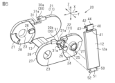
- FIG. 1 is a perspective view of a guiding device for an elongated object according to an embodiment
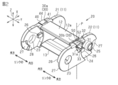
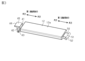
- FIG. FIG. FIG. 11 is a perspective view of the first connecting member from a different angle
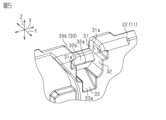
- 13 is a perspective view of a second engaged portion of the link plate.
- FIG. FIG. 11 is a cross-sectional view showing a state in which a hinge shaft is engaged with a hinge bearing portion.
- FIG. 13 is a perspective view of an outer engaged portion of the first engaged portion of the link plate and an inner engaging portion of the first engaging portion of the first connecting member before they are engaged with each other.
- FIG. 13 is a perspective view of a state in which an outer engaged portion of the first engaged portion of the link plate and an inner engaging portion of the first engaging portion of the first connecting member are engaged with each other.
- FIG. 13 is a partial cross-sectional view of an outer engaged portion of the first engaged portion of the link plate and an inner engaging portion of the first engaging portion of the first connecting member before engagement between the outer engaged portion and the first engaged portion of the link plate.
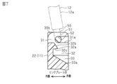
- FIG. 11 is a partial cross-sectional view showing a state in which the outer engaged portion and the inner engaging portion are engaged with each other.
- FIG. 13 is a partial cross-sectional view showing a state in which an outer engaged portion and an inner engaging portion of a modified example are engaged with each other.
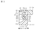
- FIG. FIG. 11 is a partial cross-sectional view of another modified example in which an outer engaged portion and an inner engaging portion are engaged with each other.
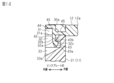
- FIG. 11 is a partial cross-sectional view of yet another modified example in which an outer engaged portion and an inner engaging portion are engaged with each other.
- FIG. 1 is a cross-sectional view of a conventional long object guiding device.
- a guide device 10 for a long object (hereinafter also referred to as a guide device) 10 includes a plurality of links 20.
- Each link 20 includes a pair of opposing link plates 11, a first connecting member 12 connecting the pair of link plates 11, and a second connecting member 13 connecting the pair of link plates 11.
- the plurality of links 20 are connected in series so as to be rotatable relative to one another.
- serial direction X A direction perpendicular to the serial direction X and in which the pair of link plates 11 face each other is referred to as a width direction Y.
- a direction perpendicular to both the serial direction X and the width direction Y is defined as an up-down direction Z based on a point where the multiple links 20 extend linearly.
- the link 20 located at one end in the serial direction X has a connecting fitting 14.
- the connecting fitting 14 is connected to a moving body (not shown) that moves back and forth in the serial direction X.
- the link 20 located at the other end in the serial direction X has a fixing fitting 15.
- the fixing fitting 15 is fixed to a fixing portion (not shown).
- the direction connected to the connecting fitting 14 is the front, and the direction fixed to the fixing fitting 15 is the rear.
- the direction in which the pair of link plates 11 face each other is the inside of the link 20, and the opposite direction is the outside of the link 20.
- the link plate 11 located at the back side of FIG. 2 may be referred to as the first link plate 21.
- the link plate 11 located at the front side of FIG. 2 may be referred to as the second link plate 22.
- the guide device 10 accommodates a long object TK in a space surrounded by a pair of link plates 11, a first connecting member 12, and a second connecting member 13 in each link 20.
- the long object TK can be bent flexibly.
- the guide device 10 accommodates the long object TK in the space and guides the long object TK while protecting it with the multiple links 20.
- the link plate 11 is configured as a long plate in the serial direction X. Both ends of the link plate 11 in the serial direction X are semicircular with both outer sides in the serial direction X being convex.
- the link plate 11 has an engaged portion 30 at an upper end in the up-down direction Z in a central portion in the serial direction X, with which the first connecting member 12 engages.
- the engaged portion 30 will be described later.
- the link plate 11 has an engaged portion at the lower end in the up-down direction Z at the center of the serial direction X, with which the second connecting member 13 engages. A description of this engaged portion will be omitted.
- the second connecting member 13 is connected to both of the pair of link plates 11.
- the second connecting member 13 connects the lower ends of the pair of link plates 11 to each other.
- the second link plate 22 of the pair of link plates 11 will be described.
- the second link plate 22 has a through hole 23 forward of the center in the serial direction X.
- the second link plate 22 has an outer thin portion 24 rearward of the center in the serial direction X, the outer thin portion 24 having a thickness that decreases from the outside to the inside of the second link plate 22.
- the front edge of the outer thin portion 24 has a curved shape that is convex forward.
- the second link plate 22 has a cylindrical shaft portion 25 that protrudes outward from the center of the outer thin portion 24.
- the protruding height of the shaft portion 25 is approximately equal to the depth of the outer thin portion 24.
- the top of the shaft portion 25 is approximately the same height as the outer surface of the second link plate 22 excluding the outer thin portion 24.
- the second link plate 22 has a rectangular protrusion 26 in the outer thin portion 24, located forward of the shaft portion 25. Also, behind the shaft portion 25, the second link plate 22 has a sector-shaped recess 27 where the thickness of the second link plate 22 becomes even thinner and spreads out in a sector shape toward the rear.
- the second link plate 22 has an inner thin portion 28 that is recessed from the inside to the outside of the second link plate 22, located forward of the center portion in the serial direction X.
- the shape of the inner thin portion 28 at the center of the second link plate 22 in the serial direction X is the same as the shape of the outer thin portion 24 when the second link plate 22 is rotated 180 degrees about the rotation axis P, assuming a rotation axis P extending in the up-down direction Z. That is, the inner thin portion 28 has a rectangular convex portion 26 and a sector-shaped concave portion 27 on the inward side of the link 20, and has a through hole 23 at the position of the shaft portion 25 in the outer thin portion 24.
- the pair of link plates 11 are symmetrical.
- the pair of link plates 11 are mirror images of each other, including the shape of the engaged portion 30. That is, the first link plate 21 and the second link plate 22 are mirror images of each other in the opposing directions.
- the guide device 10 has multiple links 20 connected in series so that they can rotate freely with each other.
- the rear side of one pair of link plates 11 is connected to the front side of another pair of link plates 11.
- the shaft portion 25 located in the outer thin portion 24 of one pair of link plates 11 is fitted into the through hole 23 located in the inner thin portion 28 of the other pair of link plates 11.
- the rectangular convex portion 26 of the outer thin portion 24 is placed in the sector-shaped recess 27 of the inner thin portion 28.
- the rectangular convex portion 26 of the inner thin portion 28 is placed in the sector-shaped recess 27 of the outer thin portion 24.
- the rotation range of the other pair of link plates 11 is determined within the range in which the rectangular protrusions 26 of the other pair of link plates 11, which are arranged within the sectorial recesses 27 of the pair of link plates 11, can swing.
- the rotation range can be changed by changing the angle or direction of the sector in the sectorial recesses 27, or the shape or position of the rectangular protrusions 26.
- the link plate 11 has an engaged portion 30 with which the first connecting member 12 engages at an upper end portion at the center in the serial direction X.
- the first link plate 21 of the pair of link plates 11 has a first engaged portion 30a with which the first engaging portion 40 of the first connecting member 12 engages.
- the second link plate 22 of the pair of link plates 11 has a second engaged portion 30b with which the second engaging portion 50 of the first connecting member 12 engages.
- one of the pair of link plates 11 has the first engaged portion 30a with which the first engaging portion 40 of the first connecting member 12 engages.
- the other of the pair of link plates 11 has the second engaged portion 30b with which the second engaging portion 50 of the first connecting member 12 engages.
- the second engaged portion 30b has a first notch 31 cut downward from the upper end of the second link plate 22.
- the first notch 31 penetrates the second link plate 22 in the thickness direction.
- the depth of the first notch 31, i.e., the length of the first notch 31 in the up-down direction Z, is approximately equal to the thickness of the main body 12a of the first connecting member 12.
- the second engaged portion 30b has a hinge bearing portion 31a recessed on both sides in the serial direction X from the first notch 31.
- the hinge bearing portion 31a extends to the outer surface of the second link plate 22 in the thickness direction of the second link plate 22.
- the inner periphery of the hinge bearing portion 31a is semicircular, and the hinge shaft 52 described below can rotate while engaged with the hinge bearing portion 31a.
- the second engaged portion 30b has a second notch 32 below the first notch 31.
- the second notch 32 cuts out the outer portion of the second link plate 22 in the thickness direction of the second link plate 22.
- the width of the second notch 32 along the serial direction X is the same as the width of the first notch 31 along the same direction.
- the second engaged portion 30b has an outer convex portion 32a, which serves as an outer engaged portion and protrudes outward, on the inner side of the second cutout 32.
- the outer convex portion 32a has an inclined surface 32b that slopes diagonally downward outward.
- the outer convex portion 32a has a horizontal surface 32c that extends in the thickness direction of the second link plate 22 below the inclined surface 32b.
- the second engaged portion 30b has a third notch 33 below the second notch 32.
- the third notch 33 extends from the center of the second notch 32 in the serial direction X at an outwardly downward angle, and has an inclined surface 33a that is inclined outwardly and downwardly.
- the width of the third notch 33 along the serial direction X is shorter than the width of the second notch 32.
- the third notch 33 functions as a release recess into which a tool or finger can be inserted when removing the first engaging portion 40 of the first connecting member 12 from the engaged portion 30 of the first link plate 21.
- the first connecting member 12 has a plate-shaped main body portion 12a, a first engaging portion 40 that engages with the first engaged portion 30a of the first link plate 21, and a second engaging portion 50 that engages with the second engaged portion 30b of the second link plate 22.
- the main body 12a has a plate surface aligned in the serial direction X and extends elongatedly in the width direction Y.
- the first engagement portion 40 has a curved portion 41 extending from one longitudinal end of the main body portion 12a, a hanging wall 42 extending downward from the outer end of the curved portion 41 along the thickness direction of the main body portion 12a, and an outward protruding wall 44 protruding outward from the upper end of the hanging wall 42.
- crank-like means a shape with two or more points that are curved in opposite directions.
- the hanging wall 42 "extending downward along the thickness direction of the main body 12a" does not necessarily have to coincide completely with the thickness direction of the main body 12a, but also includes a direction that is slightly inclined relative to the thickness direction of the main body 12a.
- the first engagement portion 40 has an inward protrusion 43 that protrudes inwardly at the lower end of the hanging wall 42 and serves as an inner engagement portion.
- the inward protrusion 43 has an inclined surface 43a that is inclined diagonally upward inward.
- the inward protrusion 43 also has a parallel surface 43b above the inclined surface 43a that extends parallel to the longitudinal direction of the main body 12a.
- the protruding length of the outwardly protruding wall 44 is such that the tip of the outwardly protruding wall 44 does not protrude from the outer end of the first link plate 21 when the first engaging portion 40 is attached to the first engaged portion 30a of the first link plate 21. Specifically, the tip of the outwardly protruding wall 44 is flush with the outer end of the first link plate 21.
- the upper surface which is the outer surface of the outwardly protruding wall 44 is located lower than the upper surface which is the outer surface of the main body portion 12 a of the first connecting member 12 .
- the length of the first engagement portion 40 along the serial direction X i.e., the widths of the curved portion 41, the hanging wall 42, the inward convex portion 43, and the outward protruding wall 44 along the serial direction X, are slightly smaller than the width of the second notch 32 along the same direction.
- the second engagement portion 50 has a protruding piece 51 protruding outward from the other end of the main body portion 12a in the longitudinal direction, and a hinge shaft 52 protruding on both sides in the lateral direction of the main body portion 12a from the tip of the protruding piece 51.
- the cross section of the hinge shaft 52 is circular.
- the second connecting member 13 is made of a long plate material.
- the second connecting member 13 connects the lower ends of the pair of link plates 11.
- the second connecting member 13 is attached at a position overlapping the first connecting member 12 in the up-down direction Z.
- the hinge shaft 52 is restricted from moving further inwardly of the second link plate 22 while in contact with the semicircular periphery of the hinge bearing portion 31a. This causes the second engaging portion 50 of the first connecting member 12 to engage with the second engaged portion 30b of the second link plate 22.
- the first connecting member 12 is rotated about the hinge shaft 52 so that the first engaging portion 40 approaches the first engaged portion 30 a of the first link plate 21 .
- the first engaging portion 40 of the first connecting member 12 is inserted into the first notch 31 in the first engaged portion 30 a of the first link plate 21 .
- the inner protrusion 43 of the hanging wall 42 of the first connecting member 12 engages from the outside with the outer protrusion 32a in the second notch 32 of the first engaged portion 30a of the first link plate 21, thereby preventing the first engaging portion 40 from coming off the engaged portion 30.
- the inclined surface 32b of the outer convex portion 32a comes into contact with the inclined surface 43a of the inner convex portion 43, reducing the resistance during engagement.
- the horizontal surface 32c of the outer convex portion 32a comes into contact with the parallel surface 43b of the inner convex portion 43, making it difficult to release the engagement.
- the curved portion 41 of the first engaging portion 40 abuts against the lower end of the first notch 31 of the first engaged portion 30a. In other words, the curved portion 41 of the first engaging portion 40 abuts against the outer convex portion 32a of the second notch 32. By the curved portion 41 of the first engaging portion 40 abutting against the outer convex portion 32a of the second notch 32, rattling of the first connecting member 12 is suppressed.
- the upper surface which is the outer surface of the outwardly protruding wall 44 of the first connecting member 12, is located below the upper end of the first link plate 21.
- the tip of the outwardly protruding wall 44 at the first engagement portion 40 does not protrude from the outer surface of the first link plate 21 in the thickness direction of the first link plate 21, but is flush with the outer surface.
- the materials of the link plate 11, the first connecting member 12, and the second connecting member 13 that constitute the guide device 10 are not particularly limited.
- resin or metal can be used as the material for these members.
- the outwardly protruding wall 44 is easily visible from the outside of the link 20, so an operator can easily recognize that the outwardly protruding wall 44 is a portion for applying stress to remove the first connecting member 12. Furthermore, the presence of the outwardly protruding wall 44 makes it easier for an operator to apply stress upward using a finger or a tool, so that the first engaging portion 40 can be easily released from its engaged state.
- the link 20 further has a third notch 33 on the outside thereof as a release recess into which a tool or finger can be inserted when removing the first engaging portion 40 from the first engaged portion 30a of the first link plate 21. Therefore, as shown in Figure 11, the first engaging portion 40 can be released from its engaged state by inserting a tool or finger in the direction along the inclined surface 33a of the third notch 33 (the direction of arrow C).
- the third notch 33 has an inclined surface 33a that is inclined outwardly and downwardly.
- the width of the third notch 33 along the serial direction X is smaller than the width of the hanging wall 42 and the inward protrusion 43 of the first connecting member 12 along the serial direction X.
- the width of the third notch 33 along the serial direction X is smaller than the width of the second notch 32 along the serial direction X.
- the third notch 33 has an inclined surface 33a that is inclined outwardly and downwardly, the position of the third notch 33 can be easily recognized by the worker.
- the width of the third notch 33 is small, the position of the third notch 33 can be more easily recognized by the worker when viewing the link 20 from the outside. Therefore, the worker can easily insert a jig or a finger into the third notch 33 to release the engagement state of the first engagement portion 40.
- the first engaging portion 40 of the first connecting member 12 has a hanging wall 42 extending in the thickness direction of the main body portion 12a, an inward convex portion 43 provided on the hanging wall 42 and engaging with the outward convex portion 32a of the first link plate 21, and an outward protruding wall 44 that protrudes outward further than the hanging wall 42.
- the engagement when disengaging the inward convex portion 43 of the first engagement portion 40 from the outward convex portion 32a of the first link plate 21, the engagement can be easily released by displacing the outward protruding wall 44 of the first engagement portion 40 upward using a finger or a jig.
- the outward protruding wall 44 is easily visible from the outside of the link 20, the worker can easily displace the outward protruding wall 44 to disengage the first engagement portion 40.
- the first engagement portion 40 has a curved portion 41 between the hanging wall 42 and the main body portion 12a. By having the curved portion 41, it becomes easier to bend the curved portion 41 and displace the outwardly protruding wall 44, making it easier to release the engagement state of the first engagement portion 40.
- the first engaged portion 30a has a third notch (removal recess) 33 on its outer surface into which a tool or finger can be inserted to release the engagement between the outer convex portion 32a and the inner convex portion 43. Therefore, the engagement of the first engaging portion 40 can also be released by inserting a tool or finger into the third notch (removal recess) 33. Because the worker can select the method for releasing the engagement of the first engaging portion 40, the worker can perform the work efficiently in a method that suits him or her.
- the third notch (release recess) 33 has an inclined surface 33a that is inclined diagonally downward outward. This makes it easier for an operator to recognize the position of the third notch (release recess) 33, and therefore makes it easier for the operator to insert a tool or finger into the third notch (release recess) 33 to release the engagement state of the first engagement portion 40.
- the width of the third notch (release recess) 33 along the serial direction X is smaller than the width of the hanging wall 42 and the inward protrusion 43 of the first connecting member 12 along the same direction.
- the position of the third notch 33 can be more easily recognized by the worker. This makes it easier for the worker to insert a tool or finger into the third notch 33 to release the engagement state of the first engagement portion 40.
- the small width of the third notch 33 can prevent other members from being mistakenly inserted into the third notch 33.
- the outer surface of the outwardly protruding wall 44 of the first connecting member 12 is located lower than the outer surface of the main body 12a of the first connecting member 12 and the upper end of the first link plate 21. Therefore, as shown in FIG. 9, it is possible to prevent other members from interfering with the outwardly protruding wall 44 from above the link 20.
- the pair of link plates 11 are symmetrical. When attaching the first connecting member 12 to the pair of link plates 11, the first connecting member 12 can be attached without having to worry about the left-right orientation of the first connecting member 12, which improves work efficiency.
- the outer surface of the outwardly protruding wall 44 of the first connecting member 12 is not limited to being located lower than the outer surface of the main body portion 12 a of the first connecting member 12 . 12, for example, the outer surface of the outwardly protruding wall 44 of the first connecting member 12 may be flush with the outer surface of the main body portion 12a of the first connecting member 12. Also, the outer surface of the outwardly protruding wall 44 may be located above the outer surface of the main body portion 12a of the first connecting member.
- the shape of the curved portion 41 of the first engagement portion 40 of the first connecting member 12 is not limited to the shape of this embodiment. 13, for example, the curved portion 41 may be crank-shaped, protruding from one end of the main body 12a in the longitudinal direction of the main body 12a, then curving downward and then curving outward.
- the number of crank-shaped curved portions is not limited to two, and may be three or more.
- the curved portion 41 of the first engagement portion 40 of the first connecting member 12 may be omitted.
- the first engagement portion 40 of the first connecting member 12 may be provided with a straight portion 45 extending linearly along the longitudinal direction of the main body portion 12a between one end of the main body portion 12a and the hanging wall 42.
- the first engaging portion 40 of the first connecting member 12 has an inner convex portion 43 as an inner engaging portion at the lower end of the hanging wall 42, and the first engaged portion 30a of the first link plate 21 has an outer convex portion 32a as an outer engaged portion, but this is not limited to this aspect. As long as the inner engaging portion and the outer engaged portion can engage in a convex-concave relationship, either one may be a concave portion.
- the width of the third notch 33 along the serial direction X is configured to be smaller than the width of the inner protrusion 43 of the first engagement portion 40 along the same direction, but this is not limited to this aspect.
- the width of the third notch 33 along the serial direction X may be the same as the width of the inner protrusion 43 along the same direction. In other words, the width of the third notch 33 along the serial direction X may be the same as the width of the second notch 32 along the same direction.
- the inclined surface 33a of the third notch 33 is not limited to being inclined diagonally downward outward from the center of the second notch 32 in the serial direction X.
- the inclined surface 33a of the third notch 33 may be inclined diagonally downward outward from either end of the second notch 32 in the serial direction X.
- the inclined surface 33 a may be omitted from the third cutout 33.
- the third cutout 33 may be cut out along the thickness direction of the link plate 11.
- the third notch 33 serving as the release recess may be omitted.
- the tip of the outwardly protruding wall 44 of the first engagement portion 40 may protrude from the outer surface of the first link plate 21 in the thickness direction of the first link plate 21, or may be located inside the outer surface of the first link plate 21.
- first engaged portion 30a and the second engaged portion 30b of the pair of link plates 11 both have the outer convex portion 32a and the hinge bearing portion 31a, but this is not limited to this aspect.
- the first engaged portion 30a and the second engaged portion 30b may have the outer convex portion 32a but omit the hinge bearing portion 31a.
- only one of the first engaged portion 30a and the second engaged portion 30b may have the outer convex portion 32a, and only the other may have the hinge bearing portion 31a.
- the first connecting member 12 has an inward protrusion 43 at the first engaging portion 40 and a hinge shaft 52 at the second engaging portion 50, but is not limited to this aspect.
- the first connecting member 12 may have a hinge shaft 52 at the first engaging portion 40 and an inward protrusion 43 at the second engaging portion 50.
- the first connecting member 12 may have an inward protrusion 43 at both the first engaging portion 40 and the second engaging portion 50, and the hinge shaft 52 may be omitted.
Landscapes
- Engineering & Computer Science (AREA)
- General Engineering & Computer Science (AREA)
- Mechanical Engineering (AREA)
- Architecture (AREA)
- Civil Engineering (AREA)
- Structural Engineering (AREA)
- Electric Cable Arrangement Between Relatively Moving Parts (AREA)
- Supports For Pipes And Cables (AREA)
- Details Of Indoor Wiring (AREA)
Abstract
Description
図15に示すように、エネルギー導通チェーン80は、対向する一対のリンクプレート81と、一対のリンクプレート81を一体に結合する連結片82とによってリンク83が形成されている。また、一対のリンクプレート81に、保持板84が架け渡されている。一対のリンクプレート81、連結片82、及び保持板84で囲まれた空間内にケーブルやホース等のエネルギー導通体を配置している。
図1、2に示すように、長尺物の案内装置(以下、案内装置ともいう。)10は、複数のリンク20を備えている。各リンク20は、対向する一対のリンクプレート11と、一対のリンクプレート11同士を連結する第1連結部材12と、一対のリンクプレート11同士を連結する第2連結部材13と、を備えている。案内装置10は、複数のリンク20が互いに回動自在に直列に連結されている。
図1に示すように、複数のリンク20が直線的に延びた箇所を基準にして、直列方向Xと幅方向Yの両方に直交する方向を上下方向Zとする。
<リンクプレート>
図2に示すように、リンクプレート11は、直列方向Xに長い板状に構成されている。リンクプレート11における直列方向Xの両端部は、直列方向Xの両外側が凸となる半円形状となっている。
リンクプレート11は、直列方向Xの中央部における上下方向Zの下端部に、第2連結部材13が係合する被係合部を有する。この被係合部については説明を省略する。第2連結部材13は、一対のリンクプレート11の両方に接続されている。第2連結部材13によって、一対のリンクプレート11の下端部同士が連結される。
図2に示すように、第2リンクプレート22は、直列方向Xにおける中央部よりも前方側に、貫通孔23を有する。第2リンクプレート22は、直列方向Xにおける中央部よりも後方側に、第2リンクプレート22の外側から内側に向かって厚さが薄くなった外側薄肉部24を有する。外側薄肉部24の前方側の縁部は、前方側に凸となる曲線状になっている。
図2に示すように、内側薄肉部28の形状は、第2リンクプレート22の直列方向Xの中央部において、上下方向Zに延びる回転軸線Pを想定して、回転軸線Pを中心に第2リンクプレート22を180°回転した際の外側薄肉部24と同じ形状を有している。すなわち、内側薄肉部28は、リンク20の内方側に、矩形凸部26と扇形凹部27を有しており、外側薄肉部24における軸部25の位置に貫通孔23を有している。
<リンクプレートの被係合部>
図2に示すように、リンクプレート11は、直列方向Xの中央部における上端部に、第1連結部材12が係合する被係合部30を有する。具体的には、一対のリンクプレート11のうち第1リンクプレート21は、第1連結部材12の第1係合部40が係合する第1被係合部30aを有する。一対のリンクプレート11のうち第2リンクプレート22は、第1連結部材12の第2係合部50が係合する第2被係合部30bを有する。したがって、一対のリンクプレート11のうち一方は、第1連結部材12の第1係合部40が係合する第1被係合部30aを有する。一対のリンクプレート11のうち他方は、第1連結部材12の第2係合部50が係合する第2被係合部30bを有する。
図5に示すように、第2被係合部30bは、第2リンクプレート22の上端部から下方に向かって切り欠かれた切欠としての第1切欠31を有する。第1切欠31は、第2リンクプレート22を厚さ方向に貫通している。第1切欠31の深さ、すなわち、第1切欠31の上下方向Zの長さは、第1連結部材12の本体部12aの厚さに略等しい。
図7に示すように、外方凸部32aは、外方斜め下に向かって傾斜する傾斜面32bを有している。また、外方凸部32aは、傾斜面32bの下方に、第2リンクプレート22の厚さ方向に沿って延びる水平面32cを有している。
図3、4に示すように、第1連結部材12は、板状の本体部12aと、第1リンクプレート21の第1被係合部30aに係合する第1係合部40と、第2リンクプレート22の第2被係合部30bに係合する第2係合部50とを有している。
図2、3に示すように、本体部12aは、板面が直列方向Xに沿うとともに、幅方向Yに長尺状に延びている。
(第1係合部)
第1係合部40は、本体部12aの長手方向の一端から延びる湾曲部41と、湾曲部41の外方側の端部から本体部12aの厚さ方向に沿って下方に延びる垂下壁42と、垂下壁42の上端部から外方に突出する外方突出壁44とを有している。
図10に示すように、内方凸部43は、内方斜め上方に向かって傾斜した傾斜面43aを有している。また、内方凸部43は、傾斜面43aの上方に、本体部12aの長手方向に平行に延びる平行面43bを有している。
図8に示すように、直列方向Xに沿う第1係合部40の長さ、すなわち、直列方向Xに沿う湾曲部41、垂下壁42、内方凸部43、及び外方突出壁44の幅は、同方向に沿う第2切欠32の幅より若干小さい。
図3、4に示すように、第2係合部50は、本体部12aの長手方向の他端部から外方に突出する突出片51と、突出片51の先端から本体部12aの短手方向の両側に突出するヒンジ軸52とを有する。ヒンジ軸52の横断面は円形状になっている。
図2に示すように、第2連結部材13は、長尺状の板材で構成されている。第2連結部材13は、一対のリンクプレート11の下端部同士を連結している。幅方向Yからリンク20を見た際に、第2連結部材13は、上下方向Zにおいて第1連結部材12に重なる位置に取り付けられている。
図6に示すように、一対のリンクプレート11に第1連結部材12を取り付ける際には、まず、第1連結部材12の第2係合部50のヒンジ軸52を、第2リンクプレート22の第2被係合部30bにおけるヒンジ軸受部31aに外方側から挿入する。
図9に示すように、第1連結部材12の第1係合部40が、第1リンクプレート21の第1被係合部30aにおける第1切欠31に挿入される。
本実施形態の案内装置10の作用について説明する。
図9、11に示すように、案内装置10は、リンク20の内方に位置する長尺物が収容された空間から、第1連結部材12に対して上方に応力(矢印B)が加わることがある。例えば、案内装置10に収容された長尺物が、案内装置10の動きに追従できないときや、案内装置10の収容空間に余裕がないときに、上記応力が加わることがある。この応力が加わると、第1連結部材12の長手方向の中央側が上方に変位しやすくなる。
(1)第1連結部材12の第1係合部40は、本体部12aの厚さ方向に延びる垂下壁42と、垂下壁42に設けられて第1リンクプレート21の外方凸部32aに係合する内方凸部43と、垂下壁42よりも外方に突出する外方突出壁44とを有している。
本実施形態は、以下のように変更して実施することができる。本実施形態及び以下の変更例は、技術的に矛盾しない範囲で互いに組み合わせて実施することができる。
図12に示すように、例えば、第1連結部材12の外方突出壁44の外表面は、第1連結部材12の本体部12aの外表面と面一であってもよい。また、第1連結部材の本体部12aの外表面より上方に位置してもよい。
図13に示すように、例えば、湾曲部41はクランク状であって、本体部12aの一端部から本体部12aの長手方向に突出した後、下方に向かって湾曲し、さらに外方に向かって湾曲して延びていてもよい。また、クランク状に湾曲した箇所は2箇所に限定されず、3箇所以上であってもよい。
図14に示すように、例えば、第1連結部材12の第1係合部40において、本体部12aの一端部と垂下壁42との間に、本体部12aの長手方向に沿って直線状に延びる直線部45を備えていてもよい。
・解除用凹部としての第3切欠33は省略されていてもよい。
Claims (6)
- 互いに回動自在に直列に連結された複数のリンクを備え、
各リンクは、
対向する一対のリンクプレートと、
一対の前記リンクプレート同士を連結する第1連結部材と、
一対の前記リンクプレート同士を連結する第2連結部材と、
を備え、
各リンクにおける一対の前記リンクプレート、前記第1連結部材、及び、前記第2連結部材で囲まれた空間内に長尺物が収容されるように構成された長尺物の案内装置であって、
各リンクにおける一対の前記リンクプレートの一方は第1被係合部を備えるとともに他方は第2被係合部を備え、
各リンクにおける前記第1連結部材は、板状の本体部と、前記第1被係合部に係合する第1係合部と、前記第2被係合部に係合する第2係合部とを有しており、
一対の前記リンクプレートが互いに対向する方向を前記リンクの内方とし、その反対方向を前記リンクの外方とすると、
前記第1被係合部、及び前記第2被係合部の少なくとも一方は、外方被係合部を備え、
前記第1係合部、及び前記第2係合部の少なくとも一方は、前記本体部の厚さ方向に延びる垂下壁と、当該垂下壁に設けられて前記外方被係合部に係合する内方係合部と、前記垂下壁よりも外方に突出する外方突出壁とを有している長尺物の案内装置。 - 前記第1係合部は、前記垂下壁と前記本体部の間に、湾曲部を有している請求項1に記載の長尺物の案内装置。
- 前記第1被係合部、及び前記第2被係合部の少なくとも一方は、外方側の表面に、前記外方被係合部と前記内方係合部の係合状態を解除するための解除用凹部を有する請求項1又は2に記載の長尺物の案内装置。
- 複数の前記リンクの直列方向に沿う前記解除用凹部の幅は、前記直列方向に沿う前記第1連結部材の前記内方係合部の幅と同じか、前記内方係合部の幅よりも小さい請求項3に記載の長尺物の案内装置。
- 前記第1連結部材の外方突出壁の外表面は、前記第1連結部材の本体部の外表面よりも下方に位置する請求項1~4のいずれか一項に記載の長尺物の案内装置。
- 前記第1被係合部、及び前記第2被係合部の他方は、ヒンジ軸受部を有し、
前記第1係合部、及び前記第2係合部の他方は、前記ヒンジ軸受部に係合するヒンジ軸を有している請求項1~5のいずれか一項に記載の長尺物の案内装置。
Priority Applications (2)
| Application Number | Priority Date | Filing Date | Title |
|---|---|---|---|
| CN202480041415.5A CN121420145A (zh) | 2023-07-04 | 2024-07-02 | 长条物的引导装置 |
| KR1020267002615A KR20260033035A (ko) | 2023-07-04 | 2024-07-02 | 긴 물체의 안내 장치 |
Applications Claiming Priority (2)
| Application Number | Priority Date | Filing Date | Title |
|---|---|---|---|
| JP2023110001A JP2025008112A (ja) | 2023-07-04 | 2023-07-04 | ケーブル類保護案内装置 |
| JP2023-110001 | 2023-07-04 |
Publications (1)
| Publication Number | Publication Date |
|---|---|
| WO2025009520A1 true WO2025009520A1 (ja) | 2025-01-09 |
Family
ID=94171571
Family Applications (1)
| Application Number | Title | Priority Date | Filing Date |
|---|---|---|---|
| PCT/JP2024/023900 Ceased WO2025009520A1 (ja) | 2023-07-04 | 2024-07-02 | 長尺物の案内装置 |
Country Status (4)
| Country | Link |
|---|---|
| JP (1) | JP2025008112A (ja) |
| KR (1) | KR20260033035A (ja) |
| CN (1) | CN121420145A (ja) |
| WO (1) | WO2025009520A1 (ja) |
Citations (2)
| Publication number | Priority date | Publication date | Assignee | Title |
|---|---|---|---|---|
| JPH02526Y2 (ja) | 1984-03-27 | 1990-01-09 | ||
| WO2021239821A1 (de) * | 2020-05-27 | 2021-12-02 | Igus Gmbh | Energieführungskette mit biegsamen gelenkverbindern, sowie seitenlaschen und gelenkverbinder hierfür |
-
2023
- 2023-07-04 JP JP2023110001A patent/JP2025008112A/ja active Pending
-
2024
- 2024-07-02 KR KR1020267002615A patent/KR20260033035A/ko active Pending
- 2024-07-02 CN CN202480041415.5A patent/CN121420145A/zh active Pending
- 2024-07-02 WO PCT/JP2024/023900 patent/WO2025009520A1/ja not_active Ceased
Patent Citations (2)
| Publication number | Priority date | Publication date | Assignee | Title |
|---|---|---|---|---|
| JPH02526Y2 (ja) | 1984-03-27 | 1990-01-09 | ||
| WO2021239821A1 (de) * | 2020-05-27 | 2021-12-02 | Igus Gmbh | Energieführungskette mit biegsamen gelenkverbindern, sowie seitenlaschen und gelenkverbinder hierfür |
Also Published As
| Publication number | Publication date |
|---|---|
| JP2025008112A (ja) | 2025-01-20 |
| KR20260033035A (ko) | 2026-03-10 |
| CN121420145A (zh) | 2026-01-27 |
Similar Documents
| Publication | Publication Date | Title |
|---|---|---|
| JP6551216B2 (ja) | クリップ装置 | |
| EP3367515A1 (en) | Holding member | |
| CN115336560B (zh) | 拟饵 | |
| JP7141376B2 (ja) | バケット用のツース取付構造、及びバケット用のツース | |
| WO2025009520A1 (ja) | 長尺物の案内装置 | |
| EP0947726B1 (en) | A mount construction of a wear detection probe for a brake lining member | |
| JP6609228B2 (ja) | 被覆除去具 | |
| JP2007240677A (ja) | 回転部材 | |
| WO2020032023A1 (ja) | 眼内レンズ挿入器具 | |
| JP5051285B2 (ja) | 溶接構造及び溶接方法 | |
| JP5630361B2 (ja) | グロメットのインナ部材 | |
| JP6861582B2 (ja) | コネクタ | |
| JP7530972B2 (ja) | ボールジョイント | |
| JP6445769B2 (ja) | ケーブル把持構造体及び光ファイバコネクタ | |
| JP6581480B2 (ja) | コルゲートチューブ保持具、及び、保持具付きコルゲートチューブ | |
| JP4893596B2 (ja) | コネクタ | |
| JP5886562B2 (ja) | 電動ミラー装置用のアクチュエータ、コネクタアッセンブリ及びコネクタ | |
| JP5188420B2 (ja) | 光ファイバホルダーおよび光ファイバホルダーによる光ファイバ保持方法 | |
| KR20240023599A (ko) | 피치 변환 장치 | |
| JP7546381B2 (ja) | 切断治具および光ファイバの切断方法 | |
| JP4769064B2 (ja) | 自動変速機の操作入力装置 | |
| JP7366420B2 (ja) | グロメット | |
| JP2013108323A (ja) | 車両の装着部品 | |
| WO2012137777A1 (ja) | 保持具 | |
| JP4929505B2 (ja) | リレーソケット |
Legal Events
| Date | Code | Title | Description |
|---|---|---|---|
| 121 | Ep: the epo has been informed by wipo that ep was designated in this application |
Ref document number: 24836033 Country of ref document: EP Kind code of ref document: A1 |
|
| ENP | Entry into the national phase |
Ref document number: 1020267002615 Country of ref document: KR Free format text: ST27 STATUS EVENT CODE: A-0-1-A10-A15-NAP-PA0105 (AS PROVIDED BY THE NATIONAL OFFICE) |
|
| WWE | Wipo information: entry into national phase |
Ref document number: 2024836033 Country of ref document: EP |
|
| NENP | Non-entry into the national phase |
Ref country code: DE |
|
| ENP | Entry into the national phase |
Ref document number: 2024836033 Country of ref document: EP Effective date: 20260204 |