WO2025009301A1 - コンテナおよびポンプシステム - Google Patents
コンテナおよびポンプシステム Download PDFInfo
- Publication number
- WO2025009301A1 WO2025009301A1 PCT/JP2024/020278 JP2024020278W WO2025009301A1 WO 2025009301 A1 WO2025009301 A1 WO 2025009301A1 JP 2024020278 W JP2024020278 W JP 2024020278W WO 2025009301 A1 WO2025009301 A1 WO 2025009301A1
- Authority
- WO
- WIPO (PCT)
- Prior art keywords
- container
- cable
- pair
- opening diameter
- stuffing box
- Prior art date
- Legal status (The legal status is an assumption and is not a legal conclusion. Google has not performed a legal analysis and makes no representation as to the accuracy of the status listed.)
- Ceased
Links
Images






Classifications
-
- F—MECHANICAL ENGINEERING; LIGHTING; HEATING; WEAPONS; BLASTING
- F17—STORING OR DISTRIBUTING GASES OR LIQUIDS
- F17C—VESSELS FOR CONTAINING OR STORING COMPRESSED, LIQUEFIED OR SOLIDIFIED GASES; FIXED-CAPACITY GAS-HOLDERS; FILLING VESSELS WITH, OR DISCHARGING FROM VESSELS, COMPRESSED, LIQUEFIED, OR SOLIDIFIED GASES
- F17C13/00—Details of vessels or of the filling or discharging of vessels
-
- F—MECHANICAL ENGINEERING; LIGHTING; HEATING; WEAPONS; BLASTING
- F17—STORING OR DISTRIBUTING GASES OR LIQUIDS
- F17C—VESSELS FOR CONTAINING OR STORING COMPRESSED, LIQUEFIED OR SOLIDIFIED GASES; FIXED-CAPACITY GAS-HOLDERS; FILLING VESSELS WITH, OR DISCHARGING FROM VESSELS, COMPRESSED, LIQUEFIED, OR SOLIDIFIED GASES
- F17C9/00—Methods or apparatus for discharging liquefied or solidified gases from vessels not under pressure
Definitions
- the present invention relates to a container and a pump system.
- liquefied gas pumps deal with the risk of LNG leaking to the outside by placing a temporary plate on the flange at the top of the column (see Patent Document 1, for example). Because LNG is heavier than air in the low temperature range, it is not released into the atmosphere. On the other hand, in the case of cryogenic fluids such as liquefied hydrogen and liquefied ammonia, the specific gravity of the gasified gas is lighter than air, so there is a risk of liquefied hydrogen or liquefied ammonia being released.
- cryogenic fluids such as liquefied hydrogen and liquefied ammonia
- the boiling point of liquefied hydrogen is -253°C
- air mainly oxygen and nitrogen
- liquid oxygen is produced, which poses the risk of explosion
- air freezes both the nitrogen and oxygen pose the risk of damaging the pump.
- ammonia is toxic if it leaks outside, which could pose a health hazard to humans.
- a bulkhead chamber such as a buffer container that forms a barrier zone and is placed on top of the column surrounding the liquefied gas pump, or a purge container that is placed on top of the buffer container, is required.
- the bulkhead room is equipped with a door to separate the interior from the atmosphere side and the tank side, but because the cable (wire) for installing and removing the liquefied gas pump passes through the interior of the bulkhead room, there was a problem with gas leaking through the cable pass-through hole.
- the present invention has been made against the above background.
- the object of the present invention is to provide a container and pump system that can prevent gas from leaking from a cable pass-through hole.
- One aspect of the present invention is a container, which is a hollow container provided above a hollow column provided around a liquefied gas pump, and a cable for installing and extracting the liquefied gas pump is passed through the center of the container from the bottom to the top of the container,
- the container is a lower plate member provided at a lower portion of the container and having a cable through hole at a center portion through which a cable can pass; a stuffing box member provided around the cable through hole in a central portion of the lower plate member and having a cable insertion hole in the central portion through which the cable is inserted; Equipped with The stuffing box member is provided with an opening diameter adjustment mechanism that adjusts the size of the opening diameter of the cable insertion hole.
- Another aspect of the present invention is a pump system, which includes a liquefied gas pump and the above-mentioned container.
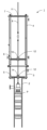
- FIG. 1 is an explanatory diagram (side view) showing a pump system according to an embodiment of the present invention.
- FIG. 2 is an explanatory diagram (perspective view) showing the pump system according to the embodiment of the present invention.
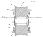
- FIG. 3 is an explanatory diagram (side view) showing a stuffing box according to an embodiment of the present invention.
- FIG. 4 is an explanatory diagram (side view) showing a stuffing box according to an embodiment of the present invention.
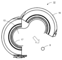
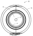
- FIG. 5 is an explanatory diagram (plan view) showing a stuffing box according to an embodiment of the present invention.
- FIG. 6 is an explanatory diagram (plan view) showing a stuffing box according to an embodiment of the present invention.
- FIG. 1 is an explanatory diagram (side view) showing a pump system according to an embodiment of the present invention.
- FIG. 2 is an explanatory diagram (perspective view) showing the pump system according to the embodiment of the present invention.
- FIG. 3 is an explanatory diagram (side view) showing a
- FIG. 7 is an explanatory diagram (side view) showing the inflow of purge gas in the embodiment of the present invention.
- FIG. 8 is an explanatory diagram (side view) showing a stuffing box according to another embodiment.
- FIG. 9 is an explanatory diagram (side view) showing a stuffing box according to another embodiment.
- FIG. 10 is an explanatory diagram (plan view) showing a stuffing box according to another embodiment.
- FIG. 11 is an explanatory diagram (plan view) showing a stuffing box according to another embodiment.
- FIG. 12 is an explanatory diagram (side view) showing a pump system according to another embodiment.
- FIG. 13 is an explanatory diagram (perspective view) showing a pump system according to another embodiment.
- the container of the present invention is a hollow container that is provided above a hollow column that is provided around a liquefied gas pump, and a cable for installing and removing the liquefied gas pump passes through the center of the container from the bottom to the top of the container.
- the container is provided with a lower plate member that is provided at the bottom of the container and has a cable through hole in the center through which the cable can pass, and a stuffing box member that is provided in the center of the lower plate member around the cable through hole and has a cable insertion hole in the center through which the cable is inserted, and the stuffing box member is provided with an opening diameter adjustment mechanism that adjusts the size of the opening diameter of the cable insertion hole.
- a stuffing box member is provided around the cable through hole, and the stuffing box member is provided with an opening diameter adjustment mechanism that adjusts the opening diameter of the cable insertion hole. Therefore, by adjusting the opening diameter of the cable insertion hole using the opening diameter adjustment mechanism of the stuffing box member, it is possible to reduce gas leaking from the cable through hole.
- the opening diameter adjustment mechanism may include a rotating ring member that can rotate around the central axis of the cable insertion hole, a pair of upper and lower linear motion ring members that are provided on the upper and lower sides of the rotating ring member, respectively, and can slide along the central axis of the cable insertion hole, and for each of the pair of upper and lower linear motion ring members, both ends of which are fixed to the linear motion ring member and the rotating ring member, and a pair of upper and lower cloth members that are provided to cover the linear motion ring member and the rotating ring member, and a pair of upper and lower cable insertion holes are formed by the pair of upper and lower cloth members, and by rotating the rotating ring member, the size of the opening diameter of the pair of upper and lower cable insertion holes can be adjusted simultaneously.
- the opening diameter adjustment mechanism is made up of the rotating ring member, a pair of upper and lower linear motion ring members, and a cloth member, and a pair of upper and lower cable insertion holes are formed by the pair of upper and lower cloth members. Then, by rotating the rotating ring member, the opening diameters of the pair of upper and lower cable insertion holes can be adjusted simultaneously.
- the rotating ring member may be provided with a gas inlet for allowing a purge gas to flow into the interior of the rotating ring member.
- purge gas can be introduced into the interior of the rotating ring member through a gas inlet provided in the rotating ring member.
- the purge gas that has flowed into the interior of the rotating ring member flows upward and downward inside the rotating ring member.
- the inflow of gas can be prevented by the purge gas flowing upward.
- the inflow of gas can be prevented by the purge gas flowing downward.
- the rotating ring member, the linear motion ring member, and the fabric member may each be splittable into two, from a closed ring state to an open ring state.
- the rotating ring member and the linear motion ring member can be split into two, so by changing the ring from an open state to a closed state inside the container, the opening diameter adjustment mechanism can be attached to the cable from the middle of the cable. Also, by changing the ring from a closed state to an open state, the opening diameter adjustment mechanism can be removed from the cable from the middle of the cable.
- the opening diameter adjustment mechanism may include an annular main body member having a cable insertion hole in the center, a pair of left and right plate-shaped sealing members that are openable and closable on the upper and lower sides of the main body member, and a spring member that biases the pair of left and right sealing members in a direction to close them toward the center, and a cable insertion hole is formed in the center of the pair of left and right sealing members, and the size of the opening diameter of the cable insertion hole may be adjusted by moving the pair of left and right sealing members in the opening direction against the elastic force of the spring member.
- the opening diameter adjustment mechanism is made up of the main body member, the seal member, and the spring member, and a cable insertion hole is formed in the center of the pair of left and right seal members. Then, by moving the pair of left and right seal members in the opening direction against the elastic force of the spring member, the opening diameter size of the pair of upper and lower cable insertion holes can be adjusted simultaneously.
- the main body member may be provided with a gas inlet for allowing a purge gas to flow into the inside of the main body member.
- purge gas can be introduced into the main body member through a gas inlet provided in the main body member.
- the purge gas that has flowed into the main body member flows upward and downward inside the main body member.
- the main body member may be split into two in the direction in which the pair of left and right seal members open.
- the main body member can be split into two, so the opening diameter adjustment mechanism can be attached to the cable from its midpoint inside the container, or the opening diameter adjustment mechanism can be removed from the cable from its midpoint.
- the container of the present invention may also include a glove box provided inside the container and configured so that a user can insert their hands from outside the container to operate the stuffing box member, and a work window disposed near the glove box and the stuffing box member so that the glove box and the stuffing box member can be viewed from outside the container.
- the user when performing maintenance on the liquefied gas pump, the user can insert their hand from outside the container into the glove box inside the container (purging container) and adjust the size of the opening diameter of the cable insertion hole using the opening diameter adjustment mechanism of the stuffing box member, thereby reducing the amount of gas leaking out from the cable penetration hole.
- the pump system of the present invention includes a liquefied gas pump and any of the containers described above.
- a stuffing box member is provided around the cable through hole, and the stuffing box member is equipped with an opening diameter adjustment mechanism that adjusts the opening diameter of the cable insertion hole. Therefore, by adjusting the opening diameter of the cable insertion hole using the opening diameter adjustment mechanism of the stuffing box member, it is possible to prevent gas from leaking from the cable through hole.
- the present invention makes it possible to prevent gas from leaking through the cable pass-through hole.
- a container according to an embodiment of the present invention will be described with reference to the drawings.
- a container used in a pump system equipped with a liquefied gas pump for delivering a cryogenic liquefied gas such as liquefied hydrogen or liquefied ammonia will be described as an example.
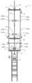
- FIGS. 1 and 2 are explanatory diagrams showing the pump system according to the embodiment.
- the pump system 1 includes a liquefied gas pump P.
- the liquefied gas pump P in one embodiment is a pump for cryogenic liquefied gas, such as a liquid hydrogen pump or a liquefied ammonia pump.
- the pump system 1 further includes a hollow column 2 provided around the liquefied gas pump P, a hollow buffer container 3 provided on the top of the column 2, and a hollow purge container 4 provided above the column 2 and on the top of the buffer container 3.
- the buffer container 3 and the purge container 4 are collectively referred to as a "container".
- This container is hollow and provided above the hollow column 2 provided around the liquefied gas pump P.
- the buffer container 3 is provided with a buffer lower plate 5 that is attached to the underside of the buffer container 3 and can be opened and closed upward.
- the purge container 4 is provided with a container lower plate 6 that is attached to the underside of the purge container 4 and can be opened and closed upward, and a container upper plate 7 that is attached to the upper side of the purge container 4 and can be opened and closed upward.
- a cable 8 for installing and removing the liquefied gas pump P passes through the center of the container from the bottom to the top.
- the buffer lower plate 5 has a cable through hole 9 in its center through which the cable 8 can pass
- the container lower plate 6 has a cable through hole 10 in its center through which the cable 8 can pass
- the container upper plate 7 has a cable through hole 11 in its center through which the cable 8 can pass.
- a stuffing box 12 is provided around the cable through hole 9 in the center of the buffer lower plate 5.
- a stuffing box 12 is also provided around the cable through hole 10 in the center of the container lower plate 6.
- a stuffing box 12 is also provided around the cable through hole 11 in the center of the container upper plate 7.
- the container 3 may be provided with a glove box 30 configured so that a user can insert his or her hand from outside the buffer container 12 to operate the stuffing box 12, and an access window 31 disposed near the glove box 30.
- the stuffing box 12 and the glove box 30 inside the buffer container 3 can be seen from outside the buffer container 3 through the access window 31.
- the purge container 4 is provided with a glove box 32 configured to allow a user to insert their hand from outside the purge container 4 to operate the stuffing box 12, and a work window 33 disposed near the glove box 32.
- the stuffing box 12 and glove box 32 of the purge container 4 are visible from outside the purge container 4 through the work window 33.
- the buffer container 4 may be provided with a second glove box 34 configured to allow a user to insert their hands from outside the container to perform manual work inside the container, and a second work window 35 located near the second glove box 34 so that the inside of the buffer container 4 can be viewed from outside the buffer container.
- the maintenance method for the liquefied gas pump according to the present invention includes a step in which a user inserts his/her hand from outside the container into a glove box 30, 32, 34 provided inside the container, and operates the opening diameter adjustment mechanism of the stuffing box 12 provided inside the container to suspend the liquefied gas pump.
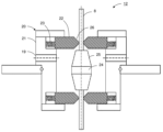
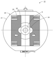
- FIGS. 3 to 7 are explanatory diagrams showing the stuffing box 12 of this embodiment.
- a cable insertion hole 13 through which the cable 8 is inserted is provided in the center of the stuffing box 12.
- the stuffing box 12 is also provided with an opening diameter adjustment mechanism 14 that adjusts the size of the opening diameter of the cable insertion hole 13.
- the opening diameter adjustment mechanism 14 includes a rotary ring 15 that can rotate around the central axis of the cable insertion hole 13, and a pair of upper and lower linear motion rings 16 that are provided above and below the rotary ring 15 and can slide along the central axis of the cable insertion hole 13. Both ends of each of the pair of upper and lower linear motion rings 16 are fixed to the linear motion ring 16 and the rotary ring 15, and a pair of upper and lower cloths 17 are provided cylindrically so as to cover the periphery of the linear motion ring 16 and the rotary ring 15.
- a pair of upper and lower cable insertion holes 13 are formed by the pair of upper and lower cloths 17.
- the material for the pair of upper and lower cloths 17 should be flexible and airtight at extremely low temperatures, and should not easily fray or chip on the surface.
- Table 1 below shows the results of tests conducted to confirm the flexibility, airtightness, and presence or absence of fraying or chipping on the surface at extremely low temperatures for four materials (materials A to D).
- material A used was the para-aramid fiber "Kevlar (registered trademark)" manufactured by Toray DuPont Co., Ltd.
- material B used “Silicone-coated heat-resistant sheet flame retardant KW-031” manufactured by Kikuchi Sheet Kogyo Co., Ltd.
- material C used "Double-sided silicone-coated synthetic heat-resistant sheet” manufactured by Kikuchi Sheet Kogyo Co., Ltd.
- test specimens of materials A to D were immersed in liquid nitrogen and cooled sufficiently, then removed from the liquid nitrogen and twisted. The test specimens were then visually inspected to see if they maintained their flexibility and if there were any defects such as chips or fraying on the surface. The airtightness of the test specimens was also checked by a simple gas test (for example, a test in which the test device is divided into two chambers for each material, one chamber is filled with a specific gas and the other chamber is filled with air, and after leaving it for a certain period of time, the increase in the gas concentration in the other chamber is measured). From the results in Table 1, it was found that it is desirable to use material B or material C as the material for the pair of upper and lower cloths 17.
- the rotating ring 15 is provided with a rotating lever 18, and the size of the opening diameter of the pair of upper and lower cable insertion holes 13 can be adjusted at the same time by inserting a hand from the glove box and operating the rotating lever 18 to rotate the rotating ring 15.
- the cloth 17 is twisted, the diameter of the cylinder is narrowed, and as a result, the cloth 17 can be tightly attached to the outer periphery of the cable 8. Therefore, the cloth 17 clings to the installation/pulling cable 8, narrowing the gas flow path and making it possible to suppress gas leakage.
- the opening diameter adjustment mechanism 14 not only adjusts the degree of constriction according to the diameter of the cable 8, but also changes the opening diameter according to the task, allowing it to be opened and closed repeatedly.
- the rotating ring 15, the linear ring 16, and the cloth 17 can each be split into two, from a closed state to an open state. This makes it possible to attach and detach the stuffing box 12 with the cable 8 passing through the container. Also, by adjusting the degree of constriction according to the diameter of the cable 8, leakage can be suppressed even for cables 8 with locally different diameters.
- the rotating ring 15 is provided with a gas inlet 19 for introducing a purge gas into the rotating ring 15.
- a purge gas for example, nitrogen gas or helium gas is used as the purge gas.
- the purge gas flows from the inside of the stuffing box 12 to the top and from the inside of the stuffing box 12 to the bottom, which has the effect of preventing the flow of gas falling from the top to the bottom of the container, and the effect of preventing the flow of gas leaking from the bottom to the top of the container. This makes it possible to prevent highly dangerous gases such as ammonia and hydrogen from leaking to the outside, and to prevent air and nitrogen from falling into the column 2.
- the rotation lever 18 depending on whether the cable 8 is not moving or is moving up and down, the space between the outer circumference of the cable 8 and the cloth 17 can be closed or opened to an appropriate interval, so that the flow rate passing through the space can be adjusted appropriately and the wasteful use and release of a large amount of purge gas can be prevented.
- a stuffing box 12 is provided around the cable through holes 9, 10, and 11, and the stuffing box 12 is provided with an opening diameter adjustment mechanism 14 that adjusts the opening diameter of the cable insertion hole 13. Therefore, by adjusting the opening diameter of the cable insertion hole 13 using the opening diameter adjustment mechanism 14 of the stuffing box 12, it is possible to reduce gas leaking from the cable through hole.
- the opening diameter adjustment mechanism 14 is made up of the rotating ring 15, a pair of upper and lower linear rings 16, and cloth 17, and the pair of upper and lower cloths 17 form a pair of upper and lower cable insertion holes 13. By rotating the rotating ring 15, the opening diameters of the pair of upper and lower cable insertion holes 13 can be adjusted simultaneously.
- purge gas can be introduced into the interior of the rotating ring 15 from the gas inlet 19 provided in the rotating ring 15.
- the purge gas that has flowed into the interior of the rotating ring 15 flows upward and downward inside the rotating ring 15.
- the purge gas flowing upward even if gas attempts to flow downward from above the linear ring 16 on the upper side of the rotating ring 15, the inflow of gas can be prevented by the purge gas flowing upward.
- the purge gas flowing downward even if gas attempts to flow upward from below the linear ring 16 on the lower side of the rotating ring 15, the inflow of gas can be prevented by the purge gas flowing downward.
- the rotating ring 15, the linear motion ring 16, and the fabric 17 can be split into two, so that by changing the rings from an open state to a closed state inside the container, the opening diameter adjustment mechanism 14 can be attached to the cable 8 at the midpoint of the cable 8. Also, by changing the rings from a closed state to an open state, the opening diameter adjustment mechanism 14 can be removed from the cable 8 at the midpoint of the cable 8.
- the containers (buffer container 3, purge container 4) of this embodiment may also be provided with a glove box 30 that is provided inside the container and configured so that a user can insert their hands from outside the container to operate the stuffing box 12, and a work window 31 that is located near the glove box 30 and the stuffing box 12 so that the glove box 30 and the stuffing box 12 can be viewed from outside the container.
- the user when performing maintenance on the liquefied gas pump, the user can insert their hand from outside the container into the glove box 30 inside the container (purge container 3) and adjust the size of the opening diameter of the cable insertion hole 13 using the opening diameter adjustment mechanism 14 of the stuffing box 12, thereby reducing the amount of gas leaking out from the cable penetration hole.
- the opening diameter adjustment mechanism 20 may include an annular main body 21 having a cable insertion hole 13 in the center, and a pair of left and right plate-shaped seal members 22 that are provided on the upper and lower sides of the main body 21 in an openable and closable manner.
- the cable insertion hole 13 is formed in the center of the pair of left and right seal members 22, and the pair of left and right seal members 22 are biased in a direction to close toward the center by the elastic force of a pressing spring 23. Then, the pair of left and right seal members 22 move in the opening direction against the elastic force of the pressing spring 23, whereby the size of the opening diameter of the cable insertion hole 13 can be adjusted.
- the opening diameter of the cable insertion hole 13 can be changed simply by lifting and lowering the cable 8, improving workability.
- the main body 21 of the opening diameter adjustment mechanism 20 is provided with a gas inlet 19 for allowing purging gas to flow into the main body 21.
- the main body 21 of the opening diameter adjustment mechanism 20 can be split into two in the direction in which the pair of left and right sealing materials 22 open.
- the opening diameter adjustment mechanism 20 is also made up of the main body 21, the seal material 22, and the pressing spring 23, and the cable insertion hole 13 is formed in the center of the pair of left and right seal materials 22. Then, by moving the pair of left and right seal materials 22 in the opening direction against the elastic force of the pressing spring 23, the opening diameter of the pair of upper and lower cable insertion holes 13 can be adjusted simultaneously.
- purge gas can be introduced into the main body 21 through the gas inlet 19 provided in the main body 21.
- the purge gas that has flowed into the main body 21 flows upward and downward inside the main body 21.
- the inflow of gas can be prevented by the purge gas flowing toward the upper side.
- the inflow of gas can be prevented by the purge gas flowing toward the lower side.
- the main body 21 of the opening diameter adjustment mechanism 20 can be split into two, so the opening diameter adjustment mechanism 20 can be attached to the cable 8 at the middle of the cable 8 inside the container, or the opening diameter adjustment mechanism 20 can be detached from the cable 8 at the middle of the cable 8.
- the container of the present invention has the effect of preventing gas leakage from the cable penetration hole, and is useful as a pump system equipped with a liquefied gas pump that delivers extremely low temperature liquefied gas such as liquefied hydrogen or liquefied ammonia.
Landscapes
- Engineering & Computer Science (AREA)
- Mechanical Engineering (AREA)
- General Engineering & Computer Science (AREA)
- Filling Or Discharging Of Gas Storage Vessels (AREA)
Abstract
Description
コンテナは、
コンテナの下部に設けられ、中央部にケーブルが貫通可能なケーブル貫通孔を有するロアープレート部材と、
ロアープレート部材の中央部においてケーブル貫通孔の周囲に設けられ、中央部にケーブルが挿通されるケーブル挿通孔を有するスタフィングボックス部材と、
を備え、
スタフィングボックス部材は、ケーブル挿通孔の開口径の大きさを調整する開口径調整機構を備える。
以下、本発明の実施の形態のコンテナについて、図面を用いて説明する。本実施の形態では、液化水素や液化アンモニアなどの極低温の液化ガスを送出する液化ガスポンプを備えるポンプシステム等に用いられるコンテナの場合を例示する。

例えば、図8~図11には、開口径調整機構20の他の例が示される。図8~図11に示すように、開口径調整機構20は、中央部にケーブル挿通孔13を有する環状の本体21と、本体21の上側と下側において、それぞれ開閉可能に設けられる左右一対の板状のシール材22を備えてもよい。この場合、左右一対のシール材22の中央部に、ケーブル挿通孔13が形成されており、左右一対のシール材22は、押し付けバネ23の弾性力によって、それぞれ中央部に向けて閉じる方向に付勢されている。そして、押し付けバネ23の弾性力に抗して左右一対のシール材22が開く方向に移動することにより、ケーブル挿通孔13の開口径の大きさが調整可能とされている。
2 コラム
3 バッファコンテナ(コンテナ)
4 パージコンテナ(コンテナ)
5 バッファーロアープレート(ロアープレート部材)
6 コンテナロアープレート(ロアープレート部材)
7 コンテナアッパープレート
8 ケーブル
9 ケーブル貫通孔
10 ケーブル貫通孔
11 ケーブル貫通孔
12 スタフィングボックス(スタフィングボックス部材)
13 ケーブル挿通孔
14 開口径調整機構
15 回転環
16 直動環
17 布
18 回転用レバー
19 ガス流入口
20 開口径調整機構
21 本体
22 シール材
23 押し付けバネ
24 リンク
25 テーパ部
26 テーパ部
30 グローブボックス
31 作業窓
32 グローブボックス
33 作業窓
34 グローブボックス
35 作業窓
P 液化ガスポンプ
Claims (9)
- 液化ガスポンプの周囲に設けられた中空のコラムの上方に設けられる中空のコンテナであって、前記コンテナの中央部には、前記コンテナの下方から上方に向けて前記液化ガスポンプの据付・引抜用のケーブルが貫通されており、
前記コンテナは、
前記コンテナの下部に設けられ、中央部に前記ケーブルが貫通可能なケーブル貫通孔を有するロアープレート部材と、
前記ロアープレート部材の中央部において前記ケーブル貫通孔の周囲に設けられ、中央部に前記ケーブルが挿通されるケーブル挿通孔を有するスタフィングボックス部材と、
を備え、
前記スタフィングボックス部材は、前記ケーブル挿通孔の開口径の大きさを調整する開口径調整機構を備える、コンテナ。 - 前記開口径調整機構は、
前記ケーブル挿通孔の中心軸を中心として回転可能な回転環部材と、
前記回転環部材の上側と下側にそれぞれ設けられ、前記ケーブル挿通孔の中心軸に沿ってスライド可能な上下一対の直動環部材と、
前記上下一対の直動環部材の各々について、前記直動環部材と前記回転環部材とに両端が固定され、前記直動環部材と前記回転環部材の周囲を覆うように設けられる上下一対の布部材と、
を備え、
前記上下一対の布部材によって、上下一対の前記ケーブル挿通孔が形成され、
前記回転環部材を回転させることにより、前記上下一対のケーブル挿通孔の開口径の大きさが同時に調整可能である、請求項1に記載のコンテナ。 - 前記回転環部材には、前記回転環部材の内部にパージ用ガスを流入させるためのガス流入口が設けられている、請求項2に記載のコンテナ。
- 前記回転環部材と前記直動環部材と前記布部材は、それぞれ、環が閉じた状態から環が開いた状態へと二つ割り可能とされている、請求項2または請求項3に記載のコンテナ。
- 前記開口径調整機構は、
中央部に前記ケーブル挿通孔を有する環状の本体部材と、
前記本体部材の上側と下側において、それぞれ開閉可能に設けられる左右一対の板状のシール部材と、
前記左右一対のシール部材をそれぞれ中央部に向けて閉じる方向に付勢するバネ部材と、
を備え、
前記左右一対のシール部材の中央部には、前記ケーブル挿通孔が形成され、
前記バネ部材の弾性力に抗して前記左右一対のシール部材が開く方向に移動することにより、前記ケーブル挿通孔の開口径の大きさが調整可能である、請求項1に記載のコンテナ。 - 前記本体部材には、前記本体部材の内部にパージ用ガスを流入させるためのガス流入口が設けられている、請求項5に記載のコンテナ。
- 前記本体部材は、前記左右一対のシール部材が開く方向に二つ割り可能とされている、請求項5または請求項6に記載のコンテナ。
- 前記コンテナの内部に設けられ、前記スタフィングボックス部材を操作するために前記コンテナの外部からユーザが手を挿入できるように構成されているグローブボックスと、
前記グローブボックスおよび前記前記スタフィングボックス部材を前記コンテナの外部から視認できるように、前記グローブボックスおよび前記スタフィングボックス部材の近傍に配置される作業窓と、
を備える、請求項1に記載のコンテナ。 - 液化ガスポンプと、
請求項1~請求項8のいずれかに記載のコンテナと、
を備える、ポンプシステム。
Priority Applications (3)
| Application Number | Priority Date | Filing Date | Title |
|---|---|---|---|
| AU2024289066A AU2024289066A1 (en) | 2023-07-06 | 2024-06-04 | Container and pump system |
| KR1020267003505A KR20260030915A (ko) | 2023-07-06 | 2024-06-04 | 컨테이너 및 펌프 시스템 |
| CN202480045132.8A CN121443882A (zh) | 2023-07-06 | 2024-06-04 | 容器及泵系统 |
Applications Claiming Priority (2)
| Application Number | Priority Date | Filing Date | Title |
|---|---|---|---|
| JP2023111354A JP2025008818A (ja) | 2023-07-06 | 2023-07-06 | コンテナおよびポンプシステム |
| JP2023-111354 | 2023-07-06 |
Publications (1)
| Publication Number | Publication Date |
|---|---|
| WO2025009301A1 true WO2025009301A1 (ja) | 2025-01-09 |
Family
ID=94171997
Family Applications (1)
| Application Number | Title | Priority Date | Filing Date |
|---|---|---|---|
| PCT/JP2024/020278 Ceased WO2025009301A1 (ja) | 2023-07-06 | 2024-06-04 | コンテナおよびポンプシステム |
Country Status (5)
| Country | Link |
|---|---|
| JP (1) | JP2025008818A (ja) |
| KR (1) | KR20260030915A (ja) |
| CN (1) | CN121443882A (ja) |
| AU (1) | AU2024289066A1 (ja) |
| WO (1) | WO2025009301A1 (ja) |
Citations (7)
| Publication number | Priority date | Publication date | Assignee | Title |
|---|---|---|---|---|
| JPS5958194A (ja) * | 1982-09-27 | 1984-04-03 | Shinko Kinzoku Kogyosho:Kk | 液化ガスタンク用ポンプ装置 |
| JPH09324792A (ja) * | 1996-06-03 | 1997-12-16 | Kubota Corp | 軸封部構造 |
| JP2003200148A (ja) * | 2001-12-28 | 2003-07-15 | Toshiba Corp | 有害有機物収容機器解体装置および同解体方法 |
| JP2011011274A (ja) * | 2009-06-30 | 2011-01-20 | Mitsui Eng & Shipbuild Co Ltd | 移動式グローブボックス |
| JP2018025130A (ja) * | 2016-08-09 | 2018-02-15 | 株式会社荏原製作所 | ポンプのための軸封装置及び軸封装置を備えるポンプ |
| JP2018080801A (ja) | 2016-11-18 | 2018-05-24 | 川崎重工業株式会社 | 低温液化ガスポンプ用断熱容器 |
| WO2023136246A1 (ja) * | 2022-01-11 | 2023-07-20 | 株式会社荏原製作所 | コンテナおよびポンプシステム |
-
2023
- 2023-07-06 JP JP2023111354A patent/JP2025008818A/ja active Pending
-
2024
- 2024-06-04 CN CN202480045132.8A patent/CN121443882A/zh active Pending
- 2024-06-04 KR KR1020267003505A patent/KR20260030915A/ko active Pending
- 2024-06-04 WO PCT/JP2024/020278 patent/WO2025009301A1/ja not_active Ceased
- 2024-06-04 AU AU2024289066A patent/AU2024289066A1/en active Pending
Patent Citations (7)
| Publication number | Priority date | Publication date | Assignee | Title |
|---|---|---|---|---|
| JPS5958194A (ja) * | 1982-09-27 | 1984-04-03 | Shinko Kinzoku Kogyosho:Kk | 液化ガスタンク用ポンプ装置 |
| JPH09324792A (ja) * | 1996-06-03 | 1997-12-16 | Kubota Corp | 軸封部構造 |
| JP2003200148A (ja) * | 2001-12-28 | 2003-07-15 | Toshiba Corp | 有害有機物収容機器解体装置および同解体方法 |
| JP2011011274A (ja) * | 2009-06-30 | 2011-01-20 | Mitsui Eng & Shipbuild Co Ltd | 移動式グローブボックス |
| JP2018025130A (ja) * | 2016-08-09 | 2018-02-15 | 株式会社荏原製作所 | ポンプのための軸封装置及び軸封装置を備えるポンプ |
| JP2018080801A (ja) | 2016-11-18 | 2018-05-24 | 川崎重工業株式会社 | 低温液化ガスポンプ用断熱容器 |
| WO2023136246A1 (ja) * | 2022-01-11 | 2023-07-20 | 株式会社荏原製作所 | コンテナおよびポンプシステム |
Also Published As
| Publication number | Publication date |
|---|---|
| JP2025008818A (ja) | 2025-01-20 |
| KR20260030915A (ko) | 2026-03-06 |
| AU2024289066A1 (en) | 2026-01-15 |
| CN121443882A (zh) | 2026-01-30 |
Similar Documents
| Publication | Publication Date | Title |
|---|---|---|
| WO2023136246A1 (ja) | コンテナおよびポンプシステム | |
| US7780248B2 (en) | Glovebox for a double wall containment module | |
| WO2025009301A1 (ja) | コンテナおよびポンプシステム | |
| BR0114452A (pt) | Sistema de teste de poço, método para realizar um teste de poço, e, válvula de controle de fluxo | |
| WO2002074504A2 (en) | Method and housing for performing operations on a material | |
| US3337279A (en) | Gas purged dry box glove | |
| US20080278041A1 (en) | Cable port for biosafety cabinet | |
| JP2016003980A (ja) | 試験装置及び恒温装置 | |
| BR0300832A (pt) | Gabinete de refrigerador isolado à vácuo, e, método para evacuar um recipiente substancialmente estanque a gás | |
| WO2004050572A1 (en) | Method and apparatus for making optical fibres | |
| Olson et al. | Evaluating material flammability in microgravity and martian gravity compared to the nasa standard normal gravity test | |
| JP5412188B2 (ja) | パスボックス及びアイソレーター装置 | |
| JP2006517658A (ja) | リークを認知するための方法および装置 | |
| CN119000995A (zh) | 编织型防火套管耐火检测装置 | |
| WO2023120591A1 (ja) | コンテナ、ポンプシステム、メンテナンス方法 | |
| CN109141972A (zh) | 水质采样器 | |
| KR101961906B1 (ko) | 글로브 밸브 | |
| KR101973119B1 (ko) | 체크 밸브 | |
| KR102333627B1 (ko) | 공기흐름조절기 | |
| CN223295775U (zh) | 一种适用于不同规格圆环链试样的拉拉疲劳夹具 | |
| KR101743582B1 (ko) | 해양 구조물용 방화 댐퍼의 구동 장치 | |
| KR20220096813A (ko) | 볼밸브 스템 지그 | |
| KR102380073B1 (ko) | 압력용기 파열 시험 잔류물 수거용 청소망을 구비한 안전 챔버장치 | |
| US3469437A (en) | Horizontal cryostat for fatigue testing | |
| US869066A (en) | Apparatus for testing miner's safety-lamps. |
Legal Events
| Date | Code | Title | Description |
|---|---|---|---|
| 121 | Ep: the epo has been informed by wipo that ep was designated in this application |
Ref document number: 24835821 Country of ref document: EP Kind code of ref document: A1 |
|
| WWE | Wipo information: entry into national phase |
Ref document number: AU2024289066 Country of ref document: AU |
|
| ENP | Entry into the national phase |
Ref document number: 2024289066 Country of ref document: AU Date of ref document: 20240604 Kind code of ref document: A |
|
| ENP | Entry into the national phase |
Ref document number: 1020267003505 Country of ref document: KR Free format text: ST27 STATUS EVENT CODE: A-0-1-A10-A15-NAP-PA0105 (AS PROVIDED BY THE NATIONAL OFFICE) |
|
| WWE | Wipo information: entry into national phase |
Ref document number: 2024835821 Country of ref document: EP Ref document number: 1020267003505 Country of ref document: KR |
|
| NENP | Non-entry into the national phase |
Ref country code: DE |
|
| ENP | Entry into the national phase |
Ref document number: 2024835821 Country of ref document: EP Effective date: 20260203 |
|
| WWP | Wipo information: published in national office |
Ref document number: 1020267003505 Country of ref document: KR |