WO2025009255A1 - 電波センサ、検知方法、及び検知プログラム - Google Patents
電波センサ、検知方法、及び検知プログラム Download PDFInfo
- Publication number
- WO2025009255A1 WO2025009255A1 PCT/JP2024/016343 JP2024016343W WO2025009255A1 WO 2025009255 A1 WO2025009255 A1 WO 2025009255A1 JP 2024016343 W JP2024016343 W JP 2024016343W WO 2025009255 A1 WO2025009255 A1 WO 2025009255A1
- Authority
- WO
- WIPO (PCT)
- Prior art keywords
- radio wave
- roadway
- wave sensor
- vehicle
- crosswalk
- Prior art date
- Legal status (The legal status is an assumption and is not a legal conclusion. Google has not performed a legal analysis and makes no representation as to the accuracy of the status listed.)
- Ceased
Links
Images




Classifications
-
- G—PHYSICS
- G01—MEASURING; TESTING
- G01S—RADIO DIRECTION-FINDING; RADIO NAVIGATION; DETERMINING DISTANCE OR VELOCITY BY USE OF RADIO WAVES; LOCATING OR PRESENCE-DETECTING BY USE OF THE REFLECTION OR RERADIATION OF RADIO WAVES; ANALOGOUS ARRANGEMENTS USING OTHER WAVES
- G01S13/00—Systems using the reflection or reradiation of radio waves, e.g. radar systems; Analogous systems using reflection or reradiation of waves whose nature or wavelength is irrelevant or unspecified
- G01S13/02—Systems using reflection of radio waves, e.g. primary radar systems; Analogous systems
- G01S13/50—Systems of measurement based on relative movement of target
- G01S13/58—Velocity or trajectory determination systems; Sense-of-movement determination systems
-
- G—PHYSICS
- G01—MEASURING; TESTING
- G01S—RADIO DIRECTION-FINDING; RADIO NAVIGATION; DETERMINING DISTANCE OR VELOCITY BY USE OF RADIO WAVES; LOCATING OR PRESENCE-DETECTING BY USE OF THE REFLECTION OR RERADIATION OF RADIO WAVES; ANALOGOUS ARRANGEMENTS USING OTHER WAVES
- G01S13/00—Systems using the reflection or reradiation of radio waves, e.g. radar systems; Analogous systems using reflection or reradiation of waves whose nature or wavelength is irrelevant or unspecified
- G01S13/88—Radar or analogous systems specially adapted for specific applications
- G01S13/91—Radar or analogous systems specially adapted for specific applications for traffic control
-
- G—PHYSICS
- G08—SIGNALLING
- G08G—TRAFFIC CONTROL SYSTEMS
- G08G1/00—Traffic control systems for road vehicles
- G08G1/01—Detecting movement of traffic to be counted or controlled
Definitions
- This disclosure relates to a radio wave sensor, a detection method, and a detection program.
- This application claims priority to Japanese Application No. 2023-109960, filed on July 4, 2023, and incorporates by reference all of the contents of said Japanese application.
- Patent Document 1 discloses a radar device that suppresses false positives and extracts only targets by performing cluster analysis based on the difference in density distribution between targets and false positives on a three-dimensional coordinate axis.
- a radio wave sensor is a radio wave sensor that detects objects in a radio wave irradiation area including a crosswalk by irradiating the area with radio waves, and includes a transmitting antenna that irradiates radio waves to the radio wave irradiation area, a receiving antenna that receives the radio waves irradiated from the transmitting antenna and reflected by the object, a measuring unit that measures the line-of-sight velocity of the object, which is the speed in a straight line connecting the radio wave sensor and the object, based on the radio waves irradiated from the transmitting antenna and the reflected waves received by the receiving antenna, and a vehicle detection unit that detects vehicles traveling on the roadway crossing the crosswalk by identifying objects for which the line-of-sight velocity measured by the measuring unit is zero.
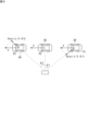
- FIG. 1 is a diagram illustrating an example of use of an infrastructure radio wave sensor according to an embodiment.
- FIG. 2 is a perspective view illustrating an example of an external configuration of the infrastructure radio wave sensor according to the embodiment.
- FIG. 3 is a block diagram illustrating an example of a hardware configuration of the infrastructure radio wave sensor according to the embodiment.
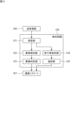
- FIG. 4 is a functional block diagram illustrating an example of functions of the infrastructure radio wave sensor according to the embodiment.
- FIG. 5A is a diagram illustrating a first example of installation of an infrastructure radio wave sensor according to an embodiment.
- FIG. 5B is a diagram illustrating a second example of installation of the infrastructure radio wave sensor according to the embodiment.
- FIG. 5C is a diagram illustrating a third example of installation of the infrastructure radio wave sensor according to the embodiment.
- FIG. 5A is a diagram illustrating a first example of installation of an infrastructure radio wave sensor according to an embodiment.
- FIG. 5B is a diagram illustrating a second example of installation of the infrastructure radio wave sensor according to the
- FIG. 6 is a diagram for explaining vehicle detection by the infrastructure radio wave sensor according to the embodiment.
- FIG. 7 is a diagram showing an example of the distance between the infrastructure radio wave sensor and the lane.
- FIG. 8 is a graph for explaining the principle of determining a lane.
- FIG. 9 is a diagram illustrating an example of a restricted installation range of an infrastructure radio wave sensor according to the embodiment.
- FIG. 10 is a flowchart illustrating an example of the operation of the infrastructure radio wave sensor according to the embodiment.
- a radio wave sensor can detect the speed of an object in a straight line connecting the object and the radio wave sensor (hereinafter, also referred to as "line-of-sight speed").
- line-of-sight speed the speed of an object in a straight line connecting the object and the radio wave sensor
- the maximum detectable speed which is the upper limit of the detectable speed
- the speed resolution decreases and it becomes impossible to accurately detect the speed of a slow-moving pedestrian.
- the speed resolution is increased to accurately detect the speed of a pedestrian, the maximum detectable speed decreases and it becomes impossible to accurately detect the speed of the vehicle.
- ⁇ Effects of the present disclosure> According to the present disclosure, a plurality of types of objects having large differences in speed can be detected by the radio wave sensor.
- the radio wave sensor is a radio wave sensor that detects an object in a radio wave irradiation area including at least a part of a crosswalk by irradiating the radio wave to the radio wave irradiation area, and includes a transmitting antenna that irradiates radio waves to the radio wave irradiation area, a receiving antenna that receives the radio waves irradiated from the transmitting antenna by the object, a measuring unit that measures the line-of-sight velocity of the object, which is the speed in a straight line connecting the radio wave sensor and the object, based on the radio waves irradiated from the transmitting antenna and the reflected waves received by the receiving antenna, and a vehicle detection unit that detects a vehicle traveling on a roadway crossing the crosswalk by identifying an object for which the line-of-sight velocity measured by the measuring unit is zero.
- a transmitting/receiving surface may be further provided, which is disposed in front of the transmitting antenna and the receiving antenna, and which irradiates the radio waves to the radio wave irradiation area and receives the reflected waves, and the projection central axis obtained by projecting the normal line of the transmitting/receiving surface from the center of the transmitting/receiving surface in the vertical direction onto the ground surface may intersect with the crosswalk. This allows a large part of the crosswalk to be included in the radio wave irradiation area.
- the lane direction of the roadway crossing the crosswalk may be perpendicular to one of the irradiation directions of the radio waves irradiated from the transmitting/receiving surface. This makes the line-of-sight speed of the vehicle zero at a point on the roadway where the lane direction and one of the irradiation directions of the radio waves intersect perpendicularly, thereby suppressing the line-of-sight speed of the vehicle.
- the line-of-sight velocity of the vehicle at the point where the projection central axis intersects with the roadway may be 50% or less of the vehicle's traveling speed. This makes it possible to suppress the line-of-sight velocity of the vehicle.
- the vehicle detection unit may detect the vehicle traveling on the roadway by identifying an object whose radial velocity measured by the measurement unit transitions from positive to negative or from negative to positive. This allows accurate detection of vehicles traveling on the roadway.
- the measurement unit may measure the distance from the radio wave sensor to the object based on the radio waves irradiated from the transmitting antenna and the reflected waves received by the receiving antenna, and the radio wave sensor may further include a lane determination unit that determines the lane in which the vehicle is traveling based on the distance of the object at a zero crossing point where the line-of-sight velocity transitions from positive to negative or from negative to positive.
- the distance between the radio wave sensor and the zero crossing point differs for each lane. Therefore, the lane in which the vehicle is traveling can be determined by using the distance measurement results.
- the second roadway that intersects with the first roadway that crosses the crosswalk may not be included in the radio wave irradiation area. This makes it possible to prevent a vehicle traveling on the second roadway from being mistakenly detected as a vehicle traveling on the first roadway.
- the radio wave sensor does not have to be installed at an intersection between a first roadway, which is the roadway that crosses the crosswalk, and a second roadway different from the first roadway, within a range of 10% of the radius of curvature of the center line of the lane from the center of curvature of the arc-shaped lane connecting the first roadway to the second roadway or from the second roadway to the first roadway. If the radio wave sensor is installed within the above range, the line-of-sight speed of vehicles entering from the first roadway to the second roadway or from the second roadway to the first roadway (i.e., turning right or left at the intersection) will be close to zero, and these vehicles will not be able to be detected by the radio wave sensor. Therefore, by installing the radio wave sensor outside the above range, vehicles turning right or left at the intersection can be detected by the radio wave sensor.
- the detection method is a detection method using a radio wave sensor that detects an object in a radio wave irradiation area including a crosswalk by irradiating the area with radio waves, and includes the steps of irradiating radio waves from a transmitting antenna to the radio wave irradiation area, receiving the radio waves irradiated from the transmitting antenna by the object with a receiving antenna, measuring the line-of-sight velocity of the object, which is the speed in a straight line connecting the radio wave sensor and the object, based on the radio waves irradiated from the transmitting antenna and the reflected waves received by the receiving antenna, and detecting a vehicle traveling on a roadway crossing the crosswalk by identifying an object for which the measured line-of-sight velocity is zero.
- the detection program according to this embodiment is a detection program used in a radio wave sensor that detects an object in a radio wave irradiation area including a crosswalk by irradiating the area with radio waves.
- the detection program causes a computer to execute the steps of acquiring the line-of-sight velocity of the object, which is the speed in a straight line connecting the radio wave sensor and the object, measured based on the radio waves irradiated from the transmitting antenna to the radio wave irradiation area and the reflected waves of the radio waves received by the receiving antenna by the object, and detecting a vehicle traveling on a roadway crossing the crosswalk by identifying an object for which the acquired line-of-sight velocity is zero.
- This makes it possible to make the line-of-sight velocity of a vehicle traveling on a roadway crossing a crosswalk lower than the traveling speed. Therefore, the maximum detection speed can be set low, and pedestrians and vehicles on the crosswalk can be detected by the radio wave sensor.
- the present disclosure can be realized not only as a radio wave sensor having the above-mentioned characteristic configuration, a detection method for a radio wave sensor having steps each consisting of characteristic processing, and a detection program for causing a radio wave sensor to execute the characteristic processing, but also as a part of the radio wave sensor realized as a semiconductor integrated circuit, or as a system including a radio wave sensor.
- Infrastructure radio wave sensor] 1 is a diagram showing an example of use of an infrastructure radio wave sensor according to an embodiment.
- the infrastructure radio wave sensor 10 according to this embodiment is a radio wave radar for traffic monitoring, and detects objects (pedestrians, bicycles (including passengers), and vehicles) on a crosswalk 20.
- the infrastructure radio wave sensor 10 is, for example, a millimeter wave radar.
- the infrastructure radio wave sensor 10 is attached to a structure 50 installed on a road.
- the structure 50 is several meters tall, and the infrastructure radio wave sensor 10 is installed several meters above the ground.
- the structure 50 includes, for example, a pole 51 and an arm 52 installed near the top end of the pole 51, and the infrastructure radio wave sensor 10 is attached to the arm 52.
- General radio wave sensors for traffic monitoring are installed so that the front of the sensor faces a point on the roadway directly above the roadway in the lane direction (vehicle travel direction) in order to detect vehicles traveling on the roadway.
- the infrastructure radio wave sensor 10 of this embodiment irradiates radio waves (millimeter waves) onto the crosswalk 20 and receives the reflected waves to detect objects (e.g., pedestrians, bicycles) on the crosswalk 20 and vehicles traveling on the roadway 60 crossing the crosswalk 20.
- the infrastructure radio wave sensor 10 can detect the distance from the infrastructure radio wave sensor 10 to the object, the speed of the object (the speed in the straight line connecting the infrastructure radio wave sensor 10 and the object; hereinafter also referred to as "line-of-sight speed"), and the horizontal angle (azimuth angle) of the position of the object relative to the front direction of the infrastructure radio wave sensor 10.
- a detection area 30 is set, which is a range on the road for detecting objects.
- the detection area 30 is set as a part of the radio wave irradiation area 40 of the infrastructure radio wave sensor 10.
- the radio wave irradiation area 40 covers the detection area 30.
- a detection area 30 that includes the entire crosswalk 20.
- the radio wave irradiation area 40 is a range in which an object reflects the radio waves irradiated by the infrastructure radio wave sensor 10 and the infrastructure radio wave sensor 10 can detect the object by the reflected waves from the object, and does not include a range in which the infrastructure radio wave sensor 10 cannot detect an object even if it can irradiate radio waves.
- the radio wave irradiation area 40 is not limited to this, and may be the entire range in which the infrastructure radio wave sensor 10 can irradiate radio waves.
- the infrastructure radio wave sensor 10 used to measure the number of pedestrians and bicycles (including passengers; hereinafter, pedestrians and bicycles are simply referred to as "pedestrians") crossing the crosswalk 20 or to control traffic signals installed on the crosswalk 20 is required to detect not only pedestrians on the crosswalk, but also pedestrians waiting to cross on the sidewalk adjacent to the crosswalk 20.
- the detection area 30 includes not only the area of the crosswalk 20, but also an area on the sidewalk where pedestrians wait to cross.
- the detection area 30 is an area that extends from the crosswalk 20 on both sides in the longitudinal direction of the crosswalk 20 (the direction in which pedestrians pass on the crosswalk).
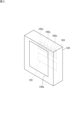
- FIG. 2 is a perspective view showing an example of the external configuration of the infrastructure radio wave sensor 10 according to the embodiment.
- the infrastructure radio wave sensor 10 includes a housing 140 having a transmission/reception surface 140a on one side for transmitting and receiving radio waves.
- the housing 140 accommodates a transmission/reception unit 104 and a detection circuit 120.
- the transmission/reception unit 104 includes a transmission antenna 105a and a plurality of (for example, four) reception antennas 106a.
- the infrastructure radio wave sensor 10 transmits a modulated wave, which is a radio wave, from the transmission antenna 105a through the transmission/reception surface 140a.
- the modulated wave hits an object and is reflected, and the reception antenna 106a receives the reflected wave.
- the transmission/reception unit 104 and the detection circuit 120 perform signal processing on the transmission wave signal and the reception wave signal to detect the distance to the object, the line-of-sight velocity of the object, and the azimuth angle at which the object is present.
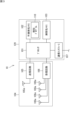
- FIG. 3 is a block diagram showing an example of the hardware configuration of an infrastructure radio wave sensor according to an embodiment.
- the infrastructure radio wave sensor 10 includes a transmission/reception unit 104 and a detection circuit 120.
- the detection circuit 120 includes a processor 101, a non-volatile memory 102, a volatile memory 103, and a communication interface 107.
- the transceiver unit 104 includes a transmission circuit 105 and a reception circuit 106.
- the transmission circuit 105 includes a transmission antenna 105a. Note that the number of transmission antennas 105a is not limited to one, and may be multiple.
- the transmission circuit 105 generates a modulated wave and transmits the generated modulated wave from the transmission antenna 105a.
- the receiving circuit 106 includes a receiving antenna 106a. In order to detect the azimuth angle of an object, multiple receiving antennas 106a (four in the figure) are provided. The receiving circuit 106 performs signal processing on the received reflected wave. The reflected wave data generated by the signal processing is provided to the processor 101. The processor 101 analyzes the reflected wave data and detects the position (distance and azimuth angle) and radial velocity of the object.
- the volatile memory 103 is, for example, a semiconductor memory such as SRAM (Static Random Access Memory) or DRAM (Dynamic Random Access Memory).
- the non-volatile memory 102 is, for example, a flash memory, a hard disk, or a ROM (Read Only Memory).
- the non-volatile memory 102 stores a detection program 110, which is a computer program, and data used to execute the detection program 110. Each function of the infrastructure radio wave sensor 10 is exercised by the processor 101 executing the detection program 110.
- the detection program 110 can be stored in a recording medium such as a flash memory, a ROM, or a CD-ROM.
- the processor 101 can detect the position (distance and azimuth) and line of sight velocity of an object by the detection program 110.
- the processor 101 is, for example, a CPU (Central Processing Unit). However, the processor 101 is not limited to a CPU.
- the processor 101 may be a GPU (Graphics Processing Unit).
- the processor 101 may be, for example, an ASIC (Application Specific Integrated Circuit) or a programmable logic device such as an FPGA (Field Programmable Gate Array). In this case, the ASIC or programmable logic device is configured to be capable of executing the same processing as the detection program 110.
- ASIC Application Specific Integrated Circuit
- FPGA Field Programmable Gate Array
- the communication interface 107 can communicate with external devices.
- the communication interface 107 is a wireless communication interface, and can transmit detection result data (hereinafter also referred to as "detection data") to a server operated by a road traffic information center or the like, a control device for controlling traffic signals installed at an intersection including the crosswalk 20, or a vehicle (mounted on an on-board device) in the vicinity of the infrastructure radio wave sensor 10.
- [3. Functions of infrastructure radio wave sensors] 4 is a functional block diagram showing an example of functions of the infrastructure radio wave sensor according to the embodiment.
- the infrastructure radio wave sensor 10 functions as a measurement unit 121, a vehicle detection unit 122, a lane determination unit 123, a pedestrian detection unit 124, and a tracking unit 125.
- the measurement unit 121 measures the radial velocity of an object based on the radio waves emitted from the transmitting antenna 105a and the reflected waves received by the receiving antenna 106a.
- the measurement unit 121 measures the distance from the infrastructure radio wave sensor 10 to the object based on the radio waves emitted from the transmitting antenna 105a and the reflected waves received by the receiving antenna 106a. Furthermore, the measurement unit 121 measures the angle (azimuth angle) of the object with respect to a straight line (hereinafter also referred to as the "projection center axis") obtained by projecting the normal of the transmitting/receiving surface 104a vertically from the center of the transmitting/receiving surface 104a onto the ground surface based on the radio waves emitted from the transmitting antenna 105a and the reflected waves received by the receiving antenna 106a.
- a straight line hereinafter also referred to as the "projection center axis”
- the measurement unit 121 generates reflected wave data that indicates information including the signal level of the reflected wave for each position where the radio wave is irradiated.
- the transmission circuit 105 transmits a transmission signal, which is a modulated wave, from the transmission antenna 105a.
- the transmission signal from the transmission antenna 105a hits an object and is reflected.
- the receiving antenna 106a receives the reflected wave from the object.
- the measurement unit 121 combines the modulated wave signal output from the transmission circuit 105 and the reflected wave signal output from the receiving circuit 106 to generate an intermediate frequency signal (hereinafter referred to as an "IF signal").
- the measurement unit 121 performs a fast Fourier transform (FFT) on the IF signal to obtain information on distance, radial velocity, and azimuth angle.
- FFT fast Fourier transform
- a transmission signal (chirp) is sent from transmitting antenna 105a at regular intervals.
- a moving object reflects the transmission signal at two different points, and receiving antenna 106a receives each reflected wave.
- Measurement unit 121 measures the radial velocity of the object from the phase difference between multiple IF signals obtained from the moving object.
- the line-of-sight velocity measured by the measurement unit 121 is output from the measurement unit 121 to the vehicle detection unit 122.
- the vehicle detection unit 122 detects vehicles traveling on the roadway 60 crossing the crosswalk 20 by identifying objects for which the line-of-sight velocity measured by the measurement unit 121 is zero.
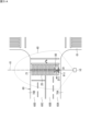
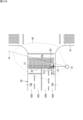
- FIG. 5A is a diagram showing a first example of the installation of an infrastructure radio wave sensor according to an embodiment.
- Pedestrian walkways 70A and 70B are provided on both sides of the roadway 60 that crosses the crosswalk 20.
- the infrastructure radio wave sensor 10 is installed on the sidewalk 70A at a position and angle where the projection center axis 41 intersects with the crosswalk 20. Note that "the projection center axis 41 intersects with the crosswalk 20" here means that the projection center axis 41 overlaps with the crosswalk 20.
- the projection center axis 41 is parallel to the longitudinal direction of the crosswalk 20, and the infrastructure radio wave sensor 10 is installed at a position and angle that passes through the approximate center of the width of the crosswalk 20.
- the radio wave irradiation area 40 includes the entire crosswalk 20.
- lanes 60A, 60B, 60C, and 60D are provided in order of proximity to the infrastructure radio wave sensor 10. Lanes 60A and 60B are lanes on which vehicles 80 travel from right to left in the figure. Lanes 60C and 60D are lanes on which vehicles 80 travel from left to right in the figure.
- the infrastructure radio wave sensor 10 is installed within the radio wave irradiation area 40 so that the lane direction of the roadway 60 crossing the crosswalk 20 is perpendicular to one of the irradiation directions of the radio waves emitted from the transmitting/receiving surface 104a.
- the projection center axis 41 extending along one of the irradiation directions of the radio waves D1 and the traveling direction of the vehicle 80 on the roadway 60 (i.e., the lane direction on the roadway 60) DT1 are perpendicular at point P11 on the roadway 60.
- FIG. 6 is a diagram for explaining vehicle detection by an infrastructure radio wave sensor according to an embodiment.
- the measurement unit 121 measures the radial velocity of an object.
- the vehicle detection unit 122 detects a vehicle based on the radial velocity measured by the measurement unit 121. In FIG. 6, the vehicle 80 travels from right to left at a speed V.
- the magnitude of the radial velocity of the vehicle 80 is Vcos( ⁇ /2- ⁇ 1).
- the sign of the radial velocity in the direction approaching the infrastructure radio wave sensor 10 is negative, and the sign of the radial velocity in the direction moving away from the infrastructure radio wave sensor 10 is positive.
- the radial velocity of the vehicle 80 at point P1 is -Vcos( ⁇ /2- ⁇ 1).
- the projection central axis 41 and the traveling direction of the vehicle 80 are perpendicular to each other. Therefore, when the vehicle 80 is at point P2, the radial velocity of the vehicle 80 is zero.
- the radial velocity of the vehicle 80 is +Vcos( ⁇ /2- ⁇ 2).
- the vehicle detection unit 122 detects an object whose line-of-sight velocity is zero as a vehicle 80.
- the vehicle detection unit 122 detects the vehicle 80 traveling on the roadway 60 by identifying an object whose radial velocity measured by the measurement unit 121 transitions from positive to negative or from negative to positive. That is, the vehicle detection unit 122 detects as a vehicle 80 an object whose radial velocity changes sign from positive to negative or from negative to positive.
- Whether the radial velocity transitions from positive to negative or negative to positive is determined by how the sign of the radial velocity is assigned. That is, as in this embodiment, when the sign of the radial velocity in the direction approaching the infrastructure radio wave sensor 10 is negative and the sign of the radial velocity in the direction moving away from the infrastructure radio wave sensor 10 is positive, the radial velocity changes from negative to positive. On the other hand, when the sign of the radial velocity in the direction approaching the infrastructure radio wave sensor 10 is positive and the sign of the radial velocity in the direction moving away from the infrastructure radio wave sensor 10 is negative, the radial velocity changes from positive to negative.
- the zero radial velocity area 21 which is an area that includes point P11 and extends in the longitudinal direction of the crosswalk 20 (i.e., a direction perpendicular to the lane direction DT1 of the roadway 60; in the first example, the direction D1 of the projection central axis 41), the projection central axis 41 and the traveling direction DT1 of the vehicle 80 on the roadway 60 are perpendicular to each other.
- the radial velocity of the vehicle 80 traveling in the direction DT1 is zero.
- the vehicle detection unit 122 counts the number of objects whose line-of-sight velocity has transitioned from positive to negative (or from negative to positive) to count the vehicles traveling on the roadway 60. In a specific example, the vehicle detection unit 122 counts the number of vehicles traveling on the roadway 60 per unit time (e.g., one minute).
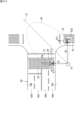
- FIG. 5B is a diagram showing a second example of the installation of an infrastructure radio wave sensor according to an embodiment.
- the infrastructure radio wave sensor 10 is installed at an inclined angle with respect to the longitudinal direction of the crosswalk 20.
- the projection center axis 41 also intersects with the crosswalk 20.
- the radio wave irradiation area 40 includes the entire crosswalk 20.
- Radio waves are emitted radially from the transmitting/receiving surface 104a of the infrastructure radio wave sensor 10.
- the direction of radio wave emission from the infrastructure radio wave sensor 10 includes the longitudinal direction D1 of the crosswalk 20.
- the direction D1 is perpendicular to the traveling direction DT1 of the vehicle 80. Therefore, also in the second example, the line-of-sight velocity of the vehicle 80 becomes zero at point P12 where one of the radio wave emission directions D1 from the infrastructure radio wave sensor 10 and the traveling direction DT1 of the vehicle 80 intersect perpendicularly.
- the line-of-sight velocity of the vehicle 80 transitions from negative to positive during the period including the time when the vehicle 80 reaches this point P12. Therefore, also in the second example, the vehicle detection unit 122 can detect the vehicle 80.
- the area that includes point P12 and extends in the longitudinal direction of the crosswalk 20 is the zero radial velocity area 21.
- D1 which is one of the radio wave irradiation directions, is perpendicular to the traveling direction DT1 of the vehicle 80 on the roadway 60.
- the radial velocity of the vehicle 80 traveling in the direction DT1 is zero.
- FIG. 5C is a diagram showing a third example of the installation of an infrastructure radio wave sensor according to an embodiment.
- the infrastructure radio wave sensor 10 is installed at an inclined angle with respect to the longitudinal direction of the crosswalk 20.
- the projection center axis 41 also intersects with the crosswalk 20.
- the radio wave irradiation area 40 does not include the entire crosswalk 20, and part of the crosswalk 20 is outside the radio wave irradiation area 40.
- a part of road 61 (second road) that intersects road 60 (first road) is included in radio wave irradiation area 40. More specifically, one of the radio wave irradiation directions D2 of infrastructure radio wave sensor 10 is perpendicular to lane direction DT2 at point P20 of road 61 included in radio wave irradiation area 40. Therefore, the line-of-sight velocity of vehicle 80 passing this point P2 also transitions from positive to zero and then to negative. For this reason, in the third example, vehicle detection unit 122 detects not only vehicles 80 traveling on road 60, but also vehicles 80 traveling on road 61.
- the area that includes point P13 and extends in the longitudinal direction of the crosswalk 20 is the zero radial velocity area 21.
- D1 which is one of the radio wave irradiation directions, is perpendicular to the traveling direction DT1 of the vehicle 80 on the roadway 60.
- the radial velocity of the vehicle 80 traveling in the direction DT1 is zero.
- the zero radial velocity area 22 which is an area (but limited to within the radio wave irradiation area 40) that includes point P13 and extends in the direction D2 across the roadway 61
- one of the radio wave irradiation directions D2 is perpendicular to the traveling direction DT2 of the vehicle 80 on the roadway 61.
- the radial velocity of the vehicle 80 traveling in the direction DT2 is zero.
- the vehicle detection unit 122 will count not only vehicles 80 traveling on roadway 60, but also vehicles 80 traveling on roadway 61. For this reason, it is inappropriate to install the infrastructure radio wave sensor 10 at a position and angle such as in the third example.
- the vehicle detection unit 122 can count only vehicles 80 traveling on the roadway 60. For this reason, it is appropriate to install the infrastructure radio wave sensor 10 at a position and angle such as those in the first and second examples.
- the infrastructure radio wave sensor 10 can be installed at a position and angle where the line-of-sight speed of the vehicle 80 is low, the maximum detection speed of the infrastructure radio wave sensor 10 can be reduced and the speed resolution can be increased. For this reason, it is preferable to install the infrastructure radio wave sensor 10 at a position and angle where the line-of-sight speed of the vehicle 80 is close to zero.
- the lane determination unit 123 determines the lane in which the vehicle 80 is traveling based on the distance of the object at the zero crossing point where the line-of-sight velocity transitions from positive to negative or from negative to positive.
- FIG. 7 is a diagram showing an example of the distance between an infrastructure radio wave sensor and a lane.
- FIG. 7 shows an example in which the infrastructure radio wave sensor 10 is installed at a position where the projection center axis 41 is perpendicular to the lane direction DT1 of the roadway 60.
- the distance from the infrastructure radio wave sensor 10 to point P60A is L1.
- the distance from the infrastructure radio wave sensor 10 to point P60B is L2.
- the distance from the infrastructure radio wave sensor 10 to point P60C is L3.
- the distance from the infrastructure radio wave sensor 10 to point P60D is L4.
- Figure 8 is a graph to explain the principle of lane determination.
- Figure 8 shows a two-dimensional spectrum of line-of-sight velocity and distance.
- the vertical axis is line-of-sight velocity
- the horizontal axis is distance.
- the radial velocity of vehicle 80 traveling in direction DT1 on roadway 60 transitions from positive to negative.
- vehicle 80 approaches infrastructure radio wave sensor 10 from a distance, is closest to infrastructure radio wave sensor 10 at the zero crossing point of the radial velocity, and then moves away from infrastructure radio wave sensor 10. Therefore, the distance between infrastructure radio wave sensor 10 and vehicle 80 decreases as the radial velocity approaches zero from a positive value, reaches a minimum value at the zero crossing point of the radial velocity, and increases as the radial velocity further decreases (becomes a negative value).
- the distance at the zero cross point of the line of sight velocity is determined by whether the vehicle 80 is traveling in lane 60A, 60B, 60C, or 60D. If the distance at the zero cross point of the line of sight velocity is L1, the lane determination unit 123 determines that the detected vehicle 80 is traveling in lane 60A. If the distance at the zero cross point of the line of sight velocity is L2, the lane determination unit 123 determines that the detected vehicle 80 is traveling in lane 60B. If the distance at the zero cross point of the line of sight velocity is L3, the lane determination unit 123 determines that the detected vehicle 80 is traveling in lane 60C. If the distance at the zero cross point of the line of sight velocity is L4, the lane determination unit 123 determines that the detected vehicle 80 is traveling in lane 60D.
- a distance range used for lane determination is defined to allow for fluctuations in the positions of vehicles traveling in the same lane and distance measurement errors.
- a distance range of a predetermined width centered on L1 is defined to determine lane 60A.
- a distance range of a predetermined width centered on L2 is defined to determine lane 60B.
- a distance range of a predetermined width centered on L3 is defined to determine lane 60C.
- a distance range of a predetermined width centered on L4 is defined to determine lane 60D.
- the lane determination unit 123 can determine the lane in which the vehicle 80 is traveling depending on which distance range the measured distance falls within at the zero crossing point of the line of sight velocity.
- the infrastructure radio wave sensor 10 detects the vehicle 80 traveling on the roadway 60 by the transition of the line-of-sight velocity. For this reason, the infrastructure radio wave sensor 10 needs to be installed at a position where the line-of-sight velocity of the vehicle 80 changes from positive to negative (or from negative to positive).
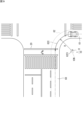
- FIG. 9 is a diagram showing an example of the restricted installation range of the infrastructure radio wave sensor according to the embodiment.
- the travel trajectory of a vehicle 80 turning right or left forms an arc. If an infrastructure radio wave sensor 10 is installed at the center of this arc, the distance between the vehicle 80 and the infrastructure radio wave sensor 10 will be constant while the vehicle 80 is traveling along the arc, and the line-of-sight speed of the vehicle 80 will be zero. Therefore, the infrastructure radio wave sensor 10 cannot detect a vehicle 80 turning right or left at an intersection.
- an installation restriction range is determined.
- the installation restriction range 10N can be set to a range within 10% of the curvature radius R of the center line 62C of the lane 62 from the center of curvature 62O of the arc-shaped lane 62 that connects the roadway 61 to the roadway 60.
- FIG. 9 shows an example of an installation restriction range corresponding to a left-turn lane at an intersection on a left-hand traffic road, but this is not limited to this.
- An installation restriction range corresponding to a right-turn lane at an intersection on a left-hand traffic road may be set, an installation restriction range corresponding to a right-turn lane at an intersection on a right-hand traffic road may be set, or an installation restriction range corresponding to a left-turn lane at an intersection on a right-hand traffic road may be set.
- the measurement unit 121 generates reflected wave data based on the acquired distance and azimuth angle information.
- the measurement unit 121 outputs the generated reflected wave data to the pedestrian detection unit 124.
- the pedestrian detection unit 124 extracts reflection points, which are peak points contained in the reflected wave data.
- the reflected wave data includes data indicating the waveform of the reflected wave for distance and data indicating the waveform of the reflected wave for angle.
- the pedestrian detection unit 124 extracts peak points from each of the waveform of the reflected wave for distance and the waveform of the reflected wave for angle.
- the pedestrian detection unit 124 determines the reflection points by associating the peak points in the reflected wave for distance with the peak points in the reflected wave for angle.
- the radio waves emitted from the infrastructure radio wave sensor 10 may be reflected by multiple objects at the same time.
- the pedestrian detection unit 124 groups reflection points on the same object in the detection area 30.
- the pedestrian detection unit 124 identifies the position of the object (pedestrian) based on the reflected waves received by the receiving antenna 106a.
- the position of the object is expressed as a coordinate value in a coordinate system defined inside the infrastructure radio wave sensor 10.
- the measurement unit 121 determines a representative value of the reflection points belonging to the same group, and sets the determined representative value to the position of the object.
- the representative value is the center of gravity.
- the position of the object may be a representative value other than the center of gravity of multiple reflection points.
- the representative value may be the average value of the reflection points, or the median value of the reflection points.
- the tracking unit 125 tracks the detected objects (pedestrians). Specifically, the tracking unit 125 assigns an ID to each object detected by the pedestrian detection unit 124. The pedestrian detection unit 124 outputs the detection results of the object's position and line-of-sight speed at regular time intervals. The tracking unit 125 identifies the currently detected objects that are the same as the previously detected object. For example, the tracking unit 125 estimates the current position of object a based on the previous movement direction and speed of object a. Among the currently detected objects, the tracking unit 125 identifies the object closest to the position estimated from the previous movement direction and speed of object a as object a. An object identified as the same as the previously detected object inherits the ID of the previously detected object.
- the lane determination unit 123 outputs information about detected vehicles. Specifically, the lane determination unit 123 outputs the counting result of the number of vehicles per lane (count value per unit time).
- the tracking unit 125 outputs information about detected pedestrians. Specifically, the tracking unit 125 outputs the position (distance and azimuth), speed, and ID of the pedestrian.
- the information (detection data) output from the lane determination unit 123 and the tracking unit 125 is provided to the communication interface 107.
- the communication interface 107 transmits the detection data to, for example, a server, a traffic light control device, or surrounding vehicles.
- FIG. 10 is a flowchart showing an example of the operation of an infrastructure radio wave sensor according to an embodiment.
- the infrastructure radio wave sensor 10 emits radio waves from the transmitting antenna 105a.
- the radio wave irradiation area 40 includes the crosswalk 20 and a part of the roadway 60 that crosses the crosswalk 20.
- the radio waves transmitted from the transmitting antenna 105a are reflected by pedestrians on the crosswalk 20 or vehicles 80 on the roadway 60.
- the reflected waves are received by the receiving antenna 106a.
- the transmitter/receiver 104 outputs to the detection circuit 120 the transmission signal (modulated wave signal) from the transmitting antenna 105a and the reception signal (reflected wave signal) from the receiving antenna 106a.
- the processor 101 combines the modulated wave signal and the reflected wave signal to generate an IF signal.
- the processor 101 extracts reflection points from the waveform of the reflected wave.
- the processor 101 performs a fast Fourier transform on the IF signal to measure the distance to the object, the radial velocity of the object, and the azimuth angle (step S101).
- the processor 101 monitors the radial velocity of each object (reflection point) and detects an object whose radial velocity transitions from negative to positive as a vehicle 80 traveling on the roadway 60 (step S102).
- the processor 101 determines the lane in which the vehicle 80 is traveling based on the distance to the detected vehicle 80 (step S103).
- the processor 101 counts the number of vehicles detected per lane per unit time (step S104).
- the processor 101 groups the reflection points and detects each group of reflection points within the detection area 30 as a pedestrian (step S105).
- the processor 101 assigns an ID to the detected pedestrian and executes a tracking process for the detected pedestrian (step S106).
- the tracking process identifies the chronological position of the pedestrian.
- the processor 101 causes the communication interface 107 to transmit the detection data, including the counting results of the vehicles 80, the pedestrian's position, the pedestrian's speed, and the pedestrian's ID, to an external device (a server, a traffic signal control device, or a surrounding vehicle) (step S107). After transmitting the detection data, the processor 101 returns to step S101.
- an external device a server, a traffic signal control device, or a surrounding vehicle
- the measurement of the distance, radial velocity, and azimuth angle of the object is performed by software processing of the processor 101.
- the processing of the modulated wave signal and the reflected wave signal and the measurement of the distance, radial velocity, and azimuth angle of the object may be performed by hardware, for example, a signal processing circuit provided separately from the processor 101.
Landscapes
- Engineering & Computer Science (AREA)
- Radar, Positioning & Navigation (AREA)
- Remote Sensing (AREA)
- Physics & Mathematics (AREA)
- General Physics & Mathematics (AREA)
- Computer Networks & Wireless Communication (AREA)
- Electromagnetism (AREA)
- Traffic Control Systems (AREA)
- Radar Systems Or Details Thereof (AREA)
Abstract
電波センサは、横断歩道の少なくとも一部を含む電波照射エリアに電波を照射することにより、前記電波照射エリアにおける物体を検知する電波センサであって、前記電波照射エリアに電波を照射する送信アンテナと、前記送信アンテナから照射された電波の前記物体による反射波を受信する受信アンテナと、前記送信アンテナから照射された前記電波と、前記受信アンテナによって受信された反射波とに基づいて、前記電波センサと前記物体とを結ぶ直線方向の速度である前記物体の視線速度を測定する測定部と、前記測定部によって測定された前記視線速度がゼロになる物体を特定することにより、前記横断歩道を横切る車道を走行する車両を検知する車両検知部と、を備える。
Description
本開示は、電波センサ、検知方法、及び検知プログラムに関する。本出願は、2023年7月4日出願の日本出願第2023-109960号に基づく優先権を主張し、前記日本出願に記載された全ての内容を援用するものである。
特許文献1には、3次元座標軸における目標と誤検出との密度分布の差異によるクラスタ分析により、誤検出を抑圧し、目標のみを抽出するレーダ装置が開示されている。
本開示の一態様に係る電波センサは、横断歩道を含む電波照射エリアに電波を照射することにより、前記電波照射エリアにおける物体を検知する電波センサであって、前記電波照射エリアに電波を照射する送信アンテナと、前記送信アンテナから照射された電波の前記物体による反射波を受信する受信アンテナと、前記送信アンテナから照射された前記電波と、前記受信アンテナによって受信された反射波とに基づいて、前記電波センサと前記物体とを結ぶ直線方向の速度である前記物体の視線速度を測定する測定部と、前記測定部によって測定された前記視線速度がゼロになる物体を特定することにより、前記横断歩道を横切る車道を走行する車両を検知する車両検知部と、を備える。
<本開示が解決しようとする課題>
電波センサは、物体と電波センサとを結ぶ直線方向の物体の速度(以下、「視線速度」ともいう)を検知することができる。この速度の検知について、検知可能な速度の上限である最大検知速度と、速度分解能とはトレードオフの関係にある。したがって、例えば、車両と歩行者のような速度差が大きい2種類の物体を検知対象とする場合、速度の高い車両を検知するために最大検知速度を大きくすると、速度分解能が低下して、低速な歩行者の速度を正確に検知できなくなる。一方、歩行者の速度を正確に検知するために速度分解能を高くすると、最大検知速度が低くなり車両の速度を正確に検知できなくなる。
電波センサは、物体と電波センサとを結ぶ直線方向の物体の速度(以下、「視線速度」ともいう)を検知することができる。この速度の検知について、検知可能な速度の上限である最大検知速度と、速度分解能とはトレードオフの関係にある。したがって、例えば、車両と歩行者のような速度差が大きい2種類の物体を検知対象とする場合、速度の高い車両を検知するために最大検知速度を大きくすると、速度分解能が低下して、低速な歩行者の速度を正確に検知できなくなる。一方、歩行者の速度を正確に検知するために速度分解能を高くすると、最大検知速度が低くなり車両の速度を正確に検知できなくなる。
<本開示の効果>
本開示によれば、速度差が大きい複数種類の物体を電波センサの検知対象とすることができる。
本開示によれば、速度差が大きい複数種類の物体を電波センサの検知対象とすることができる。
<本開示の実施形態の概要>
以下、本開示の実施形態の概要を列記して説明する。
以下、本開示の実施形態の概要を列記して説明する。
(1) 本実施形態に係る電波センサは、横断歩道の少なくとも一部を含む電波照射エリアに電波を照射することにより、前記電波照射エリアにおける物体を検知する電波センサであって、前記電波照射エリアに電波を照射する送信アンテナと、前記送信アンテナから照射された電波の前記物体による反射波を受信する受信アンテナと、前記送信アンテナから照射された前記電波と、前記受信アンテナによって受信された反射波とに基づいて、前記電波センサと前記物体とを結ぶ直線方向の速度である前記物体の視線速度を測定する測定部と、前記測定部によって測定された前記視線速度がゼロになる物体を特定することにより、前記横断歩道を横切る車道を走行する車両を検知する車両検知部と、を備える。これにより、横断歩道を横切る車道を走行する車両の視線速度を走行速度よりも低くすることができる。したがって、最大検知速度を低く設定することができ、横断歩道の歩行者と車両とを電波センサの検知対象とすることができる。
(2) 上記(1)において、前記送信アンテナ及び前記受信アンテナの前方に配置され、前記電波照射エリアへ前記電波を照射し、前記反射波を受信する送受信面をさらに備え、前記送受信面の中心から前記送受信面の法線を鉛直方向へ地表に投影させた投影中心軸が、前記横断歩道に交差してもよい。これにより、横断歩道の多くの部分を電波照射エリアに含めることができる。
(3) 上記(2)において、前記電波照射エリア内において、前記横断歩道を横切る前記車道の車線方向が、前記送受信面から照射される前記電波の照射方向の1つと直交してもよい。これにより、車道において、車線方向と電波の照射方向の1つとが直交する地点における車両の視線速度がゼロになり、車両の視線速度を抑制することができる。
(4) 上記(2)又は(3)において、前記投影中心軸と前記車道とが交差する地点における前記車両の前記視線速度が、前記車両の走行速度の50%以下であってもよい。これにより、車両の視線速度を抑制することができる。
(5) 上記(1)から(4)のいずれか1つにおいて、前記車両検知部は、前記測定部によって測定された前記視線速度が正から負へ又は負から正へ推移する物体を特定することにより、前記車道を走行する前記車両を検知してもよい。これにより、車道を走行する車両を正確に検知することができる。
(6) 上記(1)から(5)のいずれか1つにおいて、前記測定部は、前記送信アンテナから照射された前記電波と、前記受信アンテナによって受信された反射波とに基づいて、前記電波センサから前記物体までの距離を測定し、前記電波センサは、前記視線速度が正から負へ又は負から正へ遷移するゼロクロス点における前記物体の距離に基づいて、前記車両が走行する車線を判定する車線判定部をさらに備えてもよい。これにより、複数の車線を含む車道において、電波センサとゼロクロス点との距離は車線毎に異なる。したがって、距離の測定結果を利用することにより、車両が走行する車線を判定することができる。
(7) 上記(1)から(6)のいずれか1つにおいて、前記横断歩道を横切る前記車道である第1車道に交差する第2車道を前記電波照射エリアに含まなくてもよい。これにより、第2車道を走行する車両を、第1車道を走行する車両と誤検知することを防止することができる。
(8) 上記(1)から(7)のいずれか1つにおいて、前記電波センサは、前記横断歩道を横切る前記車道である第1車道と、前記第1車道とは異なる第2車道との交差点において、前記第1車道から前記第2車道へ又は前記第2車道から前記第1車道へつながる円弧状の車線の曲率中心から、前記車線の中心線の曲率半径の10%以内の範囲に設置されなくてもよい。上記の範囲内に電波センサが設置されると、第1車道から第2車道へ又は第2車道から第1車道へ進入する(すなわち、交差点を右折又は左折する)車両の視線速度はゼロに近くなり、これらの車両を電波センサで検知することができなくなる。したがって、上記の範囲を除外して電波センサを設置することにより、交差点を右折又は左折する車両を電波センサにより検知することができる。
(9) 本実施形態に係る検知方法は、横断歩道を含む電波照射エリアに電波を照射することにより、前記電波照射エリアにおける物体を検知する電波センサによる検知方法であって、送信アンテナから前記電波照射エリアに電波を照射するステップと、前記送信アンテナから照射された電波の前記物体による反射波を受信アンテナにより受信するステップと、前記送信アンテナから照射された前記電波と、前記受信アンテナによって受信された反射波とに基づいて、前記電波センサと前記物体とを結ぶ直線方向の速度である前記物体の視線速度を測定するステップと、測定された前記視線速度がゼロになる物体を特定することにより、前記横断歩道を横切る車道を走行する車両を検知するステップと、を含む。これにより、横断歩道を横切る車道を走行する車両の視線速度を走行速度よりも低くすることができる。したがって、最大検知速度を低く設定することができ、横断歩道の歩行者と車両とを電波センサの検知対象とすることができる。
(10) 本実施形態に係る検知プログラムは、横断歩道を含む電波照射エリアに電波を照射することにより、前記電波照射エリアにおける物体を検知する電波センサにおいて用いられる検知プログラムであって、コンピュータに、送信アンテナから前記電波照射エリアに照射された電波と、前記受信アンテナによって受信された、前記電波の前記物体による反射波とに基づいて測定された、前記電波センサと前記物体とを結ぶ直線方向の速度である前記物体の視線速度を取得するステップと、取得された前記視線速度がゼロになる物体を特定することにより、前記横断歩道を横切る車道を走行する車両を検知するステップと、実行させる。これにより、横断歩道を横切る車道を走行する車両の視線速度を走行速度よりも低くすることができる。したがって、最大検知速度を低く設定することができ、横断歩道の歩行者と車両とを電波センサの検知対象とすることができる。
本開示は、上記のような特徴的な構成を備える電波センサ、特徴的な処理をステップとする電波センサの検知方法、及び、電波センサに特徴的な処理を実行させるための検知プログラムとして実現することができるだけでなく、電波センサの一部を半導体集積回路として実現したり、電波センサを含むシステムとして実現したりすることができる。
<本開示の実施形態の詳細>
以下、図面を参照しつつ、本発明の実施形態の詳細を説明する。なお、以下に記載する実施形態の少なくとも一部を任意に組み合わせてもよい。
以下、図面を参照しつつ、本発明の実施形態の詳細を説明する。なお、以下に記載する実施形態の少なくとも一部を任意に組み合わせてもよい。
[1.インフラ電波センサ]
図1は、実施形態に係るインフラ電波センサの使用例を示す図である。本実施形態に係るインフラ電波センサ10は、交通監視用の電波レーダであり、横断歩道20における物体(歩行者、自転車(搭乗者含む)、車両)を検知する。インフラ電波センサ10は、例えばミリ波レーダである。
図1は、実施形態に係るインフラ電波センサの使用例を示す図である。本実施形態に係るインフラ電波センサ10は、交通監視用の電波レーダであり、横断歩道20における物体(歩行者、自転車(搭乗者含む)、車両)を検知する。インフラ電波センサ10は、例えばミリ波レーダである。
インフラ電波センサ10は、道路に設けられた構造物50に取り付けられる。構造物50は、数mの高さを有しており、インフラ電波センサ10は地上数mの高さに設置される。構造物50は、例えば、ポール51と、ポール51の上端付近に設けられたアーム52とを含み、アーム52にインフラ電波センサ10が取り付けられる。
一般的な交通監視用の電波センサは、車道を走行する車両を検知するために、車道の直上から車線方向(車両の走行方向)前方の車道上の一点にセンサ正面を向けるように設置される。これに対して、本実施形態に係るインフラ電波センサ10は、横断歩道20上に電波(ミリ波)を照射し、その反射波を受信することで横断歩道20上の物体(例えば、歩行者、自転車)と、横断歩道20を横切る車道60を走行する車両とを検知する。さらに具体的には、インフラ電波センサ10は、インフラ電波センサ10から物体までの距離、物体の速度(インフラ電波センサ10と物体とを結ぶ直線方向の速度。以下「視線速度」ともいう。)、及びインフラ電波センサ10の正面方向に対する物体が存在する位置の水平角度(方位角)を検知することができる。
インフラ電波センサ10では、物体を検知するための道路上の範囲である検知エリア30が設定される。検知エリア30は、インフラ電波センサ10の電波照射エリア40の一部として設定される。つまり、電波照射エリア40は検知エリア30をカバーする。インフラ電波センサ10が横断歩道20全体の交通状況を監視するためには、横断歩道20の全体を含む検知エリア30が設定されることが好ましい。なお、電波照射エリア40は、インフラ電波センサ10が照射した電波を物体が反射し、物体からの反射波によってインフラ電波センサ10が物体を検知可能な範囲であり、電波を照射可能であってもインフラ電波センサ10が物体を検知することができない範囲は含まれない。ただし、電波照射エリア40はこれに限られず、インフラ電波センサ10が電波を照射可能な範囲全体であってもよい。
例えば、横断歩道20を通行する歩行者及び自転車(搭乗者含む。以下、歩行者及び自転車を単に「歩行者」という)の通行量の計測、又は、横断歩道20に設置された交通信号機の制御に用いられるインフラ電波センサ10では、横断歩道上の通行者だけでなく、横断歩道20に隣接する歩道上で横断を待機する通行者も検知することが要求される。このため、例えば、検知エリア30は、横断歩道20のエリアだけでなく、歩道上で通行者が横断を待機するためのエリアを含む。すなわち、検知エリア30は、横断歩道20から、横断歩道20の長手方向(歩行者が横断歩道上を通行する方向)の両側へ拡張されたエリアである。
[2.インフラ電波センサのハードウェア構成]
図2は、実施形態に係るインフラ電波センサ10の外観構成の一例を示す斜視図である。図2に示すように、インフラ電波センサ10は、電波を送受信する送受信面140aを一面に有する筐体140を含む。筐体140は、送受信部104及び検知回路120を収容する。送受信部104は、送信アンテナ105aと複数(例えば4つ)の受信アンテナ106aとを含む。インフラ電波センサ10は、送信アンテナ105aから送受信面140aを通じて電波である変調波を送信する。変調波は物体に当たり反射し、受信アンテナ106aが反射波を受信する。送受信部104及び検知回路120は、送信波信号及び受信波信号に対して信号処理を施し、物体までの距離、物体の視線速度、及び物体が存在する方位角を検知する。
図2は、実施形態に係るインフラ電波センサ10の外観構成の一例を示す斜視図である。図2に示すように、インフラ電波センサ10は、電波を送受信する送受信面140aを一面に有する筐体140を含む。筐体140は、送受信部104及び検知回路120を収容する。送受信部104は、送信アンテナ105aと複数(例えば4つ)の受信アンテナ106aとを含む。インフラ電波センサ10は、送信アンテナ105aから送受信面140aを通じて電波である変調波を送信する。変調波は物体に当たり反射し、受信アンテナ106aが反射波を受信する。送受信部104及び検知回路120は、送信波信号及び受信波信号に対して信号処理を施し、物体までの距離、物体の視線速度、及び物体が存在する方位角を検知する。
図3は、実施形態に係るインフラ電波センサのハードウェア構成の一例を示すブロック図である。インフラ電波センサ10は、送受信部104と、検知回路120とを含む。
検知回路120は、プロセッサ101と、不揮発性メモリ102と、揮発性メモリ103と、通信インタフェース107とを含む。
送受信部104は、送信回路105と、受信回路106とを含む。
送信回路105は、送信アンテナ105aを含む。なお、送信アンテナ105aの数は1つに限られず、複数であってもよい。送信回路105は、変調波を生成し、生成された変調波を送信アンテナ105aから送信する。
受信回路106は、受信アンテナ106aを含む。物体の方位角を検知するために、複数(図では4つ)の受信アンテナ106aが設けられる。受信回路106は、受信された反射波に対して信号処理を施す。信号処理によって生成された反射波データは、プロセッサ101に与えられる。プロセッサ101は、反射波データを解析し、物体の位置(距離及び方位角)並びに視線速度を検知する。
揮発性メモリ103は、例えばSRAM(Static Random Access Memory)、DRAM(Dynamic Random Access Memory)等の半導体メモリである。不揮発性メモリ102は、例えばフラッシュメモリ、ハードディスク、ROM(Read Only Memory)等である。不揮発性メモリ102には、コンピュータプログラムである検知プログラム110及び検知プログラム110の実行に使用されるデータが格納される。インフラ電波センサ10の各機能は、検知プログラム110がプロセッサ101によって実行されることで発揮される。検知プログラム110は、フラッシュメモリ、ROM、CD-ROMなどの記録媒体に記憶させることができる。プロセッサ101は、検知プログラム110によって、物体の位置(距離及び方位角)並びに視線速度を検知することができる。
プロセッサ101は、例えばCPU(Central Processing Unit)である。ただし、プロセッサ101は、CPUに限られない。プロセッサ101は、GPU(Graphics Processing Unit)であってもよい。プロセッサ101は、例えば、ASIC(Application Specific Integrated Circuit)であってもよいし、FPGA(Field Programmable Gate Array)等のプログラマブルロジックデバイスであってもよい。この場合、ASIC又はプログラマブルロジックデバイスは、検知プログラム110と同じ処理を実行可能に構成される。
通信インタフェース107は外部の装置と通信することができる。例えば、通信インタフェース107は、無線通信インタフェースであり、道路交通情報センタ等によって運用されるサーバ、横断歩道20を含む交差点に設置された交通信号機を制御するための制御装置、又は、インフラ電波センサ10の周囲の車両(に搭載された車載装置)へ検知結果のデータ(以下、「検知データ」ともいう)を送信することができる。
[3.インフラ電波センサの機能]
図4は、実施形態に係るインフラ電波センサの機能の一例を示す機能ブロック図である。プロセッサ101が検知プログラム110を実行することにより、インフラ電波センサ10は、測定部121と、車両検知部122と、車線判定部123と、歩行者検知部124と、追跡部125として機能する。
図4は、実施形態に係るインフラ電波センサの機能の一例を示す機能ブロック図である。プロセッサ101が検知プログラム110を実行することにより、インフラ電波センサ10は、測定部121と、車両検知部122と、車線判定部123と、歩行者検知部124と、追跡部125として機能する。
測定部121は、送信アンテナ105aから照射された電波と、受信アンテナ106aによって受信された反射波とに基づいて、物体の視線速度を測定する。
測定部121は、送信アンテナ105aから照射された電波と、受信アンテナ106aによって受信された反射波とに基づいて、インフラ電波センサ10から物体までの距離を測定する。さらに測定部121は、送信アンテナ105aから照射された電波と、受信アンテナ106aによって受信された反射波とに基づいて、送受信面104aの中心から送受信面104aの法線を鉛直方向へ地表に投影させた直線(以下、「投影中心軸」ともいう)に対する物体の角度(方位角)を測定する。
具体的には、測定部121は、反射波の信号レベルを含む情報を、電波が照射された位置毎に示す反射波データを生成する。送信回路105は、送信アンテナ105aから変調波である送信信号を送信する。送信アンテナ105aからの送信信号は物体に当たって反射する。受信アンテナ106aは、物体からの反射波を受信する。測定部121は、送信回路105から出力される変調波信号と、受信回路106から出力される反射波信号とを合成し、中間周波数信号(以下、「IF信号」という)を生成する。測定部121は、IF信号に対して高速フーリエ変換(FFT)を施し、距離、視線速度及び方位角の情報を取得する。
具体的には、送信アンテナ105aからは、送信信号(チャープ)が一定間隔で送信される。移動中の物体は、異なる2点において送信信号を反射し、受信アンテナ106aは各反射波を受信する。測定部121は、移動中の物体から得られた複数のIF信号の位相差から物体の視線速度を測定する。
測定部121によって測定された視線速度は、測定部121から車両検知部122へ出力される。車両検知部122は、測定部121によって測定された視線速度がゼロになる物体を特定することにより、横断歩道20を横切る車道60を走行する車両を検知する。
図5Aは、実施形態に係るインフラ電波センサの設置の第1例を示す図である。
横断歩道20を横切る車道60の両側には、歩道70A,70Bが設けられている。インフラ電波センサ10は、投影中心軸41が、横断歩道20に交差する位置及び角度で歩道70Aに設置される。なお、ここでいう、「投影中心軸41が横断歩道20に交差する」とは、投影中心軸41が横断歩道20に重なっていることを意味する。
図5Aに示す例では、投影中心軸41が、横断歩道20の長手方向と平行であり、横断歩道20の幅方向の概略中心を通る位置及び角度でインフラ電波センサ10が設置されている。この第1例では、電波照射エリア40に、横断歩道20の全体が含まれている。
横断歩道20を横切る車道60には、インフラ電波センサ10に近い順に、車線60A,60B,60C,60Dが設けられている。車線60A及び60Bは、図において右から左へと車両80が走行するための車線である。車線60C及び60Dは、図において左から右へと車両80が走行するための車線である。
電波照射エリア40内において、横断歩道20を横切る車道60の車線方向が、送受信面104aから照射される電波の照射方向の1つと直交するように、インフラ電波センサ10は設置される。図5Aに示す第1例では、電波の照射方向の1つD1に沿って延びる投影中心軸41と、車道60における車両80の走行方向(すなわち、車道60における車線方向)DT1とが車道60上の地点P11において直交する。
図6は、実施形態に係るインフラ電波センサによる車両検知を説明するための図である。
上述したように、測定部121は物体の視線速度を測定する。車両検知部122は、測定部121によって測定された視線速度に基づいて車両を検知する。図6において、車両80は右から左へと速度Vで走行する。
車両80が、投影中心軸41から右方に角度θ1の地点P1にあるとき、車両80の視線速度の大きさはVcos(π/2-θ1)である。ここで、インフラ電波センサ10に近づく方向の視線速度の符号を負とし、インフラ電波センサ10から遠ざかる方向の視線速度の符号を正とする。この場合、地点P1における車両80の視線速度は-Vcos(π/2-θ1)である。
投影中心軸41上の地点P2では、投影中心軸41と車両80の走行方向とは直交する。したがって、車両80が地点P2にあるとき、車両80の視線速度はゼロである。
車両80が、投影中心軸41から左方に角度θ2の地点P3にあるとき、車両80の視線速度は+Vcos(π/2-θ2)である。
このように、車両80が地点P1,P2,P3の順で通過するように走行した場合、地点P2において車両80の視線速度はゼロになる。車両検知部122は、このように視線速度がゼロになる物体を車両80として検知する。
さらに具体的には、車両検知部122は、測定部121によって測定された視線速度が正から負へ又は負から正へ遷移する物体を特定することにより、車道60を走行する車両80を検知する。すなわち、車両検知部122は、視線速度の符号が正から負へ、又は負から正へ切り替わる物体を車両80として検知する。
なお、視線速度が正から負へ遷移するか、負から正へ遷移するかは、視線速度の符号の割り当て方によって定まる。すなわち、本実施形態のように、インフラ電波センサ10に近づく方向の視線速度の符号を負とし、インフラ電波センサ10から遠ざかる方向の視線速度の符号を正とする場合、視線速度は負から正へと変化する。一方、インフラ電波センサ10に近づく方向の視線速度の符号を正とし、インフラ電波センサ10から遠ざかる方向の視線速度の符号を負とする場合、視線速度は正から負へと変化する。
図5Aに戻り、第1例では、地点P11を含み、横断歩道20の長手方向(すなわち、車道60の車線方向DT1に直行する方向。第1例では投影中心軸41の方向D1)へ延びるエリアである視線速度ゼロエリア21において、投影中心軸41と、車道60における車両80の走行方向DT1とが直交する。つまり、視線速度ゼロエリア21内のどの位置においても、方向DT1へ走行する車両80の視線速度はゼロになる。
例えば、車両検知部122は、視線速度が正から負へ(又は負から正へ)遷移した物体の数を計数することにより、車道60を走行する車両を計数する。具体的な一例では、車両検知部122は、単位時間(例えば1分間)に車両80を走行する車両を計数する。
図5Bは、実施形態に係るインフラ電波センサの設置の第2例を示す図である。
図5Bの例では、インフラ電波センサ10は、横断歩道20の長手方向に対して傾斜した角度で設置されている。第2例でも、投影中心軸41は、横断歩道20に交差している。第2例では、電波照射エリア40に、横断歩道20の全体が含まれている。
インフラ電波センサ10の送受信面104aからは、放射状に電波が照射される。第2例において、インフラ電波センサ10からの電波照射方向は、横断歩道20の長手方向D1を含んでいる。方向D1は、車両80の走行方向DT1と直交する。したがって、第2例においても、インフラ電波センサ10からの電波照射方向の1つD1と車両80の走行方向DT1とが直交する地点P12において、車両80の視線速度はゼロになる。すなわち、車両80がこの地点P12に到達する時点を含む期間において、車両80の視線速度は負から正へ推移する。このため、第2例においても、車両検知部122は車両80を検知することができる。
第2例では、地点P12を含み、横断歩道20の長手方向へ延びるエリアが視線速度ゼロエリア21である。第2例において、視線速度ゼロエリア21では、電波照射方向の1つであるD1と、車道60における車両80の走行方向DT1とが直交する。つまり、視線速度ゼロエリア21内のどの位置においても、方向DT1へ走行する車両80の視線速度はゼロになる。
図5Cは、実施形態に係るインフラ電波センサの設置の第3例を示す図である。
図5Cの例では、インフラ電波センサ10は、横断歩道20の長手方向に対して傾斜した角度で設置されている。第3例でも、投影中心軸41は、横断歩道20に交差している。ただし、第3例では、電波照射エリア40に、横断歩道20の全体は含まれておらず、横断歩道20の一部は電波照射エリア40から外れている。
第3例では、車道60(第1車道)に交差する車道61(第2車道)の一部が電波照射エリア40に含まれている。さらに具体的には、インフラ電波センサ10の電波照射方向の1つD2が、電波照射エリア40に含まれる車道61の地点P20において、車線方向DT2と直交している。したがって、この地点P2を通過する車両80についても、視線速度は正からゼロを経て負へと推移する。このため、第3例では、車両検知部122は、車道60を走行する車両80だけでなく、車道61を走行する車両80も検知する。
第3例では、地点P13を含み、横断歩道20の長手方向へ延びるエリアが視線速度ゼロエリア21である。第3例において、視線速度ゼロエリア21では、電波照射方向の1つであるD1と、車道60における車両80の走行方向DT1とが直交する。つまり、視線速度ゼロエリア21内のどの位置においても、方向DT1へ走行する車両80の視線速度はゼロになる。
これに加えて、第3例では、地点P13を含み、車道61を横切る方向D2へ延びるエリア(ただし、電波照射エリア40内に限る)である視線速度ゼロエリア22において、電波照射方向の1つD2と、車道61における車両80の走行方向DT2とが直交する。つまり、視線速度ゼロエリア22内のどの位置においても、方向DT2へ走行する車両80の視線速度はゼロになる。
例えば、車道60を走行する車両80を計数することが要求される場合、第3例では、車両検知部122は、車道60を走行する車両80だけでなく、車道61を走行する車両80も計数してしまう。このため、第3例のような位置及び角度にインフラ電波センサ10を設置することは不適切である。
その一方で、第1例及び第2例では、電波照射エリア40内において、いずれの電波照射方向も車道61の車線方向DT2に直交しない。特に、第1例では、電波照射エリア40内に、車道61が含まれない。このため、車道61を走行する車両80は検知されず、車道61を走行する車両が計数されることはない。つまり、第1例及び第2例の場合、車両検知部122は、車道60を走行する車両80のみを計数することができる。このため、第1例及び第2例のような位置及び角度にインフラ電波センサ10を設置することは適切である。
車両80の視線速度が低ければ、車両80の視線速度と歩行者の移動速度との差が小さくなる。したがって、車両80の視線速度が低くなる位置及び角度にインフラ電波センサ10を設置することができれば、インフラ電波センサ10の最大検知速度を小さくし、速度分解能を高めることができる。このため、車両80の視線速度がゼロに近くなる位置及び角度にインフラ電波センサ10を設置することが好ましい。
例えば、投影中心軸41と車道60とが交差する地点における車両80の視線速度が、車両80の走行速度の50%以下である位置及び角度に、インフラ電波センサ10は設置される。車道60の車線方向DT1と投影中心軸41との間の角度が60°以上90°以下である場合、車道60と投影中心軸41とが交差する地点における車両80の視線速度は、車両80の走行速度の50%以下である。したがって、インフラ電波センサ10を、車道60の車線方向DT1と投影中心軸41との間の角度が60°以上90°以下となる位置及び角度に設置してもよい。
図4に戻り、車線判定部123は、視線速度が正から負へ又は負から正へ遷移するゼロクロス点における物体の距離に基づいて、車両80が走行する車線を判定する。
図7は、インフラ電波センサと車線との距離の一例を示す図である。図7には、投影中心軸41が車道60の車線方向DT1と直交する位置にインフラ電波センサ10が設置されている例を示している。
上述したように、視線速度ゼロエリア21内のいずれの位置においても、車道60を走行する車両80の視線速度はゼロになる。すなわち、視線速度ゼロエリア21は、ゼロクロス点の集合エリアである。視線速度ゼロエリア21と車線60Aとが重なる地点P60Aにおいて、車線60Aを走行する車両80の視線速度はゼロになる。視線速度ゼロエリア21と車線60Bとが重なる地点P60Bにおいて、車線60Bを走行する車両80の視線速度はゼロになる。視線速度ゼロエリア21と車線60Cとが重なる地点P60Cにおいて、車線60Cを走行する車両80の視線速度はゼロになる。視線速度ゼロエリア21と車線60Dとが重なる地点P60Dにおいて、車線60Aを走行する車両80の視線速度はゼロになる。
図7において、インフラ電波センサ10から地点P60Aまでの距離はL1である。インフラ電波センサ10から地点P60Bまでの距離はL2である。インフラ電波センサ10から地点P60Cまでの距離はL3である。インフラ電波センサ10から地点P60Dまでの距離はL4である。このように、車線60A,60B,60C,60Dによって、車両80の視線速度がゼロになる位置とインフラ電波センサ10との距離は異なる。
図8は、車線の判定原理を説明するためのグラフである。図8には、視線速度と距離との二次元スペクトルが示される。図8において、縦軸は視線速度であり、横軸は距離である。
上述したように、車道60を方向DT1へ走行する車両80の視線速度は、正から負へと遷移する。この際、車両80は、遠方からインフラ電波センサ10へ近づき、視線速度のゼロクロス点においてインフラ電波センサ10に最も近接し、その後インフラ電波センサ10から遠ざかる。したがって、インフラ電波センサ10と車両80との距離は、視線速度が正の値からゼロに近づくにしたがって小さくなり、視線速度のゼロクロス点において最小値となり、視線速度がさらに減少する(負の値となる)にしたがって大きくなる。
視線速度のゼロクロス点における距離は、車両80が車線60A,60B,60C,60Dのいずれを走行するかによって定まる。車線判定部123は、視線速度のゼロクロス点における距離がL1である場合、検知された車両80は車線60Aを走行していると判定する。車線判定部123は、視線速度のゼロクロス点における距離がL2である場合、検知された車両80は車線60Bを走行していると判定する。車線判定部123は、視線速度のゼロクロス点における距離がL3である場合、検知された車両80は車線60Cを走行していると判定する。車線判定部123は、視線速度のゼロクロス点における距離がL4である場合、検知された車両80は車線60Dを走行していると判定する。
具体的には、同一車線を走行する車両の位置のゆらぎ、及び距離の測定誤差を許容するために、車線判定に用いられる距離範囲が定められる。例えば、車線60Aを判定するために、L1を中心とした所定幅の距離範囲が定められる。車線60Bを判定するために、L2を中心とした所定幅の距離範囲が定められる。車線60Cを判定するために、L3を中心とした所定幅の距離範囲が定められる。車線60Dを判定するために、L4を中心とした所定幅の距離範囲が定められる。車線判定部123は、視線速度のゼロクロス点において、測定距離がいずれの距離範囲に入るかによって、車両80が走行する車線を判定することができる。
上述したように、実施形態に係るインフラ電波センサ10は、視線速度の遷移によって車道60を走行する車両80を検知する。このため、車両80の視線速度が正から負へ(又は負から正へ)変化する位置に、インフラ電波センサ10が設置されている必要がある。
車両80の検知を確実にするため、インフラ電波センサ10の設置位置を制限される範囲(以下、「設置制限範囲」ともいう)が設定されてもよい。図9は、実施形態に係るインフラ電波センサの設置制限範囲の一例を示す図である。
複数の車道が交差する交差点において、右折又は左折する車両80の走行軌跡は円弧状になる。この円弧の中心にインフラ電波センサ10が設置された場合、車両80が円弧に沿って走行している間、車両80とインフラ電波センサ10との距離は一定となり、車両80の視線速度はゼロとなる。したがって、インフラ電波センサ10は、交差点を右折又は左折する車両80を検知できない。
このような車両80の検知不良を生じさせないために、設置制限範囲が定められる。具体的な一例では、横断歩道20を横切る車道60(第1車道)と、車道60とは異なる車道61(第2車道)との交差点において、車道61から車道60へつながる円弧状の車線62の曲率中心62Oから、車線62の中心線62Cの曲率半径Rの10%以内の範囲を設置制限範囲10Nとすることができる。なお、図9には、左側通行の道路における交差点の左折車線に対応した設置制限範囲の例を示したが、これに限定されない。左側通行道路における交差点の右折車線に対応した設置制限範囲を設定してもよいし、右側通行道路における交差点の右折車線に対応した設置制限範囲を設定してもよいし、右側通行道路における交差点の左折車線に対応した設置制限範囲を設定してもよい
図4に戻り、測定部121は、取得した距離及び方位角の情報に基づいて反射波データを生成する。測定部121は、生成した反射波データを歩行者検知部124へ出力する。
歩行者検知部124は、反射波データに含まれるピーク点である反射点を抽出する。反射波データには、距離についての反射波の波形を示すデータ及び角度についての反射波の波形を示すデータが含まれる。歩行者検知部124は、距離についての反射波の波形及び角度についての反射波の波形のそれぞれから、ピーク点を抽出する。歩行者検知部124は、距離についての反射波におけるピーク点と角度についての反射波におけるピーク点とを対応付けることによって、反射点を決定する。
インフラ電波センサ10から照射される電波は、複数の物体によって同時に反射される場合がある。歩行者検知部124は、検知エリア30内の同一の物体における反射点をグループ化する。歩行者検知部124は、受信アンテナ106aによって受信された反射波に基づいて物体(歩行者)の位置を特定する。物体の位置は、インフラ電波センサ10の内部で定義された座標系における座標値として表される。具体的には、測定部121は、同一のグループに属する反射点の代表値を決定し、決定された代表値を物体の位置に設定する。例えば、代表値は重心である。ただし、物体の位置は複数の反射点の重心以外の代表値であってもよい。例えば、代表値は反射点の平均値であってもよいし、反射点の中央値であってもよい。
追跡部125は、検知された物体(歩行者)を追跡する。具体的には、追跡部125は、歩行者検知部124によって検知された各物体にIDを付与する。歩行者検知部124からは、一定の時間間隔毎に物体の位置及び視線速度の検知結果が出力される。追跡部125は、今回検知された物体のうち、前回検知された物体と同じ物体を識別する。例えば、追跡部125は、前回の物体aの移動方向及び速度に基づいて、物体aの今回の位置を推定する。追跡部125は、今回検知された物体のうち、物体aの前回の移動方向及び速度から推定した位置に最も近い位置の物体を、物体aと識別する。前回検知された物体と同一と識別された物体は、前回検知された物体のIDを引き継ぐ。
車線判定部123は、検知された車両の情報を出力する。具体的には、車線判定部123は、車線毎の車両数の計数結果(単位時間における計数値)を出力する。追跡部125は、検知された歩行者の情報を出力する。具体的には、追跡部125は、歩行者の位置(距離及び方位角)と、速度と、IDとを出力する。車線判定部123及び追跡部125から出力された情報(検知データ)は、通信インタフェース107に与えられる。通信インタフェース107は、例えばサーバ、交通信号機の制御装置、又は周囲の車両に、検知データを送信する。
[4.インフラ電波センサの物体検知動作]
以下、インフラ電波センサ10の物体検知動作について説明する。
以下、インフラ電波センサ10の物体検知動作について説明する。
図10は、実施形態に係るインフラ電波センサの動作の一例を示すフローチャートである。
インフラ電波センサ10は、送信アンテナ105aから電波を照射する。電波照射エリア40には、横断歩道20及び横断歩道20を横切る車道60の一部が含まれる。送信アンテナ105aから送信された電波は、横断歩道20上の歩行者又は車道60上の車両80によって反射される。反射波は、受信アンテナ106aによって受信される。
送受信部104からは、送信アンテナ105aからの送信信号(変調波信号)及び受信アンテナ106aによる受信信号(反射波信号)が検知回路120へ出力される。プロセッサ101は、変調波信号と反射波信号とを合成し、IF信号を生成する。プロセッサ101は、反射波の波形から反射点を抽出する。プロセッサ101は、IF信号に対して高速フーリエ変換を施し、物体までの距離、物体の視線速度及び方位角を測定する(ステップS101)。
プロセッサ101は、各物体(反射点)の視線速度を監視し、視線速度が負から正へ遷移する物体を車道60を走行する車両80として検知する(ステップS102)。
プロセッサ101は、検知された車両80までの距離に基づいて、車両80が走行する車線を判定する(ステップS103)。
プロセッサ101は、単位時間に検知された車両を車線毎に計数する(ステップS104)。
プロセッサ101は、反射点をグループ化し、検知エリア30内の反射点の各グループを歩行者として検知する(ステップS105)。
プロセッサ101は、検知された歩行者にIDを付与し、検知された歩行者の追跡処理を実行する(ステップS106)。追跡処理により歩行者の時系列の位置が特定される。
プロセッサ101は、車両80の計数結果、歩行者の位置、歩行者の速度、及び歩行者のIDを含む検知データを、通信インタフェース107に、外部装置(サーバ、交通信号機の制御装置、又は周囲の車両)へ送信させる(ステップS107)。検知データを送信すると、プロセッサ101はステップS101へ戻る。
[5.変型例]
上述した実施形態では、物体の距離、視線速度、及び方位角の測定をプロセッサ101のソフトウェア処理によって行ったが、これに限定されない。変調波信号及び反射波信号の処理及び物体の距離、視線速度、及び方位角の測定を、ハードウェア、例えばプロセッサ101とは別に設けられた信号処理回路によって実行してもよい。
上述した実施形態では、物体の距離、視線速度、及び方位角の測定をプロセッサ101のソフトウェア処理によって行ったが、これに限定されない。変調波信号及び反射波信号の処理及び物体の距離、視線速度、及び方位角の測定を、ハードウェア、例えばプロセッサ101とは別に設けられた信号処理回路によって実行してもよい。
[6.補記]
今回開示された実施の形態はすべての点で例示であって、制限的ではない。本発明の権利範囲は、上述の実施形態ではなく請求の範囲によって示され、請求の範囲と均等の意味及びその範囲内でのすべての変更が含まれる。
今回開示された実施の形態はすべての点で例示であって、制限的ではない。本発明の権利範囲は、上述の実施形態ではなく請求の範囲によって示され、請求の範囲と均等の意味及びその範囲内でのすべての変更が含まれる。
10 インフラ電波センサ
10N 設置制限範囲
20 横断歩道
21,22 視線速度ゼロエリア
30 検知エリア
40 電波照射エリア
41 投影中心軸
50 構造物
51 ポール
52 アーム
60 車道(第1車道)
60A,60B,60C,60D 車線
61 車道(第2車道)
62 車線
62O 曲率中心
62C 中心線
70A,70B 歩道
80 車両
101 プロセッサ
102 不揮発性メモリ
103 揮発性メモリ
104 送受信部
104a 送受信面
105 送信回路
105a 送信アンテナ
106 受信回路
106a 受信アンテナ
107 通信インタフェース
110 検知プログラム
120 検知回路
121 測定部
122 車両検知部
123 車線判定部
124 歩行者検知部
125 追跡部
140 筐体
140a 送受信面
θ1,θ2 角度
P11,P12,P13 地点
P1,P2,P3 地点
D1,D2,DT1,DT2 方向
P20 地点
P60A,P60B,P60C,P60D 地点
Claims (10)
- 横断歩道の少なくとも一部を含む電波照射エリアに電波を照射することにより、前記電波照射エリアにおける物体を検知する電波センサであって、
前記電波照射エリアに電波を照射する送信アンテナと、
前記送信アンテナから照射された電波の前記物体による反射波を受信する受信アンテナと、
前記送信アンテナから照射された前記電波と、前記受信アンテナによって受信された反射波とに基づいて、前記電波センサと前記物体とを結ぶ直線方向の速度である前記物体の視線速度を測定する測定部と、
前記測定部によって測定された前記視線速度がゼロになる物体を特定することにより、前記横断歩道を横切る車道を走行する車両を検知する車両検知部と、
を備える、
電波センサ。 - 前記送信アンテナ及び前記受信アンテナの前方に配置され、前記電波照射エリアへ前記電波を照射し、前記反射波を受信する送受信面をさらに備え、
前記送受信面の中心から前記送受信面の法線を鉛直方向へ地表に投影させた投影中心軸が、前記横断歩道に交差する、
請求項1に記載の電波センサ。 - 前記電波照射エリア内において、前記横断歩道を横切る前記車道の車線方向が、前記送受信面から照射される前記電波の照射方向の1つと直交する、
請求項2に記載の電波センサ。 - 前記投影中心軸と前記車道とが交差する地点における前記車両の前記視線速度が、前記車両の走行速度の50%以下である、
請求項2又は請求項3に記載の電波センサ。 - 前記車両検知部は、前記測定部によって測定された前記視線速度が正から負へ又は負から正へ推移する物体を特定することにより、前記車道を走行する前記車両を検知する、
請求項1から請求項4のいずれか1項に記載の電波センサ。 - 前記測定部は、前記送信アンテナから照射された前記電波と、前記受信アンテナによって受信された反射波とに基づいて、前記電波センサから前記物体までの距離を測定し、
前記電波センサは、前記視線速度が正から負へ又は負から正へ遷移するゼロクロス点における前記物体の距離に基づいて、前記車両が走行する車線を判定する車線判定部をさらに備える、
請求項1から請求項5のいずれか1項に記載の電波センサ。 - 前記横断歩道を横切る前記車道である第1車道に交差する第2車道を前記電波照射エリアに含まない、
請求項1から請求項6のいずれか1項に記載の電波センサ。 - 前記横断歩道を横切る前記車道である第1車道と、前記第1車道とは異なる第2車道との交差点において、前記第1車道から前記第2車道へ又は前記第2車道から前記第1車道へつながる円弧状の車線の曲率中心から、前記車線の中心線の曲率半径の10%以内の範囲に設置されない、
請求項1から請求項7のいずれか1項に記載の電波センサ。 - 横断歩道を含む電波照射エリアに電波を照射することにより、前記電波照射エリアにおける物体を検知する電波センサによる検知方法であって、
送信アンテナから前記電波照射エリアに電波を照射するステップと、
前記送信アンテナから照射された電波の前記物体による反射波を受信アンテナにより受信するステップと、
前記送信アンテナから照射された前記電波と、前記受信アンテナによって受信された反射波とに基づいて、前記電波センサと前記物体とを結ぶ直線方向の速度である前記物体の視線速度を測定するステップと、
測定された前記視線速度がゼロになる物体を特定することにより、前記横断歩道を横切る車道を走行する車両を検知するステップと、
を含む、
検知方法。 - 横断歩道を含む電波照射エリアに電波を照射することにより、前記電波照射エリアにおける物体を検知する電波センサにおいて用いられる検知プログラムであって、
コンピュータに、
送信アンテナから前記電波照射エリアに照射された電波と、前記受信アンテナによって受信された、前記電波の前記物体による反射波とに基づいて測定された、前記電波センサと前記物体とを結ぶ直線方向の速度である前記物体の視線速度を取得するステップと、
取得された前記視線速度がゼロになる物体を特定することにより、前記横断歩道を横切る車道を走行する車両を検知するステップと、
実行させるための、
検知プログラム。
Applications Claiming Priority (2)
| Application Number | Priority Date | Filing Date | Title |
|---|---|---|---|
| JP2023-109960 | 2023-07-04 | ||
| JP2023109960 | 2023-07-04 |
Publications (1)
| Publication Number | Publication Date |
|---|---|
| WO2025009255A1 true WO2025009255A1 (ja) | 2025-01-09 |
Family
ID=94171626
Family Applications (1)
| Application Number | Title | Priority Date | Filing Date |
|---|---|---|---|
| PCT/JP2024/016343 Ceased WO2025009255A1 (ja) | 2023-07-04 | 2024-04-25 | 電波センサ、検知方法、及び検知プログラム |
Country Status (1)
| Country | Link |
|---|---|
| WO (1) | WO2025009255A1 (ja) |
Citations (2)
| Publication number | Priority date | Publication date | Assignee | Title |
|---|---|---|---|---|
| JP2015224935A (ja) * | 2014-05-27 | 2015-12-14 | 住友電気工業株式会社 | 電波センサ、検知方法および検知プログラム |
| KR101750008B1 (ko) * | 2016-05-18 | 2017-06-22 | (주)한도기공 | 과속 및 신호위반에 의한 횡단보도 교통사고 예방 방법 |
-
2024
- 2024-04-25 WO PCT/JP2024/016343 patent/WO2025009255A1/ja not_active Ceased
Patent Citations (2)
| Publication number | Priority date | Publication date | Assignee | Title |
|---|---|---|---|---|
| JP2015224935A (ja) * | 2014-05-27 | 2015-12-14 | 住友電気工業株式会社 | 電波センサ、検知方法および検知プログラム |
| KR101750008B1 (ko) * | 2016-05-18 | 2017-06-22 | (주)한도기공 | 과속 및 신호위반에 의한 횡단보도 교통사고 예방 방법 |
Similar Documents
| Publication | Publication Date | Title |
|---|---|---|
| JP6970936B2 (ja) | 物体検出装置、物体検出プログラム、および記録媒体 | |
| CA3120498C (en) | Vehicle odometry and motion direction determination | |
| CN104704385B (zh) | 物体检测装置 | |
| CN109031302B (zh) | 分析车辆环境的方法和设备以及装备有这种设备的车辆 | |
| JP4086298B2 (ja) | 物体検出方法及び装置 | |
| AU2013273641B2 (en) | Method and arrangement for detecting traffic violations in a traffic light zone by way of vehicle rear end measurement using a radar device | |
| US9664788B2 (en) | Method for evaluating obstacles in a driver assistance system for motor vehicles | |
| JP3405327B2 (ja) | 物体認識方法及び装置、記録媒体 | |
| CN103593979A (zh) | 用于通过跟踪车辆位置参数来将行驶车辆分类的方法 | |
| RU2580947C2 (ru) | Способ и устройство детектирования колес | |
| JP3427817B2 (ja) | 車両用障害物認識方法及び装置、記録媒体 | |
| CN112526465A (zh) | 动态标定车载毫米波雷达的方位角度安装偏差的方法 | |
| JP2003011824A (ja) | 踏切障害物検知装置 | |
| JP5622993B2 (ja) | 走行車線に関する自動車の位置を求めるための方法および装置 | |
| RU2626997C2 (ru) | Способ детектирования колеса транспортного средства | |
| CN114063061A (zh) | 用于通过多个传感器监测车辆的方法 | |
| CN113227832B (zh) | 借助于雷达或者通过使用电磁询问辐射来确定对象的取向 | |
| KR20130049639A (ko) | 차종 구분 및 계수 장치와 그 방법 | |
| JP2021513643A (ja) | 危機的な横方向移動を検出するための方法および装置 | |
| KR101609916B1 (ko) | 레이더 장치 및 프로그램을 기록한 컴퓨터 판독가능한 기록 매체 | |
| WO2023210105A1 (ja) | インフラ電波センサ | |
| US8922395B2 (en) | Method for detecting a wheel of a vehicle | |
| JP2019159648A (ja) | 車両計数装置、車両計数方法、及び車両計数プログラム | |
| CN110095776B (zh) | 用于确定对象的存在和/或特性的方法和周围环境识别设备 | |
| JP3653862B2 (ja) | 車両用カーブ径推定装置および目標先行車検出装置 |
Legal Events
| Date | Code | Title | Description |
|---|---|---|---|
| 121 | Ep: the epo has been informed by wipo that ep was designated in this application |
Ref document number: 24835777 Country of ref document: EP Kind code of ref document: A1 |
|
| NENP | Non-entry into the national phase |
Ref country code: DE |
|
| 122 | Ep: pct application non-entry in european phase |
Ref document number: 24835777 Country of ref document: EP Kind code of ref document: A1 |