WO2025009174A1 - 固定子の製造方法 - Google Patents
固定子の製造方法 Download PDFInfo
- Publication number
- WO2025009174A1 WO2025009174A1 PCT/JP2023/025191 JP2023025191W WO2025009174A1 WO 2025009174 A1 WO2025009174 A1 WO 2025009174A1 JP 2023025191 W JP2023025191 W JP 2023025191W WO 2025009174 A1 WO2025009174 A1 WO 2025009174A1
- Authority
- WO
- WIPO (PCT)
- Prior art keywords
- conductor group
- stator
- jig
- conductor
- manufacturing
- Prior art date
- Legal status (The legal status is an assumption and is not a legal conclusion. Google has not performed a legal analysis and makes no representation as to the accuracy of the status listed.)
- Ceased
Links
Images


Classifications
-
- H—ELECTRICITY
- H02—GENERATION; CONVERSION OR DISTRIBUTION OF ELECTRIC POWER
- H02K—DYNAMO-ELECTRIC MACHINES
- H02K15/00—Processes or apparatus specially adapted for manufacturing, assembling, maintaining or repairing of dynamo-electric machines
- H02K15/08—Forming windings by laying conductors into or around core parts
- H02K15/085—Forming windings by laying conductors into or around core parts by laying conductors into slotted stators
Definitions
- the present invention relates to a method for manufacturing a stator.
- Patent Document 1 discloses an insulating coil end spacer that is either a band-shaped flat plate or a ring-shaped band plate, has a main wall portion that forms both the front and back sides, and in addition to this main wall portion, further has at least one of the following three: protrusions that protrude in a tooth-like pattern at a predetermined interval from multiple points on one edge of the main wall portion and form recessed slits between them; multiple first partition ridges that protrude at a predetermined interval from one of the front and back sides of the main wall portion, extend at a predetermined angle with respect to the extension direction of the main wall portion, and form one guide groove between them; and multiple second partition ridges that protrude at a predetermined interval from the other of the front and back sides of the main wall portion, extend at a predetermined angle with respect to the extension direction of the main wall portion in the opposite direction to the first partition ridges, and form the other
- Patent Document 1 leaves room for improvement in the method of manufacturing the stator.
- the method for manufacturing a stator according to the first aspect of the present invention is a method for manufacturing a stator comprising a ring-shaped stator core having an imaginary axis as its axis, a number of slots provided in the stator core, and conductors arranged in line with each of the slots, and the conductors are inserted into the slots of the stator core with the imaginary axis being approximately horizontal.
- a highly accurate stator 1 can be easily manufactured.
- FIG. 1 shows a first state.
- FIG. 2 shows a second state
- FIG. 1 shows a manufacturing method for a first comparative example.
- FIG. 2 shows a manufacturing method for a second comparative example.
- FIG. 13 is a diagram showing an L-shaped coil of a slot in a first modified example.
- FIG. 1 is an external view of the stator 1.
- the stator 1 comprises a stator core 2, a number of slots 3 provided in the stator core 2, and a stator conductor 4 arranged in each of the slots 3.
- the stator conductor 4 is formed by combining a number of L-shaped coils 400, which will be described later.
- the L-shaped coils 400 are also called “conductors.”
- the stator core 2 has an approximately cylindrical shape, and this approximately cylindrical shape has an axis (hereinafter referred to as the "virtual axis") parallel to the Z axis.
- Each slot 3 is a groove formed inside the stator core 2 and parallel to the Z axis.
- the slots 3 are formed at equal intervals on the circumference of a circle centered on the virtual axis.
- the stator conductors 4 are arranged parallel to the Z-axis along the slots 3 inside the stator core 2, but there are some areas outside the stator core 2 that are not parallel to the Z-axis.
- the stator conductors 4 shown in FIG. 1 are arranged on the circumference of two circles of different diameters centered on an imaginary axis, so as to form a double circle. However, there is no particular limit to the number of overlaps between these circles, and they may be a single circle with no overlaps, or they may have three or more overlaps.
- the stator conductors 4 are composed of a first conductor group 41 and a second conductor group 42.
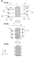
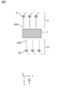
- Figure 2 is a schematic diagram showing a manufacturing method of the stator 1. Below, the top part of Figure 2 will be called the first state, the middle part of Figure 2 the second state, and the bottom part of Figure 2 the third state. First there is the first state, then the second state, and then the third state.
- the posture of the stator 1 is the same in all figures, and as shown in the lower left of Figure 2, the upper side of the figure is the positive direction of the Y axis.
- the circled G and arrows shown adjacent to the X, Y, and Z axes indicate the direction of gravitational acceleration. That is, in Figure 2, the negative Y axis direction is the direction of gravity, and the XZ plane is an approximately horizontal plane.
- the stator core 2 is arranged approximately horizontally, and L-shaped coils 400, which are conductors, are arranged on both the positive side of the Z axis and the negative side of the Z axis.
- the L-shaped coil 400 has an inclined portion 401 and a leg 402.
- the inclined portion 401 and the leg 402 are each approximately straight, and the inclined portion 401 is inclined with respect to the leg 402.
- the end of the inclined portion 401 that is not connected to the leg 402 is called the inclined end 401E, and the end of the leg 402 that is not connected to the inclined portion 401 is called the leg end 402E.
- the L-shaped coils 400 arranged on the negative side of the Z axis of the stator core 2 will be referred to as the first conductor group 41
- the L-shaped coils 400 arranged on the positive side of the Z axis of the stator core 2 will be referred to as the second conductor group 42.
- the first conductor group 41 and the second conductor group 42 are distinguished by solid and dashed lines.
- the first conductor group 41 is held by a first jig 81.
- the first jig 81 holds the legs 402 of each L-shaped coil 400 belonging to the first conductor group 41.
- the second conductor group 42 is held by a second jig 82.
- the second jig 82 holds the legs 402 of each L-shaped coil 400 belonging to the second conductor group 42.
- the configurations of the first jig 81 and the second jig 82 will be described later.
- the first conductor group 41 is moved in the positive direction of the Z axis using the first jig 81 while maintaining its cylindrical shape
- the second conductor group 42 is moved in the negative direction of the Z axis using the second jig 82 while maintaining its cylindrical shape.
- the legs 402 of the first conductor group 41 and the second conductor group 42 are inserted into the slots 3.
- the first conductor group 41 and the second conductor group 42 are inserted alternately into adjacent slots 3.
- first conductor group 41 and the second conductor group 42 are further moved and are connected to each other outside the slot 3 as shown in the lower part of Figure 2.
- the connection between the first conductor group 41 and the second conductor group 42 is described in detail as follows. That is, the leg end 402E of the first conductor group 41 is connected to the inclined end 401E of the second conductor group 42. Also, the leg end 402E of the second conductor group 42 is connected to the inclined end 401E of the first conductor group 41.
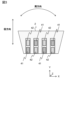
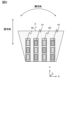
- FIG. 3 is a diagram showing the L-shaped coils 400 in the slots 3.
- FIG. 3 shows only four of the many slots 3 provided in the stator core 2. In FIG. 3, different hatching is used to distinguish between the first conductor group 41 and the second conductor group 42.
- two L-shaped coils 400 are inserted into one slot 3
- one L-shaped coil 400 from the first conductor group 41 and one L-shaped coil 400 from the second conductor group 42 are inserted into each slot 3.
- each L-shaped coil 400 advances in the radial direction of the slot 3 without other L-shaped coils 400 present until halfway through the thickness direction of the stator core 2, and from halfway through the thickness direction, the other L-shaped coils 400 act as guides to advance. Therefore, even after the first jig 81 and the second jig 82 are removed in the second state shown in the middle of Figure 2, the other adjacent L-shaped coils 400 act as guides, improving the positional accuracy of the coils.
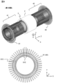
- FIG. 4 shows the first state.
- the upper part of FIG. 4 shows a perspective view of the stator 1, and the lower part of FIG. 4 shows a front view of the first jig 81.
- FIG. 4 shows the stator 1 from the same perspective as FIG. 1, with the first conductor group 41 and the second conductor group 42 arranged on either side of the stator core 2.
- the first jig 81 is arranged so as to surround the outside of the first conductor group 41 near the end on the negative side of the Z axis.
- the second jig 82 is arranged so as to surround the outside of the second conductor group 42 near the end on the positive side of the Z axis.
- the first jig 81 and the second jig 82 have the same configuration, so the configuration of the first jig 81 will be described below as a representative.
- the first jig 81 has holding holes 810 for holding the first conductor group 41. There are two rows of holding holes 810, an inner one and an outer one, similar to the L-shaped coil 400 that constitutes the first conductor group 41.
- the first conductor group 41 is a collection of holding elements 81E.
- the first jig 81 is held by a jig holder (not shown).
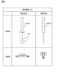
- FIG. 5 is a diagram showing the retaining element 81E.
- FIG. 5 shows the front and top views of the retaining element 81E, and further shows the retained and released states.
- the first conductor group 41 shown in the lower part of FIG. 4 is a front view of the retained state.
- the retaining element 81E forms a retaining hole 810 together with other adjacent retaining elements 81E.
- the retaining element 81E can be switched between the retained state and the released state by rotating the rotating part 81ER. In the released state, the position of the retaining element 81E changes, so that the retaining hole 810 is no longer formed, and the L-shaped coil 400 is released.
- FIG. 6 is a diagram showing the second state.
- the upper part of FIG. 6 shows a perspective view of the stator 1, and the lower part of FIG. 6 shows a front view of the first jig 81.
- FIG. 6 corresponds to FIG. 4.
- the first conductor group 41 and the second conductor group 42 overlap in the XY plane.
- the first jig 81 and the second jig 82 do not hold the first conductor group 41 and the second conductor group 42, respectively.
- the holding element 81E of the first jig 81 is in a released state.
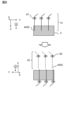
- FIG. 8 is a diagram showing a second comparative manufacturing method of the stator 1.
- the posture of the stator core 2 is changed so that the L-shaped coil 400 is inserted into the stator core 2 in the direction of gravity. That is, the first conductor group 41 is inserted in the same manner as in the first comparative manufacturing method, but when the insertion of the first conductor group 41 is completed, the stator core 2 is rotated half a turn around the Y axis together with the inserted first conductor group 41. This allows not only the first conductor group 41 but also the second conductor group 42 to be inserted into the stator core 2 in the direction of gravity.
- the stator 1 includes an annular stator core 2 with a virtual axis as its axis, a plurality of slots 3 provided in the stator core 2, and an L-shaped coil 400 arranged in line with each of the slots 3.
- the manufacturing method of the stator 1 includes a step of inserting the L-shaped coil 400 into the slot 3 of the stator core 2 with the virtual axis being substantially horizontal. Therefore, the stator 1 can be manufactured easily and with high accuracy.
- the L-shaped coil 400 can be inserted into the stator core 2 with the virtual axis being vertical.
- both the first comparative manufacturing method and the second comparative manufacturing method are inferior in accuracy to the method of the present embodiment.
- the L-shaped coil 400 has a leg 402 and an inclined portion 401 inclined relative to the leg 402.
- the manufacturing method of the stator 1 includes a first state shown in FIG. 2 in which a first conductor group, which is a plurality of conductors, has an inclined portion on one side, the legs are approximately horizontal, and each of the legs is arranged in a ring shape by a first jig, and a second conductor group, which is a plurality of conductors, has an inclined portion on the other side, the legs are approximately horizontal, and each of the legs is arranged in a ring shape by a second jig.
- the leg 402 of the first conductor group 41 is inserted into the slot 3 from the negative side to the positive side of the Z axis. Also, the leg 402 of the second conductor group 42 is inserted into the slot 3 from the positive side to the negative side of the Z axis. Therefore, the stator 1 can be manufactured using the L-shaped L-shaped coil 400, and manufacturing costs can be reduced and accuracy can be improved.
- Each leg end 402E of the first conductor group 41 is coupled to each inclined end 401E of the second conductor group 42, and each inclined end 401E of the first conductor group 41 is coupled to each leg end 402E of the second conductor group 42.
- FIG. 9 is a diagram showing the slot 3 in the first modified example.
- three L-shaped coils 400 are inserted into one slot 3.
- insertion can be performed smoothly after removing the jig as shown in FIG. 2.
- the tip of the L-shaped coil 400 can move inside the slot 3 using the other L-shaped coils 400 as a guide.
- Stator 2 Stator core 3: Slot 4: Stator conductor 41: First conductor group 42: Second conductor group 81: First jig 81E: Holding element 81ER: Rotating portion 82: Second jig 400: L-shaped coil (conductor) 401 : Inclined part 401E : Inclined end part 402 : Leg part 402E : Leg end part 810 : Holding hole
Landscapes
- Engineering & Computer Science (AREA)
- Manufacturing & Machinery (AREA)
- Power Engineering (AREA)
- Manufacture Of Motors, Generators (AREA)
Abstract
固定子の製造方法は、仮想的な軸である仮想軸を軸とする環状の固定子コアと、前記固定子コアに設けられた複数のスロットと、前記スロットの各々に並んで配置される導体と、を備える固定子の製造方法であって、前記仮想軸を略水平とした前記固定子コアの前記スロットに、前記導体を挿入する。
Description
本発明は、固定子の製造方法に関する。
回転電機を構成する固定子は、様々な製造方法が考案されている。特許文献1には帯状の平板およびリング状の帯板のうちいずれかであり、表裏両面を形成している主壁部を有し、この主壁部に加えて、この主壁部の一方の縁の多数箇所から所定間隔を空けて歯列状に突出し、互いの間に凹部状のスリットを形成している突出部と、この主壁部の表裏両面のうち一方から所定間隔を空けて突出し、この主壁部の延在方向に対して所定角度だけ傾いて延在しており、互いの間に一方のガイド溝を形成している多数の第一仕切突条と、この主壁部の表裏両面のうち他方から所定間隔を空けて突出し、この主壁部の延在方向に対してこの第一仕切突条とは逆方向に所定角度だけ傾いて延在しており、互いの間に他方のガイド溝を形成している多数の第二仕切突条と、の三者のうち少なくとも一つをさらに有することを特徴とする、絶縁性のコイル端部スペーサが開示されている。
特許文献1に記載されている発明では、固定子の製造方法に改善の余地がある。
本発明の第1の態様による固定子の製造方法は、前記固定子は、仮想的な軸である仮想軸を軸とする環状の固定子コアと、前記固定子コアに設けられた複数のスロットと、前記スロットの各々に並んで配置される導体と、を備える固定子の製造方法であって、前記仮想軸を略水平とした前記固定子コアの前記スロットに、前記導体を挿入する。
本発明によれば、簡易に高精度な固定子1を製造できる。
―実施の形態―
以下、図1~図8を参照して、固定子の製造方法の実施の形態を説明する。
以下、図1~図8を参照して、固定子の製造方法の実施の形態を説明する。
図1は、固定子1の外観図である。本実施の形態では、図面間の相関を明示するために相互に直交するXYZ軸を併記する。固定子1は、固定子コア2と、固定子コア2に設けられた複数のスロット3と、スロット3の各々に配置される固定子導体4と、を備える。固定子導体4は、後述するL字コイル400を多数組み合わせて構成される。L字コイル400は、「導体」とも呼ばれる。固定子コア2は略円筒の形状を有し、この略円筒はZ軸に平行な軸(以下、「仮想軸」と呼ぶ)を有する。それぞれのスロット3は、固定子コア2の内部に形成された、Z軸に平行な溝である。スロット3は仮想軸を中心とする円の円周上に等間隔に形成される。
固定子導体4は、固定子コア2の内部ではスロット3に沿ってZ軸に平行に配され、固定子コア2の外部の一部ではZ軸に平行ではない領域もある。なお図1に示す固定子導体4は、仮想軸を中心とする直径が異なる2つの円の円周上に配されており、いわば二重の円を形成している。しかしこの円の重なりの数は特に制限がなく、重なりがない一重の円でもよいし、3以上の重なりがあってもよい。固定子導体4は、第1導体群41および第2導体群42から構成される。
図2は、固定子1の製造方法を示す概略図である。以下では図2上段を第1状態、図2の中段を第2状態、図2の下段を第3状態と呼ぶ。まず第1状態があり、次に第2状態となる、さらに次に第3状態となる。いずれの図でも固定子1の姿勢は同一であり、図2の左下に示すように図示上側がY軸プラス方向である。またXYZ軸に隣接して示す丸囲みのGおよび矢印は重力加速度の方向を示している。すなわち図2ではY軸マイナス方向が重力方向、XZ平面は略水平面である。
まず図2の上段に示すように、固定子コア2が略水平に配置され、Z軸のプラス側およびZ軸のマイナス側のそれぞれに導体であるL字コイル400が配される。L字コイル400は、傾斜部401および脚部402を備える。傾斜部401および脚部402のそれぞれは略直線であり、傾斜部401は脚部402に対して傾斜している。傾斜部401における脚部402と接続されていない側の端部を傾斜端部401Eと呼び、脚部402における傾斜部401と接続されていない側の端部を脚端部402Eと呼ぶ。
また以下では、便宜的に固定子コア2のZ軸マイナス側に配されるL字コイル400を第1導体群41と呼び、固定子コア2のZ軸プラス側に配されるL字コイル400を第2導体群42と呼ぶ。図2では第1導体群41と第2導体群42とを識別するために、実線と破線で書き分けている。
第1導体群41は、第1治具81により保持される。第1治具81は、第1導体群41に属するそれぞれのL字コイル400の脚部402を保持する。第2導体群42は、第2治具82により保持される。第2治具82は、第2導体群42に属するそれぞれのL字コイル400の脚部402を保持する。第1治具81および第2治具82の構成は後述する。
第1治具81を用いて第1導体群41を円筒の形状に保ちながらZ軸プラス方向に移動させ、第2治具82を用いて第2導体群42を円筒の形状に保ちながらZ軸マイナス方向に移動させる。第1導体群41および第2導体群42の脚部402をスロット3に挿入される。第1導体群41および第2導体群42は、隣接するスロット3に交互に挿入される。
図2の中段に示す第2状態では、Z軸方向において、換言するとXY平面内で第1導体群41および第2導体群42に重なりが生じており、第1治具81および第2治具82が外される。換言すると、図2の中段に示すように、第1導体群41および第2導体群42の重なりである距離Lがゼロより大きくなると第1治具81および第2治具82が外される。
その後、第1導体群41および第2導体群42がさらに移動され、図2の下段に示すようにスロット3の外部で相互に接続される。第1導体群41および第2導体群42の接続を詳述すると次のとおりである。すなわち、第1導体群41の脚端部402Eと第2導体群42の傾斜端部401Eとが接続される。また、第2導体群42の脚端部402Eと第1導体群41の傾斜端部401Eとが接続される。
図3は、スロット3のL字コイル400を示す図である。図3は固定子コア2に設けられた多数のスロット3のうち、4つのみを示している。図3では、第1導体群41と第2導体群42とを区別するためにハッチングを使い分けている。本実施の形態では1つのスロット3に2つのL字コイル400が挿入され、いずれのスロット3にも第1導体群41のL字コイル400と第2導体群42のL字コイル400が1つずつ挿入される。
前述のように、第1導体群41はZ軸マイナス側からプラス側に向かって挿入され、第2導体群42はZ軸プラス側からマイナス側に向かって挿入される。そのためそれぞれのL字コイル400は、固定子コア2の厚み方向の半分まではスロット3の径方向に他のL字コイル400が存在しない状態で進行し、厚み方向の半分以降は他のL字コイル400がガイドとなって進行する。したがって図2の中段に示した第2状態において第1治具81および第2治具82を外した後も、隣接する他のL字コイル400がガイドとなり、コイルの位置精度が向上する。
図4は、第1状態を示す図である。図4の上部には固定子1の斜視図を示し、図4の下部には第1治具81の正面図を示している。図4は図1と同じ視点から固定子1を見ており、固定子コア2の両側に第1導体群41および第2導体群42が配されている。第1導体群41におけるZ軸マイナス側の端部近くで外側を囲むように配されているのが第1治具81である。第2導体群42におけるZ軸プラス側の端部近くで外側を囲むように配されているのが第2治具82である。第1治具81および第2治具82の構成は同一なので、以下では代表して第1治具81の構成を説明する。
第1治具81は、第1導体群41を保持するための保持穴810を備える。保持穴810は、第1導体群41を構成するL字コイル400と同様に、内側と外側の2列が存在する。第1導体群41は、保持要素81Eの集合体である。なお第1治具81は、不図示の治具保持具により保持される。
図5は、保持要素81Eを示す図である。図5は、保持要素81Eの正面視および上面視を示し、さらに保持状態と解放状態を示している。図4の下部に示した第1導体群41は保持状態の正面視であった。保持要素81Eは、隣接する他の保持要素81Eとともに保持穴810を形成する。保持要素81Eは、回転部81ERを回転させることで保持状態と解放状態とを切り替えられる。解放状態では保持要素81Eの姿勢が変化したことで保持穴810が形成されなくなり、L字コイル400が解放される。
図6は、第2状態を示す図である。図6の上部には固定子1の斜視図を示し、図6の下部には第1治具81の正面図を示している。図6は図4に対応する。図6では、XY平面内で第1導体群41および第2導体群42に重なりが生じている。また、第2状態では第1治具81および第2治具82のそれぞれは、第1導体群41および第2導体群42を保持しない。図6の下段に示すように、第1治具81の保持要素81Eは解放状態となっている。
図7は固定子1の第1比較例製造方法を示す図である。図7を図2と比較すると、固定子1の姿勢が90度回転しているが、重力方向は図示下側から変化がない。第1比較例製造方法では重力に平行なZ軸に沿って、第1導体群41および第2導体群42を移動させる。第1導体群41は重力方向への移動であり、第1治具81が上部を保持しているので脚端部402Eの位置調整に特段の困難さはない。しかし第2導体群42は第2治具82によりZ軸方向の下部側を保持しており、鉛直上向きに移動させるので脚端部402Eの位置精度が悪化する。したがって、図2に示した本実施の形態における製造方法は、第1比較例製造方法よりも精度の点で優れている。
図8は固定子1の第2比較例製造方法を示す図である。第2比較例製造方法では、L字コイル400の固定子コア2への挿入が重力方向となるように、固定子コア2の姿勢を変更する。すなわち、第1導体群41の挿入は第1比較例製造方法と同様に行うが、第1導体群41の挿入が完了すると、固定子コア2を挿入された第1導体群41とともにY軸周りに半回転させる。これにより第1導体群41だけでなく第2導体群42も固定子コア2への挿入を重力方向にできる。ただし、固定子コア2をY軸周りに回転させる際に位置のずれが避けられない。また固定子コア2をY軸周りに回転させる機構や、固定子コア2を回転させるための空間が必要となる問題もある。したがって、図2に示した本実施の形態における製造方法は、第2比較例製造方法よりも精度の点、必要設備の少なさ、および専有面積の少なさで優れている。
上述した実施の形態によれば、次の作用効果が得られる。
(1)固定子1は、仮想的な軸である仮想軸を軸とする環状の固定子コア2と、固定子コア2に設けられた複数のスロット3と、スロット3の各々に並んで配置されるL字コイル400と、を備える。固定子1の製造方法は、仮想軸を略水平とした固定子コア2のスロット3に、L字コイル400を挿入する工程を含む。そのため、簡易に高精度な固定子1を製造できる。たとえば第1比較例製造方法や第2比較例製造方法のように、仮想軸を垂直とした固定子コア2にL字コイル400を挿入することもできる。しかし第1比較例製造方法および第2比較例製造方法のいずれも、本実施の形態の手法に比べて精度が劣る。
(1)固定子1は、仮想的な軸である仮想軸を軸とする環状の固定子コア2と、固定子コア2に設けられた複数のスロット3と、スロット3の各々に並んで配置されるL字コイル400と、を備える。固定子1の製造方法は、仮想軸を略水平とした固定子コア2のスロット3に、L字コイル400を挿入する工程を含む。そのため、簡易に高精度な固定子1を製造できる。たとえば第1比較例製造方法や第2比較例製造方法のように、仮想軸を垂直とした固定子コア2にL字コイル400を挿入することもできる。しかし第1比較例製造方法および第2比較例製造方法のいずれも、本実施の形態の手法に比べて精度が劣る。
(2)L字コイル400は、脚部402と、脚部402に対し傾斜する傾斜部401とを備える。固定子1の製造方法は、複数の導体である第1導体群を、一方側を傾斜部とし、脚部を略水平にして、脚部の各々を第1治具で環状に配置し、複数の導体である第2導体群を、他方側を傾斜部とし、脚部を略水平にして、脚部の各々を第2治具で環状に配置する図2に示した第1状態を含む。第1状態において、スロット3に、Z軸マイナス側からプラス側に向かって、第1導体群41の脚部402を挿入する。また、スロット3に、Z軸プラス側からマイナス側に向かって第2導体群42の脚部402を挿入する。そのため、L字状のL字コイル400を用いて固定子1を製造でき、製造コストの低減および精度の向上が達成できる。
(3)第1導体群41の脚部402と第2導体群42の脚部402とがZ軸方向に重なった状態で、第1治具81および第2治具82を導体から外し、第1導体群41を他方側に向かってさらに挿入し、第2導体群42を一方側に向かってさらに挿入する。そのため、第1治具81および第2治具82を外した後も隣接する他のL字コイル400がガイドとなり、コイルの位置精度が向上する。
(4)第1導体群41の各々の脚端部402Eを、第2導体群42の各々の傾斜端部401Eと結合し、第1導体群41の各々の傾斜端部401Eを第2導体群42の各々の脚端部402Eと結合する。
(変形例1)
上述した実施の形態ではそれぞれのスロット3に2つのL字コイル400が挿入されたが、スロット3に挿入されるL字コイル400は1でもよいし3以上でもよい。スロット3に挿入されるL字コイル400が3以上の場合には、第1導体群41に属するL字コイル400と第2導体群42に属するL字コイル400とが径方向に交互に配置されればよい。
上述した実施の形態ではそれぞれのスロット3に2つのL字コイル400が挿入されたが、スロット3に挿入されるL字コイル400は1でもよいし3以上でもよい。スロット3に挿入されるL字コイル400が3以上の場合には、第1導体群41に属するL字コイル400と第2導体群42に属するL字コイル400とが径方向に交互に配置されればよい。
図9は変形例1におけるスロット3を示す図である。図9に示す例では1つのスロット3に3つのL字コイル400が挿入される例を示している。このように、1つのスロットに挿入されるL字コイル400の数が変化しても、図2に示したように治具取り外し後の挿入がスムーズに行える。具体的には、第1導体群41の脚部402と第2導体群42の脚部402とがZ軸方向に重なった状態で第1治具81および第2治具82を導体から外すと、スロット3の内部ではL字コイル400の先端は他のL字コイル400をガイドとして移動できる。
本発明は実施の形態および変形例の内容に限定されるものではない。本発明の技術的思想の範囲内で考えられるその他の態様も本発明の範囲内に含まれる。
1 :固定子
2 :固定子コア
3 :スロット
4 :固定子導体
41 :第1導体群
42 :第2導体群
81 :第1治具
81E :保持要素
81ER :回転部
82 :第2治具
400 :L字コイル(導体)
401 :傾斜部
401E :傾斜端部
402 :脚部
402E :脚端部
810 :保持穴
2 :固定子コア
3 :スロット
4 :固定子導体
41 :第1導体群
42 :第2導体群
81 :第1治具
81E :保持要素
81ER :回転部
82 :第2治具
400 :L字コイル(導体)
401 :傾斜部
401E :傾斜端部
402 :脚部
402E :脚端部
810 :保持穴
Claims (4)
- 仮想的な軸である仮想軸を軸とする環状の固定子コアと、
前記固定子コアに設けられた複数のスロットと、
前記スロットの各々に並んで配置される導体と、を備える固定子の製造方法であって、
前記仮想軸を略水平とした前記固定子コアの前記スロットに、前記導体を挿入する、固定子の製造方法。 - 請求項1に記載の製造方法であって、
前記導体は、脚部と、前記脚部に対し傾斜する傾斜部とを備え、
複数の前記導体である第1導体群を、一方側を前記傾斜部とし、前記脚部を略水平にして、前記脚部の各々を第1治具で環状に配置し、複数の前記導体である第2導体群を、他方側を前記傾斜部とし、前記脚部を略水平にして、前記脚部の各々を第2治具で環状に配置し、
前記スロットに、前記一方側から、前記第1導体群の脚部を挿入し、前記スロットに、前記他方側から、前記第2導体群の脚部を挿入する、固定子の製造方法。 - 請求項2に記載の固定子の製造方法であって、
前記スロットの各々には、前記第1導体群に含まれる前記導体、および前記第2導体群に含まれる前記導体がそれぞれ挿入され、
前記第1導体群の前記脚部と前記第2導体群の前記脚部とが前記仮想軸の方向に重なった状態で、前記第1治具および前記第2治具を前記導体から外し、
前記第1導体群を前記他方側に向かってさらに挿入し、前記第2導体群を前記一方側に向かってさらに挿入する、固定子の製造方法。 - 請求項2に記載の固定子の製造方法であって、
前記第1導体群の各々の前記脚部の端を、記第2導体群の各々の前記傾斜部の端と結合し、前記第1導体群の各々の前記傾斜部の端を前記第2導体群の各々の前記脚部の端と結合する、固定子の製造方法。
Priority Applications (3)
| Application Number | Priority Date | Filing Date | Title |
|---|---|---|---|
| CN202380099403.3A CN121336347A (zh) | 2023-07-06 | 2023-07-06 | 定子的制造方法 |
| JP2025530951A JPWO2025009174A1 (ja) | 2023-07-06 | 2023-07-06 | |
| PCT/JP2023/025191 WO2025009174A1 (ja) | 2023-07-06 | 2023-07-06 | 固定子の製造方法 |
Applications Claiming Priority (1)
| Application Number | Priority Date | Filing Date | Title |
|---|---|---|---|
| PCT/JP2023/025191 WO2025009174A1 (ja) | 2023-07-06 | 2023-07-06 | 固定子の製造方法 |
Publications (1)
| Publication Number | Publication Date |
|---|---|
| WO2025009174A1 true WO2025009174A1 (ja) | 2025-01-09 |
Family
ID=94171434
Family Applications (1)
| Application Number | Title | Priority Date | Filing Date |
|---|---|---|---|
| PCT/JP2023/025191 Ceased WO2025009174A1 (ja) | 2023-07-06 | 2023-07-06 | 固定子の製造方法 |
Country Status (3)
| Country | Link |
|---|---|
| JP (1) | JPWO2025009174A1 (ja) |
| CN (1) | CN121336347A (ja) |
| WO (1) | WO2025009174A1 (ja) |
Citations (3)
| Publication number | Priority date | Publication date | Assignee | Title |
|---|---|---|---|---|
| JPS5638969A (en) * | 1979-09-03 | 1981-04-14 | Toshiba Corp | Device for inserting and forming coil |
| JP2019161865A (ja) * | 2018-03-13 | 2019-09-19 | 本田技研工業株式会社 | 回転電機用ステータの製造装置、及び回転電機用ステータの製造方法 |
| JP2022134855A (ja) * | 2021-03-04 | 2022-09-15 | 本田技研工業株式会社 | コイル装着装置及びコイル装着方法 |
-
2023
- 2023-07-06 JP JP2025530951A patent/JPWO2025009174A1/ja active Pending
- 2023-07-06 WO PCT/JP2023/025191 patent/WO2025009174A1/ja not_active Ceased
- 2023-07-06 CN CN202380099403.3A patent/CN121336347A/zh active Pending
Patent Citations (3)
| Publication number | Priority date | Publication date | Assignee | Title |
|---|---|---|---|---|
| JPS5638969A (en) * | 1979-09-03 | 1981-04-14 | Toshiba Corp | Device for inserting and forming coil |
| JP2019161865A (ja) * | 2018-03-13 | 2019-09-19 | 本田技研工業株式会社 | 回転電機用ステータの製造装置、及び回転電機用ステータの製造方法 |
| JP2022134855A (ja) * | 2021-03-04 | 2022-09-15 | 本田技研工業株式会社 | コイル装着装置及びコイル装着方法 |
Also Published As
| Publication number | Publication date |
|---|---|
| CN121336347A (zh) | 2026-01-13 |
| JPWO2025009174A1 (ja) | 2025-01-09 |
Similar Documents
| Publication | Publication Date | Title |
|---|---|---|
| CN103178665B (zh) | 定子的制造方法、定子的制造装置以及定子 | |
| KR102905676B1 (ko) | 확장과 비틀림을 위한 장치 및 방법 | |
| CN104426304B (zh) | 旋转电机的制造方法 | |
| CN112262520B (zh) | 使从电机的定子或转子的一侧突出的导体变形的装置和方法 | |
| JP6570100B1 (ja) | コイル形成装置及びコイル形成方法 | |
| US20190006922A1 (en) | Devices and methods for positioning copper rods | |
| TWI722253B (zh) | 線圈變形裝置及定子製造裝置以及定子之製造方法 | |
| JP2016163424A (ja) | ステータの製造方法及びその製造装置 | |
| KR102660163B1 (ko) | 전기 기계를 위한 연속 바 와인딩 제작 방법 | |
| JP2020182339A (ja) | 整列装置および整列コイルの製造方法 | |
| US20180331605A1 (en) | Coil forming device and coil forming method | |
| JP7373891B2 (ja) | コイル挿入装置及びコイル挿入方法 | |
| US20210111612A1 (en) | Method And Device For Twisting A Winding Head Of A Stator And Stator For An Electrical Machine | |
| US8230578B2 (en) | Method for producing a winding of an electrical machine | |
| CN108258856A (zh) | 引出线定位装置、定子的制造方法、马达的制造方法和马达 | |
| WO2009125706A1 (ja) | インナーロータ型回転電機の分割コア型ステータの組み立て方法 | |
| JP2023121475A (ja) | ステータの製造方法 | |
| JP2018074688A (ja) | ステータ連結装置、ステータの製造方法、モータ | |
| JP2017046373A (ja) | コイルのスロットへの挿入方法、及びコイル挿入装置 | |
| JP2023145238A (ja) | ステータの製造方法及びステータの製造装置 | |
| CN121336347A (zh) | 定子的制造方法 | |
| JP4443286B2 (ja) | 回転電動機の固定子、回転電動機のコイル装着方法、コイル巻線機 | |
| JP2003125564A (ja) | 回転電機のコイル製造装置 | |
| JP2019161865A (ja) | 回転電機用ステータの製造装置、及び回転電機用ステータの製造方法 | |
| CN105164901A (zh) | 旋转电机用定子的制造方法 |
Legal Events
| Date | Code | Title | Description |
|---|---|---|---|
| 121 | Ep: the epo has been informed by wipo that ep was designated in this application |
Ref document number: 23944421 Country of ref document: EP Kind code of ref document: A1 |
|
| ENP | Entry into the national phase |
Ref document number: 2025530951 Country of ref document: JP Kind code of ref document: A |
|
| NENP | Non-entry into the national phase |
Ref country code: DE |
|
| 122 | Ep: pct application non-entry in european phase |
Ref document number: 23944421 Country of ref document: EP Kind code of ref document: A1 |