WO2025009113A1 - エレベーター装置 - Google Patents
エレベーター装置 Download PDFInfo
- Publication number
- WO2025009113A1 WO2025009113A1 PCT/JP2023/024975 JP2023024975W WO2025009113A1 WO 2025009113 A1 WO2025009113 A1 WO 2025009113A1 JP 2023024975 W JP2023024975 W JP 2023024975W WO 2025009113 A1 WO2025009113 A1 WO 2025009113A1
- Authority
- WO
- WIPO (PCT)
- Prior art keywords
- ratchet
- pawl
- flyweight
- biasing member
- emergency stop
- Prior art date
- Legal status (The legal status is an assumption and is not a legal conclusion. Google has not performed a legal analysis and makes no representation as to the accuracy of the status listed.)
- Ceased
Links
Images





Classifications
-
- B—PERFORMING OPERATIONS; TRANSPORTING
- B66—HOISTING; LIFTING; HAULING
- B66B—ELEVATORS; ESCALATORS OR MOVING WALKWAYS
- B66B5/00—Applications of checking, fault-correcting, or safety devices in elevators
- B66B5/02—Applications of checking, fault-correcting, or safety devices in elevators responsive to abnormal operating conditions
- B66B5/04—Applications of checking, fault-correcting, or safety devices in elevators responsive to abnormal operating conditions for detecting excessive speed
Definitions
- This disclosure relates to elevator devices.
- Patent Document 1 discloses an elevator governor.
- an inspection lever is provided on a base that can be displaced between a standby position and an inspection position where the flyweight is rotated to engage the latch with the ratchet, and the inspection lever is remotely operated from the landing side via an inspection wire to displace it.
- the pawl is biased in a direction away from the ratchet. This means that when the car rises after the emergency stop device is activated, the pawl automatically returns to its normal operating position.
- Emergency stop tests may be required during qualification tests, pre-completion inspections, and regular inspections. If the emergency stop device is activated during an emergency stop test, the counterweight that jumps due to inertia may fall and the resulting swing back motion may cause the claw to separate from the ratchet, causing the governor to reset. If the governor resets, there is a problem that the car may once again free fall to an abnormal speed.
- the purpose of this disclosure is to provide an elevator device that can prevent the governor from returning to its original position due to swinging back when the emergency stop device is activated.
- the elevator device is an elevator device equipped with a speed governor, which includes a pulley, a flyweight that displaces according to the rotational speed of the pulley, a ratchet for activating an emergency stop device, a pawl that displaces together with the flyweight and can engage with the ratchet, and a biasing member that biases the pawl when the pawl engages with the ratchet so that the pawl does not come off the ratchet.
- a speed governor which includes a pulley, a flyweight that displaces according to the rotational speed of the pulley, a ratchet for activating an emergency stop device, a pawl that displaces together with the flyweight and can engage with the ratchet, and a biasing member that biases the pawl when the pawl engages with the ratchet so that the pawl does not come off the ratchet.
- This disclosure makes it possible to provide an elevator device that can prevent the governor from returning to its original position due to backswinging when the emergency stop device is activated.
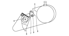
- FIG. 2 is a diagram showing a speed governor provided in the elevator apparatus according to the first embodiment.
- FIG. 13 shows the initial positions of the flyweights and the claws.
- FIG. 3 is a diagram showing a state in which the speed of the car is increased compared to the state in FIG. 2 .
- 13 is a diagram showing the state at the moment when the pawl engages with the ratchet, the rope catch catches the governor rope, and the emergency stop device is activated.
- FIG. 13 is a diagram showing the state when the car is stopped by the safety device and the rotation of the pulley is stopped.
- FIG. FIG. 13 is a diagram showing the state when the car rises slightly due to backswinging after the safety device is activated.
- FIG. 13 is a diagram showing the state when the car is lowered.
- Fig. 1 is a diagram showing a speed governor provided in an elevator system according to embodiment 1.
- the speed governor 1 shown in Fig. 1 is a device for forcibly stopping the movement of an elevator car (not shown) when the moving speed of the car exceeds a specific speed.
- the governor 1 includes a pulley 2.
- a governor rope (not shown) is wound around the pulley 2.
- the governor rope is connected to the car.
- the governor rope moves with the movement of the car, causing the pulley 2 to rotate.
- the pulley 2 rotates clockwise in FIG. 1, and when the car descends, the pulley 2 rotates counterclockwise in FIG. 1.
- the flyweight 3 is attached to the pulley 2.
- the flyweight 3 is displaced according to the rotational speed of the pulley 2.
- the flyweight 3 is rotatable about a first rotation axis 4 relative to the pulley 2.
- the flyweight 3 is displaced by the centrifugal force of the rotation of the pulley 2.
- a pair of flyweights 3 are provided so as to be point symmetrical with respect to the center of the pulley 2. Only one of the flyweights 3 is shown in FIG. 1.
- the governor 1 is equipped with a ratchet 5 for activating the emergency stop device.
- the ratchet 5 is a ratchet wheel arranged concentrically with the pulley 2.
- the governor 1 has a pawl 6.
- the pawl 6 is displaceable together with the flyweight 3 and can engage with the ratchet 5.
- the pawl 6 is rotatable about the first rotating shaft 4 relative to the flyweight 3.
- the flyweight 3 is displaced by centrifugal force, the pawl 6 is displaced in an operating direction approaching the ratchet 5.
- the operating direction is a counterclockwise direction about the first rotating shaft 4.
- the ratchet 5 engages with the pawl 6.
- the ratchet 5 rotates and the rope catch (not shown) catches the governor rope, activating the car's emergency stop device (not shown), forcing the car to stop.
- the pawl 6 is biased by a spring (not shown) in a direction away from the ratchet 5, i.e., in the return direction.
- the return direction is a clockwise direction around the first rotating shaft 4.
- the emergency stop device is normally activated when the main rope suspending the cage and counterweight breaks. In response to this, there are cases where an operation test of the emergency stop device is required during certification testing, pre-completion inspection, regular inspection, etc. In such cases, the emergency stop device is activated in a suspended state where the main rope is not broken. At that time, if the emergency stop device is activated and the cage stops suddenly, the counterweight jumps due to inertia, and when the speed becomes 0, it begins to free fall by the amount of the jump. At this time, if the hoist brake is not activated, the cage rises slightly due to the energy of the counterweight's free fall. In this disclosure, this phenomenon is referred to as "swing back." If the governor 1 is reset due to the rise of the cage during this swing back, there is a problem that the cage will again free fall to an abnormal speed after the emergency stop device is activated.
- a biasing member 7 is provided on the flyweight 3 to bias the pawl 6 so that the pawl 6 does not come off the ratchet 5 when the pawl 6 engages with the ratchet 5.
- the biasing member 7 in this embodiment is a leaf spring.
- the biasing member 7 in this disclosure is not limited to a leaf spring, and may be, for example, a coil spring.
- Figure 2 shows the initial positions of the flyweight 3 and the claw 6.
- Figure 2 shows the state when the speed of the cage is below the rated speed.
- the biasing member 7 is not biasing the claw 6.
- the claw 6 is not receiving force from the biasing member 7 in either the operating direction or the return direction.
- a bolt 9 provided at the rear end of the claw 6 abuts against a recess 8 formed in the flyweight 3.
- Figure 3 shows a state where the cage speed has increased from the state shown in Figure 2.
- Figure 3 shows the state when the cage descends at an abnormal speed higher than the rated speed.
- the flyweight 3 and the pawl 6 rotate together in the operating direction around the first rotating shaft 4.
- the relative positional relationship between the pawl 6 and the biasing member 7 is the same as in Figure 2.
- the biasing member 7 does not bias the pawl 6 until the pawl 6 engages with the ratchet 5, so the biasing member 7 can be prevented from affecting the original function of the governor 1.
- Figure 4 shows the state at the moment when the pawl 6 engages with the ratchet 5, the rope catch catches the governor rope, and the emergency stop device is activated.
- the relative positional relationship between the pawl 6 and the biasing member 7 is the same as in Figure 2.
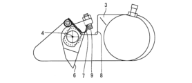
- Figure 5 shows the state when the car is stopped by the emergency stop device and the rotation of the pulley 2 stops.
- the flyweight 3 returns to its original position due to the force of the spring (not shown), but since the pawl 6 is engaged with the ratchet 5, it does not return to its original position and the rotation angle of the pawl 6 is maintained.
- the biasing member 7 gets under the bolt 9 of the pawl 6, and the biasing member 7 biases the pawl 6 in the operating direction.
- the pawl 6 is rotatable relative to the flyweight 3 around the first rotating shaft 4, so that when the flyweight 3 rotates in the return direction and returns to its original position, the pawl 6 can maintain its state of engagement with the ratchet 5.
- Figure 6 shows the state when the car rises slightly due to rocking after the emergency stop device has been activated.
- the pawl 6 and ratchet 5 attempt to disengage, but the biasing member 7 contacts the bolt 9 and biases the pawl 6 in the operating direction, so the pawl 6 maintains its engagement with the ratchet 5. Therefore, the governor 1 does not return to its original position, and the emergency stop device remains activated. Furthermore, even if the car moves in the upward direction after the pawl 6 engages with the ratchet 5, the pawl 6 rides up the teeth of the ratchet 5, so the movement of the pawl 6 and ratchet 5 is not impeded.
- Figure 7 shows the state when the car is lowered.
- the pawl 6 is held in a position to engage with the ratchet 5 by the biasing member 7, so the pawl 6 engages with the ratchet 5 regardless of the speed. Therefore, even if the car is lowered, the governor 1 does not return to its original position, and the rope catch catches the governor rope, instantly activating the emergency stop device. In this way, the state in which the emergency stop device is activated is maintained.
- the relative positional relationship between the biasing member 7 and the pawl 6 is the same as in Figure 5.
- the biasing member 7 is removable from the flyweight 3.
- the biasing member 7 is a jig that is attached only when testing the emergency stop device. Under normal circumstances, the biasing member 7 is removed. This allows the governor 1 to be in an automatic resettable state under normal circumstances, and in a non-automatic resettable state during inspection.
- the biasing member 7 does not bias the pawl 6 until the pawl 6 engages with the ratchet 5 and the emergency stop device is activated, and when the pawl 6 engages with the ratchet 5 and the emergency stop device is activated, the biasing member 7 biases the pawl 6 in the activation direction so that the pawl 6 does not come off the ratchet 5.
- the emergency stop device does not activate immediately when the car descends, but rather allows normal movement (travel at the rated speed) until it is activated once.
Landscapes
- Maintenance And Inspection Apparatuses For Elevators (AREA)
Priority Applications (3)
| Application Number | Priority Date | Filing Date | Title |
|---|---|---|---|
| JP2025530898A JPWO2025009113A1 (https=) | 2023-07-05 | 2023-07-05 | |
| PCT/JP2023/024975 WO2025009113A1 (ja) | 2023-07-05 | 2023-07-05 | エレベーター装置 |
| CN202380099314.9A CN121443544A (zh) | 2023-07-05 | 2023-07-05 | 电梯装置 |
Applications Claiming Priority (1)
| Application Number | Priority Date | Filing Date | Title |
|---|---|---|---|
| PCT/JP2023/024975 WO2025009113A1 (ja) | 2023-07-05 | 2023-07-05 | エレベーター装置 |
Publications (1)
| Publication Number | Publication Date |
|---|---|
| WO2025009113A1 true WO2025009113A1 (ja) | 2025-01-09 |
Family
ID=94171259
Family Applications (1)
| Application Number | Title | Priority Date | Filing Date |
|---|---|---|---|
| PCT/JP2023/024975 Ceased WO2025009113A1 (ja) | 2023-07-05 | 2023-07-05 | エレベーター装置 |
Country Status (3)
| Country | Link |
|---|---|
| JP (1) | JPWO2025009113A1 (https=) |
| CN (1) | CN121443544A (https=) |
| WO (1) | WO2025009113A1 (https=) |
Citations (6)
| Publication number | Priority date | Publication date | Assignee | Title |
|---|---|---|---|---|
| JPH08119555A (ja) * | 1994-10-20 | 1996-05-14 | Mitsubishi Electric Corp | エレベータ用調速機 |
| JP2001106454A (ja) * | 1999-10-05 | 2001-04-17 | Mitsubishi Electric Corp | エレベータ用調速機 |
| JP2009286605A (ja) * | 2008-05-30 | 2009-12-10 | Fujitec Co Ltd | エレベータ用調速機 |
| JP2011042427A (ja) * | 2009-08-19 | 2011-03-03 | Fujitec Co Ltd | エレベータの調速機 |
| CN106586760A (zh) * | 2016-12-12 | 2017-04-26 | 快意电梯股份有限公司 | 防止无机房电梯限速器自动复位的装置 |
| WO2019224881A1 (ja) * | 2018-05-21 | 2019-11-28 | 三菱電機株式会社 | エレベータ調速機及びエレベータ装置 |
-
2023
- 2023-07-05 JP JP2025530898A patent/JPWO2025009113A1/ja active Pending
- 2023-07-05 WO PCT/JP2023/024975 patent/WO2025009113A1/ja not_active Ceased
- 2023-07-05 CN CN202380099314.9A patent/CN121443544A/zh active Pending
Patent Citations (6)
| Publication number | Priority date | Publication date | Assignee | Title |
|---|---|---|---|---|
| JPH08119555A (ja) * | 1994-10-20 | 1996-05-14 | Mitsubishi Electric Corp | エレベータ用調速機 |
| JP2001106454A (ja) * | 1999-10-05 | 2001-04-17 | Mitsubishi Electric Corp | エレベータ用調速機 |
| JP2009286605A (ja) * | 2008-05-30 | 2009-12-10 | Fujitec Co Ltd | エレベータ用調速機 |
| JP2011042427A (ja) * | 2009-08-19 | 2011-03-03 | Fujitec Co Ltd | エレベータの調速機 |
| CN106586760A (zh) * | 2016-12-12 | 2017-04-26 | 快意电梯股份有限公司 | 防止无机房电梯限速器自动复位的装置 |
| WO2019224881A1 (ja) * | 2018-05-21 | 2019-11-28 | 三菱電機株式会社 | エレベータ調速機及びエレベータ装置 |
Also Published As
| Publication number | Publication date |
|---|---|
| CN121443544A (zh) | 2026-01-30 |
| JPWO2025009113A1 (https=) | 2025-01-09 |
Similar Documents
| Publication | Publication Date | Title |
|---|---|---|
| CN107021395B (zh) | 具有自动复位的电梯超速调节器 | |
| US5653312A (en) | Elevator governor | |
| CN107673159B (zh) | 升降机的限速器 | |
| CA2973759C (en) | Safety brake for a lifting device | |
| CN101054143B (zh) | 离心致动装置 | |
| JP5312487B2 (ja) | エレベータ用安全装置 | |
| JP5428640B2 (ja) | エレベータの調速機 | |
| CN100540436C (zh) | 电梯用限速器 | |
| WO2012017549A1 (ja) | エレベータ用調速機 | |
| EP1770044B1 (en) | Speed governor of elevator | |
| JPH092756A (ja) | 双方向エレベータガバナーおよびガバナーシーブの停止方法 | |
| GB2110633A (en) | Cable drum safety device | |
| JP4423261B2 (ja) | エレベータのガバナデバイス | |
| CN112424103B (zh) | 电梯的限速器 | |
| WO2025009113A1 (ja) | エレベーター装置 | |
| US6186281B1 (en) | Remote storage and reset of elevator overspeed switch | |
| JP6517372B2 (ja) | エレベーター装置 | |
| JP2007084260A (ja) | エレベータの調速機 | |
| JPWO2010084563A1 (ja) | エレベータ用安全装置 | |
| JP5157648B2 (ja) | エレベータ用調速機 | |
| CN210558728U (zh) | 限速器 | |
| WO2010084564A1 (ja) | エレベータ用安全装置 | |
| CN119911774B (zh) | 轿架随动限速器及电梯 | |
| WO2019224881A1 (ja) | エレベータ調速機及びエレベータ装置 | |
| CN100427375C (zh) | 电梯用调速器 |
Legal Events
| Date | Code | Title | Description |
|---|---|---|---|
| 121 | Ep: the epo has been informed by wipo that ep was designated in this application |
Ref document number: 23944362 Country of ref document: EP Kind code of ref document: A1 |
|
| ENP | Entry into the national phase |
Ref document number: 2025530898 Country of ref document: JP Kind code of ref document: A |
|
| WWE | Wipo information: entry into national phase |
Ref document number: 2025530898 Country of ref document: JP |
|
| NENP | Non-entry into the national phase |
Ref country code: DE |