WO2025009111A1 - 遮熱装置 - Google Patents
遮熱装置 Download PDFInfo
- Publication number
- WO2025009111A1 WO2025009111A1 PCT/JP2023/024966 JP2023024966W WO2025009111A1 WO 2025009111 A1 WO2025009111 A1 WO 2025009111A1 JP 2023024966 W JP2023024966 W JP 2023024966W WO 2025009111 A1 WO2025009111 A1 WO 2025009111A1
- Authority
- WO
- WIPO (PCT)
- Prior art keywords
- heat shield
- unit
- exhaust pipe
- disposed
- vehicle body
- Prior art date
- Legal status (The legal status is an assumption and is not a legal conclusion. Google has not performed a legal analysis and makes no representation as to the accuracy of the status listed.)
- Ceased
Links
Images


Classifications
-
- B—PERFORMING OPERATIONS; TRANSPORTING
- B60—VEHICLES IN GENERAL
- B60K—ARRANGEMENT OR MOUNTING OF PROPULSION UNITS OR OF TRANSMISSIONS IN VEHICLES; ARRANGEMENT OR MOUNTING OF PLURAL DIVERSE PRIME-MOVERS IN VEHICLES; AUXILIARY DRIVES FOR VEHICLES; INSTRUMENTATION OR DASHBOARDS FOR VEHICLES; ARRANGEMENTS IN CONNECTION WITH COOLING, AIR INTAKE, GAS EXHAUST OR FUEL SUPPLY OF PROPULSION UNITS IN VEHICLES
- B60K1/00—Arrangement or mounting of electrical propulsion units
- B60K1/04—Arrangement or mounting of electrical propulsion units of the electric storage means for propulsion
-
- B—PERFORMING OPERATIONS; TRANSPORTING
- B60—VEHICLES IN GENERAL
- B60K—ARRANGEMENT OR MOUNTING OF PROPULSION UNITS OR OF TRANSMISSIONS IN VEHICLES; ARRANGEMENT OR MOUNTING OF PLURAL DIVERSE PRIME-MOVERS IN VEHICLES; AUXILIARY DRIVES FOR VEHICLES; INSTRUMENTATION OR DASHBOARDS FOR VEHICLES; ARRANGEMENTS IN CONNECTION WITH COOLING, AIR INTAKE, GAS EXHAUST OR FUEL SUPPLY OF PROPULSION UNITS IN VEHICLES
- B60K13/00—Arrangement in connection with combustion air intake or gas exhaust of propulsion units
Definitions
- the present invention relates to a heat shielding device used in vehicles such as automobiles, and in particular to a heat shielding device used to protect units such as drive sources and batteries from the heat of exhaust pipes.
- Patent Document 1 describes a cooling structure for a generator unit for a range extender vehicle that includes a generator engine that supplies power to the vehicle and a muffler through which exhaust gas from the generator engine flows.
- the generator engine has a cylinder case and a cooling fan that draws air into the cylinder case, and an opening is provided in the wall of the cylinder case to exhaust the air inside the cylinder case.
- the muffler has a muffler body through which exhaust gas flows, and a cover member formed of a heat shield that covers the muffler body, and a communication passage part is provided between the cover member and the cylinder case.
- the cooling structure is configured so that air taken in by the cooling fan flows through the cylinder case and the communication passage part into the cover member and is exhausted to the outside.
- each unit such as the body, engine, motor, battery, frame, and drive transmission system, is combined with cushioning materials to absorb individual vibrations.
- all of the cooling system passages are connected, so it is necessary to have a structure in which the cooling passages are divided for each unit, which creates the risk of thermal damage due to heat leakage.
- the present invention was made in consideration of the above-mentioned conventional situation, and aims to provide a heat shielding device that can protect the first and second units arranged around the exhaust pipe from heat damage caused by the exhaust pipe without being affected by the individual vibrations of each unit, in a structure in which a first unit is swingably mounted on the vehicle body, a second unit is fixed to the vehicle body, and an exhaust pipe is arranged between the first and second units.
- the heat shield device of the present invention comprises a first unit that is swingably mounted on the vehicle body, a second unit that is disposed adjacent to the first unit and fixed to the vehicle body, and an exhaust pipe that is disposed between the first unit and the second unit.
- This heat shield device comprises a first heat shield plate that is fixed to the first unit and disposed on the exhaust pipe side of the first unit, and a second heat shield plate that is fixed to the second unit and disposed on the exhaust pipe side of the second unit.
- the heat shield device is characterized in that the first heat shield plate and the second heat shield plate have extensions that protrude at different heights above the exhaust pipe and have tip portions that overlap when viewed from above the vehicle.
- the heat shield device of the present invention employs the above configuration, and in a structure in which a first unit is swingably mounted on the vehicle body, a second unit is fixed to the vehicle body, and an exhaust pipe is arranged between the first and second units, the first and second units arranged around the exhaust pipe can be protected from heat damage caused by the exhaust pipe without being affected by the individual vibrations of each unit.
- FIG. 1 is a plan view of an underside of a vehicle showing an embodiment of a heat shield device according to the present invention.
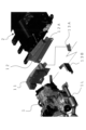
- FIG. 4 is an exploded perspective view illustrating a method for attaching the first heat shield plate and the second heat shield plate.
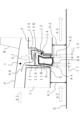
- FIG. 2 is a cross-sectional view showing a main part of the heat shield device. 4 is a cross-sectional view showing a main part of the heat shield device when the vehicle is stopped.
- the vehicle V shown in Figure 1 has a frame F and front, rear, left and right wheels W, as well as a first unit 1 that is swingably mounted on the vehicle body, a second unit 2 that is disposed adjacent to the first unit 1 and fixed to the vehicle body, an auxiliary motor 3 as another unit that is disposed to the rear of the second unit 2, and an inverter 4.
- the first unit 1 is located at the front of the vehicle body and is specifically a drive source that integrates an engine and a main motor.
- the second unit 2 is located at the rear of the vehicle body and is specifically a battery.
- the engine can be used either for generating electricity or for driving.
- the inverter 4 drives and controls the sub-motor 3 and the main motor. For this reason, the first unit 1, second unit 2 and inverter 4 are connected to each other by a high-voltage harness 5, shown by a dotted line in the figure.
- the first unit 1 is not designed to swing significantly relative to the vehicle body, but generates its own vibrations, like a drive source including an engine. For this reason, the first unit 1 is designed to be able to swing relative to the vehicle body so as to tolerate the vibrations it receives while traveling and the vibrations it generates itself.
- the vehicle V described above is equipped with manifolds 1L, 1R for engine exhaust on the left and right sides of the first unit (drive source) 1, as well as a side exhaust pipe 6 and muffler 7 that connect to the right manifold 1R along the right side of the vehicle body, and a central exhaust pipe 8 that connects the left manifold 1L and the side exhaust pipe 6 between the first unit 1 and the second unit 2.
- the exhaust pipe of the heat shield device according to the present invention is the central exhaust pipe 8 in this embodiment, which exhausts exhaust gas from the first unit 1, which is the drive source including the engine.
- the heat shield device includes a first heat shield 11 disposed between the first unit 1 and the central exhaust pipe 8, and a second heat shield 12 disposed between the second unit 2 and the central exhaust pipe 8.
- the first heat shield 11 is disposed on the front side of the vehicle body
- the second heat shield 12 is disposed on the rear side of the vehicle body.
- the first heat shield 11 and the second heat shield 12 extend in the left-right direction of the vehicle, and are structured such that the distance L2 between the second heat shield 12 and the central exhaust pipe 8 is greater than the distance L1 between the first heat shield 11 and the central exhaust pipe 8.
- the first heat shield 11 has length and width dimensions corresponding at least to the height and length of the central exhaust pipe 8, and is fixed to the first unit 1 via connecting parts 13A and 13B, as shown in FIG. 2.
- the second heat shield 12 also has length and width dimensions corresponding at least to the height and length of the central exhaust pipe 8, and is fixed to the second unit 2.
- the first heat shield 11 is integrated with the first unit 1, which oscillates relative to the vehicle body, and is therefore not directly affected by the vibrations of units other than the first unit 1.
- the second heat shield 12 is similarly integrated with the second unit 2, which is fixed to the vehicle body, and is therefore not directly affected by the vibrations of units other than the second unit 2.
- a tunnel portion T extending in the fore-and-aft direction of the vehicle is formed between the first heat shield 11 and the second heat shield 12 and the floor panel P of the vehicle body B.
- the vehicle V of this embodiment has a structure without a propeller shaft, and can run on either the first unit 1 or the auxiliary motor 3.
- the underside of the floor panel P is covered with a heat shield (not shown).
- the high-voltage harness 5 described above is disposed in the tunnel portion T, which is the space between the first unit 1 and the second unit 2 and the vehicle body B.
- the first heat shield plate 11 and the second heat shield plate 12 have extensions 11A, 12A that protrude at different heights above the central exhaust pipe 8 and whose tip portions overlap when viewed from above the vehicle body, as shown in FIG. 3.
- the heat shield device forms a flow passage 14 between the first heat shield plate 11 and the second heat shield plate 12, which runs from the upper side, passes beside the central exhaust pipe 8, and opens to the underside of the vehicle.
- the heat shield device has the extension 11A of the first heat shield 11 positioned lower than the extension 12A of the second heat shield 12, and has an extension length that covers the upper surface of the central exhaust pipe 8.
- the lower surface of the extension 11A of the first heat shield 11 faces the upper surface of the central exhaust pipe 8 with a space between them.
- the first heat shield 11 in the illustrated example has an extension 11A in its middle portion, with its upper end located higher than the upper end of the second heat shield 12.
- the second heat shield 12 has an extension 12A at its upper end, with its lower end located lower than the lower end of the first heat shield 11.
- the extensions 11A, 12A of the first heat shield 11 and second heat shield 12 each have a downward flange portion 11B, 12B at their respective tips.
- the flange portion 11B of the extension portion 11A of the first heat shield 11 forms an obtuse angle with respect to the main body portion of the extension portion 11A.
- This flange portion 11B may be bent at a predetermined angle as in the illustrated example, or may be curved to form a continuous curved surface with the main body portion.
- the flange portion 12B of the extension portion 12A of the second heat shield 12 forms an angle with the main body portion of the extension portion 12A that is smaller than the above obtuse angle, and more preferably forms a right angle or acute angle, and in the illustrated example forms a right angle.
- the heat shield device in the vehicle V of this embodiment is structured such that the ground height H2 of the second unit 2 is lower than the ground height H1 of the first unit 1 on the ground G.
- the heat shield device has a central exhaust pipe 8 on its lower part (lower surface) that has an inclined surface 8A that slopes downward from the first unit 1 side to the second unit 2 side.
- the heat shield device When the vehicle V is traveling, the heat shield device with the above configuration introduces outside air (A1) from the front of the vehicle through the radiator and engine compartment, as shown by the arrows in Figure 3. At this time, in the vehicle V, the speed of the airflow (A2, A3) flowing under the vehicle is faster and the pressure is lower than the speed of the introduced outside air (A1). As a result, the heat shield device draws the introduced outside air (A1) into the flow passage 14 and exhausts it (A4, A5) to the bottom of the vehicle. In other words, the heat shield device generates an airflow from the top to the bottom outside the central exhaust pipe 8, discharging heat around the central exhaust pipe 8 to the outside.
- the extension 11A of the first heat shield 11 is lower than the extension 12A of the second heat shield 12, and the distance L2 between the second heat shield 12 and the central exhaust pipe 8 is greater than the distance L1 between the first heat shield 11 and the central exhaust pipe 8. Therefore, the outside air (A1) sucked into the flow passage 14 passes between the upper and lower extensions 12, 11A as shown by the dotted arrow A6 in Figure 3, and is mainly discharged to the underside of the vehicle via the rear side of the central exhaust pipe 8.
- the extension 11A of the first heat shield 11 that covers the upper side of the central exhaust pipe 8 suppresses the rise of the heated air and causes the heated air to stagnate between the upper and lower extensions 12A, 11A, reducing the amount of heated air that flows out toward the tunnel T.
- the heat shield device cools (dissipates heat from) the central exhaust pipe 8 by circulating air drawn in from the front of the vehicle through the flow passage 14 to the underside of the vehicle, and while the vehicle V is stopped, it prevents heat from the central exhaust pipe 8 from leaking out to the vehicle body B.
- the heat shield device can protect each unit from heat damage by the central exhaust pipe 8 without being affected by the individual vibrations of each unit arranged around the exhaust pipe 8, such as the first unit 1, the second unit 2, and the vehicle body B. Furthermore, since the upper area of the flow passage 14 of the heat shield device has a labyrinth structure formed by the extensions 11A, 12A of the first heat shield plate 11 and the second heat shield plate 12, it is particularly possible to suppress the rise of heat in the flow passage 14 and protect the high-voltage harness 5 and the vehicle body B arranged above the flow passage 14 from heat damage by the central exhaust pipe 8.
- the above heat shield device can obtain the labyrinth structure and its effects even if the arrangement of the extensions 11A, 12A is reversed from that shown in the example, but by arranging the extension 11A of the first heat shield 11 lower than the extension 12A of the second heat shield 12, it is possible to more smoothly suck air into the flow passage 14, as shown by the dotted arrow A6 in Figure 3.
- the extension portion 11A of the first heat shield plate 11 has an extension length that covers the upper surface of the central exhaust pipe 8, which can particularly suppress the rise of heated air when the vehicle V is stopped, which can contribute to further improving the protection function from heat damage.
- the above-mentioned heat shielding device can prevent heat retention in the arrangement space while securing the arrangement space for the high-voltage harness 5 and the like by using the tunnel portion T between the first heat shielding plate 11 and the second heat shielding plate 12 and the floor panel P.
- the first heat shield 11 and the second heat shield 12 extend in the left-right direction of the vehicle, and the distance L2 between the second heat shield 12 and the central exhaust pipe 8 is greater than the distance L1 between the first heat shield 11 and the central exhaust pipe 8. This allows the air flow in the circulation passage 14 to be concentrated on the rear side of the central exhaust pipe 8, making it easier to suck air into the circulation passage 14, as shown by the dotted arrow A6 in Figure 3.
- the second heat shield 12 is positioned relatively lower than the first heat shield 11, so that the outside air introduced from the front of the vehicle is accelerated in the air flow passage 14, making it easier to release accumulated heat.
- the extension 11A of the first heat shielding plate 11 has a downward flange portion 11B that forms an obtuse angle with the main body portion, so that while the vehicle V is traveling, the so-called Coanda effect allows the sucked-in air to flow smoothly down to the underside of the flange portion 11B. Also, while the vehicle V is stopped, the above heat shielding device can retain the heated air on the underside of the flange portion 11B, as shown by the arrow in Figure 4, and prevent it from rising any further.
- the extension 12A of the second heat shielding plate 12 has a downward flange portion 12B that forms an angle with the main body portion smaller than the above obtuse angle, more preferably a right angle or acute angle, so that, particularly when the vehicle V is stopped, the heated air can be trapped in a vortex on the underside of the flange portion 12B as shown by the arrow in Figure 4, reducing the amount of heated air that flows out to the upper side of the flow passage 14.
- the heat shield has a structure in which the ground clearance H2 of the second unit 2 is lower than the ground clearance H1 of the first unit 1, and the central exhaust pipe 8 has an inclined surface 8A at its lower part that slopes downward from the first unit 1 side to the second unit 2 side, so that the entire underside from the first unit 1 through the central exhaust pipe 8 to the second unit 2 is continuous, as shown by the dotted line S in Figure 3.
- the heat shield has a venturi shape in which the flow path from the front to the rear on the underside of the vehicle narrows downstream, and the so-called nozzle effect accelerates the air flow under the vehicle, improving the outside air suction and introduction function of the flow passage 14.
- a specific example of a vehicle is a hybrid vehicle in which the first unit is a driving source equipped with a vertically mounted V-engine, and the second unit is a battery pack housing multiple battery modules.
- the first unit is a driving source equipped with a vertically mounted V-engine
- the second unit is a battery pack housing multiple battery modules.
- the heat shielding device of the present invention can prevent heat retention in the floor panel while insulating the engine (first unit) and second unit, even in hybrid vehicles such as the one described above.
- the configuration of the heat shield device according to the present invention is not limited to the above-described embodiment, and can be modified as appropriate without departing from the gist of the present invention.
- Second unit 8 Central exhaust pipe (exhaust pipe arranged between the first unit and the second unit) Reference Signs List 8A Inclined surface 11 First heat shield plate 11A Extension portion 11B Flange portion 12 Second heat shield plate 12A Extension portion 12B Flange portion 14 Flow passage F Floor panel T Tunnel portion V Vehicle
Landscapes
- Engineering & Computer Science (AREA)
- Chemical & Material Sciences (AREA)
- Combustion & Propulsion (AREA)
- Transportation (AREA)
- Mechanical Engineering (AREA)
- Cooling, Air Intake And Gas Exhaust, And Fuel Tank Arrangements In Propulsion Units (AREA)
Abstract
第1ユニット1と、第2ユニット2と、第1ユニット1と第2ユニット2との間に配置した中央排気管8とを備え、第1ユニット1に固定され且つ中央排気管8側に配置した第1遮熱板11と、第2ユニット2に固定され且つ中央排気管8側に配置した第2遮熱板12とを備え、第1遮熱板11及び第2遮熱板12が、中央排気管8の上側において、互いに異なる高さ位置に張り出し且つ車両上方視において先端部分同士が重なり合う延出部11A,12Aを有する遮熱装置とし、各ユニット1,2の個別振動の影響を受けることなく、中央排気管8の周囲に配置された第1及び第2のユニット1,2を中央排気管8の熱害から保護する。
Description
本発明は、自動車等の車両に用いられる遮熱装置に関し、とくに、駆動源やバッテリ等のユニットを排気管の熱から保護するのに用いられる遮熱装置に関するものである。
従来において、上記したような遮熱装置としては、例えば、特許文献1に記載されているものがある。特許文献1には、車両に電力を供給する発電用エンジンと、発電用エンジンの排気ガスが流通するマフラとを備えたレンジエクステンダ車両用発電ユニットの冷却構造が記載されている。
発電用エンジンは、シリンダケースと、シリンダケース内に空気を流入させる冷却ファンとを有し、シリンダケースの壁部には、シリンダケース内の空気を排気する開口部が設けてある。また、マフラは、排気ガスが流通するマフラ本体と、遮熱板により形成されてマフラ本体を覆うカバー部材とを有し、カバー部材とシリンダケースとの間には、連絡通路部品が設けてある。そして、上記の冷却構造は、冷却ファンにより取り込まれた空気が、シリンダケース及び連絡通路部品を介して、カバー部材の内部に流れ、外部に排気されるように構成されている。
ところで、車両では、車体、エンジン、モータ、バッテリ、フレーム、駆動伝達系などの各ユニットが、個々の振動を吸収し得るように緩衝材を介して互いに組み合わされている。これに対して、上記したような従来の冷却構造では、冷却系統の通路が全て接続されている構成であるため、冷却通路をユニット毎に分割した構造にする必要があり、熱漏れによる熱害が発生する虞があった。
本発明は、上記従来の状況に鑑みて成されたもので、とくに、車体に揺動可能に設けた第1ユニットと、車体に固定した第2ユニットと、第1ユニットと第2ユニットとの間に排気管を配置した構造において、各ユニットの個別振動の影響を受けることなく、排気管の周囲に配置された第1及び第2ユニットを同排気管の熱害から保護し得る遮熱装置を提供することを目的としている。
本発明に遮熱装置は、車体に揺動可能に設けた第1ユニットと、第1ユニットと隣り合って配置され且つ車体に固定した第2ユニットと、第1ユニットと第2ユニットとの間に配置した排気管とを備えている。この遮熱装置は、第1ユニットに固定され且つ第1ユニットの排気管側に配置した第1遮熱板と、第2ユニットに固定され且つ第2ユニットの排気管側に配置した第2遮熱板とを備えている。そして、遮熱装置は、第1遮熱板及び第2遮熱板が、排気管の上側において、互いに異なる高さ位置に張り出し且つ車両上方視において先端部分同士が重なり合う延出部を有することを特徴としている。
本発明に係わる遮熱装置は、上記構成を採用したことから、車体に揺動可能に設けた第1ユニットと、車体に固定した第2ユニットと、第1ユニットと第2ユニットとの間に排気管を配置した構造において、各ユニットの個別振動の影響を受けることなく、排気管の周囲に配置された第1及び第2ユニットを同排気管の熱害から保護することができる。
<第1実施形態>
図1に示す車両Vは、図中で左方向が前方向であり、フレームF及び前後左右の車輪Wを備えると共に、車体に対して揺動可能に設けた第1ユニット1、第1ユニット1に隣り合って配置され且つ車体に固定した第2ユニット2、第2ユニット2の後方側に配置した他のユニットとしての副モータ3、及びインバータ4などを備えている。
図1に示す車両Vは、図中で左方向が前方向であり、フレームF及び前後左右の車輪Wを備えると共に、車体に対して揺動可能に設けた第1ユニット1、第1ユニット1に隣り合って配置され且つ車体に固定した第2ユニット2、第2ユニット2の後方側に配置した他のユニットとしての副モータ3、及びインバータ4などを備えている。
第1ユニット1は、車体の前方側に配置してあり、具体的には、エンジンと主モータを一体化した駆動源である。第2ユニット2は、車体の後方側に配置してあり、具体的にはバッテリである。エンジンは、発電用及び走行用のいずれでも良い。インバータ4は、副モータ3及び主モータを駆動制御する。このため、第1ユニット1、第2ユニット2及びインバータ4は、図中に点線で示す強電ハーネス5により互いに接続してある。
ここで、第1ユニット1は、車体に対して大きく揺動するように設けたものではなく、エンジンを含む駆動源のように、自ら振動を生じさせるものである。このため、第1ユニット1は、走行時に受ける振動や自ら発生させる振動を許容するように、車体に対して揺動可能に設けてある。
上記の車両Vは、第1ユニット(駆動源)1の左右に、エンジン排気用のマニホルド1L,1Rを備えると共に、車体右側に沿って右側マニホルド1Rに連通する側部排気管6及びマフラ7を備えており、第1ユニット1と第2ユニット2との間に、左側マニホルド1Lと側部排気管6とを接続する中央排気管8を備えている。つまり、本発明に係わる遮熱装置の排気管は、この実施形態では中央排気管8であり、エンジンを含む駆動源である第1ユニット1の排気ガスを排出する。
上記の車両Vにおいて、遮熱装置は、図2及び図3に示すように、第1ユニット1と中央排気管8との間に配置した第1遮熱板11と、第2ユニット2と中央排気管8との間に配置した第2遮熱板12とを備えている。第1遮熱板11は、車体前方側に配置され、また、第2遮熱板12は、車体後方側に配置されている。第1遮熱板11及び第2遮熱板12は、車両左右方向に延在していると共に、第1遮熱板11と中央排気管8との距離L1よりも、第2遮熱板12と中央排気管8との距離L2の方が大きい構造になっている。
第1遮熱板11は、少なくとも中央排気管8の高さおよび長さに相当する縦横寸法を有し、図2に示すように、連結部品13A,13Bを介して第1ユニット1に固定してある。他方、第2遮熱板12は、同じく、少なくとも中央排気管8の高さおよび長さに相当する縦横寸法を有し、第2ユニット2に固定してある。
これにより、第1遮熱板11は、車体に対して揺動する第1ユニット1と一体化することで、第1ユニット1以外のユニットの振動の影響を直接受けない構造である。他方、第2遮熱板12は、同様に、車体に対して固定した第2ユニット2と一体化することで、第2ユニット2以外のユニットの振動の影響を直接受けない構造である。
また、図3に示すように、第1遮熱板11及び第2遮熱板12と車体BのフロアパネルPとの間には、車両前後方向に延在するトンネル部Tが形成されている。この実施形態の車両Vは、プロペラシャフトが無い構造であり、第1ユニット1及び副モータ3のいずれでも走行可能である。なお、フロアパネルPの下側は、図示しない遮熱板で覆われている。先述の強電ハーネス5は、第1ユニット1及び第2ユニット2と車体Bとの間の空間である上記トンネル部Tに配置されている。
上記の遮熱装置において、第1遮熱板11及び第2遮熱板12は、図3に示すように、中央排気管8の上側において、互いに異なる高さ位置に張り出し且つ車体上方視において先端部分同士が重なり合う延出部11A,12Aを有している。そして、遮熱装置は、第1遮熱板11と第2遮熱板12との間に、その上側から中央排気管8の脇を通過して車両下側に開放された流通路14を形成している。
この実施形態における遮熱装置は、第1遮熱板11の延出部11Aが、第2遮熱板12の延出部12よりも下側に配置してあると共に、中央排気管8の上面を覆う延出長さを有している。第1遮熱板11の延出部11Aは、その下面が、空間を介して中央排気管8の上面に対向している。
図示例の第1遮熱板11は、その中間部に延出部11Aを有しており、上端部が、第2遮熱板12の上端部よりも上位側に位置している。これに対して、第2遮熱板12は、その上端部に延出部12Aを有しており、下端部が、第1遮熱板11の下端部よりも下側に位置している。さらに、第1遮熱板11及び第2遮熱板12の夫々の延出部11A,12Aは、各々の先端に下向きのフランジ部11B,12Bを有している。
第1遮熱板11の延出部11Aにおけるフランジ部11Bは、延出部11Aの本体部分に対して鈍角を成している。このフランジ部11Bは、図示例の如く所定の角度で折り曲げた構造だけでなく、本体部分に連続する曲面状を成す構造にしても良い。他方、第2遮熱板12の延出部12Aにおけるフランジ部12Bは、延出部12Aの本体部分に対して上記の鈍角よりも小さい角度を成し、より望ましくは直角又は鋭角を成しており、図示例の場合は直角を成している。
ここで、この実施形態の車両Vにおける遮熱装置は、図3に示すように、地面Gにおいて、第1ユニット1の地上高H1よりも第2ユニット2の地上高H2が低い構造である。これに対して、遮熱装置は、中央排気管8が、その下部(下面)に、第1ユニット1側から第2ユニット2側へ下り勾配を成す傾斜面8Aを有している。
上記構成を備えた遮熱装置は、車両Vの走行中においては、図3中の各矢印で示すように、車両前方からラジエータやエンジンルームを通して外気(A1)が導入される。この際、車両Vでは、導入した外気(A1)の速度よりも、車両下部に流れる気流(A2,A3)の速度の方が大きくなり、圧力も低くなる。これにより、遮熱装置は、導入後の外気(A1)を流通路14に吸引し、車両下側に排気(A4,A5)する。つまり、遮熱装置は、中央排気管8の外側に、上側から下側への空気流を発生させて、中央排気管8の周囲の熱を外部に放出する。
このとき、上記実施形態の遮熱装置では、第1遮熱板11の延出部11Aが第2遮熱板12の延出部12Aよりも下側にあると共に、第1遮熱板11と中央排気管8との距離L1よりも第2遮熱板12と中央排気管8との距離L2の方が大きい。このため、流通路14に吸引された外気(A1)は、図3中に点線矢印A6で示すように、上下の延出部12,11Aの間を通過し、主に、中央排気管8の後方側を経て車体下側に車両下側に排出される。
また、上記の遮熱装置は、車両Vの停止時においては、図4に矢印で示すように、中央排気管8により加熱された空気が上昇するが、中央排気管8の上側を覆う第1遮熱板11の延出部11Aにより、加熱空気の上昇を抑制すると共に、上下の延出部12A,11Aの間で加熱空気を滞留させて、トンネルT側への加熱空気の流出量を低減させる。
このようにして、上記の遮熱装置は、車両Vの走行中においては、車両前方から導入した空気を流通路14に通して車両下側に流通させることで、中央排気管8の冷却(熱の放出)を行うこととなり、車両Vの停止中においては、中央排気管8の熱が車体B側へ流出するのを抑制する。
これにより、上記の遮熱装置は、排気管8の周囲に配置された第1ユニット1、第2ユニット2、車体B等の各ユニットの個別振動の影響を受けることなく、各ユニットを中央排気管8の熱害から保護することができる。しかも、上記の遮熱装置は、流通路14の上部領域が、第1遮熱板11及び第2遮熱板12の延出部11A,12Aによりラビリンス構造になっているので、とくに、流通路14における熱の上昇を抑制して、流通路14の上側に配置した強電ハーネス5や車体Bを中央排気管8の熱害から保護することができる。
また、上記の遮熱装置は、延出部11A,12Aの配置を図示例と逆にしてもラビリンス構造とその効果を得ることが可能であるが、第1遮熱板11の延出部11Aを、第2遮熱板12の延出部12Aよりも下側に配置することで、図3に点線矢印A6で示すように、流通路14への空気の吸引をより円滑にすることができる。
さらに、上記の遮熱装置は、第1遮熱板11の延出部11Aが、中央排気管8の上面を覆う延出長さを有しているので、とくに、車両Vの停止中における加熱空気の上昇を抑制することができ、熱害からの保護機能のさらなる向上に貢献し得る。
さらに、上記の遮熱装置は、第1遮熱板11及び第2遮熱板12とフロアパネルPとの間のトンネル部Tにより、強電ハーネス5などの配置空間を確保しつつ、その配置空間における熱滞留を抑制することができる。
さらに、上記の遮熱装置は、第1遮熱板11及び第2遮熱板12を車両左右方向に延在させ、第1遮熱板11と中央排気管8との距離L1よりも、第2遮熱板12と中央排気管8との距離L2を大きくしているので、流通路14における空気流を中央排気管8の後方側に集中させて、図3に点線矢印A6で示すように、流通路14への空気の吸引をより円滑にすることができる。
さらに、上記の遮熱装置は、第1遮熱板11に対して、第2遮熱板12を相対的に下側に配置しているので、車両前方から導入した外気を流通路14において加速させて、滞留した熱を放出し易くする。
さらに、上記の遮熱装置は、第1遮熱板11の延出部11Aが、本体部分に対して鈍角を成す下向きのフランジ部11Bを有しているので、車両Vの走行中においては、いわゆるコアンダ効果により、吸引導入した空気をフランジ部11Bの下側へ円滑に流下させることができる。また、上記の遮熱装置は、車両Vの停止中においては、図4中の矢印で示すように、フランジ部11Bの下面において加熱空気を滞留させ、それ以上の上昇を抑制することができる。
さらに、上記の遮熱装置は、第2遮熱板12の延出部12Aが、本体部分に対して上記の鈍角よりも小さい角度、より望ましくは直角又は鋭角を成す下向きのフランジ部12Bを有しているので、とくに、車両Vの停止中において、図4中の矢印で示すように、フランジ部12Bの下面側で加熱空気を渦状に滞留させ、流通路14の上側への加熱空気の流出量を低減することができる。
さらに、上記の遮熱装置は、第1ユニット1の地上高H1よりも第2ユニット2の地上高H2が低い構造を有し、中央排気管8が、その下部に、第1ユニット1側から第2ユニット2側へ下り勾配を成す傾斜面8Aを有しているので、図3中の点線Sで示すように、第1ユニット1から中央排気管8を経て第2ユニット2に至る全体の下面が連続状態になる。これにより、上記の遮熱装置は、車両下側において前方から後方に至る流路が下流側で狭くなるベンチュリ形状となり、いわゆるノズル効果により車両下側の空気流を加速させて、流通路14における外気の吸引導入機能を高めることができる。
車両の具体例としては、例えば、第1ユニットが縦置きのV型エンジンを備えた駆動源であると共に、第2ユニットが複数の電池モジュールを収容した電池パックであるハイブリッド車両が挙げられる。このようなハイブリッド車両では、車両前方から車両後方にマフラーを配置する際、中央排気管により、V型エンジン(第1ユニット)と第2ユニットとの間で合流させる必要があるため、消音器が大きくなって発熱量も大きくなり、さらに、V型エンジンが縦置きであるために、前後スペースが小さくなる。本発明に係わる遮熱装置は、上記のようなハイブリッド車両においても、エンジン(第1ユニット)と第2ユニットへの遮熱をしつつ、フロアパネルへの熱の滞留を抑制することができる。
本発明に係わる遮熱装置は、その構成が上記実施形態のみに限定されるものではなく、本発明の要旨を逸脱しない範囲で適宜変更することが可能である。
1 第1ユニット
2 第2ユニット
8 中央排気管(第1ユニットと第2ユニットとの間に配置した排気管)
8A 傾斜面
11 第1遮熱板
11A 延出部
11B フランジ部
12 第2遮熱板
12A 延出部
12B フランジ部
14 流通路
F フロアパネル
T トンネル部
V 車両
2 第2ユニット
8 中央排気管(第1ユニットと第2ユニットとの間に配置した排気管)
8A 傾斜面
11 第1遮熱板
11A 延出部
11B フランジ部
12 第2遮熱板
12A 延出部
12B フランジ部
14 流通路
F フロアパネル
T トンネル部
V 車両
Claims (8)
- 車体に揺動可能に設けた第1ユニットと、前記第1ユニットと隣り合って配置され且つ前記車体に固定した第2ユニットと、前記第1ユニットと前記第2ユニットとの間に配置した排気管とを備え、
前記第1ユニットに固定され且つ前記第1ユニットの前記排気管側に配置した第1遮熱板と、
前記第2ユニットに固定され且つ前記第2ユニットの前記排気管側に配置した第2遮熱板とを備え、
前記第1遮熱板及び前記第2遮熱板が、前記排気管の上側において、互いに異なる高さ位置に張り出し且つ車両上方視において先端部分同士が重なり合う延出部を有することを特徴とする遮熱装置。 - 前記第1遮熱板と前記第2遮熱板との間に、その上側から前記排気管の脇を通過して車両下側に開放された流通路を有することを特徴とする請求項1に記載の遮熱装置。
- 前記第1遮熱板が、前記車体の前方側に配置してあると共に、前記第2遮熱板が、前記車体の後方側に配置してあり、
前記第1遮熱板の前記延出部が、前記第2遮熱板の前記延出部よりも下側に配置してあることを特徴とする請求項1又は2に記載の遮熱装置。 - 前記第1遮熱板が、前記車体の前方側に配置してあると共に、前記第2遮熱板が、前記車体の後方側に配置してあり、
前記第1遮熱板の前記延出部が、前記排気管の上面を覆う延出長さを有していることを特徴とする請求項1又は2に記載の遮熱装置。 - 前記第1遮熱板が、前記車体の前方側に配置してあると共に、前記第2遮熱板が、前記車体の後方側に配置してあり、
前記第1遮熱板及び前記第2遮熱板とフロアパネルとの間に、前記車体の前後方向に延在するトンネル部を有することを特徴とする請求項1又は2に記載の遮熱装置。 - 前記第1遮熱板が、前記車体の前方側に配置してあると共に、前記第2遮熱板が、前記車体の後方側に配置してあり、
前記第1遮熱板及び前記第2遮熱板の夫々の前記延出部が、先端に下向きのフランジ部を有し、
前記第1遮熱板の前記延出部における前記フランジ部が、前記延出部の本体部分に対して鈍角を成しており、
前記第2遮熱板の前記延出部における前記フランジ部が、前記延出部の本体部分に対して前記鈍角よりも小さい角度を成していることを特徴とする請求項1又は2に記載の遮熱装置。 - 前記第1ユニットが、前記車体の前方側に配置してあると共に、前記第2ユニットが、前記車体の後方側に配置してあり、
前記第1ユニットの地上高よりも前記第2ユニットの地上高が低い構造を有し、
前記排気管が、その下部に、前記第1ユニット側から前記第2ユニット側へ下り勾配を成す傾斜面を有していることを特徴とする請求項1又は2に記載の遮熱装置。 - 前記第1ユニットが、少なくともエンジンを含む第1ユニットであると共に、前記第2ユニットが、バッテリであり、前記排気管が、前記第1ユニットからの排気ガスを排出する排気管であることを特徴とする請求項1又は2に記載の遮熱装置。
Priority Applications (2)
| Application Number | Priority Date | Filing Date | Title |
|---|---|---|---|
| PCT/JP2023/024966 WO2025009111A1 (ja) | 2023-07-05 | 2023-07-05 | 遮熱装置 |
| JP2025530896A JPWO2025009111A1 (ja) | 2023-07-05 | 2023-07-05 |
Applications Claiming Priority (1)
| Application Number | Priority Date | Filing Date | Title |
|---|---|---|---|
| PCT/JP2023/024966 WO2025009111A1 (ja) | 2023-07-05 | 2023-07-05 | 遮熱装置 |
Publications (1)
| Publication Number | Publication Date |
|---|---|
| WO2025009111A1 true WO2025009111A1 (ja) | 2025-01-09 |
Family
ID=94171263
Family Applications (1)
| Application Number | Title | Priority Date | Filing Date |
|---|---|---|---|
| PCT/JP2023/024966 Ceased WO2025009111A1 (ja) | 2023-07-05 | 2023-07-05 | 遮熱装置 |
Country Status (2)
| Country | Link |
|---|---|
| JP (1) | JPWO2025009111A1 (ja) |
| WO (1) | WO2025009111A1 (ja) |
Citations (4)
| Publication number | Priority date | Publication date | Assignee | Title |
|---|---|---|---|---|
| DE19836970A1 (de) * | 1998-08-14 | 2000-02-17 | Audi Ag | Mitteltunnel eines Kraftfahrzeugs mit einem Wärmeschutzblech |
| JP2010012845A (ja) * | 2008-07-02 | 2010-01-21 | Suzuki Motor Corp | 車両の下部構造 |
| KR20170076095A (ko) * | 2015-12-24 | 2017-07-04 | 현대자동차주식회사 | 배터리 장착 위치를 개선한 하이브리드 자동차 |
| JP2020023301A (ja) * | 2018-07-27 | 2020-02-13 | マツダ株式会社 | 車両用動力装置 |
-
2023
- 2023-07-05 JP JP2025530896A patent/JPWO2025009111A1/ja active Pending
- 2023-07-05 WO PCT/JP2023/024966 patent/WO2025009111A1/ja not_active Ceased
Patent Citations (4)
| Publication number | Priority date | Publication date | Assignee | Title |
|---|---|---|---|---|
| DE19836970A1 (de) * | 1998-08-14 | 2000-02-17 | Audi Ag | Mitteltunnel eines Kraftfahrzeugs mit einem Wärmeschutzblech |
| JP2010012845A (ja) * | 2008-07-02 | 2010-01-21 | Suzuki Motor Corp | 車両の下部構造 |
| KR20170076095A (ko) * | 2015-12-24 | 2017-07-04 | 현대자동차주식회사 | 배터리 장착 위치를 개선한 하이브리드 자동차 |
| JP2020023301A (ja) * | 2018-07-27 | 2020-02-13 | マツダ株式会社 | 車両用動力装置 |
Also Published As
| Publication number | Publication date |
|---|---|
| JPWO2025009111A1 (ja) | 2025-01-09 |
Similar Documents
| Publication | Publication Date | Title |
|---|---|---|
| JP5664788B2 (ja) | 車両の冷却装置 | |
| US12286188B2 (en) | Saddle riding vehicle | |
| JP5713237B2 (ja) | 燃料電池車両 | |
| JP6573680B2 (ja) | 車両 | |
| CN102482984A (zh) | 空气引入结构 | |
| JP6911078B2 (ja) | 車両用冷却機構 | |
| WO2012150674A1 (ja) | 燃料電池車両 | |
| CN115214332B (zh) | 电动车辆 | |
| JP2007055274A (ja) | 車体前部構造 | |
| JP5519342B2 (ja) | 車両用アンダーカバー | |
| JP3791453B2 (ja) | 車両用バッテリおよび排気管の搭載構造 | |
| US20190264599A1 (en) | Vehicle front structure | |
| JP3362895B2 (ja) | 車両のエンジンルーム配設構造 | |
| JP7677533B2 (ja) | 駆動用電池パックの排気構造 | |
| JP2014043225A (ja) | 車両用バッテリパックの冷却構造 | |
| US20230318085A1 (en) | Battery unit | |
| JP2016137824A (ja) | アンダーカバー | |
| JP5974953B2 (ja) | 自動車のパワートレイン配設構造 | |
| JP2007308000A (ja) | エンジンの吸気ダクト構造 | |
| JP2018168580A (ja) | 転圧機械 | |
| JP4038760B2 (ja) | 床下エンジンの冷却構造 | |
| JP6123692B2 (ja) | 自動車の前部構造 | |
| JP3658780B2 (ja) | エンジンの吸気取入れ構造 | |
| CN112109809A (zh) | 车辆发动机舱结构 | |
| JPH0281717A (ja) | エンジン冷却装置 |
Legal Events
| Date | Code | Title | Description |
|---|---|---|---|
| 121 | Ep: the epo has been informed by wipo that ep was designated in this application |
Ref document number: 23942634 Country of ref document: EP Kind code of ref document: A1 |
|
| ENP | Entry into the national phase |
Ref document number: 2025530896 Country of ref document: JP Kind code of ref document: A |
|
| WWE | Wipo information: entry into national phase |
Ref document number: 2025530896 Country of ref document: JP |
|
| NENP | Non-entry into the national phase |
Ref country code: DE |