WO2025009019A1 - Dna分析システム - Google Patents
Dna分析システム Download PDFInfo
- Publication number
- WO2025009019A1 WO2025009019A1 PCT/JP2023/024617 JP2023024617W WO2025009019A1 WO 2025009019 A1 WO2025009019 A1 WO 2025009019A1 JP 2023024617 W JP2023024617 W JP 2023024617W WO 2025009019 A1 WO2025009019 A1 WO 2025009019A1
- Authority
- WO
- WIPO (PCT)
- Prior art keywords
- pcr
- reaction solution
- dna
- analysis
- analysis system
- Prior art date
- Legal status (The legal status is an assumption and is not a legal conclusion. Google has not performed a legal analysis and makes no representation as to the accuracy of the status listed.)
- Ceased
Links
Images










Classifications
-
- B—PERFORMING OPERATIONS; TRANSPORTING
- B01—PHYSICAL OR CHEMICAL PROCESSES OR APPARATUS IN GENERAL
- B01L—CHEMICAL OR PHYSICAL LABORATORY APPARATUS FOR GENERAL USE
- B01L3/00—Containers or dishes for laboratory use, e.g. laboratory glassware; Droppers
- B01L3/50—Containers for the purpose of retaining a material to be analysed, e.g. test tubes
- B01L3/502—Containers for the purpose of retaining a material to be analysed, e.g. test tubes with fluid transport, e.g. in multi-compartment structures
- B01L3/5027—Containers for the purpose of retaining a material to be analysed, e.g. test tubes with fluid transport, e.g. in multi-compartment structures by integrated microfluidic structures, i.e. dimensions of channels and chambers are such that surface tension forces are important, e.g. lab-on-a-chip
- B01L3/502738—Containers for the purpose of retaining a material to be analysed, e.g. test tubes with fluid transport, e.g. in multi-compartment structures by integrated microfluidic structures, i.e. dimensions of channels and chambers are such that surface tension forces are important, e.g. lab-on-a-chip characterised by integrated valves
-
- B—PERFORMING OPERATIONS; TRANSPORTING
- B01—PHYSICAL OR CHEMICAL PROCESSES OR APPARATUS IN GENERAL
- B01L—CHEMICAL OR PHYSICAL LABORATORY APPARATUS FOR GENERAL USE
- B01L7/00—Heating or cooling apparatus; Heat insulating devices
- B01L7/52—Heating or cooling apparatus; Heat insulating devices with provision for submitting samples to a predetermined sequence of different temperatures, e.g. for treating nucleic acid samples
-
- C—CHEMISTRY; METALLURGY
- C12—BIOCHEMISTRY; BEER; SPIRITS; WINE; VINEGAR; MICROBIOLOGY; ENZYMOLOGY; MUTATION OR GENETIC ENGINEERING
- C12Q—MEASURING OR TESTING PROCESSES INVOLVING ENZYMES, NUCLEIC ACIDS OR MICROORGANISMS; COMPOSITIONS OR TEST PAPERS THEREFOR; PROCESSES OF PREPARING SUCH COMPOSITIONS; CONDITION-RESPONSIVE CONTROL IN MICROBIOLOGICAL OR ENZYMOLOGICAL PROCESSES
- C12Q1/00—Measuring or testing processes involving enzymes, nucleic acids or microorganisms; Compositions therefor; Processes of preparing such compositions
- C12Q1/68—Measuring or testing processes involving enzymes, nucleic acids or microorganisms; Compositions therefor; Processes of preparing such compositions involving nucleic acids
- C12Q1/6844—Nucleic acid amplification reactions
- C12Q1/686—Polymerase chain reaction [PCR]
-
- G—PHYSICS
- G01—MEASURING; TESTING
- G01N—INVESTIGATING OR ANALYSING MATERIALS BY DETERMINING THEIR CHEMICAL OR PHYSICAL PROPERTIES
- G01N27/00—Investigating or analysing materials by the use of electric, electrochemical, or magnetic means
- G01N27/26—Investigating or analysing materials by the use of electric, electrochemical, or magnetic means by investigating electrochemical variables; by using electrolysis or electrophoresis
- G01N27/416—Systems
- G01N27/447—Systems using electrophoresis
- G01N27/44756—Apparatus specially adapted therefor
-
- G—PHYSICS
- G01—MEASURING; TESTING
- G01N—INVESTIGATING OR ANALYSING MATERIALS BY DETERMINING THEIR CHEMICAL OR PHYSICAL PROPERTIES
- G01N35/00—Automatic analysis not limited to methods or materials provided for in any single one of groups G01N1/00 - G01N33/00; Handling materials therefor
-
- B—PERFORMING OPERATIONS; TRANSPORTING
- B01—PHYSICAL OR CHEMICAL PROCESSES OR APPARATUS IN GENERAL
- B01L—CHEMICAL OR PHYSICAL LABORATORY APPARATUS FOR GENERAL USE
- B01L2200/00—Solutions for specific problems relating to chemical or physical laboratory apparatus
- B01L2200/06—Fluid handling related problems
- B01L2200/0684—Venting, avoiding backpressure, avoid gas bubbles
-
- B—PERFORMING OPERATIONS; TRANSPORTING
- B01—PHYSICAL OR CHEMICAL PROCESSES OR APPARATUS IN GENERAL
- B01L—CHEMICAL OR PHYSICAL LABORATORY APPARATUS FOR GENERAL USE
- B01L2200/00—Solutions for specific problems relating to chemical or physical laboratory apparatus
- B01L2200/14—Process control and prevention of errors
-
- B—PERFORMING OPERATIONS; TRANSPORTING
- B01—PHYSICAL OR CHEMICAL PROCESSES OR APPARATUS IN GENERAL
- B01L—CHEMICAL OR PHYSICAL LABORATORY APPARATUS FOR GENERAL USE
- B01L2300/00—Additional constructional details
- B01L2300/08—Geometry, shape and general structure
- B01L2300/0861—Configuration of multiple channels and/or chambers in a single devices
- B01L2300/0864—Configuration of multiple channels and/or chambers in a single devices comprising only one inlet and multiple receiving wells, e.g. for separation, splitting
-
- B—PERFORMING OPERATIONS; TRANSPORTING
- B01—PHYSICAL OR CHEMICAL PROCESSES OR APPARATUS IN GENERAL
- B01L—CHEMICAL OR PHYSICAL LABORATORY APPARATUS FOR GENERAL USE
- B01L2300/00—Additional constructional details
- B01L2300/08—Geometry, shape and general structure
- B01L2300/0861—Configuration of multiple channels and/or chambers in a single devices
- B01L2300/0867—Multiple inlets and one sample wells, e.g. mixing, dilution
Definitions
- the present invention relates to a DNA analysis system.
- DNA contained in a sample is subjected to PCR using primers designed for specific DNA targets, and fluorescently labeled DNA amplified products are separated by size using capillary electrophoresis (CE). It is used for gene mutation analysis and quantification, cell line authentication, genome editing efficiency evaluation, genotyping for amplified fragment length polymorphisms (AFLPs), simple sequence repeats (SSRs), and single nucleotide polymorphisms (SNPs), and macrosatellite marker analysis. Macrosatellites are repetitive DNA in which a specific DNA motif is repeated multiple times, and are characterized by a higher frequency of mutations and higher genetic diversity than other DNA regions. A representative example of macrosatellite marker analysis is individual identification and identity testing using short tandem repeats (STRs). DNA testing using STRs is widely used in forensic medicine examinations, and is used for applications such as parent-child testing and matching crime scene DNA with criminals.
- STRs short tandem repeats
- size standards In fragment analysis, in addition to the fluorescently labeled DNA fragments to be analyzed, multiple types of fluorescently labeled DNA fragments of known lengths (size standards) may be mixed and subjected to CE analysis.
- size standards allows the fragment length of each amplified product to be identified. Furthermore, by setting the amount of size standard mixed to a fixed amount, the amount of amplified product can be calculated from the ratio of the intensity of the DNA fragments of the amplified product obtained by CE analysis to the intensity of the size standard.
- the amount of DNA of the target before amplification can be estimated from the ratio of the intensity of the target amplified product to the IPC.
- DNA analysis at a forensic laboratory involves (1) quantifying the concentration of human DNA in a sample using quantitative PCR, (2) preparing the sample so that the human DNA is at an appropriate concentration and performing STR-PCR (PCR containing STR sequences), (3) mixing a portion of the PCR reaction solution with formamide containing a size standard in a fixed ratio and heat denaturing it, (4) subjecting the heat-denatured electrophoretic sample to CE measurement to obtain an electropherogram, and (5) performing DNA analysis from the electropherogram.
- STR-PCR PCR containing STR sequences
- Patent Document 2 Patent Document 3, Patent Document 4, and Patent Document 8
- a sample containing DNA is subjected to PCR on a flow path device
- a part of the reaction solution is mixed with formamide containing a size standard in a certain ratio on the flow path device and heat denatured
- the heat denatured electrophoretic sample is subjected to CE analysis to obtain an electrophoretic pattern
- (4) DNA identification or fragment analysis is performed from the electrophoretic pattern.
- Patent Documents 1, 2, 3, 4, and 8 automate the series of steps and can obtain results in a short time (e.g., 90 minutes).
- Patent Document 5 is an analytical method in which CE is used to detect amplified products in real-time PCR.
- Patent Document 5 is an analytical method in which CE is used to detect amplified products in real-time PCR.
- Patent Document 7 In the DNA quantification according to Patent Document 7, (1) in PCR of a sample containing DNA, a portion of the reaction solution at each stage of multiple thermal cycle numbers n is divided on a flow path device, (2) each divided reaction solution is subjected to microarray analysis on the flow path device, and (3) DNA quantification (quantification of the original concentration of DNA contained in the sample) is performed based on the relationship between the spot intensity of the amplified product from each microarray analysis and the thermal cycle number n, specifically, the thermal cycle number n at which the spot intensity exceeds a predetermined threshold.
- Patent Document 7 is an analytical method in which the analysis of amplified products in real-time PCR is performed using a microarray.
- the ratio of the minimum and maximum peak intensities at which peak intensity and concentration are almost proportional is 100 or less, or 1000 or less, or 10000 or less, or 100000 or less.
- the ratio of the minimum and maximum amount of measurable DNA concentration is 10 or 30 or 100 or 300 or 1000 or 3000 or 10000.
- the ratio of the minimum and maximum amount of DNA contained in the sample brought into the analysis system is 30 or 300 or 3000 or 30000. If the amount of DNA contained in the sample exceeds the range of the sample DNA amount that can be measured by the analysis system, fragment analysis may fail. In this case, the sample and analysis time spent on the analysis will be wasted.
- the series of processes is automated, making it possible to obtain results in a short time (for example, within 180 minutes, within 120 minutes, or within 90 minutes).
- Non-Patent Document 1 the amount of DNA carried over to the PCR is quantified using quantitative PCR so that the amount does not exceed the analytical range, and the DNA is then diluted to an appropriate concentration before the PCR reaction is carried out.
- an optical system for performing quantitative PCR is required.
- a complex flow path structure is required to determine the dilution concentration according to the quantitative PCR results.
- Patent Document 1 the solution is divided before PCR, and STR-PCR and quantitative PCR are performed. Quantitation is performed using quantitative PCR, and the number of cycles for STR-PCR is determined. Because the solution is divided before the start of PCR, sensitivity is reduced. In addition, the flow path device for performing two different PCRs is complex, and additional optical systems are required, making high costs unavoidable.
- Patent Document 2 the solution is divided before PCR, two DNA solutions with different concentrations are prepared, and both are subjected to PCR for DNA identification. Since one of the two DNA solutions falls within the analytical concentration range of the analysis system, the analytical range can be expanded. Since the solution is divided before PCR, sensitivity is reduced. In addition, since a flow path mechanism for dividing the solution and adjusting the concentration is installed in the flow path device, it is unavoidable to make the flow path device more complicated.
- Patent Document 3 the analytical range of DNA testing is expanded by improving the data analysis method. Information on peaks that fall below the detection limit during CE analysis cannot be obtained. Furthermore, if the detection intensity becomes saturated during CE analysis, the correct peak intensity ratio cannot be obtained. If the interpretation of DNA testing is expanded too much, there is a risk that the data obtained by analysis will not reflect the true individual DNA mixture ratio. There is a risk of incorrect profiling.
- Patent Document 4 a portion of the reaction solution is taken after PCR, and the presence and amount of amplified products are detected using an optical system, and if appropriate amplification has been achieved, fragment analysis is performed. If it is determined that amplification is incomplete, an additional PCR reaction is performed on the reaction solution remaining in the PCR section.
- This method requires the design of additional optical systems and flow path devices suitable for optical detection, which inevitably increases costs.
- the fluorescent dye of STR-PCR may fade during detection using an optical system, or that optical detection may not be performed correctly due to overlapping detection wavelength ranges between the fluorescent dye of STR-PCR and the optical system.
- Patent Document 5 and Patent Document 6 it takes a long time to obtain results because CE analysis is required for each of the many thermal cycle numbers n (multiple consecutive thermal cycle numbers n). For highly accurate quantification, three or more CE analyses are required. It is possible to replace PCR with STR-PCR and perform DNA quantification, but a special flow path structure is required to extract the solution multiple times. In addition, since there is no process for mixing the reaction solution with formamide containing a size standard at a constant ratio, DNA identification cannot be performed.
- PCR can be replaced with STR-PCR to perform DNA quantification, but it takes a long time to obtain results because microarray analysis must be performed for each of a large number of thermal cycles n (multiple consecutive thermal cycles n).
- DNA identification cannot be performed because CE analysis is not performed.
- Patent Document 7 mentions that microarray analysis may be performed for a small number of thermal cycles n (multiple non-consecutive thermal cycles n), but this is not realistic.
- the spot intensity for the same DNA concentration generally varies due to variations in the density and number of probes immobilized on each spot, and hybridization efficiency varies over time and space, and although the presence or absence of corresponding DNA can be determined from the strength of the spot intensity, the accuracy of quantifying the corresponding DNA from the spot intensity is low.
- Patent Document 7 Other issues with Patent Document 7 are: (1) In PCR of a sample containing DNA on a flow path device, when a part of the reaction solution at each stage of multiple thermal cycle numbers n is divided, fresh PCR solution of the same amount as the divided reaction solution is mixed with each of the reaction solutions that remain undivided, which changes the concentration of DNA contained in the reaction solution and reduces the accuracy of DNA quantification.
- Patent Document 7 Another problem with Patent Document 7 is that it is necessary to repeatedly hybridize and dehybridize (wash) the DNA with the immobilized probe, and each time this is done the immobilized probe may come off or the hybridized DNA may be carried over without being washed away, resulting in low repeatability of the microarray analysis and low accuracy of DNA quantification.
- An example of a DNA analysis system includes: A flow path device having a PCR chamber for performing thermal cycling; a capillary electrophoresis unit for electrophoretic analysis of the PCR reaction solution;
- a DNA analysis system having The DNA analysis system comprises: storing the preset values of m and n;
- a PCR reaction solution is subjected to a thermal cycle m times to generate a first reaction solution; removing a portion of the first reaction solution from the PCR chamber without changing its composition; subjecting the portion of the first reaction solution to electrophoretic analysis in the capillary electrophoresis portion;
- the first reaction solution remaining in the PCR chamber is subjected to n-m thermal cycles (where n-m is an integer of 2 or more) so that the total number of thermal cycles is n, thereby generating a second reaction solution; removing at least a portion of the second reaction solution from the PCR chamber without changing its composition; At least the portion of the second reaction solution is subjected
- An example of a DNA analysis system includes: A flow path device having a PCR chamber for performing thermal cycling; a capillary electrophoresis unit for electrophoretic analysis of the PCR reaction solution;
- a DNA analysis system having The DNA analysis system comprises: storing the preset values of m and n;
- a PCR reaction solution is subjected to a thermal cycle m times to generate a first reaction solution; removing a portion of the first reaction solution from the PCR chamber without changing its composition;
- the first reaction solution remaining in the PCR chamber is subjected to n-m thermal cycles (where n-m is an integer of 2 or more) so that the total number of thermal cycles is n, thereby generating a second reaction solution; removing at least a portion of the second reaction solution from the PCR chamber without changing its composition; performing electrophoretic analysis on one of the portion of the first reaction solution and the at least a portion of the second reaction solution in the capillary electrophoresis portion;
- an analysis system equipped with a flow path device and an electrophoresis unit can expand the range of DNA amounts analyzed with high accuracy, high sensitivity, short time, low cost, and small equipment.
- FIG. 1 is a schematic diagram of an analysis system. 13 is an example of a method for determining data.
- FIG. 1 is a schematic diagram of an analysis system. 1 is an example of an analysis system. 1 is a schematic diagram and an embodiment of an analysis system.
- FIG. 1 is a schematic diagram of an analysis system.
- FIG. 1 is a schematic diagram of an analysis system.
- FIG. 2 is a schematic diagram of a flow path device.
- FIG. 2 is a schematic diagram of a flow path device.
- FIG. 2 is a schematic diagram of a flow path device.
- FIG. 2 is a schematic diagram of a flow path device.
- FIG. 2 is a schematic diagram of a flow path device.
- 4 is an example of the operation of the flow channel device.
- 1 is an example of an analysis system.
- FIG. 1 is an example of an analysis system.
- FIG. 2 is a schematic diagram of a flow path device. 4 is an example of the operation of the flow channel device.
- FIG. 2 is a schematic diagram of a flow path device.
- FIG. 2 is a schematic diagram of a flow path device.
- FIG. 2 is a schematic diagram of a flow path device.
- 4 is an example of the operation of the flow channel device.
- 4 is an example of the operation of the flow channel device.
- 4 is an example of the operation of the flow channel device.
- the results show the relationship between electrophoretic reagent and peak intensity.
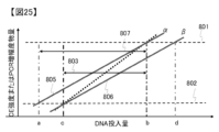
- FIG. 1 is a diagram showing the effect of the present invention.
- FIG. 2 is a schematic diagram of the obtained electropherogram.
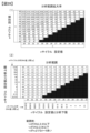
- 1 is an example of a table used for setting the number of cycles.
- 1 is an example of an analysis system.
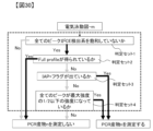
- 13 is an example of a method for determining data. 13 is an example of a method for determining data. 1 is an example of an analysis system. 1 is an example of an analysis system.
- This specification mainly describes procedures and standards for conducting human DNA testing, but the subject of analysis is not limited to human DNA testing.
- m and n refer to the number of thermal cycles in PCR. m and n are integers, and may be n-m ⁇ 2. In the following, a thermal cycle may be referred to as a PCR cycle or simply as a cycle.
- the mixture of PCR reaction reagents and sample-derived DNA will be referred to as the PCR reaction solution.
- the DNA from the sample that is amplified by the PCR reaction reagents will be referred to as the target DNA.
- PCR reaction solution m the PCR reaction solution obtained after m thermal cycles
- PCR reaction solution n the PCR reaction solution obtained after n thermal cycles
- the electrophoretic reagent may include deionized formamide, size standards, and pure water. Formamide and pure water may be included to lower the ionic strength of the electrophoretic sample or to denature DNA.
- the electrophoretic reagent may be a low-conductivity solution as well as formamide and pure water.
- a low-conductivity solution preferably has a conductivity of 10 mS/cm or less, more preferably 1 mS/cm or less, more preferably 100 ⁇ S/cm or less, and more preferably 10 ⁇ S/cm or less. The lower the conductivity of the solution used in the electrophoretic reagent, the greater the amount of DNA injected into the CE.
- a size standard may be mixed in to correspond to the detected peak and DNA length, or to estimate the amount of DNA contained in the electrophoretic sample from the detected peak.
- one example of an analytical system mixes a PCR reaction solution (e.g., at least one of a portion of PCR reaction solution m and at least a portion of PCR reaction solution n) with pure water, formamide, or a solution with a conductivity of 10 mS/cm or less to generate a mixture prior to electrophoretic analysis.
- a PCR reaction solution e.g., at least one of a portion of PCR reaction solution m and at least a portion of PCR reaction solution n
- pure water formamide
- a solution with a conductivity of 10 mS/cm or less to generate a mixture prior to electrophoretic analysis.
- the DNA obtained by the PCR reaction will be called the "amplification product”
- the amplification product obtained after m cycles will be called “amplification product m”
- the amplification product obtained after n cycles will be called “amplification product n”.
- PCR reaction procedure in which m cycles of PCR are performed, a portion of PCR reaction solution m is taken out, and the remaining PCR reaction solution m is subjected to n-m PCR cycles, and finally both PCR reaction solutions m and n are prepared, is referred to as "split PCR.”
- an allele refers to a genetic variant that can be distinguished at the same locus.
- amplicon refers to an amplification product with a single length.
- Amplicons of different lengths may be generated from one allele.
- multiple amplicons may be generated as by-products (artifacts) produced during the PCR reaction.
- one amplicon peak for one allele is often assigned to an individual's DNA, but in the case of mixed samples, it is difficult to distinguish between artifacts and amplicons derived from alleles, so amplicon peaks that may be artifacts may also be subject to analysis.
- CE analysis refers to the series of steps that involves preparing an electrophoretic sample, performing CE measurement, obtaining an electrophoretic pattern, and performing DNA identification or fragment analysis.
- the scope of "CE analysis” does not necessarily include some of the above steps.
- an electropherogram refers to a diagram obtained by CE measurement, with the horizontal axis representing time, or measurement point, or DNA chain length, and the vertical axis representing intensity.
- the vertical axis may represent wavelength, and the data may be three-dimensional data including intensity information.
- the vertical axis may also represent intensity, and the data may be three-dimensional data including dye information.
- An electropherogram obtained from electrophoretic sample m will be called “electropherogram m”
- an electropherogram obtained from electrophoretic sample n will be called “electropherogram n”.
- STR-CE refers to the series of steps from preparing the PCR reaction solution for STR-PCR, performing the PCR reaction, measuring the CE, and analyzing the resulting electropherogram.
- the data obtained from STR-CE may be an electropherogram or a DNA profile. Once STR-CE is complete, some or all of the data may or may not be provided to the user.
- analytical range refers to, for example, the range of a given sample amount or biomolecular weight within which an analysis can be performed correctly for a given sample or biomolecule, for an analytical system or for a part or multiple steps of an implementation procedure contained in an analytical system.
- “capable of analyzing correctly” may refer to a state in which all required conditions are met, but it is not necessary to meet all required conditions, and it may also refer to a state in which the best data possible for the system in question can be provided. For example, if the amount of sample given is extremely small, the data obtained will not be able to meet all required conditions, but it will be sufficient to obtain data that comes closest to meeting the required conditions.
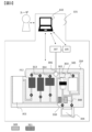
- the analysis system 101 may include a memory that stores program instructions, a control unit including a processor that executes the program instructions, a function that receives and analyzes raw data, optical data, and electropherogram data from the detection unit, a solution transport control mechanism such as a pump or valve, a CE unit (capillary electrophoresis unit) that performs electrophoretic analysis of the PCR reaction solution, a flow path device, and a heater.
- the control analysis unit may be connected to a network and may be capable of uploading, collating, and accessing data to a personal DNA database. For example, it may be connectable to CODIS (Combined DNA Index System).
- Various parameters related to the analysis protocol may be stored in advance in a database of a computer 102 provided in the analysis system 101. Based on the parameters recorded in the database 103, the computer may be responsible for opening and closing valves of the flow path device 104, the CE section 105 and their connecting sections, controlling the temperature, and controlling the applied pressure and/or flow rate.
- the parameters recorded in the computer 102 may include functions for setting parameters based on temperature, time, pressure, flow rate, stored parameters, and actual measured values.
- the flow path device 104 may be disposable. By making it disposable, contamination between samples can be prevented.
- the CE unit 105 may be disposable. Making it disposable helps prevent contamination between samples. In addition, since it can be molded integrally with the device, it is easy to store, maintain, and transport. The connection between the pretreatment unit and the CE unit is simplified, which helps reduce the frequency of breakdowns and errors.
- the CE section can be made to be reusable multiple times.
- the CE section requires precision manufacturing and has a high unit price, so making it reusable can help reduce costs.
- the computer 102 may be equipped with a user interface 106. Parameters related to the user interface 106 (e.g., time and temperature of each step, pressure, flow rate, procedure, amount of divided liquid, number of PCR cycles, sample information, cartridge information, analysis protocol, etc.) may be accepted from the user and stored in the database 103. In addition, various parameters may be stored in the database 103 in advance.
- the computer 102 may be responsible for opening and closing the valves of the flow path device 104, controlling the temperature, and controlling the applied pressure and flow rate based on the parameters recorded in the database 103.
- the flow path device 104 which is consumed for each measurement, has an internal tag, and the analysis system 101 can read the information on the tag to set an appropriate analysis protocol.
- the number of PCR cycles may be set by the user.
- the analysis system 101 stores the values of m and n that are set in advance.
- the user may also input information about the type of sample (e.g., cheek swab/touch sample/casework sample/DVI, etc.) and determine the appropriate PCR implementation procedure by comparing it with a database in the computer.
- the user may input whether to perform CE measurement on electrophoresis sample m first or on electrophoresis sample n first.
- the implementation procedure may also be automatically controlled in its entirety by the computer 102. The user may also assist and implement part of the analysis flow.
- StoA systems may be used in laboratories, crime scenes, police stations, hospitals, and automobiles.
- the flow channel device 104 refers to a disposable or multiple-use cartridge that contains a reagent, a chamber, and a flow channel.
- the flow channel device 104 may contain a power source for transporting a solution.
- some or all of the reagents may be present within the device.
- Some of the chambers may be equipped with a temperature control function, a molecular capture function, a detection function, and a voltage application function.
- the material used for the flow channel device is not particularly limited as long as it is a material commonly used in the technical field. It is preferable to use materials that have a low amount of DNA adsorption, such as polypropylene, cyclic olefin polymer (COP), cyclic olefin copolymer (COC), polycarbonate, polyethylene terephthalate, and polyurethane. It is also preferable to suppress the amount of adsorption by modifying the surface so that it is negatively charged.
- COP cyclic olefin polymer
- COC cyclic olefin copolymer
- polycarbonate polyethylene terephthalate
- polyurethane polyurethane
- materials include - metals such as gold, silver, copper, aluminium, tungsten, molybdenum, chromium, platinum, titanium, nickel; - alloys such as stainless steel, Hastelloy, Inconel, Monel, duralumin, etc.; -silicon; - glass materials such as glass, quartz glass, fused silica, synthetic quartz, alumina, sapphire, ceramics, forsterite and photosensitive glass; Plastics such as polyester resin, polystyrene, polyethylene resin, ABS resin (Acrylonitrile Butadiene Styrene resin), dimethylpolysiloxane (PDMS), nylon, acrylic resin, fluororesin, polycarbonate resin, polyurethane resin, methylpentene resin, phenolic resin, melamine resin, epoxy resin and polyvinyl chloride resin; - agarose, dextran, cellulose, polyvinyl alcohol, nitrocellulose, chitin, chitosan, Or any combination of these.
- a typical chamber or reagent reservoir is a space that can contain liquids or solids and where solutions can be reacted, held, heated, or transformed.
- the chamber may have a larger diameter than the flow channel, but may be indistinguishable from the flow channel by appearance.
- the chamber may have a membrane or microstructure inside, may be made of a different composition than the flow channel, may have a different surface treatment, or may have a different hydrophilicity.
- the flow channel device may also have a heater or laser light source on the outside. Reagents may be stored in the chamber, and PCR, lysis, purification, etc. may be performed in the chamber.
- a typical chamber volume is preferably 0.01 ⁇ L to 50 mL.
- the flow path device may store reagents within the device, or the reagents may be supplied from outside the flow path device or from inside the analysis system.
- the device stores one or more types of reagents in one or more reagent storage sections.
- the reagents include at least one of the following: [lysis solution, cleaning solution, PCR reagents (which may contain polymerase, primers, surfactants, etc.), formamide, pure water, DNA fragments, and oil]. Since unintended mixing of these can lead to a decrease in performance or other unexpected results, it is desirable that they are separated by a partition mechanism consisting of a valve, film, air, or a flow path thin enough to prevent spontaneous mixing, or a combination of these, until just before use.
- reagents by isolating the reagents from the outside air, long-term storage and portability of the device are achieved.
- the same reagent may be stored in multiple reagent storage sections to be released in multiple steps.
- reagents when reagents are stored outside the device, they are desirably stored in a state isolated from the outside air, and are separated from other purification system components by valves, films, air, etc.
- Known reagent storage technologies include, for example, a blister reagent storage unit or the reagent storage unit installed in Patent Document 1 and Patent Document 2, and similar configurations may be incorporated into this embodiment.
- sample type The sample to be subjected to the purification system according to the present embodiment is not particularly limited as long as it is a biological sample.
- the biological sample is also not particularly limited, and samples derived from any biological organism such as vertebrates (e.g., mammals, birds, reptiles, fish, amphibians, etc.), invertebrates (e.g., insects, nematodes, crustaceans, etc.), plants, protozoa, fungi, bacteria, and viruses can be used.
- vertebrates e.g., mammals, birds, reptiles, fish, amphibians, etc.
- invertebrates e.g., insects, nematodes, crustaceans, etc.
- plants protozoa, fungi, bacteria, and viruses
- a swab, filter paper, cloth, etc. When collecting a sample, a swab, filter paper, cloth, etc. can be used as a carrier, and the carrier itself can be introduced into the purification system.
- Forensic samples include cheek swabs, bone, muscle tissue, human organs, touch samples containing very small amounts of DNA, bloodstains, skin fragments, hair, bodily fluids, and items presumed to contain any of these. Many forensic samples contain unknown amounts of DNA, ranging from 0.001ng to 1000 ⁇ g of DNA, more frequently 0.01ng to 10 ⁇ g of DNA. Forensic samples may contain only DNA from a single individual, may contain DNA from multiple individuals, and may contain degraded DNA.
- the analysis system 101 may include a pump and a valve for transporting the solution.
- the transport means may be a syringe pump, a diaphragm pump, an electrochemical pump, passive transport using surface tension, centrifugal force, or a combination thereof.
- the analysis system 101 may be equipped with a valve.
- the valve is used to specify the solution transport path as well as to switch the path to which air pressure is applied.
- the valve may be a diaphragm valve that operates with air pressure, a mechanical valve, or a valve that uses surface tension.
- the flow path that can be transported may be switched based on the difference in pressure required for transport.
- the device may contain PCR reagents.
- the PCR reagents may be prepared as separate solutions containing polymerase and primers.
- the PCR reagents may be dry reagents.
- the sample itself such as a swab, may be subjected to PCR.
- DNA purified with silica, Chelex, phenol chloroform, etc. may be mixed with the PCR reagents.
- a membrane (such as a silica membrane) with trapped DNA may be mixed with the PCR reagents.
- the PCR reagent may include an IPC that is amplified along with the sample DNA and a set of primers for amplifying the IPC.
- the primers for the IPC may be dyed and detectable by CE.
- the amplicons derived from the IPC can be used for analysis.
- the amount of DNA in the sample may be estimated by using the intensity ratio of the IPC and sample-derived peaks, the amplification efficiency correction factor, and the fluorescence intensity correction factor. Also, by checking the intensity of the IPC, it may be estimated whether the PCR reaction is proceeding normally or has been inhibited.
- the typical volume of PCR reaction solution is 1 ⁇ l to 200 ⁇ l, and more preferably 10 ⁇ l to 50 ⁇ l.
- a small volume of solution has the advantages of allowing accurate temperature control, high-speed PCR, and low reagent costs.
- a larger volume of solution allows for more eluted DNA to be received.
- a typical PCR reaction may consist of an initial denaturing step, an annealing step, an extension step, a denaturation step, and a final extension step, or some of the steps may be missing.
- the mixture is heated to 90°C to 99°C for 1s to 2 minutes at the start of PCR, allowing the PCR reaction to begin.
- the mixture is heated to 50°C to 80°C for 1s to 2 minutes to allow the primers to bind to the template DNA.
- the extension step the mixture is heated to 50°C to 80°C for 1s to 2 minutes to raise the temperature to a level where DNA polymerase can work well, allowing the DNA to elongate.
- the mixture is heated to 80°C to 99°C for 1s to 2 minutes.
- the final extension step the mixture is heated to 50°C to 80°C for 1min to 60min.
- CE may involve injecting the amplified product into a polymer-filled capillary tube using voltage injection. Furthermore, when a high voltage is applied to both ends of the capillary, the fluorescent DNA fragments are separated by size and detected by a laser/camera system.
- MPS massively parallel sequencing
- pyrosequencing pyrosequencing
- Sanger sequencing nanopore sequencing
- chromatography e.g., methanol
- electrical measurements spectroscopy
- NMR RFLP (Restriction Fragment Length Polymorphisms)
- microarrays e.g., etc.
- the signal obtained in the CE section is analyzed in the analysis section.
- Known analysis software includes GeneMapper (registered trademark) ID, GeneMapper ID-X, GeneMarker (registered trademark) HID, i-Cubed (trademark), OSIRIS, TrueAllele (trademark), etc.
- a graph is generated based on the size standard peak from the signal intensity vs. time information, with the horizontal axis representing DNA length and the vertical axis representing intensity. Cosmic rays and pull-up/pull-down may be corrected. Baseline correction may be performed, or an electropherogram may be obtained using other existing techniques. Peak detection is performed on the obtained electropherogram to examine the intensity and peak position of each amplicon.
- the analysis may be performed partially with human intervention or fully automatically.
- Macrosatellites are DNA loci that contain repeated base sequences with 2-7 nucleotides per repeat unit. The number of repeats at a particular locus varies from individual to individual, and can be detected as differences in the length of the amplified products by STR-PCR.
- a typical STR-PCR analysis detects two or more loci. Typically, five or more, 10 or more, 15 or more, 20 or more, or 25 or more loci are included.
- STR-PCR may be performed using kits sold by GlobalFiler (trademark) or PowerPlex (registered trademark). It is also preferable to include loci designated by various genetic databases, such as CODIS, for forensic or DNA identification purposes in each country. The loci may include loci present on autosomes, or may include genes present only on the Y gene.
- the number of peaks detected will, unless the amount of DNA is degraded or insufficient, at a minimum correspond to the number of loci in the kit, and at a maximum correspond to a peak corresponding to the sum of twice the amount of genes assigned to the autosomes and the number of genes assigned to the sex chromosomes among the loci in the kit.
- one fluorescent dye is assigned to one locus.
- STR-PCR kits with 2, 3, 4, 5, 6, 7, or 8 dyes may also be used.
- a combination of length and peak color information may be used to assign loci to detect DNA types. Thresholds for the intensity and position of various peaks may be set for each color, or for each locus or allele.
- a DNA profile derived from a single individual one or two alleles are detected per locus.
- a DNA profile derived from a mixed sample derived from multiple individuals one or two or three or more alleles are detected per locus.
- a probabilistic analysis is typically performed based on the peak intensity ratio. Examples of programs for analyzing mixed samples include Kongho, LikeLTD, LRmix, STRmix, Euroformix, and TrueAllele.
- artifacts refer to, for example, peaks that are not derived from the DNA type derived from an individual, a balance between peaks that is different from the ideal state, or a peak shape that is different from the ideal state, which can cause the electropherogram and DNA profile obtained during actual DNA analysis to differ from the ideal electropherogram and DNA profile that should be obtained from the DNA type derived from an individual.
- the DNA type that should be obtained may not be detectable, resulting in a reduced amount of information being obtained.
- this state is called a drop in.
- a peak that should be present in an individual's DNA is not detected during CE analysis and is not reflected in the analysis results, this state is called a drop out. It is preferable to set various thresholds to minimize the occurrence of drop in and drop out.
- Stutter peaks are by-products of PCR amplification. They arise when one or more repeat sequences are skipped or overlapped during the extension reaction. Stutter peaks typically appear before or after the sample peak, and appear one or two repeats more or less than the sample peak. Typically, stutter peaks have an intensity of about 1-20% of the sample peak.
- various PCR parameters such as the number of PCR cycles, the final extension time, and the amount of input DNA are adjusted so that the A-peak and A++ peak are within a range of 50% or less, more preferably 20% or less, and more preferably 10% or less, relative to the A+ peak intensity.
- An IAP intensity threshold or an intensity ratio threshold to the main peak may be set to determine whether the intensity of the A-peak or A++ peak falls within the above range and suitable STR-CE has been performed. If the intensity ratio of the A- or A++ peak to the A+ peak is greater than a certain level, the intensity of the main peak will not reflect the original abundance ratio of the gene. In addition, in the case of a mixed sample or when a peak with one base shift appears due to genetic polymorphism, accurate assignment will not be possible. It may also cause the detection of an incorrect DNA type.
- the ratio of the intensity of the smaller peak to the larger peak (Peak to height ratio, PHR) of the two peaks is 10% or more, more preferably 40% or more, and more preferably 60% or more.
- the ratio of dNTPs and polymerase to the amplicon decreases, and the tendency for short DNA to be preferentially amplified increases.
- the electropherogram obtained has a sloped electropherogram with a small peak for long DNA and a large peak for short DNA.
- the ratio of short DNA to long DNA tends to be higher.
- a DNA profile with a slope is also obtained.
- an inhibitor is included, the amplification efficiency of long DNA tends to be lower than that of short DNA, which also gives a DNA profile with a slope.
- the PCR reagent when the PCR reagent is diluted with the DNA solution more than the original mixing ratio, the amplification efficiency differs, and long DNA is preferentially amplified, giving a DNA profile with a reverse slope.
- a reaction system in which long DNA is preferentially amplified is obtained, and a DNA profile with a reverse slope is obtained.
- a profile with a slope or a profile with a large peak intensity ratio between gene loci is not desirable. This is because the difference in peak intensity becomes larger, and peaks that saturate CE or fall below the detection limit become more likely to appear. Also, it becomes difficult to assign mixed samples.
- Inter locus PHR inter-locus peak intensity ratio
- the PCR reaction parameters it is desirable to adjust the PCR reaction parameters so that the inter-locus peak intensity ratio (Inter locus PHR) has an intensity of 1% or more, more preferably 5% or more, more preferably 10% or more, and more preferably 20% or more relative to the maximum peak. Also, small peaks that do not meet the Inter locus PHR threshold may be excluded from peak analysis. Also, to deal with degraded DNA, it is desirable that the PCR amplification amount is within an appropriate range for STR-CE or that the dynamic range of CE is designed to be large.
- OS oversaturation
- Pull-up peaks are peaks that are derived from other dyes and are detected incorrectly. Pull-ups are particularly noticeable when CE is saturated, but they can also be detected when CE is not saturated.
- air bubbles in the CE section and background noise in the detection section may be reflected in the electropherogram.
- An analytical threshold may be set during analysis to prevent noise peaks from being mistakenly used in the analysis.
- the analytical threshold may be set by measuring background noise to obtain a sufficient signal-to-noise ratio, or may be set by the user, set by the device for each experiment, or may be preset.
- a program may be stored and executed to determine whether a peak that exceeds the AT is due to an amplification product, poor CE migration, or various types of CE noise.
- the AT may be set in two or more stages, a first and a second reference value. If the peak has a peak intensity greater than the first reference, it is determined to be a true peak, and if the peak has an intensity greater than the second reference and less than the first reference, review by the user or an expert is required, or it may be set to be determined to be a peak when other set conditions are met. In addition, since amplification efficiency may differ depending on the gene locus, and luminescence efficiency and noise intensity may differ depending on the dye, AT may be set for each gene locus or each dye.
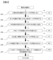
- Figure 2 shows an evaluation flow for determining whether the obtained DNA profile is a Full profile or for informing the user of the quality of the data. This chart is one example, and the order may be reversed, some steps may be omitted, steps not shown here may be included, and some or all of the steps may be performed simultaneously so that multiple flags are assigned. Also, a flow like that of Figure 2 may be performed for each peak or locus, and it may be determined to be a Full profile if all criteria are met for all loci. Even if it is not a Full profile, information on only the loci that met the criteria may be provided to the user. Also, it may be possible to provide a table or other output showing which criteria were or were not met for each locus.
- loci should have at least one peak above AT. If there are loci where no peaks are detected, the loci or analysis results may be flagged as Drop out (DO).
- DO Drop out
- That peak should have an intensity at least twice that of AT (excluding genes that are uniquely detected, e.g. sex chromosome loci). If there is no intensity at least twice that of AT, the peak, locus, or analysis result will be flagged as inconclusive homozygous (IH flag).
- All detected peaks must be at DNA chain lengths that can be assigned to a DNA type. If a peak cannot be assigned and does not fall under IPA, it will be recognized as an Off Ladder (OL) peak, and an OL flag will be assigned to the peak, locus, or analytical result. However, peaks that appear at the position of a stutter peak do not need to be considered for OL judgment.
- OL Off Ladder
- the third-highest peak should be 1% or less, 5% or less, 10% or less, 20% or less, or 40% or less intense than the second-highest peak. If the ratio of the intensity of the third-highest peak to the intensity of the second-highest peak exceeds a threshold, the DNA contained in the sample may be determined to be from two or more individuals and a Mix flag may be set. However, if the third-highest peak occurs at the position where the first or second stutter peak appears, it may be determined to be a stutter peak.
- a peak appears at the stutter peak position with an intensity of 1% or less, 5% or less, 10% or less, 15% or less, 20% or less, or 40% or less intense than the main peak, it may be determined to be a stutter and a Mix flag may not be set. If a peak exists at a position that could be a stutter peak, and its intensity exceeds the threshold of the acceptable range for stutter peaks, it may be a Mix, so a Mix flag may be set. Also, if the intensity of the peak with the third highest intensity in a position where a stutter peak should not appear exceeds the threshold, a Mix flag may be set. A similar determination may be made for peaks with the fourth, fifth, and subsequent intensities.
- the PHR is determined to be poor and a PHR flag may be assigned.
- a peak that gives an IPA flag also gives an OL flag, so the criterion 205 may also serve as 204, i.e., the IPA flag may include the OL flag.
- a full profile will be obtained. If a full profile cannot be obtained, an expert review may be requested. In this case, it may take longer to complete the DNA analysis. Therefore, it is necessary to increase the probability of obtaining a full profile by setting an appropriate number of cycles. Also, if the sample is originally mixed, the amount is small, there is a lot of PCR inhibitors, a full profile cannot be obtained but not all loci are detected normally, etc., it can be useful in criminal investigations if 5 or more or 10 or more loci are detected. Such a DNA profile is called a partial profile. The more information on loci obtained, the more useful it is for criminal investigations.
- the analysis protocol especially the number of PCR cycles, must be set so that as many peaks as possible can be detected.
- the protocol especially the number of PCR cycles, must be set so that as many peaks as possible can be detected while the electropherogram satisfies 201, 205, and 206 (i.e., these flags are not given).
- a threshold may be set to determine whether DO is due to the absence of the relevant allele in the DNA input to the PCR reaction, or due to a low number of PCR cycles. For example, if there is a locus with no peaks above AT, and there is a peak in the entire amplified product that is 10 times higher than AT, it may be determined that the DO is due to the sample; if not, it may be determined that the DO is due to a low number of PCR cycles, or that it cannot be due to the sample. This determination can be used to determine whether an analysis with an increased number of PCR cycles should be performed.
- factors that can cause intensity variations include: (1) variations in the concentration of salts and injection-inhibiting substances contained in the PCR reaction solution, (2) the mixing ratio of the electrophoresis reagent and the PCR reaction solution, (3) amplification efficiency, (4) deterioration of the electrophoresis reagent or incomplete denaturation, (5) temperature variations in the electrophoresis area, (6) variations during electrolytic injection, (7) variations between capillaries and capillary arrays, and (8) detection intensity variations in the detection area.
- the dynamic range of CE may be the dynamic range described in the manuals set for various CE devices, or it may be the ratio of the maximum amount of amplicon to the minimum amount of amplicon that gives a linear signal relative to the amount of amplicon actually input into CE, or it may be the maximum amount of amplicon to the minimum amount of amplicon that allows the relative ratio of the amount of amplicon input into CE to be assigned from the signal intensity, or it may be the ratio of an arbitrary upper analytical limit to an arbitrary lower analytical limit. It may also be the ratio of OT to AT. It may vary for each measurement.
- the analytical range of STR-CE may simply correspond to the dynamic range of CE, or may be an experiment in which the amount of DNA put into PCR is changed to examine the amount of DNA at which a specific allele can be correctly detected, or may be an experiment in which the amount of DNA put into PCR is changed to examine the amount of DNA at which a specific allele set can be correctly detected, or such a range of DNA amounts may be examined in experiments for multiple different individuals, and the average, minimum, or maximum range may be used as the analytical range.
- the amount of DNA used for CE measurement is generally proportional to the amount of DNA put into STR-PCR, but this is not always the case because the CE injection efficiency depends on the DNA concentration, and the PCR amplification efficiency depends on the DNA concentration and the number of cycles.
- the analytical range of STR-CE does not change significantly in most cases, but it may deviate, especially when the amount of DNA is reduced, due to the occurrence of a stochastic effect (a stochastic effect in which the amount of DNA corresponding to the locus to be amplified is no longer proportional to the amount of DNA input).
- the dynamic range of CE and the analytical range of STR-CE may be evaluated taking into account the variability of (1) to (8) listed above.
- the analytical range of an analytical system refers to, for example, the range of DNA contained in a sample that allows DNA analysis to be performed correctly for a DNA sample input into the analytical system.
- expanding the analytical range of STR-CE it is possible to improve the dynamic range and sensitivity of CE, reduce the variability of STR-CE, prepare multiple cycles of amplification products, prepare eluates with different dilution rates and subject each to STR-CE, etc.
- the volume or mesh of the purification membrane can be reduced so that the upper limit of the amount of DNA that can be processed by the purification membrane can be cut off, or the dilution rate can be changed by quantifying after purification.
- Fig. 3 shows an example of the analysis system 101.
- Fig. 4 shows an example of the operation procedure of the analysis system 101.
- the biomolecule analyzer includes a computer 102 for performing biomolecule analysis, and a flow path device 104.
- the flow path device 104 includes a dissolution chamber 301 for introducing and dissolving the collected sample, a purification membrane chamber 303 containing a purification membrane 302, a PCR chamber 304 (a PCR chamber for performing a thermal cycle) for amplifying DNA, and a waste liquid chamber 305.
- An external connection port 306 is provided that is fluidically connected to the outside of the device. The solution is transported through the external connection port 306, and reagents, amplified products, etc. can be exchanged with the outside of the device.
- the liquid transfer may be controlled using a pump and valve 307.
- the pump and valve 307 may all be provided outside the flow path device, or some of them may be provided inside the flow path device 104.
- the PCR reagent storage section 308 may be provided with PCR reagents 309 (polymerase, primer, dNTP, buffer, etc.) required for the PCR reaction, and the migration reagent storage section 310 may be provided with migration reagent 311.
- the chamber includes reagent reservoirs 312, 313, and 314 for storing reagents necessary for pretreatment.
- a lysis buffer is transported from the reagent reservoir 312 to the lysis chamber 301.
- lysis begins in a lysis step 402.
- a purification step 403 the lysis product is transported from the lysis chamber 301 to the purification membrane chamber 303, where the DNA is bound to the purification membrane 302, and a cleaning solution is released from the reagent reservoir 313, and purification is performed. After purification, a step of drying the cleaning solution and the like may be included. An elution solution is released from the reagent reservoir 314, and the DNA eluted from the purification membrane chamber 303 is transported to the PCR chamber 304. A PCR reagent is transported from the PCR reagent reservoir 308 to the PCR chamber 304 and mixed with the eluted DNA.
- the purified DNA in the PCR chamber 304 is mixed with a PCR reagent 309 and subjected to a PCR reaction.
- the amplified DNA is mixed with the migration reagent 311 stored in the migration reagent storage section 310, and measurement is performed in the CE section 105.
- a step can be added in which the mixture is heated to 80-100°C and then rapidly cooled to 0-10°C before CE analysis. By adding this step, the DNA is more completely converted into single strands, enabling highly accurate CE analysis.
- Example of analysis system used in this embodiment shows an outline of the analysis system 101 of this embodiment (FIG. 5(1)) and an example of an operation procedure (FIG. 5(2)). Operation steps 501 to 507 may correspond to the amplification step 404 and the detection step 405.
- the analysis system 101 of this embodiment has a flow path device 104 and a CE section 105, and the flow path device is equipped with a PCR chamber 304.
- the analysis system 101 also has a dispensing chamber 320.
- a PCR reaction solution or an electrophoresis sample is sent to the dispensing chamber 320.
- the dispensing chamber 320 may be omitted.
- Each element is connected by flow paths 315, 316.
- the analysis system 101 prepares a PCR reaction solution in step 501, performs m PCR cycles in the PCR chamber 304 in step 502, and then removes a portion of the amplified product from the PCR chamber 304 as PCR reaction solution m without changing its composition in step 503, performs CE measurement on the electrophoresis sample m in the CE unit 105 in step 504, and performs thermal cycling n-m times on the PCR reaction solution m remaining in the PCR chamber 304 in step 505 to obtain a PCR reaction solution n.
- step 506 a portion of the PCR reaction solution n is removed from the PCR chamber 304 without changing its composition, and performs CE measurement on the electrophoresis sample n in the CE unit 105 in step 507.
- the dispensing step in step 506 may be omitted, and all of the amplification products from n cycles may be mixed with the electrophoresis reagent in step 507.
- Steps 503 to 505 can be repeated multiple times to increase the number of divisions to three, four, or more.
- Steps 504 and 507 may be performed simultaneously, or 507 may be performed after 504. By performing 507 after 504, the setting of 505 can be changed depending on the result of 504.
- the analysis system 101 may be equipped with heating units 317 and 318 (temperature control/heating mechanism) for performing thermal cycling in the PCR chamber 304.
- a flow path 319 and a flow path 315 are connected to the PCR chamber 304, and the supply of reagents and pressure may be controlled.
- the analysis system 101 may be equipped with a pump and valve 307 for performing solution transport suitable for various steps such as a flow path device and CE measurement. As shown in FIG.
- the analysis system 101 may be equipped with a computer 102, which may be equipped with a function of controlling the pump and valve 307, controlling the CE measurement, controlling temperature, analyzing data obtained from the CE unit 105 and the heating units 317 and 318, feeding back the data, providing the data to the user, and the like.
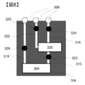
- the flow path device may be equipped with a dispensing chamber 320.
- the dispensing chamber 320 has a function of taking out a part of the amplified product from the PCR chamber 304 without changing the composition at the timing when m thermal cycles are completed.
- the dispensing chamber 320 may have a measuring function for extracting a specified amount of the PCR reaction liquid m or n.
- the dispensing chamber 320 may suck up the PCR reaction liquid, or the PCR reaction liquid may be sent to the dispensing chamber 320 by pressurization.
- the dispensing chamber 320 may be provided simply to temporarily store the PCR reaction liquid, and may not have a measuring function.
- the dispensing chamber 320 may be provided outside the flow path device 104.
- the analysis system 101 may have a waiting section 321 between the CE section 105 and the PCR section.
- the waiting section 321 may temporarily hold the PCR reaction solution or the electrophoretic sample in which the PCR reaction solution and formamide are mixed from step 506 to 507 or from 503 to 504.
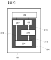
- the flow path device in FIG. 6 (and the following figures) may be arranged vertically, that is, so that the main part of the flow path or at least a part of the flow path is parallel to the direction of gravity. In one form of the flow path device, the bottom side of the figure is used facing downward in the direction of gravity. By using it vertically, air bubbles/mixed air in each chamber accumulate at the top of the chamber, so that when transporting to the next chamber/flow path, the solution is removed from the bottom, minimizing the mixing of air into the next step.
- the flow path device can be modified as follows:
- the flow path device may include a mixing chamber 327 between the dispensing chamber 320 and the external connection port 306.
- the PCR reaction solution in the dispensing chamber 320 may be mixed with the electrophoresis reagent in the mixing chamber 327.
- the mixing chamber 327 may be connected to the dispensing chamber 320 by a flow path 328.
- the mixing chamber 327 may be provided outside the flow path device, inside the analysis system 101, and in some cases, the standby unit 321 may take on this role.
- a flow path 329 is connected to the mixing chamber 327, and air bubbles may be sent into the mixing chamber 327 for mixing by applying pressure to the flow path 329, or the electrophoresis sample may be sent to the CE unit 105.
- the PCR chamber 304 may have three flow paths 319, 315, and 330.
- the flow path 319 may be connected to the upstream side of the sample, the flow path 315 to the dispensing chamber 320, and the flow path 330 to the mixing chamber 327.
- the PCR reaction liquid m taken out from the PCR chamber 304 may be transported to the mixing chamber 327 via the dispensing chamber 320, and the PCR reaction liquid n taken out from the PCR chamber 304 may be transported to the mixing chamber 327 via the flow path 330 without passing through the dispensing chamber 320. Since the PCR reaction liquid m and the PCR reaction liquid n pass through different paths, it is possible to suppress the decrease in reproducibility caused by the remaining liquid.
- reaction liquid n is measured and the reaction liquid m is not measured and the entire amount is transported to the mixing chamber 327 or the CE unit 105, there is no need to transport the reaction liquid m to the dispensing chamber 320, so this flow path device structure makes it easier to perform split PCR.
- PCR reaction liquid m is also to be measured, another dispensing chamber may be provided in addition to the dispensing chamber 320 used for PCR reaction liquid n.
- the flow path device 104 may have electrophoretic reagent storage sections 310 and 331 for storing electrophoretic reagents (formamide, DNA fragments, pure water, etc.).
- the electrophoretic reagent storage sections 310 and 331 may be located on the flow path 315 or on the flow path 319.
- the reagent storage section may be divided into two or more storage sections for one type of reagent as shown in FIG. 10. By dividing into two, a specified amount of reagent can be released from each storage section at the time of division. Alternatively, the amount of liquid released from the storage section may be controlled so that the reagent can be released in two or more separate times from one reagent storage section. As shown in FIG.
- the flow path device 104 may have air storage sections 332 and 333.
- the air storage sections 332 and 333 may be located on the flow path 315 or on the flow path 319.
- a specified amount of PCR reaction liquid can be transported outside the PCR chamber 304.
- mixing chamber 327 may also serve as dispensing chamber 320.
- Air reservoir 332 or 333 may contain a liquid that does not affect the PCR reaction, such as oil, instead of air. Air reservoir 332 or 333 may be filled with PCR reaction liquid, and the PCR reaction liquid may be newly replenished with a volume equivalent to the pushed-out PCR liquid.
- This section describes a method for performing split PCR on the flow path device 104. Although a dispensing chamber is mentioned in various places, a solution may be directly transported to the CE section 105 without using a dispensing chamber/mixing chamber.
- FIG. 12 shows an example of a flow path device 104
- FIG. 13 shows an example of a transport method for performing split PCR on the flow path device of FIG. 12.
- some reference numerals are shown in FIG. 12 but omitted in FIG. 13.
- Step I There is a PCR chamber 304 containing a PCR reaction solution 335, and m cycles of PCR reaction are carried out in the PCR chamber 304 with valves 326, 323, and 325 closed. This step may correspond to step 502.
- the analysis system 101 performs m thermal cycles on the PCR reaction solution 335 in the PCR chamber 304 to generate PCR reaction solution m (first reaction solution).
- Step II After m cycles of PCR reaction are completed, valves 326 and 323 are opened to transfer a portion of the solution in PCR chamber 304 to dispensing chamber 320. This step may correspond to step 503.
- the flow path device 104 has valves 326, 323 that can be opened and closed, and a portion of the PCR reaction solution m is divided and removed by closing the valves 326, 323 before the start of m thermal cycles and opening the valves 326, 323 after the end of m thermal cycles. In this way, the division process can be carried out appropriately.
- Step IV Open the valve 325 and transport the electrophoretic sample in the mixing chamber 327 to the outside of the flow path device 104 (to the standby section 321 or CE section 105 of the analysis system). This step may correspond to step 504.
- Step V Close valve 326 and perform thermal cycle n-m times. This step may correspond to step 505.
- the analysis system 101 performs n-m thermal cycles (where n-m is an integer of 2 or greater) on the PCR reaction liquid m remaining in the PCR chamber 304 so that the total number of thermal cycles is n, to generate PCR reaction liquid n (second reaction liquid).
- Step VI After a total of n thermal cycles are completed, close valve 325, open valves 326 and 323, and transport PCR reaction solution n to mixing chamber 327.
- the analysis system 101 may perform electrophoretic analysis of at least a portion of the PCR reaction solution n in the CE section 105.
- FIG. 14 shows the analysis process of split PCR
- Fig. 15 shows an example of a flow path device 104
- some reference symbols are shown in Fig. 15 but omitted in Fig. 16.
- the flow path device 104 has a valve 337 on the flow path 315 that connects the dispensing chamber 320 and the PCR chamber 304.
- the valve 337 is installed on the PCR chamber 304 side of the branch with the migration reagent storage section 310.
- a valve 338 is also installed in the flow path 316.
- a valve 339 is also installed on the flow path 319, on the flow path 329 side of the branch with the migration reagent storage section 331.
- Step I All valves are closed. There is a PCR chamber 304 containing a ⁇ l of PCR reaction solution 335, and 24 thermal cycles are performed in the PCR chamber 304. After completing the 24 thermal cycles, a final extension is performed for 8 minutes. (Steps 601 to 604 may correspond to steps 501 and 502.)
- Step II After 24 cycles of PCR reaction are completed, valves 326, 323, and 337 are opened, and a portion of the solution in PCR chamber 304, b ⁇ l (where a>b), is transported to dispensing chamber 320 via flow path 315. (This may correspond to step 605 or step 503.)
- Step III Valves 323, 326, and 337 are closed, and valves 324 and 325 are opened, pushing out c ⁇ l migration reagent 311 from migration reagent reservoir 310, and transporting PCR reaction solution m stored in dispensing chamber 320 to mixing chamber 327. PCR reaction solution m is mixed with migration reagent 311 to become migration sample 336. (This may correspond to step 606 or step 504.) At this time, migration reagent 311 may remain in part of dispensing chamber 320 and flow path 315.
- Step IV Close valve 324, open valve 338, and transport the electrophoretic sample in the mixing chamber 327 to the outside of the flow path device 104 (to the standby section 321 or CE section 105 of the analysis system). (This may correspond to step 607 or step 504.)
- Step VI After a total of 30 thermal cycles are completed, open valves 326, 323, and 325 to push out d ⁇ l of electrophoretic reagent from electrophoretic reagent reservoir 331, and transport PCR reaction solution n to mixing chamber 327. (This may correspond to step 506.)
- Step VII Valve 325 is closed, valve 339 is opened, and air pressure is applied to send all the solution remaining in the PCR chamber 304 to the mixing chamber 327. Air may also be sent into the mixing chamber 327 to agitate and homogenize the electrophoresis sample 336. (This may correspond to step 611 and step 507.)
- Step VIII Open the valve 338 and transport the electrophoretic sample in the mixing chamber 327 to the outside of the flow path device 104 (to the standby section 321 or CE section 105 of the analysis system). (This may correspond to step 612 or step 507.)
- step 605 the temperature of the PCR chamber 304 during dispensing may be set to any temperature between room temperature and denaturation.
- the solutions may be kept at low temperatures (4°C). Keeping the solutions at low temperatures can prevent deterioration of the samples and the progression of unnecessary reactions.
- step 605 it is preferable to set the temperature during division to the same temperature as the denaturation step, as this prevents unnecessary extension reactions and suppresses the occurrence of artifacts.
- step 605 if the temperature during division is set to be equal to the extension temperature, an unnecessary extension reaction occurs, but non-specific amplification can be suppressed. This is also preferable because it avoids inactivation of the polymerase and fluorophore. The impact of the unnecessary extension reaction on the analytical accuracy of STR-CE can be ignored.
- the temperature during division may be between the extension temperature and RT. In this case, precise temperature control is not required, which is convenient. Since there are sufficient amplicons at the time when m cycles of PCR are completed, the effect of non-specific amplification can be ignored.
- step 605 the shorter the time required for division, the better. If the division takes a long time, there is a possibility that artifacts will increase. In addition, the longer the division takes, the greater the risk of inactivation of various biomolecules, such as polymerase.
- the analysis system 101 does not perform analysis by a method other than electrophoretic analysis on each reaction solution (including a part of PCR reaction solution m and at least a part of PCR reaction solution n) before electrophoretic analysis. This simplifies the configuration of the device, and, for example, does not require an additional optical system.
- the volume of PCR reaction solution used in this flow path device is 1 ⁇ l to 200 ⁇ l, and more preferably 10 ⁇ l to 50 ⁇ l.
- the smaller the volume of solution the more accurate and faster the temperature control can be.
- the larger the volume of solution the more purified DNA can be accommodated, making it easier to achieve high sensitivity.
- the larger the volume of solution the less precise the measurement of the solution becomes when dividing.
- Table 2 shows an example of the amount of liquid when divided. The amount of liquid actually measured does not have to be the value in the table, and the median value when multiple measurements are taken can be the value in the table.
- the total amount of PCR reaction solution is a ⁇ l
- the amount of solution removed during cycle m in step 503 is b ⁇ l
- the amount of migration reagent mixed with PCR reaction solution m in step 504 is c ⁇ l
- the amount of migration reagent mixed with PCR reaction solution n in step 507 is d ⁇ l.
- Table 2 above shows an example of a suitable relationship or set value for a-d.
- it is necessary that the ionic strength of the migration sample is sufficiently low. Therefore, it is preferable to mix the amount of migration reagent in a volume ratio of 2, 5, 10, 20, etc., greater than the amount of PCR reaction solution.
- the PCR division can be set so that PCR reaction solution m and PCR reaction solution n are equal. If the amounts of PCR reaction solution m and n are close, stable delivery of the electrophoresis reagent to the CE section can be achieved.
- the PCR division can be set so that PCR reaction solution m is smaller than PCR reaction solution n.
- Set 1 is an example of the solution volume when the amount of electrophoresis reagent is set to 10 times the amount of PCR reaction solution.
- Set 2 is an example of the amount of solution when the amount of PCR reagent is 15 ⁇ l, 5 ⁇ l of solution is taken out at the time of division into m cycles, and the entire amount of PCR reaction solution is mixed with the electrophoresis reagent at the time of n cycles.
- the analysis system 101 transports the entire amount of PCR reaction solution in the PCR chamber out of the PCR chamber at the end of n thermal cycles. In this way, the device required for measurement can be omitted, and the configuration of the flow path can be simplified.
- the migration reagent is left in the dispensing chamber 320. If the amount of migration reagent in the migration reagent storage section 310 is sufficiently large compared to the dispensing chamber 320, the influence on the analytical accuracy and range can be ignored even if the migration reagent is left in the dispensing chamber 320. In addition, if a flow path 322 is provided as an air line between the valve 337 and the dispensing chamber 320 on the flow path 315, or an air storage section 334 is provided, the entire amount can be pushed into the dispensing chamber 320 and the mixing chamber 327.
- Set 3 is an example of the amount of solution stored in the migration reagent reservoir 310 when it is anticipated that e ⁇ l of migration reagent will remain in the dispensing chamber 320.
- Set 4 is an example of the amount of solution stored in the electrophoretic reagent storage section 310 when the volume of the dispensing chamber 320 is b ⁇ l and it is expected that b ⁇ l of electrophoretic reagent will remain in the dispensing chamber 320.
- Measurement may be performed when dispensing PCR reaction solution m in step 503 and when dispensing PCR reaction solution n in step 506. If step 506 is omitted and the entire amount of PCR reaction solution n is mixed with the electrophoresis reagent, measurement may be performed only in step 503. In other words, the number of measurements may be the number of divisions minus 1. Similarly, if measurement is performed twice, since there is a specified amount of liquid in the PCR chamber, an additional p PCR thermal cycles may be performed on the reaction solution remaining in the PCR chamber, and the CE of the third division reaction solution after n+p cycles of PCR reaction may be measured.
- new PCR reagent may be used to push out the PCR reaction solution m in step 503, and a specified amount may be transported to the dispensing chamber 320 or the mixing chamber 327.
- This division method may be implemented by sealing PCR reagent instead of air in the air reservoir 332 in FIG. 10. Since it is pushed out with a solution, it has the advantage that the pushed-out volume is easy to specify. In addition, when pushing out with PCR reaction solution, it has the advantage that there is no adverse effect on the reaction due to the inclusion of air bubbles or oil.
- air reservoirs 332 and 333 can be installed in the flow path device 104, and when m cycles are completed in step 502, the PCR reagent can be pushed out of the air chamber, and a specified amount can be transported to the dispensing chamber 320 or the mixing chamber 327 in step A3.
- the dispensing chamber 320 and the flow path 315 are designed to prevent air from entering.
- An example of a structure for preventing air from entering is shown in FIG. 17.
- the flow path 315 branches off from the PCR chamber 304 from below the liquid level 701 of the PCR reaction solution 335 in the direction of gravity. Since air accumulates on the upper side of the PCR chamber 304, the amount of air introduced into the flow path 315 during division can be minimized.
- the liquid volume and the chamber shape it is preferable to design the liquid volume and the chamber shape so that the liquid level 701 is located above the connection part of the PCR chamber 304 and the flow path 315 in the direction of gravity when division is completed.
- the liquid level 701 may be located above the valve 326 or 323 in the direction of gravity. In this case, it is possible to minimize or completely eliminate air bubbles entering the PCR chamber 304.
- the PCR reaction solution 335 located above the valve 326 or 323 does not need to be subjected to the PCR reaction. However, in this case, there is a possibility that unreacted reagents may be mixed into the CE measurement, decreasing the sensitivity.
- the flow channel 315 may be connected to the bottom of the PCR chamber 304. This configuration has the advantage that air is less likely to enter, but the flow channel 315 is somewhat long, which tends to cause liquid loss.
- the dispensing chamber 320 may have a measuring function.
- FIG. 18 shows an example of a dispensing chamber 320 with a measuring function.
- the flow paths 315 and 328 connected to the dispensing chamber 320 are provided with valves 324 and 337.
- the valve 337 may be used not only for measuring, but also to prevent liquid from splashing out into the dispensing chamber 320 during the PCR reaction, and to prevent the migration reagent and migration sample from flowing back into the PCR chamber 304 after dispensing.
- the valve 324 may be provided not only for measuring, but also to prevent the migration sample from flowing back after being transported to the mixing chamber.
- the volume of the dispensing chamber may correspond to the amount of liquid to be measured by dividing the amplification product m.
- the dispensing chamber may be spherical or cylindrical, rectangular, elongated, or serpentine, or may be ellipsoidal or elliptical cylindrical.
- the analysis system 101 may measure a predetermined amount of PCR reaction liquid m within the range of 0.1% to 50% by transporting the PCR reaction liquid m to the dispensing chamber 320 (measurement unit) after m thermal cycles have been completed. In this way, no additional measurement process is required.
- Figure 19 shows an example of a weighing mechanism. Multiple mechanisms like those shown in Figure 19 may be combined for weighing. A weighing mechanism not shown may also be used. More robust weighing may be achieved by combining multiple weighing mechanisms.
- FIG. 19(a) shows an example of a metering mechanism, which is equipped with a vent filter 702 and a flow path 703 that connects to flow path 328.
- Flow path 703 is connected to the dispensing chamber 320 side of the valve 324 of flow path 328.
- a suitable material for the vent filter 702 is a hydrophobic porous filter made of PP, fluororesin, or the like. Steps I to III in FIG. 20 show an example of the operation of this metering mechanism.
- Step I Pressure is applied to the PCR chamber 304, and the PCR reaction liquid is sent into the dispensing chamber 320. Air present in the dispensing chamber 320 and before and after it is released from the vent filter 702 via the flow path 703.
- Step II Since the amplified products and electrophoretic reagents cannot pass through the vent filter 702, the PCR reaction liquid is weighed to the volume of the dispensing chamber 320 and the flow paths before and after it.
- Step III Close valve 337 and open valve 324.
- the PCR reaction mixture in dispensing chamber 320 is pumped to mixing chamber 327 using electrophoretic reagent or air.
- a flow path resistance 704 may be provided on the flow path 328.
- the flow path resistance 704 may be a hydrophobic filter made of PP, fluororesin, or the like.
- the hydrophobicity of the flow path surface at the flow path resistance 704 may be higher than that of the flow path 328.
- the flow path width may be narrowed by the flow path resistance 704, or an obstacle may be provided.
- the flow path width of the flow path resistance 704 may be abruptly widened.
- the flow path resistance 704 may be provided using the principle of a capillary stop valve. Air can easily escape until the flow path resistance 704 comes into contact with the liquid.
- Figures I to III in FIG. 21 show an example of the operation of this metering mechanism.
- Step I Pressure (A kPa) is applied to the PCR chamber 304, and the PCR reaction liquid is sent to the dispensing chamber 320.
- the air present in the dispensing chamber 320 and before and after it can be smoothly removed through the flow path resistance 704.
- Step II At an applied pressure of A kPa, the PCR reaction liquid cannot exceed the flow resistance 704 or can only exceed it for a long time, so that a specified amount of PCR reaction liquid can be measured out in the dispensing chamber 320.
- Step III Close valve 337 and apply B kPa (where B>A) to dispensing chamber 320 using electrophoretic reagent or air.
- the PCR reaction solution in dispensing chamber 320 can be sent to mixing chamber 327.
- a liquid level sensor 705 may be attached to the flow path 328 or the dispensing chamber 320, and the structure may be such that the transport of liquid is stopped when the dispensing chamber 320 is filled with a specified amount of liquid.
- Figure 22 shows an example of a simple metering mechanism that does not use a liquid level sensor, vent filter, or flow path resistor. However, this method can also be combined with a liquid level sensor, vent filter, flow path resistor, etc. to provide a robust dispensing mechanism.
- Step I There is a PCR chamber 304 containing a PCR reaction solution 335, and m cycles of PCR reaction are carried out in the PCR chamber 304 with all valves closed.
- Step III Apply a pressure of 100 kPa through flow paths 319 and 330.
- Step IV Valve 337 is opened, and a portion of the solution in PCR chamber 304 is transferred to dispensing chamber 320.
- the air in dispensing chamber 320 is compressed to about half its original pressure, the pressures in dispensing chamber 320 and PCR chamber 304 are balanced, and the transfer of solution stops.
- Step V Close valve 337 and open valve 324 to return the pressure in dispensing chamber 320 to atmospheric pressure.
- the amount of liquid that has entered the dispensing chamber 320 can be determined by the pressure applied to the dispensing chamber 320.
- the volume of the dispensing chamber 320 is V1 and the inside is filled with air at pressure P1
- P2 is balanced with the applied pressure, the solution stops.
- step I if the pressure in the dispensing chamber is 100 kPa, when the volume of the dispensing chamber 320 is reduced to half, the pressure in both the dispensing chamber and the PCR chamber becomes 200 kPa and the forces are balanced. Therefore, it is possible to dispense PCR reaction solution 335 equivalent to about 50% of the volume of the dispensing chamber.
- the pressure shown here is just one example, and the volume of the dispensing chamber, the space in the flow path before and after it, and the amount of liquid to be measured may be appropriately set and measured.
- the disadvantage of this method is that the valve tends to require high pressure resistance.
- the volume of the dispensing chamber 320 is set to a value larger than the amount to be measured, the pressure required for dispensing and measuring will be reduced, but the disadvantage is that the amount of residual liquid will be large when it is pushed out with the migration reagent afterwards.
- FIG 23 shows the CE intensity when the ratio of PCR reaction solution to electrophoresis reagent is changed.
- the variation in peak intensity between capillaries was normalized by the average intensity of a size standard that did not contain PCR reaction solution, which was measured separately.
- the peak intensity of the size standard monotonically decreased as the ratio of PCR reaction solution increased.
- the peak intensity of the amplified product monotonically increased, and the variation in peak intensity was limited in response to changes in the liquid volume.
- Equation 1 Taking the standard case where 1 ⁇ l of PCR reaction solution is mixed with 10 ⁇ l of electrophoresis reagent as the standard, when the amount of PCR reaction solution varies by ⁇ ⁇ l, Equation 1 is expressed as follows.
- the injection amount of the amplified product k 3 *C 3 is obtained by transforming Equation 1 as follows, and increases monotonically with the volume of the PCR reaction solution.
- the range of DNA amount that can be correctly analyzed at a certain PCR cycle number m is between the lower limit a and the upper limit b.
- the analytical range of STR-CE that can be analyzed with one cycle number is 803.
- the range of DNA amount that can be correctly analyzed at a certain PCR cycle number n is between the lower limit c and the upper limit d.
- the analytical range can be expanded from b/a or d/c to b/c.
- the analytical range of STR-CE when expanded by split PCR is 804.
- 804 is the range of DNA amount where either m or n falls within the analytical range of STR-CE, and in principle, there is no DNA amount falling outside the analytical range.
- the analytical range (b/a) at each cycle number is assumed to be almost constant and to change by 2x times with respect to the cycle number difference x. In this case, the interval between m and n is limited to the range of the following formula 2.
- FIG. 24(1) An example of a case where this requirement is met is shown in Figure 24(1).
- the analysis range b/a for the amount of DNA brought into the PCR is 80 times, an appropriate nm is 6 or less, and the magnification ratio is 64.
- the magnification ratio can be increased by (b/a) y-1 for the number of divisions y, but it is thought that a smaller number of divisions will enable stable liquid delivery on a simple flow path device.
- m and n are set and the amplified products m and n are analyzed.
- Figure 24(2) shows the analysis range when the interval between m and n does not satisfy formula 2.
- the lower limit a that can be analyzed with m exceeds the upper limit d that can be analyzed with n, and correct DNA identification cannot be performed with a DNA concentration between a and d. If a>d and there are no samples between a and d, or if the frequency is extremely low, it is acceptable to set the values of m and n so that the relationship a>d holds, but since the amount of DNA in the sample actually input is often unknown, it is preferable to satisfy formula 2.
- n may be set according to the measurement results of electrophoretic sample m.
- n may be set according to the following conditions: (1) No peaks of amplification product m are detected at all. (2) Peaks are detected and some peaks are below the AT. (3) Peaks are detected and some peaks are already saturated or exceed the IAP threshold.
- an additional PCR may be performed with n-m cycles (n-m ⁇ log(z/y)).
- STR-CE contains a mixture of homozygous and heterozygous loci, so even in an ideal analysis system where all amplification efficiencies, CE injection efficiencies, and fluorescent dye emission efficiencies are equal, there will be a 1:2 difference in intensity between the heterozygous and homozygous peaks.
- STR-CE The effective analytical range of STR-CE when there is a difference in the abundance ratio of the alleles to be analyzed is explained using Figure 25. It is assumed that the amplification product contains allele ⁇ and allele ⁇ . However, it is assumed that the amounts of allele ⁇ and ⁇ are ⁇ > ⁇ before or after amplification.
- Plot 805 is a plot of the amount of allele ⁇ in the amplification product or the CE peak intensity against the amount of input DNA.
- Plot 806 is a plot of the amount of allele ⁇ in the amplification product or the CE peak intensity against the amount of input DNA. Plots 805 and 806 are not necessarily linear. It is assumed that amplicon ⁇ can be analyzed with DNA input amounts ranging from a to b.
- the effective analytical range becomes smaller as the intensity ratio of the DNA to be analyzed increases, as shown in Equation 3.
- Figure 26 shows a table showing the numerical values corresponding to the range 807 and the intensity ratio ⁇ / ⁇ of the maximum amplicon to the minimum amplicon that can be analyzed by split PCR for each set value of n-m. For example, if the range 807 is 120 and n-m is set to 5, the allele with an abundance ratio of 1/3.75 relative to the allele with the highest abundance ratio will be the analysis target. Conversely, if the intensity ratio of the allele set to be analyzed is greater than the ratio shown in Figure 26, it means that a concentration where the maximum or minimum peak hits the upper or lower analytical limit will appear within the analytical range. For example, as in Figure 27(1), there is no problem if the concentration is such that both ⁇ and ⁇ can be detected, but as in Figure 27(2), a situation may occur where only ⁇ can be detected and ⁇ cannot be detected.
- - STR-CE includes stutter peaks, and peaks with peak intensities more than 1:20 apart within a single locus are difficult to distinguish from stutter peaks, so there is no need to analyze peaks with intensity ratios greater than 1:20 or 1:40 within a single locus.
- - Degraded DNA may also have a reduced total DNA amount, so there is no need to analyze peaks whose peak intensities are separated by more than 1:20, 1:40, or 1:100.
- an inter locus PHR threshold that specifies the minimum peak intensity relative to the maximum peak intensity to be analyzed may be set.
- the abundance ratio of the allele to be analyzed it is preferable to set the abundance ratio of the allele to be analyzed to be slightly lower than the inter locus PHR threshold.
- the peak resulting from one copy of DNA can be detected by setting the cycle number to 36.
- n cycles may be set to the minimum number of PCR cycles at which the peak of the amplicon derived from one copy always exceeds AT.
- n cycles may be set to the minimum number of PCR cycles that ensures that the amplification products derived from 20 copies of genomic DNA will be full profile.
- n cycles may be set to the maximum PCR cycle number at which the intensity ratio of stutter peaks or other peaks resulting from amplification errors (excluding IAP) does not exceed a threshold value.
- n can be set under the assumption that the detection limit increases or decreases by a factor of two with each cycle. However, if the amount of DNA is too small, the stochastic effect will cause greater variance in peak intensity, so it is more appropriate to set a cycle number with some leeway.
- n-m that covers the intensity ratio of the peak to be analyzed, and the value of m, as shown in Figure 26.
- n having a cycle number difference of log 2 (analytical range 803) or less with respect to m.
- the number of cycles can be set with some leeway, taking into account the fluctuations of various analysis systems and peak intensity ratios.
- the maximum amount of DNA to be input into STR-CE is determined, it is more preferable to set the maximum number of cycles that can satisfy 201 to 207 in Figure 2 when that amount of DNA is input.
- the number of cycles can be set with some leeway, taking into account the fluctuations of various analysis systems and peak intensity ratios.
- n If you set n first, you can set it from the difference between n-m that covers the intensity ratio of the peak you want to analyze, as shown in Figure 26, and the value of n.
- the interval between m and n is 2 or 3
- the expansion rate of the analytical range is only 4 or 8 times.
- the maximum setting value of n is 36 and the minimum setting value of m is 20, so the minimum setting value of n is 24 and the maximum setting value of m is 32.
- Figure 28(1) shows the analysis range expansion ratio when m and n are set.
- the interval between m and n can be determined based on this table to obtain the required expansion ratio.
- this table does not take into account changes in the analysis range that depend on the DNA concentration range, such as the Stochastic effect.
- the original analysis range is larger than the expansion ratio, it is inappropriate because it will result in a range of DNA amounts that cannot be analyzed, as shown in Figure 24(2).
- setting the expansion ratio to the limit of the original analysis range will result in alleles that cannot be analyzed.
- Figure 28(2) shows the analytical range (number of digits) expanded by split PCR.
- genomic DNA 0.75 ng to 48 ng (1.8 digits) can be analyzed at 25 PCR cycles.
- this range varies depending on the individual's DNA, the quality of the DNA, and the CE measurement system. Therefore, this range needs to be evaluated for each measurement system. Variation must also be taken into account.
- the number of digits of the analytical range when m and n are changed, the analytical lower limit for n cycles, and the analytical upper limit for m cycles are shown here.
- the stochastic effect when the amount of DNA is reduced is not taken into account. The table was created assuming that everything changes by 2n with respect to the number of cycles.
- the typical dynamic range of CE is 2000 or less. Even in ideal DNA testing, the peak intensity ratio will be more than twice as high, so it is desirable for the difference between n and m to be 9 or less.
- the dynamic range of higher performance CE is 4000 or less.
- the peak intensity ratio is 4 times or more, so it is desirable for the difference between n and m to be 9 or less.
- a suitable range is m equal to or greater than 20 and equal to or less than 32.
- Another example of a suitable range is n equal to or greater than 24 and equal to or less than 36.
- Another example of a suitable range is n being 4 to 9 more than m.
- a final extension step may be performed after m thermal cycles, and the mixture may be divided, and then final extension may be performed again after n thermal cycles.
- the analysis system 101 may hold PCR reaction solution m at a constant temperature in the range of 50°C to 80°C for 1 to 20 minutes, and then remove a portion of it. With this configuration, only one heater is required around the PCR, making the apparatus and flow path device structure simple.
- the operation shown in FIG. 29 can be performed by the flow path device 104 in FIG. 6.
- the heating unit 318 is installed so as to be in contact with the dispensing chamber 320.
- the mixture is divided in the dispensing chamber 320 in step 605, and a heater final extension step is performed in step 604.
- the PCR reaction solution remaining in the PCR chamber may be thermal cycled n-m times in step 608 in parallel with step 604, or may be performed with a time lag.
- a final extension step may be performed on product n in a holding chamber. That is, in the example of FIG. 29, for example, the analysis system 101 holds a portion of the PCR reaction solution m at a constant temperature in the range of 50°C to 80°C for 1 to 20 minutes.
- CE analysis results are provided to users. If CE is performed more than once using split PCR, more than one electropherogram will be generated. Either the two electropherograms or the DNA analysis results may be provided to the user. The two or more electropherograms may be scored as to which is more suitable for DNA analysis and provided together with the CE analysis results.
- the analysis system 101 may determine which of the results of electrophoretic analysis of a portion of the PCR reaction solution m and the results of electrophoretic analysis of at least a portion of the PCR reaction solution n is the better result, and output the better result. Alternatively, it may output information that allows for determining which result is the better result. Also, it may notify whether or not it is a full profile using a part of the flowchart shown in FIG. 2. For scoring, the number of loci that meet the judgment criteria shown in FIG. 2 may be used, the number of loci that do not meet the judgment criteria may be used, the number of flags that are judged not to meet the judgment criteria may be used, or a comprehensive calculation may be performed using an algorithm based on the judgment criteria.
- Data from an intermediate stage of DNA identification analysis may be provided to the user. Only the analysis results for the side that has obtained a full profile or is judged to have a better electropherogram may be provided to the user. In this way, the results can be compared efficiently. Also, it is easy for non-experts to select the appropriate result when they receive data from the system.
- the two data sets may be combined for DNA analysis.
- DNA analysis where the peak intensity ratio is large, it is conceivable that the allele showing the minimum intensity at m will be less than AT, and the allele showing the maximum intensity at n will be oversaturated.
- significant peaks or DNA analysis results can be extracted from each of m and n, combined, and provided.
- this embodiment can be used to expand the dynamic range of CE.
- the number of times CE is measured using an analytical system may be two, one, or even three or more times.
- the product of cycle m When measuring twice, the product of cycle m may be measured twice, the product of cycle n may be measured twice, the product of cycle m may be measured after cycle n, the analysis of cycle m may be performed after cycle n, the analysis of cycle n may be started regardless of the status of the data of cycle m, the analysis of cycle m may be started regardless of the status of the data of cycle n, or the analyses of m and n may be performed completely simultaneously.
- first electrophoresis result is poor, you can analyze the amplified products with the same number of cycles again. Also, if the first electrophoresis result is poor, you can analyze the products with the other number of cycles. Poor electrophoresis here refers to a situation where some or all of the size standard peaks cannot be detected, or where the solution gets stuck somewhere during transport.
- the DNA identification results obtained can be compared against the database, and based on the feedback obtained, analysis of the other amplification product can be started or continued.
- the user may decide whether to analyze the other amplification product.
- the user may make the decision by looking at the first data or analysis score, or may decide whether to perform a second measurement at any time regardless of the data.
- Product m or n may be held inside or outside the device, and once the measurement is completed, it may be removed from the cartridge or analysis system 101 and measured outside the device. It may also be stored in the cartridge for a certain period of time and then re-measured later in the device. During that time, it is desirable to store the amplification products in a refrigerated or frozen state.
- the amplification products may be mixed with the electrophoresis reagent and stored in the form of an electrophoresis sample, or may be stored in a state before being mixed with the electrophoresis reagent.
- ⁇ When analyzing amplification product m first> it may be determined whether or not to analyze the amplification product n according to a flowchart as shown in Figure 30.
- the flowchart shown in Figure 30 is only an example, and judgment criteria and branching conditions not shown here may be included.
- the judgment criteria may change depending on the number of peaks obtained, the number of loci, whether the data is mixed, etc.
- the judgment criteria shown in Figure 30 may be omitted partially or entirely, or may be replaced with other criteria.
- the electrophoresis results of m can be provided to the user to decide whether to analyze the product of n and then start.
- the analysis may be interrupted midway based on the judgment results of the user or the flowchart in Figure 30.
- Criteria set 1 Is there a peak that saturates the CE detection system? If so, do not perform or discontinue analysis of amplification product n.
- Criteria set 2 Has a full profile been obtained? If so, do not perform or discontinue analysis of amplification product n.
- Case Set 3 Is the IAP+ flag present? If so, begin or continue analysis of amplicon n.
- Criteria set 4 Are all peaks at half or less than the OS intensity? Or are all peaks at or less than the intensity calculated by dividing the OS by the amplification rate expected by split PCR? Or are they at or below the intensity that would not cause saturation when additional PCR cycles n-m times are performed? Or have any peak intensities been reached? If so, do not perform or discontinue analysis of amplification product n.
- Different sets of criteria may be used for each determination set depending on whether each locus is heterozygous, homozygous, mixed, or single.
- IAP peak exceeds the threshold, you can perform n cycles of analysis. IAP peaks occur when an insufficient amount of DNA is input compared to the PCR cycles, so they can be reduced by increasing the number of cycles.
- various thresholds and decision algorithms may be provided so that if it is determined from the CE analysis results of m that significant CE analysis results will not be obtained even if analysis of n is performed, a decision can be made to discontinue or not perform analysis of n.
- ⁇ When analyzing amplification product n first> it may be determined whether or not to analyze the amplification product m according to a flowchart as shown in FIG. 31.
- the flowchart shown in FIG. 31 is only an example, and judgment criteria and branching conditions not shown here may be included. For example, judgment criteria that change depending on the number of peaks obtained, the number of loci, whether the data is mixed, etc. may be conceivable.
- the judgment criteria shown in FIG. 31 may be omitted in part or in whole, or replaced with other criteria.
- the electrophoretic results of n can be provided to the user to decide whether to analyze the product of m and then start.
- the analysis may be interrupted midway based on the judgment results of the user or the flowchart in Figure 30.
- Criteria set 2 Is the IAP+ flag present? If not, do not perform or discontinue analysis of amplification product m.
- various thresholds and decision algorithms may be provided so that if it is determined from the CE analysis results of n that significant CE analysis results will not be obtained even if analysis of m is performed, a decision can be made to discontinue or not perform analysis of m.
- the analysis system 101 performs electrophoretic analysis on one of a portion of the PCR reaction solution m and at least a portion of the PCR reaction solution n in the CE unit 105, and controls the execution of the electrophoretic analysis of the other based on the results of the electrophoretic analysis of the one. For example, it may be determined whether or not to start the electrophoretic analysis of the other based on the results of the electrophoretic analysis of one, or, after the electrophoretic analysis of the other has started, it may be determined whether or not to continue the electrophoretic analysis of the one based on the results of the electrophoretic analysis of the other. In this way, unnecessary or inefficient electrophoretic analyses are omitted, making the overall processing more efficient.
- n and m are preset
- Two different cycle numbers, n and m may be preset in the analysis system 101. As described above, it is preferable that m and n are appropriately set according to the CE analysis range and the amplifiable amount of DNA.
- n and m and analysis protocols may be set, as shown in Table 3.
- a buccal swab mode can be selected and STR-CE analysis can be performed in 26 cycles without splitting (or splitting and analyzing only one side of the sample for CE analysis, and only analyzing the other amplification product if that fails).
- DVI samples contain a relatively large amount of DNA, so analysis of m cycles can be started first, and analysis of amplification product n can be started or continued using the judgment flow shown in Figure 30.
- analysis of n can be started first, and a decision can be made to proceed with or continue analysis of m using the decision flow shown in Figure 31.
- the analyses of m and n may be performed simultaneously.
- the above preset m and n and the measurement order may be changed by the user on each occasion.
- the values of m and n shown in Table 3 are examples, and the preset m and n may be set during development through validation testing to maximize the probability of successful DNA identification.
- the other amplification product is more likely to provide data of the required quality than if it were prepared using a single cycle.
- the CE analysis result of the m cycle PCR product does not meet the required quality, it is possible to perform n-m PCR on the remaining PCR product to prepare the n cycle PCR product.
- the PCR product is left unattended during the waiting time for CE analysis of electrophoresis sample m, the activity of the polymerase will decrease, and depending on the leaving temperature, a large amount of artifacts will increase, so the CE analysis result of the n cycle PCR product will not meet the required quality either.
- n-cycle PCR products are prepared and only n-cycle PCR products are subjected to CE analysis, if the CE analysis results of the n-cycle PCR products do not meet the required quality and no m-cycle PCR products are prepared, the sample will be wasted.
- the effective analytical range of CE can be expanded. In other words, the occurrence of CE oversaturation and the frequency with which peak intensities fall below the AT can be suppressed.
- problems with peak intensity balance and peak splitting caused by too many amplified products cannot be solved by dilution after PCR, and must be addressed before or during PCR. In other words, split PCR is appropriate.
- the number of cycles for division is set appropriately for the analytical sample, so the maximum expansion rate of the analytical range can be obtained with the minimum number of divisions. In other words, the measurement time is kept to a minimum when the analytical range is expanded.
- the effective analytical range can be expanded.
- the upper limit of the amount of DNA adsorbed to the purification membrane can be reduced by changing the capacity or volume of the purification membrane or the purification protocol.
- reducing the volume to lower the upper limit of adsorption can result in poor passage of the solution and a decrease in the DNA yield (especially for short, degraded DNA). Therefore, there is a limit to how much DNA can be controlled at the purification stage.
- by quantifying the amount of DNA before PCR it is possible to control the number of PCR cycles or change the dilution rate to expand the effective analytical range.
- the quantification step requires an additional detection system and inevitably complicates the flow path device. Since there is a possibility of analysis failure due to quantification errors, split PCR is more preferable.
- This embodiment may be combined with dilution after PCR and control of the amount of purified DNA. By combining them, DNA analysis can be performed more reliably or over a wide range of DNA amounts.
- DNA analysis suitable for all DNA concentration ranges can be performed.
- the expansion rate of the analysis range is only 2x, 4x, or 8x, which is not necessarily suitable for analyzing samples containing various amounts of DNA.
- the final extension time may be excessive depending on the amount of DNA input to the PCR, and many A++ peaks may be obtained.
- the interval between n and m is narrow, many A++ peaks will appear, so a value of 2 or more is preferable.
- Figure 32 shows a typical example of the operation timing of the analysis system 101.
- the first sample A is loaded in step 401, the sample is processed in the pre-processing cartridge in steps 402 to 404, and the electrophoretic sample m or n is analyzed by CE in step 405.
- the operating procedure shown in Figure 32 is suitable when there is one CE section for one sample pretreatment section. This type of configuration makes the device small and easy to carry.
- the data may be provided to the user when the first CE analysis is completed in step 405.
- the user may decide to start or continue the analysis of the second electrophoretic sample.
- the user may also decide to start or continue the second analysis using the determination method described above. This is because performing two measurements each time would double the CE measurement time, which would not increase throughput.
- the pretreatment of sample A When the pretreatment of sample A is completed, the pretreatment of sample B (steps 401 to 404) may be started. In this case, the cartridge containing sample A is removed, so the electrophoretic sample for which CE analysis has not yet begun may be held in the waiting section 321, and the CE sample may be in the middle of electrophoresis.
- Two CE units may be provided for one sample analysis unit. In this case, it is preferable that the number of CE units is twice as many as the number of sample processing units. Also, the same number or more CE units as multiple sample analysis units may be provided.
- electrophoretic sample m and electrophoretic sample n may be subjected to CE measurement in step 405 as soon as they are prepared, or as shown in Figure 33(2), analysis may start simultaneously in step 405 after both are prepared. Also, when there are only as many CE sections as sample processing sections and no free space, electrophoretic sample m or electrophoretic sample n may be measured in that order.
- the analysis system 101 is provided with one flow path device 104 and one CE unit 105 .
- a forensic sample containing an unknown amount of DNA is placed into the dissolution chamber 301 (sample inlet) of the flow path device 104.
- the processes of steps 401 to 403 are automatically performed within the flow path device 104.
- step 502 After m cycles of PCR are performed in step 502, m cycles of amplified product are extracted in step 503. The sample is sent to the CE unit 105, and CE measurement is started in step 504. In parallel with step 320, n cycles of PCR are performed on the PCR reaction solution remaining in the PCR chamber 304 in step 505. When the CE measurement in step 504 is completed and the next CE measurement can be started, the n cycles of product are sent to the CE unit 105, and CE measurement is performed in step 507.
- the analysis system 101 is equipped with one flow path device 104 and two CE units 105 .
- a forensic sample containing an unknown amount of DNA is placed into the dissolution chamber 301 (sample inlet) of the flow path device 104.
- the processes of steps 401 to 403 are automatically performed within the flow path device 104.
- amplified product m is extracted from PCR chamber 304 in step 503.
- the sample is sent to one side of CE section 105.
- n cycles of PCR are performed on the PCR reaction solution remaining in the PCR chamber in step 505.
- the product of n cycles is sent to CE section 105, and with electrophoretic samples m and n stored in the two capillaries, steps 504 and 507 are started simultaneously.
Landscapes
- Chemical & Material Sciences (AREA)
- Health & Medical Sciences (AREA)
- Life Sciences & Earth Sciences (AREA)
- Chemical Kinetics & Catalysis (AREA)
- General Health & Medical Sciences (AREA)
- Organic Chemistry (AREA)
- Biochemistry (AREA)
- Molecular Biology (AREA)
- Analytical Chemistry (AREA)
- Proteomics, Peptides & Aminoacids (AREA)
- Physics & Mathematics (AREA)
- Immunology (AREA)
- Zoology (AREA)
- Wood Science & Technology (AREA)
- Engineering & Computer Science (AREA)
- General Physics & Mathematics (AREA)
- Pathology (AREA)
- Genetics & Genomics (AREA)
- Biotechnology (AREA)
- Microbiology (AREA)
- General Engineering & Computer Science (AREA)
- Clinical Laboratory Science (AREA)
- Biophysics (AREA)
- Bioinformatics & Cheminformatics (AREA)
- Dispersion Chemistry (AREA)
- Hematology (AREA)
- Electrochemistry (AREA)
- Measuring Or Testing Involving Enzymes Or Micro-Organisms (AREA)
- Apparatus Associated With Microorganisms And Enzymes (AREA)
Abstract
Description
サーマルサイクルを実施するPCRチャンバを有する流路デバイスと、
PCR反応液を電気泳動分析するキャピラリ電気泳動部と、
を有するDNA分析システムにおいて、
前記DNA分析システムは、
事前に設定されるmおよびnの値を記憶し、
前記PCRチャンバにおいて、PCR反応液に対しm回のサーマルサイクルを実施して第1反応液を生成し、
前記第1反応液の一部を、組成を変えずに前記PCRチャンバから取り出し、
前記第1反応液の前記一部を、前記キャピラリ電気泳動部において電気泳動分析し、
前記PCRチャンバにおいて、前記PCRチャンバに残された前記第1反応液に対し、サーマルサイクルの合計回数がn回となるように、n-m回(ただしn-mは2以上の整数)のサーマルサイクルを実施して第2反応液を生成し、
前記第2反応液の少なくとも一部を、組成を変えずに前記PCRチャンバから取り出し、
前記第2反応液の前記少なくとも一部を、前記キャピラリ電気泳動部において電気泳動分析する。
サーマルサイクルを実施するPCRチャンバを有する流路デバイスと、
PCR反応液を電気泳動分析するキャピラリ電気泳動部と、
を有するDNA分析システムにおいて、
前記DNA分析システムは、
事前に設定されるmおよびnの値を記憶し、
前記PCRチャンバにおいて、PCR反応液に対しm回のサーマルサイクルを実施して第1反応液を生成し、
前記第1反応液の一部を、組成を変えずに前記PCRチャンバから取り出し、
前記PCRチャンバにおいて、前記PCRチャンバに残された前記第1反応液に対し、サーマルサイクルの合計回数がn回となるように、n-m回(ただしn-mは2以上の整数)のサーマルサイクルを実施して第2反応液を生成し、
前記第2反応液の少なくとも一部を、組成を変えずに前記PCRチャンバから取り出し、
前記第1反応液の前記一部および前記第2反応液の前記少なくとも一部のうち一方を、前記キャピラリ電気泳動部において電気泳動分析し、
前記一方の電気泳動分析の結果に基づいて、前記第1反応液の前記一部または前記第2反応液の前記少なくとも一部のうち他方について電気泳動分析の実行を制御する。
本実施形態において分析システム101(DNA分析システム)はプログラム命令を格納するメモリと、プログラム命令を実行するプロセッサを含む制御部と、検出部から生データ・光学データ・エレクトロフェログラムデータを受け取り分析する機能と、ポンプやバルブなどの溶液搬送制御機構と、PCR反応液を電気泳動分析するCE部(キャピラリ電気泳動部)と、流路デバイスと、ヒーターとを備え得る。制御分析部は、ネットワークと繋がっていて、個人DNAのデータベースにデータをアップロードすることや、照合すること、アクセスすることが可能になっていてもいい。例えばCODIS(Combined DNA Index System)と接続可能になっていてもいい。ポンプは、ダイヤフラムポンプやシリンジポンプが用いられていてもいい。バルブの例としてモーター動力を直接/間接的に伝達させ、フィルムを変形させるバルブや、空気圧を使って変形させるバルブが使われてもいい。バルブは制御部によってコントロールされてもいい。熱で変形させてバルブを開閉してもよく、磁力を用いてもいい。
本実施形態において、流路デバイス104は試薬やチャンバ、流路を内部に備える、使い捨て、あるいは複数回利用可能なカートリッジを指す。流路デバイス104は、溶液の搬送動力源を内部に備えていてもよい。また、一部またはすべての試薬がデバイスの中に存在していてもよい。チャンバの一部には、温調機能や分子の捕捉機能、検出機能、電圧印加機能が備えられていてもよい。
‐金、銀、銅、アルミニウム、タングステン、モリブデン、クロム、白金、チタン、ニッケル等の金属;
‐ステンレス、ハステロイ、インコネル、モネル、ジュラルミン等の合金;
‐シリコン;
‐ガラス、石英ガラス、溶融石英、合成石英、アルミナ、サファイア、セラミクス、フォルステライト及び感光性ガラス等のガラス材料;
‐ポリエステル樹脂、ポリスチレン、ポリエチレン樹脂、ABS樹脂(Acrylonitrile Butadiene Styrene樹脂)、ジメチルポリシロキサン(PDMS)、ナイロン、アクリル樹脂、フッ素樹脂、ポリカーボネート樹脂、ポリウレタン樹脂、メチルペンテン樹脂、フェノール樹脂、メラミン樹脂、エポキシ樹脂及び塩化ビニル樹脂等のプラスチック;
‐アガロース、デキストラン、セルロース、ポリビニルアルコール、ニトロセルロース、キチン、キトサン、
またはこれらの任意の組み合わせが挙げられる。
典型的なチャンバや試薬貯留部は液体や固体を格納することができて、溶液を反応させたり待機させたり加熱したり変化させたりすることができる空間を指す。チャンバは流路よりも太い径を有している場合もあるが、見た目では流路と区別がつかない場合もあってよい。チャンバは、内部に膜や微細構造を有している場合もあれば、流路とは異なる組成でできていたり、表面処理が異なっていたり、親水度が異なっている場合がある。また、流路デバイスの外側にヒーターやレーザー光源がついていてもいい。チャンバ内に試薬を保管してもよく、チャンバ内でPCRや溶解、精製などを実施してもよい。典型的なチャンバの容量は0.01μL~50mLであることが望ましい。
本実施形態による精製システムに供されるサンプルは、生体由来サンプルであれば特に限定されるものではない。サンプルの由来となる生体も特に限定されるものではなく、脊椎動物(例えば哺乳類、鳥類、爬虫類、魚類、両生類など)、無脊椎動物(例えば昆虫、線虫、甲殻類など)、植物、原生生物、真菌、細菌、ウイルスなどの任意の生体に由来するサンプルを用いることができる。
分析システム101は、溶液を搬送するためにポンプやバルブを備えていてもいい。搬送手段は、シリンジポンプ、ダイヤフラムポンプ、電気化学的ポンプ、表面張力を用いたPassive搬送、遠心力、およびこれらの組み合わせが用いられてもよい。
デバイス内には、PCR試薬が備えられていてよい。PCR試薬は、ポリメラーゼを含む溶液と、プライマを含む溶液が別々に備えられていてもいい。PCR試薬は乾燥試薬であってもいい。スワブなどサンプルそのものがPCRに供されてもいい。シリカ精製や、Chelex、フェノールクロロホルム等で精製されたDNAをPCR試薬と混合してもいい。DNAがトラップされた膜(シリカ膜など)とPCR試薬を混合してもいい。
増幅後、CEによる検出が行われる。CEでは、増幅産物を電圧注入によりポリマーで満たされた毛細管に注入する方式が使われてもいい。さらにキャピラリの両端に高電圧をかけると、蛍光を発するDNA断片がサイズごとに分離され、レーザー/カメラシステムで検出される。本実施形態ではCE分析についてのみ言及するが、CE部の代わりに、ほかの実施形態では、Massively parallel sequencing(MPS)、パイロシーケンシング、サンガーシーケンシング、ナノポアシーケンシング、クロマトグラフィー、電気測定、分光法、NMR、RFLP(Restriction Fragment Length Polymorphisms)、マイクロアレイ等が用いられてもよい。
CE部で得た信号は分析部にて解析される。分析ソフトとして、GeneMapper(登録商標)ID、GeneMapper ID-X、GeneMarker(登録商標)HID、i-Cubed(商標)、OSIRIS、TrueAllele(商標)などが知られている。CE分析では、解析の際に、信号強度vs時間の情報から、サイズスタンダードピークをもとに、横軸がDNA長さ、縦軸が強度の図が生成される。宇宙線やプルアップ・プルダウンを補正してもいい。ベースライン補正があってもよく、そのほか既存技術を用いて電気泳動図を得てもいい。得られた電気泳動図に対してピーク検出を行い、各アンプリコン強度とピーク位置を調べる。また、解析の際は、部分的に人の介入があってもよく、全自動で実施されてもいい。
スタターピークは、PCR増幅の副産物である。伸長反応の際に1つ以上の繰り返し配列がスキップあるいは重複して増幅されることにより生じる。スタターピークは典型的にはサンプル由来のピークの前後に出現し、サンプル由来のピークから1または2繰り返し分多い場所、または少ない場所に出現する。典型的には、スタターピークはサンプル由来のピークの1~20%程度の強度を有する。
STR-PCRでは伸長反応の際に、正しい長さのアンプリコンに一定確率で余分なアデニル基が付与される(A+ピーク)。典型的なSTR-PCRキットでは、PCR反応の最後に「Final extension」と呼ばれる反応ステップが追加される。このFinal extensionステップ内では、アデニル基が余分に付与されなかったアンプリコンにアデニル基を付与する。十分な時間のFinal extension時間を設けることでほぼすべてのアンプリコンにアデニル基が付与された状態を実現する。ただし、アンプリコンの量に対してFinal extensionの時間が過剰に設定されていると、さらに余計にアデニル基が付与されたアンプリコン(A++ピーク)の割合が増えてしまう。A++ピークはA+ピークよりも1塩基長い位置に検出される。また、アンプリコンの量が過剰である場合、Final extensionの時間内にアデニル基の付与が完了せず、アデニル付加が行われていないアンプリコンが残存してしまい、1塩基少ないA-ピークとして検出されてしまう。以下ではA++ピークとA-ピークをまとめてIncomplete adenylation Peak(IAP)と呼ぶ。また、A-ピークに限定して記述する際は「IAP-」、A++ピークやさらに多くのアデニル基が付与されたピークのことに限定して記述する際は「IAP+」と記述する。好適なSTR-CEでは、A+ピーク強度に対して、A-ピークとA++ピークはそれぞれ50%以下、より好ましくは20%以下、より好ましくは10%以下の範囲に収まるように、PCRサイクル数やFinal extension時間、Input DNA量など各種PCRパラメータを調整する。前記範囲にA-ピークまたはA++ピークの強度が収まって好適なSTR-CEが実施できたかどうかを判定するためのIAPの強度閾値またはメインピークに対する強度比閾値(Incomplete adenylation Peak ratio Threshold、IAPT)が設けられていてもいい。A+ピークに対するA-またはA++ピークの強度比が一定以上存在すると、メインピークの強度が本来の遺伝子の存在比率を反映しなくなる。また、ミックスサンプルの場合や、遺伝子多型によって1塩基ずれたピークが出現した場合、正確な帰属ができなくなる。また、誤ったDNA型が検出される原因にもなり得る。
DNA量が十分に存在するとき、ヘテロ接合の遺伝子座に由来する2つのピークはほぼ同じ高さを示す。DNA量が不十分である場合は、各遺伝子に由来するDNA量が不均一になる確率が上昇し、2つのピーク強度の差が有意に大きくなる。また、増幅が過剰な場合、短いDNAが長いDNAに優先されて増幅される。同じ遺伝子座に由来するピークの高さも、短いDNAの方が優先されて増幅されるため、ずれが大きくなる。2つのピーク強度の比率が大きくなると、スタターピークとの区別ができなくなる。またミックスサンプルのDNAの帰属が困難になる。そのため、有意なCE分析ができたか判定するために、2つのピークのうち、大きいものに対する小さいピークの強度の比率(Peak to height ratio、 PHR)が10%以上、より好ましくは40%以上、より好ましくは60%以上であることが基準となる。
DNA量が過剰にある場合、アンプリコンに対するdNTPやPolymeraseの存在比率が低下し、短いDNAが優先的に増幅される傾向が強まる。この場合、得られる電気泳動図は長いDNAのピークが小さく、短いDNAのピークが大きい、スロープ状の電気泳動図が得られる。また、DNAが劣化している場合、長いDNAよりも短いDNAの存在比率が高まる傾向がある。このときもまた、同様にスロープのあるDNAプロファイルが得られる。また、阻害剤が含まれていると、長いDNAの増幅効率が短いDNAよりも下がる傾向にあり、これもまた同様にスロープのあるDNAプロファイルを与える。また、PCR試薬がDNA溶液で本来の混合比よりも希釈された状態になると、増幅効率に差が出て、長いDNAが優先的に増幅されて逆向きのスロープのあるDNAプロファイルを与えることがある。また、PCR試薬に、長いDNAのプライマを多く混ぜて、長いDNAが優先的に増幅されるような反応系になっている場合も、逆向きのスロープがあるDNAプロファイルが得られる。DNA鑑定において、スロープのあるプロファイルや、遺伝子座間のピーク強度比が大きいようなプロファイルは好ましくない。なぜなら、ピーク強度の差が大きくなり、CEを飽和させるか検出下限以下になるピークがより出現しやすくなるためである。また、ミックスサンプルの帰属が困難になるためである。典型的には、遺伝子座間のピーク強度比(Inter locus PHR)は最大のピークに対して最小のピークが1%以上、より好ましくは5%以上、より好ましくは10%以上、より好ましくは20%以上の強度を有するように、PCR反応パラメータを調整することが望ましい。また、Inter locus PHRの閾値を満たさない小さいピークは、ピーク分析の対象外にしてもいい。また、劣化したDNAに対応するには、PCRの増幅量がSTR-CEに対して適切な範囲に収まっているか、CEのダイナミックレンジが大きく設計されていることが望ましい。
CE部に導入されたアンプリコン量が過剰で、CE検出時の蛍光強度が検出器の検出範囲上限の強度を上回る場合、飽和が起こる。このとき、最大の強度を示したピークとそれ以外のピーク強度の比率は、本来の強度比を反映しない。また、スタターピークやIAPのメインピークに対する強度比が、本来のアンプリコンの比率よりも高めに検出される。そのため、上記に述べたアーティファクトが強調される。また、サンプルがMixだった場合は、正しい混合比を算出することができない。ゆえに、好ましいDNA鑑定では、CE検出がサチュレーション(Oversaturation、飽和、OS)しないように、PCR反応条件を設定するか、PCR増幅産物を希釈する。OSスレショルドはCE実機で評価して設定してもよく、ユーザが設定してもよく、測定毎にユーザが設定してもよく、コンピュータ上で設定してもいい。
CE検出部で生じるアーティファクトも存在する。
以上のアーティファクトの対策方法について述べる。劣化していないDNAおよびPCR阻害物質の含まれていないDNAについては、STR-CEの分析範囲内に収まるようなDNA量をPCRに投入することで、適切なピーク強度(AT以上、OS以下)、PHR、IPAのデータを取得でき、かつSki slopeの出現を抑制することができる。また、劣化している、極微量である、または阻害物質が含まれている、という場合であっても、適切なサイクル数と投入量になっていれば得られる情報量を最大化できる。得られる情報量を最大化しつつ、アーティファクトの出現を最小限に抑えることができる、PCRサイクル数とDNA量のパラメータセットが存在する。
CE分析結果をユーザに提供する際は、得られたCEデータが有用かそうでないか、あるいはどの程度有用であるかをユーザに併せて示してもいい。
STR-CEを実施する際、強度が変動する要因として以下が挙げられる:(1)PCR反応液に含まれる塩や注入阻害になる物質の濃度変動、(2)泳動試薬とPCR反応液の混合比率、(3)増幅効率、(4)泳動試薬の劣化やDenatureが不完全、(5)泳動部の温度ばらつき、(6)電解注入時のばらつき、(7)キャピラリ間・キャピラリアレイ間のばらつき、(8)検出部の検出強度ばらつき。
[一般的な分析システムの構成例]
図3は、分析システム101の一例を示す。図4は分析システム101の動作手順の一例を示す。生体分子分析装置には、生体分子分析を実施するためのコンピュータ102と、流路デバイス104が備えられている。
図5に本実施形態の分析システム101の概略(図5(1))と動作手順の例(図5(2))を示す。動作ステップ501~507は増幅ステップ404および検出ステップ405に相当していてもいい。
図6のように分析システム101はPCRチャンバ304内でサーマルサイクルするための加熱部317、318(温調・加熱機構)が付いていてもいい。PCRチャンバ304には流路319と流路315が接続されており、試薬の供給や圧力の制御を受けてもいい。図6のように分析システム101は、流路デバイスやCE測定など各種ステップ適した溶液搬送を実施するためのポンプおよびバルブ307を備えていてもいい。図6のように分析システム101は、コンピュータ102を備えていてもよく、コンピュータは、ポンプおよびバルブ307の制御、CE測定の制御、温調制御、CE部105や加熱部317、318等から得られたデータを分析してフィードバックする機能、ユーザに提供する機能、等を備えていてもいい。流路デバイスには分注チャンバ320が備えられていてもよい。分注チャンバ320は、m回のサーマルサイクルが完了したタイミングで、増幅産物の一部を組成を変えずにPCRチャンバ304から取り出す機能を有する。分注チャンバ320は、PCR反応液mまたはnを規定量取り出すための計量機能を備えていてもいい。分注チャンバ320にPCR反応液を送り込む際は、分注チャンバ320がPCR反応液を吸い上げてもよく、加圧によってPCR反応液が分注チャンバ320に送り込まれてもいい。また、分注チャンバ320は単にPCR反応液を一時的に溜めるためだけに備えられていてもよく、計量機能が付与されていなくてもいい。分注チャンバ320は流路デバイス104の外に備えられていてもいい。
図8のように、流路デバイス104は分析システム101と外部接続口306を介して、溶液のやり取りおよび空気圧の制御を受けてもいい。外部接続口306から流路322を介して圧力を印加し、分注チャンバ320からPCR産物または泳動サンプルを送り出してもいい。流路デバイスの中にはバルブ323、324、325、326が備えられており、分析ステップに応じて開閉する。
本項では、分割PCRを流路デバイス104上で実施するための方法について述べる。随所で分注チャンバに言及するが、分注チャンバ/混合チャンバを使わずに直接CE部105に溶液を搬送してもいい。
図14に分割PCRの分析プロセスを、図15に流路デバイス104の一例を、図16に図15のm=24サイクルとn=30サイクルでPCR反応液を分割する搬送方法の例を示す。なお図示の便宜上、一部の参照符号は図15に示し図16では省略する。

本流路デバイスに用いられるPCR反応液の液量は1μl~200μlで、より好適には10μl~50μlである。液量は少ないほうが温調を正確・高速に行える。一方で、液量が多いほうがより多くの精製済みDNAを受け入れることができるため、高感度化が実現しやすい。また、液量が多いほうが、分割時に高精度な溶液計量が不要になる。

分割時の溶液量のばらつきは、分析システムの実効的な分析範囲を狭める方向に働くため、PCR反応液を分割する際は、溶液分割の精度は高いことが望ましい。高精度な溶液分割を実現するために、適切な加圧圧力と加圧時間をあらかじめ設定しておく、規定された体積をもつ液体や気体でPCR反応液を押し出す、液面検知センサの利用、規定された体積の分注チャンバ320にPCR反応液を押し出す、等の機能を組み込んでもいい。複数の押し出しと計量方法を組み合わせてもいい。
分割時に分注チャンバ320にPCR反応液を導入する際、PCR反応液の代わりにPCRチャンバ内の空気や気泡が入ってしまうと、計量精度が低下する。そのため、分注チャンバ320と流路315には、空気が入らないようにするための工夫が施されていることが好適である。空気が入るのを防ぐための構造の一例を図17に示す。図17(a)、(b)のように、流路315はPCR反応液335の液面701よりも重力方向で下側からPCRチャンバ304より分岐している。空気はPCRチャンバ304の上側に溜まるため、分割時に流路315に導入される空気の量を最小限にすることができる。また、分割完了時に液面701がPCRチャンバ304と流路315の接続部よりも重力方向で上に位置するように液量やチャンバ形状を設計することが望ましい。図17(b)のように、液面701はバルブ326または323よりも重力方向で上に位置していてもいい。この場合、PCRチャンバ304に混入する気泡を最小限にでき、あるいは完全に排除できる。バルブ326または323よりも上に位置するPCR反応液335はPCR反応に供されなくてもいい。ただし、この場合、未反応試薬がCE測定に混入して感度が低下する可能性がある。
CE分析では、同一サンプルを複数回計測した時のピーク強度にばらつきが存在すると、実効的な分析範囲が狭くなる。分割PCRを導入したことによって、分析強度が大きくばらついてしまうと、実効分析範囲が狭くなって好ましくない。分割PCRの導入により、泳動試薬とPCR反応液の混合比のばらつきが大きくなると、ピーク強度のばらつきに反映され、実効的な分析範囲が狭くなる。

k0,C0:ホルムアミドに含まれるイオンの移動度と濃度
k1,C1:サイズスタンダードのDNAの移動度と濃度
k2,C2:PCR反応液に含まれる塩やプライマ、dNTPの移動度と濃度
k3,C3:PCR反応液に含まれる増幅産物の移動度と濃度
である。



[分割PCRによる分析範囲拡大の原理]

装置にはmの数値がプリセットされていてもいい。
(1)増幅産物mのピークが全く検出されない場合
(2)ピークが検出され、一部のピークがATを下回っている場合
(3)ピークが検出され、すでに一部のピークが飽和している、または、IAPスレショルドを超えている場合。
特にCE分析にかかる時間が長い場合、上記のようなmサイクルの電気泳動が完了するまで待っていると、n-mのPCR反応の待ち時間が長すぎて、アーティファクトが増える可能性や、PCR反応がうまくいかなくなる可能性もある。そのため、mとnは事前に設定されていてもいい。
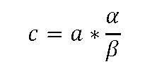

・STR-CEにはスタターピークが含まれており、1つの遺伝子座の中でピーク強度が1:20以上離れているピークはスタターピークとの区別が困難なため、1つの遺伝子座の中で1:20または1:40よりも強度比の大きいピークを分析しなくてもいい。
・劣化したDNAは、全体のDNA量も少なくなっている場合があるため、ピーク強度が1:20または1:40または1:100以上離れているピークを分析しなくてもいい。
・上記のように、極端にピーク間の強度比が大きくなるような電気泳動図では、小さいピークが有意でないため、分析対象となる最大のピーク強度に対する最小のピーク強度を規定するInter locus PHRの閾値が設定されていてもいい。図27を用いてmとnの間隔を設定する場合、分析対象とするアレルの存在比率はInter locus PHRの閾値よりもやや少なく設定することが好適である。
Partial profileも分析の対象とする場合、30~34サイクルが適切である。
DNA鑑定にて、PCRに投入されるDNAが1.5 μgを超えることはほぼないため、サイクル数を20よりも小さくしても、正しく検出できる遺伝子座の数が増えることはない。そのため、サイクル数は20以上に設定することが好適である。
図28(1)にmとnを設定した時の分析範囲拡大率を示す。本表に基づいて、必要な拡大率を得るためにmとnの間隔を決めてもよい。ただし、本表は、Stochastic effectなどのDNA濃度範囲に依存した分析範囲の変化を考慮していない。また、もとの分析範囲が拡大率よりも大きい場合、図24(2)のように分析できないDNA量範囲が生じてしまうため不適である。また、アレル間の存在比の差が大きいDNAを分析対象とする場合、もとの分析範囲に対してギリギリの拡大率を設定すると分析できないアレルが出てしまう。
図14のようにm回のサーマルサイクルが終わったのちにFinal extensionステップを行い分割し、n回のサーマルサイクルが終わったのちに再度Final extensionを行ってもいい。この場合には、たとえば、分析システム101は、PCR反応液mを50℃~80℃の範囲内の一定温度で1~20分保持し、その後に一部を取り出す。本構成の場合、PCR周りに必要なヒーターが1つで済むため、装置や流路デバイス構造がシンプルになる。
分割PCRでCEを2回以上行う場合、電気泳動図が2つ以上発生する。2つの電気泳動図またはDNA鑑定結果はどちらもユーザに提供してもいい。2つ以上の電気泳動図について、よりDNA鑑定に望ましいかどうかをスコアリングしてCE分析結果と併せて提供してもいい。
mの増幅産物を先に分析する場合、図30に示すようなフローチャートにのっとって増幅産物nを分析するかどうか決定してもいい。ただし、図30に示すフローチャートは1例で、ここにない判定基準や分岐条件が含まれていてもいい。例えば得られたピーク数、遺伝子座数、データがミックスかどうか、等に応じて判定基準が変化してもいい。また、図30に示されている判定基準が部分的にまたは全部省略されてもよく、または別の基準に置き換えられていてもいい。
nの増幅産物を先に分析する場合、図31に示すようなフローチャートにのっとって増幅産物mを分析するかどうか決定してもいい。ただし、図31に示すフローチャートは1例で、ここにない判定基準や分岐条件が含まれていてもいい。例えば得られたピーク数、遺伝子座数、データがミックスかどうか、等に応じて変化する判定基準が想定し得る。また、図31に示されている判定基準が部分的にまたは全部省略され、または別の基準に置き換えられていてもいい。
分析システム101には2つの異なるサイクル数、nとmがプリセットされていてもいい。mとnは先に述べたように、CE分析範囲やDNAの増幅可能量に応じて適切に設定されていることが好適である。
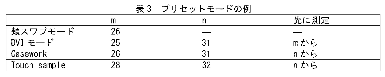
以上の実施形態では、mとnの分析を毎回両方行う場合と、mとnのどちらかのみを分析する回が存在する実施について述べた。
i)1つサンプルにつき、1本のキャピラリしか使えない場合
図32に分析システム101の動作タイミングについて典型例を示す。本動作タイミングは、まずステップ401にて1つ目のサンプルAが投入され、ステップ402~404にて前処理カートリッジでサンプルが処理され、ステップ405で泳動サンプルmまたはnがCEで分析される。
図33に分析システムの動作タイミングについて典型例を示す。
分析システム101には、1つの流路デバイス104と1つのCE部105が備えられている。
分析システム101には、1つの流路デバイス104と2つのCE部105が備えられている。
102 コンピュータ
103 データベース
104 流路デバイス
105 CE部
106 ユーザインターフェイス
201~207 判定基準
301 溶解チャンバ
302 精製膜
303 精製膜チャンバ
304 PCRチャンバ
305 廃液チャンバ
306 外部接続口
307 ポンプおよびバルブ
308 PCR試薬貯留部
309 PCR試薬
310 泳動試薬貯留部
311 泳動試薬
312~314 試薬貯留部
315 流路
316 流路
317 加熱部
318 加熱部
319 流路
320 分注チャンバ
321 待機部
322 流路
323~326 バルブ
327 混合チャンバ
328~330 流路
331 泳動試薬貯留部
332~334 空気貯留部
335 PCR反応液
336 泳動サンプル
337~339 バルブ
401 サンプル投入ステップ
402 溶解ステップ
403 精製ステップ
404 増幅ステップ
405 検出ステップ
701 液面
702 ベントフィルタ
703 流路
704 流路抵抗体
705 液面検知センサ
801 CEの検出上限またはPCRの増幅産物濃度上限
802 CEの検出下限
803 STR-CEの分析範囲
804 分割PCRによるSTR-CEの分析範囲
805,806 プロット
807 CEのダイナミックレンジ
Claims (17)
- サーマルサイクルを実施するPCRチャンバを有する流路デバイスと、
PCR反応液を電気泳動分析するキャピラリ電気泳動部と、
を有するDNA分析システムにおいて、
前記DNA分析システムは、
事前に設定されるmおよびnの値を記憶し、
前記PCRチャンバにおいて、PCR反応液に対しm回のサーマルサイクルを実施して第1反応液を生成し、
前記第1反応液の一部を、組成を変えずに前記PCRチャンバから取り出し、
前記第1反応液の前記一部を、前記キャピラリ電気泳動部において電気泳動分析し、
前記PCRチャンバにおいて、前記PCRチャンバに残された前記第1反応液に対し、サーマルサイクルの合計回数がn回となるように、n-m回(ただしn-mは2以上の整数)のサーマルサイクルを実施して第2反応液を生成し、
前記第2反応液の少なくとも一部を、組成を変えずに前記PCRチャンバから取り出し、
前記第2反応液の前記少なくとも一部を、前記キャピラリ電気泳動部において電気泳動分析する、
DNA分析システム。 - 請求項1において、mが20以上32以下であるDNA分析システム。
- 請求項1において、nが24以上36以下であるDNA分析システム。
- 請求項1において、nがmよりも4~9多いDNA分析システム。
- 請求項1において、前記DNA分析システムは、前記第1反応液の前記一部および前記第2反応液の前記少なくとも一部に対し、前記電気泳動分析の前に電気泳動分析以外の方法による分析を実行しない、DNA分析システム。
- 請求項1において、前記DNA分析システムは、前記第1反応液の前記一部および前記第2反応液の前記少なくとも一部の少なくとも一方を、複数種のDNA断片を含む溶液と混合する、DNA分析システム。
- 請求項1において、前記DNA分析システムは、前記第1反応液の前記一部および前記第2反応液の前記少なくとも一部の少なくとも一方を、電気泳動分析の前に、純水またはホルムアミドまたは10 mS/cm以下の導電率の溶液と混合して混合液を生成する、DNA分析システム。
- 請求項7において、前記DNA分析システムは前記混合液を90℃以上に加熱する、DNA分析システム。
- 請求項1において、前記流路デバイスはPCR反応液の調整から前記n-m回のサーマルサイクルまでを全自動で実施する、DNA分析システム。
- 請求項1において、
前記流路デバイスは計量部を有しており、
前記DNA分析システムは、前記m回のサーマルサイクルの終了後に、前記計量部に前記第1反応液を搬送することにより、0.1%~50%の範囲内の所定量の第1反応液を計量する、
DNA分析システム。 - 請求項1において、前記流路デバイスは開閉可能なバルブを有しており、前記m回のサーマルサイクルの開始前に前記バルブを閉じて、前記m回のサーマルサイクルの終了後に前記バルブを開放することにより、前記第1反応液の前記一部を分割して取り出す、DNA分析システム。
- 請求項1において、前記DNA分析システムは、前記第1反応液の前記一部を50℃~80℃の範囲内の一定温度で1~20分保持する、DNA分析システム。
- 請求項1において、前記DNA分析システムは、前記第1反応液を50℃~80℃の範囲内の一定温度で1~20分保持し、その後に前記一部を取り出す、DNA分析システム。
- 請求項1において、前記DNA分析システムは、n回のサーマルサイクル終了時に、PCRチャンバ内のPCR反応液を全量PCRチャンバの外に搬送するDNA分析システム。
- 請求項1において、
前記PCR反応液は、2以上のプライマセットを含み、
前記PCR反応液は、2以上の増幅遺伝子領域を含むDNAを含む、
DNA分析システム。 - 請求項1において、前記DNA分析システムは、
前記第1反応液の前記一部に対する前記電気泳動分析の結果と、前記第2反応液の前記少なくとも一部に対する前記電気泳動分析の結果とのうち、いずれがより良い結果であるかを判定し、
前記より良い結果を出力する、または、どちらが良い結果であるかを判定できる情報を出力する、
DNA分析システム。 - サーマルサイクルを実施するPCRチャンバを有する流路デバイスと、
PCR反応液を電気泳動分析するキャピラリ電気泳動部と、
を有するDNA分析システムにおいて、
前記DNA分析システムは、
事前に設定されるmおよびnの値を記憶し、
前記PCRチャンバにおいて、PCR反応液に対しm回のサーマルサイクルを実施して第1反応液を生成し、
前記第1反応液の一部を、組成を変えずに前記PCRチャンバから取り出し、
前記PCRチャンバにおいて、前記PCRチャンバに残された前記第1反応液に対し、サーマルサイクルの合計回数がn回となるように、n-m回(ただしn-mは2以上の整数)のサーマルサイクルを実施して第2反応液を生成し、
前記第2反応液の少なくとも一部を、組成を変えずに前記PCRチャンバから取り出し、
前記第1反応液の前記一部および前記第2反応液の前記少なくとも一部のうち一方を、前記キャピラリ電気泳動部において電気泳動分析し、
前記一方の電気泳動分析の結果に基づいて、前記第1反応液の前記一部または前記第2反応液の前記少なくとも一部のうち他方について電気泳動分析の実行を制御する、
DNA分析システム。
Priority Applications (5)
| Application Number | Priority Date | Filing Date | Title |
|---|---|---|---|
| DE112023005566.1T DE112023005566T5 (de) | 2023-07-03 | 2023-07-03 | Dna-analysesystem |
| CN202380094728.2A CN120752350A (zh) | 2023-07-03 | 2023-07-03 | Dna分析系统 |
| PCT/JP2023/024617 WO2025009019A1 (ja) | 2023-07-03 | 2023-07-03 | Dna分析システム |
| GB2514456.9A GB2644454A (en) | 2023-07-03 | 2023-07-03 | DNA analysis system |
| JP2025530818A JP7880015B2 (ja) | 2023-07-03 | 2023-07-03 | Dna分析システム |
Applications Claiming Priority (1)
| Application Number | Priority Date | Filing Date | Title |
|---|---|---|---|
| PCT/JP2023/024617 WO2025009019A1 (ja) | 2023-07-03 | 2023-07-03 | Dna分析システム |
Publications (1)
| Publication Number | Publication Date |
|---|---|
| WO2025009019A1 true WO2025009019A1 (ja) | 2025-01-09 |
Family
ID=94171715
Family Applications (1)
| Application Number | Title | Priority Date | Filing Date |
|---|---|---|---|
| PCT/JP2023/024617 Ceased WO2025009019A1 (ja) | 2023-07-03 | 2023-07-03 | Dna分析システム |
Country Status (5)
| Country | Link |
|---|---|
| JP (1) | JP7880015B2 (ja) |
| CN (1) | CN120752350A (ja) |
| DE (1) | DE112023005566T5 (ja) |
| GB (1) | GB2644454A (ja) |
| WO (1) | WO2025009019A1 (ja) |
Citations (4)
| Publication number | Priority date | Publication date | Assignee | Title |
|---|---|---|---|---|
| JP2006507849A (ja) * | 2002-11-21 | 2006-03-09 | プリメラ バイオシステムズ | 増幅反応分析のためのサンプリング方法および装置 |
| JP2006519611A (ja) * | 2003-03-12 | 2006-08-31 | プライメラ バイオシステムズ インコーポレイテッド | リアルタイム遺伝子発現プロフィール解析 |
| US20060269932A1 (en) * | 2004-12-15 | 2006-11-30 | Primera Biosystems, Inc. | Compositions and methods for polynucleotide amplification and detection |
| JP2017077180A (ja) * | 2014-01-27 | 2017-04-27 | 株式会社日立ハイテクノロジーズ | 核酸分析装置 |
Family Cites Families (7)
| Publication number | Priority date | Publication date | Assignee | Title |
|---|---|---|---|---|
| US7445893B2 (en) | 2002-04-12 | 2008-11-04 | Primera Biosystems, Inc. | Sampling method for amplification reaction analysis |
| DE102006027675B4 (de) | 2006-06-14 | 2011-05-12 | Siemens Ag | Verfahren zur Bestimmung der Konzentration von Nukleinsäuren |
| JP5494480B2 (ja) | 2007-06-11 | 2014-05-14 | 和光純薬工業株式会社 | 集積リアルタイムce検出を用いるマイクロチップ大容量pcr |
| EP4124856A1 (en) | 2010-03-09 | 2023-02-01 | ANDE Corporation | Biochip with valve |
| US10233491B2 (en) | 2015-06-19 | 2019-03-19 | IntegenX, Inc. | Valved cartridge and system |
| CA3069668A1 (en) | 2017-07-12 | 2019-01-17 | Ande Corporation | Pattern recognition system |
| CN116769579A (zh) | 2018-12-04 | 2023-09-19 | 尹特根埃克斯有限公司 | 控制用于str分析的dna浓度 |
-
2023
- 2023-07-03 WO PCT/JP2023/024617 patent/WO2025009019A1/ja not_active Ceased
- 2023-07-03 JP JP2025530818A patent/JP7880015B2/ja active Active
- 2023-07-03 GB GB2514456.9A patent/GB2644454A/en active Pending
- 2023-07-03 DE DE112023005566.1T patent/DE112023005566T5/de active Pending
- 2023-07-03 CN CN202380094728.2A patent/CN120752350A/zh active Pending
Patent Citations (4)
| Publication number | Priority date | Publication date | Assignee | Title |
|---|---|---|---|---|
| JP2006507849A (ja) * | 2002-11-21 | 2006-03-09 | プリメラ バイオシステムズ | 増幅反応分析のためのサンプリング方法および装置 |
| JP2006519611A (ja) * | 2003-03-12 | 2006-08-31 | プライメラ バイオシステムズ インコーポレイテッド | リアルタイム遺伝子発現プロフィール解析 |
| US20060269932A1 (en) * | 2004-12-15 | 2006-11-30 | Primera Biosystems, Inc. | Compositions and methods for polynucleotide amplification and detection |
| JP2017077180A (ja) * | 2014-01-27 | 2017-04-27 | 株式会社日立ハイテクノロジーズ | 核酸分析装置 |
Also Published As
| Publication number | Publication date |
|---|---|
| CN120752350A (zh) | 2025-10-03 |
| JP7880015B2 (ja) | 2026-06-24 |
| GB2644454A (en) | 2026-04-15 |
| DE112023005566T5 (de) | 2026-04-16 |
| JPWO2025009019A1 (ja) | 2025-01-09 |
Similar Documents
| Publication | Publication Date | Title |
|---|---|---|
| US8759079B2 (en) | Device for automatically analyzing nucleic acid | |
| EP1192007B1 (de) | Microchip-matrix-vorrichtung zur vervielfältigung und charakterisierung von nukleinsäuren | |
| US20140256029A1 (en) | Apparatus for polynucleotide detection and quantitation | |
| JP2018520706A (ja) | 試料採取からngsライブラリ調製までの自動化 | |
| JP2015042182A (ja) | 核酸検出方法 | |
| JP2017045451A (ja) | βグロビン遺伝子の変異を検出するためのマイクロアレイ及びその検出方法 | |
| Grieco et al. | Protocol to analyze circulating small non-coding RNAs by high-throughput RNA sequencing from human plasma samples | |
| Bannai et al. | Single-nucleotide-polymorphism genotyping for whole-genome-amplified samples using automated fluorescence correlation spectroscopy | |
| CN108138366A (zh) | 优化的临床样品测序 | |
| US6518027B2 (en) | Sample preparation method and a sample preparation apparatus for DNA analysis | |
| Schrijver et al. | Diagnostic Single Nucleotide Polymorphism Analysis of Factor V Leiden and Prothrombin 20210G> A: A Comparison of the Nanogen Electronic Microarray With Restriction Enzyme Digestion and the Roche LightCycler | |
| CN109371132A (zh) | 一种用于检测cyp2d6基因拷贝数变异的试剂盒 | |
| KR101829668B1 (ko) | 생체분자와 단일가닥핵산의 결합정보를 생성하기 위한 기준물질 및 핵산칩, 이들의 제조방법 및 이들을 이용한 생체분자 분석방법 및 장치 | |
| KR20050075436A (ko) | 증폭 반응 분석을 위한 샘플링 방법과 장치 | |
| CN111471588A (zh) | 一种实时荧光定量pcr仪模块 | |
| GB2644454A (en) | DNA analysis system | |
| KR20210145972A (ko) | 크리스퍼 진단법을 이용한 디지털 검출 방법 및 이의 장치 | |
| JP2008306949A (ja) | 塩基配列の増幅方法 | |
| WO2016120970A1 (ja) | 核酸分離方法、及び装置 | |
| Sheth | Analyzing and interpreting deoxyribonucleic acid from multiple donors using a forensically relevant single-cell strategy | |
| EP4608557A1 (en) | A fluidic device and methods for characterization of an infection or other condition | |
| CN121992088A (zh) | 基于数字微流控的单细胞数字pcr及其应用 | |
| Bonetta | Microarrays: branching out from expression analysis | |
| JP2009517074A (ja) | 核酸配列変化の検出 | |
| JP2003315329A (ja) | 遺伝子検出方法及び遺伝子検出装置 |
Legal Events
| Date | Code | Title | Description |
|---|---|---|---|
| 121 | Ep: the epo has been informed by wipo that ep was designated in this application |
Ref document number: 23942635 Country of ref document: EP Kind code of ref document: A1 |
|
| ENP | Entry into the national phase |
Ref document number: 2025530818 Country of ref document: JP Kind code of ref document: A |
|
| WWE | Wipo information: entry into national phase |
Ref document number: 2025530818 Country of ref document: JP |
|
| WWE | Wipo information: entry into national phase |
Ref document number: 202380094728.2 Country of ref document: CN |
|
| ENP | Entry into the national phase |
Ref document number: 202514456 Country of ref document: GB Kind code of ref document: A Free format text: PCT FILING DATE = 20230703 |
|
| WWE | Wipo information: entry into national phase |
Ref document number: 2514456.9 Country of ref document: GB |
|
| WWE | Wipo information: entry into national phase |
Ref document number: 112023005566 Country of ref document: DE |
|
| WWP | Wipo information: published in national office |
Ref document number: 202380094728.2 Country of ref document: CN |
|
| WWE | Wipo information: entry into national phase |
Ref document number: 11202505601W Country of ref document: SG |
|
| WWP | Wipo information: published in national office |
Ref document number: 11202505601W Country of ref document: SG |
|
| WWP | Wipo information: published in national office |
Ref document number: 112023005566 Country of ref document: DE |
|
| 122 | Ep: pct application non-entry in european phase |
Ref document number: 23942635 Country of ref document: EP Kind code of ref document: A1 |