WO2025009014A1 - 巻上機、及び、エレベーター - Google Patents
巻上機、及び、エレベーター Download PDFInfo
- Publication number
- WO2025009014A1 WO2025009014A1 PCT/JP2023/024606 JP2023024606W WO2025009014A1 WO 2025009014 A1 WO2025009014 A1 WO 2025009014A1 JP 2023024606 W JP2023024606 W JP 2023024606W WO 2025009014 A1 WO2025009014 A1 WO 2025009014A1
- Authority
- WO
- WIPO (PCT)
- Prior art keywords
- encoder
- shaft
- bolt
- recess
- hole
- Prior art date
- Legal status (The legal status is an assumption and is not a legal conclusion. Google has not performed a legal analysis and makes no representation as to the accuracy of the status listed.)
- Ceased
Links
Images




Classifications
-
- B—PERFORMING OPERATIONS; TRANSPORTING
- B66—HOISTING; LIFTING; HAULING
- B66B—ELEVATORS; ESCALATORS OR MOVING WALKWAYS
- B66B11/00—Main component parts of lifts in, or associated with, buildings or other structures
- B66B11/04—Driving gear ; Details thereof, e.g. seals
- B66B11/08—Driving gear ; Details thereof, e.g. seals with hoisting rope or cable operated by frictional engagement with a winding drum or sheave
Definitions
- the present invention relates to a hoist and an elevator.
- An elevator is equipped with a car that is placed in the hoistway and a hoist that raises and lowers the car.
- the encoder for machine-room-less elevator hoists has been made thinner by placing the encoder inside the rotor.
- Patent Document 1 discloses a configuration in which an encoder is fixed inside the main shaft, which serves as the rotating shaft, in a hoist.
- Patent Document 1 discloses a configuration in which, when connecting an encoder shaft that rotates with the rotor to an encoder installed inside the main shaft, a fixing bolt is inserted from the encoder side to fix the encoder and the encoder shaft.
- the present invention provides a hoist and elevator that allows easy removal and installation of the encoder during inspection.
- the hoist of the present invention comprises a frame on which a stator is provided, a main shaft supported by the frame, a sheave supported rotatably on the main shaft and around which a main rope is wound, a rotor having a rotor facing the stator, an encoder installed in the space inside the main shaft, and an encoder shaft fixed to the rotor and connected to the encoder.
- the encoder shaft and the encoder are connected by a fixing bolt that passes through a through hole and can be screwed into a bolt hole provided in the encoder.
- the elevator of the present invention comprises a car, a counterweight connected to the car via a main rope, and a hoist around which the main rope is wound, the hoist having the above-mentioned configuration.
- the present invention makes it easy to remove and install the encoder during inspection.
- FIG. 1 is a schematic diagram of an elevator 1 according to one embodiment of the present invention.
- 1 is a cross-sectional configuration diagram of a hoist 100 according to one embodiment of the present invention.
- FIG. 2 is an enlarged cross-sectional view of a main part of the hoisting machine.
- 1 is a schematic diagram of an encoder 10 according to the present embodiment in the state where an encoder shaft 11 is being removed.
- FIG. FIG. 2 is a schematic diagram of the configuration of the encoder 10 of the present embodiment after the encoder shaft 11 has been removed.
- FIG. 4 is a schematic cross-sectional configuration diagram of a main part of a hoist according to a comparative example.
- 11 is a schematic diagram of an encoder 200 according to a comparative example in which an encoder shaft 111 is being removed.
- FIG. FIG. 11 is a schematic diagram of the configuration of the encoder 200 according to the comparative example after the encoder shaft 111 has been removed.
- Configuration of the Elevator Fig. 1 is a schematic configuration diagram of an elevator 1 according to one embodiment of the present invention (hereinafter, referred to as this embodiment).
- an elevator 1 using the so-called 2:1 roping system will be described as an example.
- the elevator of the present invention is not limited to elevators using the 2:1 roping system, but can also be applied to elevators using the 1:1 roping system.
- the elevator 1 has a car 120 that ascends and descends in the elevator shaft, a main rope 130, a hoist 100, and a counterweight 140 that is suspended from the car 120 via the main rope 130.
- the direction in which the car 120 and counterweight 140 ascend and descend is referred to as the up and down direction.
- the car 120 carries passengers and luggage.
- Under-car pulleys 160A and 160B are provided at the bottom of the car 120 in the vertical direction.
- a main rope 130 is wound around the under-car pulleys 4160A and 160B.
- a weight side pulley 150 is provided on the counterweight 140.
- a main rope 30 is wound around the weight side pulley 150.
- the hoist 100 is installed at the top of the elevator shaft.
- the hoist 100 also has a sheave 3 (see Figure 2) around which the main rope 130 is wound.
- the hoist 100 raises and lowers the car 120 and counterweight 140 in a bucket-like manner via the main rope 130.
- One end of the main rope 130 is attached to the top of the hoistway.
- the main rope 120 extends from the top of the hoistway towards the under-car pulleys 160A and 160B.
- the main rope 130 is then wound from one end around the under-car pulleys 160A and 160B, the sheave 3 of the hoisting machine 100, and the weight-side pulley 150, in that order.
- the other end of the main rope 130 which extends from the weight-side pulley 150 toward the top of the hoistway, is attached to the top of the hoistway, just like the one end.
- the hoist 100 has a frame 2, a main shaft 7, a rotor 4 rotatably supported on the main shaft 7, and a brake mechanism (not shown) that brakes the rotation of the rotor 4.
- the hoist 100 also has a bearing 8 attached to the outer periphery of the main shaft 7 to rotatably support the rotor 4 on the main shaft 7.
- the hoist 100 is an outer rotor type hoist that includes a stator 5 attached to the frame 2 and a rotor 6 attached to the rotor 4 so as to be positioned outside the stator 5.
- the hoist 100 also has an encoder 10 arranged inside the main shaft 7, and an encoder shaft 11 that connects the encoder 10 to the rotor 4.
- the axial direction of the main shaft 7 is defined as the X direction.
- the direction perpendicular to the axial direction of the main shaft 7, in which the car 120 rises and falls, is defined as the Y direction.
- the direction perpendicular to the X and Y directions is defined as the Z direction.
- the frame 2 and the rotating body 4 face each other in the X direction.
- the rotating body 4 side is defined as one side.
- the frame 2 side is defined as the other side.
- the frame 2 has a shaft fixing portion 23 to which the main shaft 7 is fixed, an outer wall portion 21 , and a connection portion 22 that connects the shaft fixing portion 23 and the outer wall portion 21 .
- the shaft fixing part 23 is located approximately in the center of the frame 2 on the YZ plane.
- the shaft fixing part 23 is formed in a cylindrical shape with its axial direction aligned in the X direction.
- the main shaft 7 is fixed to the inner peripheral surface of the shaft fixing part 23, and the stator 5 is attached to the outer peripheral surface.
- the outer wall portion 21 is formed in a cylindrical shape with its axial direction in the X direction.
- the outer wall portion 21 is located radially outside the shaft fixing portion 23.
- the inner periphery of the outer wall portion 21 and the outer periphery of the shaft fixing portion 23 face each other at a predetermined distance in the radial direction.
- the stator 5 and rotor 6 are arranged in the space between the outer wall portion 21 and the shaft fixing portion 23.
- connection part 22 is made of a circular plate.
- the plane of the connection part 22 is approximately perpendicular to the X direction.
- the inside of the connection part 22 is continuous with the other end of the shaft fixing part 23 in the X direction.
- the outside of the connection part 22 is continuous with the other end of the outer wall part 21 in the X direction.
- the main shaft 7 is formed in a cylindrical shape with its axial direction in the X direction.
- the other side of the main shaft 7 in the X direction is fitted into the inner peripheral surface of a shaft fixing portion 23 of the frame 2.
- the main shaft 7 is fixed to the shaft fixing portion 23.
- One side of the main shaft 7 in the X direction protrudes from the shaft fixing portion 23.
- One side of the main shaft 7 in the X direction supports the rotor 4 via a bearing 8 so as to be rotatable about its axis.
- An encoder chamber 9 is provided inside the cylindrical hole of the spindle 7.
- the encoder chamber 9 opens to one end face of the spindle 7 in the X direction.
- the encoder chamber 9 houses an encoder 10, which is a rotation detector.
- the encoder 10 has a connecting portion 14 (see FIG. 3) that protrudes from one end surface in the X direction.
- the connecting portion 14 is made of a cylindrical member into which a shaft portion 13 of the encoder shaft 11 (described later) can be inserted, and serves as a connecting portion of the encoder shaft 11 (described later).
- the encoder 10 is fixed to the main shaft 7 by a support body (not shown). The configuration of the encoder 10 will be described in detail later.
- a bearing 8 is attached to the outer periphery of one side in the X direction of the main shaft 7.
- the bearing 8 is formed in an annular shape, and the end on the other side in the X direction abuts against a positioning step (not shown) of the main shaft 7, thereby positioning the bearing 8.
- the bearing 8 is composed of, for example, a ball bearing or a roller bearing.
- a bearing cover that suppresses movement of the bearing 8 is attached to the end on one side in the X direction of the main shaft 7.
- the inner circumferential surface of the bearing 8 contacts the main shaft 7 with a predetermined pressure, and the outer circumferential surface contacts the rotating body 4 with a predetermined pressure. In this way, the bearing 8 supports the rotating body 4 so that it can rotate relative to the main shaft 7.
- the rotating body 4 is a member that rotatably fits into the bearing 8.
- the rotating body 4 has a first cylindrical portion 41 that holds the bearing 8 between itself and the main shaft 7, a second cylindrical portion 43 to which the rotor 6 is attached, and a connecting portion 42 that connects the first cylindrical portion 41 and the second cylindrical portion 43.
- the first cylindrical portion 41 is formed into a cylindrical shape with its axial direction aligned in the X direction.
- the second cylindrical portion 43 is formed into a cylindrical shape with its axial direction aligned in the X direction.
- the second cylindrical portion 43 is formed into a cylindrical shape with a larger diameter than the first cylindrical portion 41.
- the inner periphery of the first cylindrical portion 41 contacts the bearing 8 with a predetermined pressure.
- the first cylindrical portion 41 is provided so as to protrude to one side in the X direction beyond the second cylindrical portion 43 and the connection portion 42.
- the sheave 3 is attached to the outer periphery of the protruding first cylindrical portion 41.
- the second cylindrical portion 43 is disposed in the space between the outer wall portion 21 of the frame 2 and the shaft fixing portion 23.
- the rotor 6 is attached to the inner periphery of the second cylindrical portion 43.
- connection portion 42 is made of a circular plate.
- the plane of the connection portion 42 is approximately perpendicular to the X direction.
- One end face of the connection portion 42 in the X direction is continuous with the end of the first tubular portion 41 on the other side in the X direction.
- the other end face of the connection portion 42 in the X direction is continuous with the end of the second tubular portion 43 on one side in the X direction.
- the second tubular portion 43 is located on the other side in the X axis direction than the first tubular portion 41.
- the sheave 3 is formed in a cylindrical shape with its axial direction being in the X direction.
- the sheave 3 is attached to the outer circumferential surface of the first tubular portion 41 by shrink fitting or the like.
- a plurality of grooves 3a around which the main ropes 130 are wound are formed on the outer circumferential portion of the sheave 3.
- the main ropes 130 (not shown) are wound around the plurality of grooves 3a.
- the encoder shaft 11 has a cover portion 18 and a shaft portion 13. As shown in Fig. 3, the cover portion 18 is formed in a disk shape. The cover portion 18 is fitted into a step portion provided at one end in the X direction of the first cylindrical portion 41 of the rotating body 4, and covers an opening at one end in the X direction of the first cylindrical portion 41. The outer diameter of the cover portion 18 is smaller than the outer diameter of the first cylindrical portion 41.
- the shaft portion 13 of the encoder shaft 11 is a convex member provided on the other side of the cover portion 18 in the X direction.
- the shaft portion 13 is fitted into a recess 50 (see FIG. 3) of the encoder 10, which will be described later.
- the encoder shaft 11 is fixed to the encoder 10 by a fixing bolt 12 that is inserted from the encoder shaft 11 to the encoder 10 side.
- connection configuration between the shaft portion 13 of the encoder shaft 11 and the connection portion 14 of the encoder 10 will be described in detail later.
- the encoder shaft 11 is connected to the encoder 10, so that the rotation of the rotating body 4 is transmitted to the encoder 10 via the encoder shaft 11. As a result, the rotation of the rotating body 4 is detected by the encoder 10.
- the stator 5 is attached to the outer periphery of the shaft fixing portion 23 of the frame 2.
- the stator 5 is composed of an iron core and a coil wound around the iron core.
- the rotor 6 is attached to the inner periphery of the second cylindrical portion 43 of the rotor 4.
- the rotor 6 is formed in a cylindrical shape with its axial direction aligned with the X direction.
- the rotor 6 is made of a magnetic material.
- the rotor 6 faces the stator 5 across an air gap in the radial direction of the shaft fixing portion 23 and the second cylindrical portion 43.
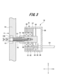
- Fig. 3 is an enlarged view of a portion of the hoisting machine 100 including the encoder 10.
- the encoder 10 is composed of a cover portion 31, a connecting portion 14, a connecting portion support body 32, a slit disk 33, a light emitting portion 34, a light receiving portion 35, and a substrate 36.
- the cover section 31 is composed of a cylindrical cover body 37 with its axial direction in the X direction, and a disk-shaped bottom section 38 provided to cover the open end of the cover body 37 on the other side of the cover body 37 in the X direction.
- a slit disk 33 for detecting rotation Inside the cover body 37, a slit disk 33 for detecting rotation, a light emitter 34, a light receiver 35, and a substrate 36 are arranged inside the cover body 37.
- the bottom section 38 is provided with a hole (not shown) through which a wiring 53 connected to the substrate 36 is inserted.
- the connecting part support 32 is a member that supports the connecting part 14 on one side of the cover part 31 in the X direction.
- the connecting part support 32 is composed of a cylindrical member with the axial direction being the X direction, and the outer peripheral surface is fixed to the inner peripheral surface of the cover body 37, while the inner peripheral surface rotatably supports the connecting part 14 via a bearing 39.
- the connecting part 14 is composed of a cylindrical member whose axial direction is in the X direction, and is rotatably supported on the cover part 31 by the connecting part support body 32.
- the connecting part 14 is arranged so that one side in the X direction protrudes from the connecting part support body 32, and the other side in the X direction protrudes into the space between the connecting part support body 32 and the bottom part 38.
- the connecting portion 14 is provided with a recess 50 formed to a predetermined depth from one end of the X-direction to the other side, and a bolt hole 51 formed continuous with the recess 50 to the other side in the X-direction.
- the recess 50 is a groove into which the shaft portion 13 of the encoder shaft 11 fits.
- the recess 50 is formed in a tapered shape such that the inner diameter becomes smaller from one side to the other side in the X-direction. The tapered surface of the shaft portion 13 of the encoder shaft 11 fits closely into the recess 50.
- the bolt hole 51 is a bolt hole into which the fixing bolt 12 described later screws, and has a female thread (threaded portion) on its inner circumferential surface.
- the inner diameter W1 of the bolt hole 51 is smaller than the diameter of the other end of the recess 50 in the X direction. Therefore, a step 56 is formed at the boundary between the recess 50 and the bolt hole 51. This step 56 serves as a stopper for the removal bolt 16 described later.
- the slit disk 33 is a slit-shaped disk.
- the slit disk 33 is attached to the outer peripheral surface of the connecting part 14 that protrudes between the bottom 38 of the cover part 31 and the other surface of the connecting part support 32 in the X direction.
- the slit disk 33 rotates in response to the rotation of the connecting part 14.
- the light emitting unit 34 is composed of a light emitting element.
- the light emitting unit 34 is fixed to the connecting part support body 32 so that light is irradiated towards the slit disk 33.
- the light receiving unit 35 is provided at a position facing the light emitting unit 34 across the slit disk 33 in the X direction.
- the substrate 36 detects the light received by the light receiving unit 35.
- the light receiving unit detects the transmission/blocking of light caused by the rotation of the slit disk 33, making it possible to detect the rotation speed of the rotating body.
- a wiring 53 is connected to the substrate 36, and this wiring 53 is drawn out from the bottom 38 of the cover part 31 to the outside of the encoder 10.
- the encoder shaft 11 is composed of a disk-shaped cover portion 18 and a shaft portion 13.
- the shaft portion 13 is a convex (cylindrical) member protruding in a substantially vertical direction from the center of the cover portion 18, and its outer diameter is tapered so that it gradually becomes thinner from one side to the other side in the X direction.
- the shaft portion 13 is inserted into the encoder chamber 9 in the main shaft 7 and is connected to a connecting portion 14 of the encoder 10 arranged in the encoder chamber 9.
- a through hole 19 is provided from one end of the encoder shaft 11 in the X direction to the other end of the shaft portion 13 in the X direction.
- the through hole 19 is formed so that a fixing bolt 12 for mounting and a removal bolt 16 (see FIG. 5), which will be described later, can be inserted therethrough.
- the fixing bolt 12 is inserted from one side of the encoder shaft 11 in the X direction and fixed to the encoder 10, thereby connecting the encoder shaft 11 and the encoder 10.
- the inner diameter W2 of the through hole 19 is larger than the inner diameter of the bolt hole 51 provided in the connecting portion 14 of the encoder 10.
- the inner peripheral surface of the through hole 19 is formed with a female thread into which the male thread of the removal bolt 16 described later can be screwed.
- a recess 159 communicating with the through hole 19 is formed on one side of the cover portion 18 in the X direction.
- the recess 159 is recessed to a predetermined depth from one surface of the one side of the cover portion 18 in the X direction.
- This recess 159 is configured with a diameter capable of accommodating the head of the fixing bolt 12.
- the connecting part 14 rotates in conjunction with the rotation of the encoder shaft 11, and this rotation speed is detected.
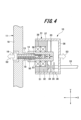
- Fig. 4 is a schematic diagram of the encoder 10 during removal of the encoder shaft 11
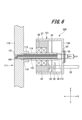
- Fig. 5 is a schematic diagram of the encoder 10 after the encoder shaft 11 has been removed.
- the fixing bolt 12 shown in FIG. 3 is removed, and then the removal bolt 16 shown in FIG. 4 is inserted into the through hole 19 from one side of the encoder shaft 11 in the X direction.
- the outer diameter W4 of the removal bolt 16 is larger than the outer diameter W3 of the fixing bolt 12, and is configured to have a diameter that can be screwed into the through hole 19 provided in the encoder shaft 11. Therefore, the removal bolt 16 is inserted while being screwed into the through hole 19 of the encoder shaft 11.
- the diameter W1 of the bolt hole 51 formed in the connecting portion 14 is smaller than the inner diameter W2 of the through hole 19. Therefore, after the removal bolt 16 reaches the other end of the recess 50 in the X direction, the removal bolt 16 abuts against the step 56 at the boundary between the recess 50 and the bolt hole 51. Therefore, the removal bolt 16 does not move any further to the other side in the X direction (arrow 1 in FIG. 4). Therefore, when the removal bolt 16 is rotated while abutting against the step 56, the encoder shaft 11 moves in the direction of coming out of the connecting portion 14, as shown by arrows S2 and S3 in FIG. 4.
- the encoder shaft 11 and the encoder 10 can be connected by inserting the fixing bolt 12 from the encoder shaft 11 side. Furthermore, in this embodiment, the encoder shaft 11 can be removed from the encoder 10 by inserting the removal bolt 16 from the encoder shaft 11 side.
- the encoder shaft 11 can be removed from the encoder 10 while the encoder 10 is held inside the main shaft 7. This makes it easier to install and remove the encoder 10.
- the shaft portion 13 of the encoder shaft 11 and the recess 50 into which the shaft portion 13 fits are tapered, but this is not limited to the above. By making them tapered as in this embodiment, the connecting force between the encoder shaft 11 and the encoder 10 at the connecting portion 14 can be increased. Furthermore, in this embodiment, the shaft portion 13 is fitted into the recess 50 of the connecting portion 14, but a recess may be provided on the shaft portion 13 side, and the connecting portion 14 of the encoder 10 may be fitted into the recess.
- the same effect as in this embodiment can be obtained by forming a through hole on the encoder shaft 11 side through which the fixing bolt 12 can pass, and forming a bolt hole 51 into which the fixing bolt 12 can be screwed in the connecting portion 14 of the encoder 10.
- FIG. 6 is a schematic cross-sectional configuration diagram of a main part of a hoist according to a comparative example.
- a fixing bolt 112 is inserted from the other side in the X direction of the encoder 200, and an encoder shaft 111 is attached to the encoder 200.
- parts corresponding to those in Fig. 3 are given the same reference numerals, and duplicated explanations will be omitted.
- the encoder 200 has a connecting portion 114, a cover portion 131, a connecting portion support 32, a slit disk 33 housed inside the cover portion 131, a light emitting portion 34, a light receiving portion 35, and a substrate 36.
- the connecting part support 32 is a member that supports the connecting part 114 on one side of the cover part 131 in the X direction.
- the connecting part support 32 is composed of a cylindrical member whose axial direction is the X direction, and its outer peripheral surface is fixed to the inner peripheral surface of the cover body 37.
- the inner peripheral surface of the connecting part support 32 rotatably supports the connecting part 114 via a bearing 39.
- the connecting part 114 is composed of a cylindrical member with its axial direction in the X direction, and like the encoder 10 of this embodiment, is rotatably supported on the cover part 131 by the connecting part support body 32.
- One side of the connecting part 114 in the X direction is provided so as to protrude from the connecting part support body 32, and the other side in the X direction is provided so as to protrude into the space between the connecting part support body 32 and the bottom part 138.
- the connecting portion 114 has a through hole 151 that passes through from the other end in the X direction to one side.
- the through hole 151 is a bolt hole into which a removal bolt 116, which will be described later, screws, and has a female thread on its inner circumferential surface.
- an opening 54 is provided in the bottom 138 of the cover portion 131 of the encoder 200 at a position opposite the connecting portion 114.
- the opening 54 is closed by a seal portion 55.
- the opening 54 serves as a work window when installing and removing the encoder 200.
- the encoder shaft 111 has a cover portion 118 and a shaft portion 113.
- the shaft portion 113 of the encoder shaft 111 is provided on the other side of the cover portion 118 in the X direction.
- the shaft portion 113 is a cylindrical member protruding in an approximately vertical direction from the center of the cover portion 118.
- the encoder shaft 111 is provided with a recess 119 into which the connecting portion 114 of the encoder 200 is fitted, spanning from the other side to one side of the shaft portion 113 in the X direction, and a bolt hole 121 formed continuous with the recess 119 and spanning one side in the X direction.
- the inner diameter W11 of the bolt hole 121 is smaller than the inner diameter W10 of the through hole 151 of the connecting portion 114, and the inner peripheral surface is provided with a female thread into which the mounting fixing bolt 112 screws.
- the inner diameter of the bolt hole 121 is formed smaller than the inner diameter of the end of one side in the X direction of the recess 119.
- a step 156 is formed at the boundary between the recess 119 and the bolt hole 121.
- the fixing bolt 112 is inserted from the other side of the encoder 200 in the X direction and screwed into the bolt hole 121 of the encoder shaft 111. This fixes the encoder 200 and the encoder shaft 111.
- Figure 7 is a schematic diagram of the configuration during removal of the encoder shaft 111 from the encoder 200
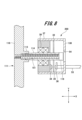
- Figure 8 is a schematic diagram of the configuration after the encoder shaft 111 has been removed from the encoder 200.
- the fixing bolt 12 can be attached and the removal bolt 16 can be inserted from the encoder shaft 11 side.
- the hoist 100 of this embodiment when removing the encoder shaft 11 from the encoder 10 or attaching it, there is no need to open the bottom 38 on the side where the substrate 36 of the encoder 10 is located. This prevents foreign matter from entering the inside of the encoder 10 and prevents malfunctions from occurring.
Landscapes
- Engineering & Computer Science (AREA)
- Civil Engineering (AREA)
- Mechanical Engineering (AREA)
- Structural Engineering (AREA)
- Transmission And Conversion Of Sensor Element Output (AREA)
Abstract
主軸内部の空間に設置されるエンコーダと、回転体に固定されると共に、エンコーダに連結されるエンコーダ軸とを備える。エンコーダ軸とエンコーダは、エンコーダ軸を貫通する貫通孔を貫通し、エンコーダに設けられたボルト穴に螺合可能な固定用ボルトによって連結される。
Description
本発明は、巻上機、及び、エレベーターに関する。
エレベーターは、昇降路内に配置される乗りかごと、乗りかごを昇降させる巻上機とを備えている。従来、機械室レスエレ用巻上機のエンコーダはロータ内部にエンコーダを設けることにより薄型化を図ってきた。
特許文献1では、巻上機において、回転軸となる主軸の内部にエンコーダを固定する構成が開示されている。特許文献1では、回転子の回転と共に回転するエンコーダ軸と、主軸の内部に設置されたエンコーダとを連結する際に、エンコーダ側から固定用ボルトを挿通し、エンコーダとエンコーダ軸とを固定する構成が開示されている。
ところで、巻上機のメンテナンス時において、エンコーダの交換作業を行う場合、エンコーダ軸とエンコーダとのボルト締結を解除する必要がある。巻上機において、正面側であるエンコーダ軸側(綱車側)から取り外し作業を行う場合には、エンコーダ側から挿通された固定用ボルトを取り外すため、一旦、エンコーダ軸とエンコーダとが固定された状態で主軸から引っ張り出さなければならない。
したがってエンコーダ軸側から固定用ボルトにてエンコーダ軸に締結する構造では、エンコーダの交換時における作業性が悪かった。
そこで、本発明は、点検時におけるエンコーダの取り外し及び取り付けが容易な巻上機、及び、エレベーターを提供する
上記課題を解決し、本発明の目的を達成するため、本発明の巻上機は、固定子が設けられたフレームと、フレームに支持された主軸と、主軸に回転可能に支持され、主ロープが巻回される綱車と、固定子に対向する回転子を有する回転体と、主軸内部の空間に設置されるエンコーダと、回転体に固定されると共に、エンコーダに連結されるエンコーダ軸とを備える。記エンコーダ軸とエンコーダは、貫通孔を貫通し、エンコーダに設けられたボルト穴に螺合可能な固定用ボルトによって連結される。
本発明のエレベーターは、乗りかごと、乗りかごと主ロープを介して連結される釣合おもりと、主ロープが巻き掛けられる巻上機を備え、巻上機は、上述の構成を有する。
本発明によれば、点検時におけるエンコーダの取り外し及び取り付けが容易となる。
以下、本発明の実施形態に係る巻上機、エレベーター、及び、巻上機の点検方法の一例を、図面を参照しながら説明する。なお、本発明は以下の例に限定されるものではない。以下で説明する各図において、共通の部材には同一の符号を付している。
1.エレベーターの構成
図1は、本発明の一実施形態(以下、本実施形態と記す)に係るエレベーター1の概略構成図である。
図1は、本発明の一実施形態(以下、本実施形態と記す)に係るエレベーター1の概略構成図である。
本実施形態では、図1に示すように、いわゆる2:1ローピング方式のエレベーター1を例に説明する。なお、本発明のエレベーターは、2:1ローピング方式のエレベーターに限定されるものではなく、1:1ローピング方式のエレベーターにも適用できるものである。
図1に示すように、エレベーター1は、昇降路内を昇降する乗りかご120と、主ロープ130と、巻上機100と、主ロープ130を介して乗りかご120に懸架される釣合おもり140とを有している。以下、乗りかご120及び釣合おもり140が昇降移動する方向を上下方向とする。
乗りかご120には、人や荷物を載せる。乗りかご120の上下方向の下部にはかご下プーリ160A、160Bが設けられている。かご下プーリ4160A、160Bには、主ロープ130が巻き掛けられている。釣合おもり140には、おもり側プーリ150が設けられている。おもり側プーリ150には、主ロープ30が巻き掛けられている。
巻上機100は、昇降路の最上部に設置されている。また、巻上機100には、主ロープ130が巻き掛けられる綱車3(図2参照)を有している。そして、巻上機100には、主ロープ130を介して乗りかご120及び釣合おもり140をつるべ式に昇降させる。
主ロープ130の一端部は、昇降路の上部に取り付けられている。主ロープ120は、昇降路の上部からかご下プーリ160A、160Bに向けて延在している。そして、主ロープ130は、一端部から、かご下プーリ160A、160B、巻上機100の綱車3、おもり側プーリ150の順に巻き掛けられる。
また、主ロープ130におけるおもり側プーリ150から昇降路の上方に向けて延在する他端部は、一端部と同様に、昇降路の上部に取り付けられる。巻上機100が駆動することで、乗りかご120及び釣合おもり140が昇降路内を昇降移動する。
2.巻上機
次に、巻上機100の構成について説明する。図2は、巻上機100の概略断面構成図である。
次に、巻上機100の構成について説明する。図2は、巻上機100の概略断面構成図である。
図2に示すように、巻上機100は、フレーム2と、主軸7と、主軸7に回転可能に支持される回転体4と、回転体4の回転を制動するブレーキ機構(図示を省略する)とを有する。また、巻上機100は、回転体4を主軸7に回転可能に支持するために主軸7の外周側に取り付けられた軸受8を備える。さらに、巻上機100は、フレーム2に取り付けられた固定子5と、固定子5の外側に配置されるように回転体4に取り付けられた回転子6とを備えたアウターロータ式の巻上機である。また、巻上機100は、主軸7の内部に配置されたエンコーダ10と、エンコーダ10と回転体4とを接続するエンコーダ軸11とを有する。
以下の説明において、主軸7の軸方向をX方向とする。また、主軸7の軸方向に対して鉛直方向であって、乗りかご120の昇降方向をY方向とする。そして、X方向及びY方向に直交する方向をZ方向とする。フレーム2と回転体4は、X方向で対向する。さらに、X方向において、回転体4側を一側とする。また、X方向において、フレーム2側を他側とする。
〔フレーム〕
図2に示すように、フレーム2は、主軸7が固定される軸固定部23と、外壁部21と、軸固定部23と外壁部21とを接続する接続部22とを有する。
図2に示すように、フレーム2は、主軸7が固定される軸固定部23と、外壁部21と、軸固定部23と外壁部21とを接続する接続部22とを有する。
軸固定部23は、フレーム2のYZ平面上における略中央部に位置する。軸固定部23は、X方向を軸方向とする円筒状に形成されている。軸固定部23の内周面には、主軸7が固定され、また、外周面には固定子5が取り付けられている。
外壁部21は、X方向を軸方向とする円筒状に形成されている。外壁部21は、軸固定部23の径方向の外側に位置する。外壁部21の内周部と軸固定部23の外周部は、径方向において所定の距離を空けて対向する。外壁部21と軸固定部23との間の空間には、固定子5及び回転子6が配置される。
接続部22は、円環状の板体からなる。接続部22の平面は、X方向に略直交する。接続部22の内側は、軸固定部23におけるX方向の他側の端部に連続している。接続部22の外側は、外壁部21におけるX方向の他側の端部に連続している。
〔主軸〕
主軸7は、X方向を軸方向とする円筒状に形成されている。主軸7におけるX方向の他側は、フレーム2における軸固定部23の内周面側に嵌合している。そして、主軸7は、軸固定部23に固定されている。主軸7におけるX方向の一側は、軸固定部23から突出している。主軸7におけるX方向の一側は、軸受8を介して回転体4を軸周りに回転可能に支持する。
主軸7は、X方向を軸方向とする円筒状に形成されている。主軸7におけるX方向の他側は、フレーム2における軸固定部23の内周面側に嵌合している。そして、主軸7は、軸固定部23に固定されている。主軸7におけるX方向の一側は、軸固定部23から突出している。主軸7におけるX方向の一側は、軸受8を介して回転体4を軸周りに回転可能に支持する。
主軸7における筒孔の内部には、エンコーダ室9が設けられている。エンコーダ室9は、主軸7におけるX方向の一側の端面に開口している。エンコーダ室9には、回転検出器であるエンコーダ10が収容されている。
〔エンコーダ〕
エンコーダ10は、X方向における一側に端面に突出する連結部14(図3参照)を有する。連結部14は、後述するエンコーダ軸11の軸部13を挿入可能な円柱状の部材で構成されて、後述するエンコーダ軸11の連結部分となる。また、エンコーダ10は、図示を省略する支持体によって主軸7に固定されている。エンコーダ10の構成については後で詳述する
エンコーダ10は、X方向における一側に端面に突出する連結部14(図3参照)を有する。連結部14は、後述するエンコーダ軸11の軸部13を挿入可能な円柱状の部材で構成されて、後述するエンコーダ軸11の連結部分となる。また、エンコーダ10は、図示を省略する支持体によって主軸7に固定されている。エンコーダ10の構成については後で詳述する
〔軸受〕
主軸7におけるX方向の一側の外周部には、軸受8が取り付けられている。軸受8は、円環状に形成されており、X方向における他側の端部は、主軸7の位置決め段差部(図示を省略する)に当接し、軸受8の位置決めがされている。軸受8は、例えば、玉軸受やコロ軸受等によって構成されている。また、図示を省略するが、主軸7のX方向における一側の端部に、軸受8の動きを抑える軸受カバーが取り付けられている。
主軸7におけるX方向の一側の外周部には、軸受8が取り付けられている。軸受8は、円環状に形成されており、X方向における他側の端部は、主軸7の位置決め段差部(図示を省略する)に当接し、軸受8の位置決めがされている。軸受8は、例えば、玉軸受やコロ軸受等によって構成されている。また、図示を省略するが、主軸7のX方向における一側の端部に、軸受8の動きを抑える軸受カバーが取り付けられている。
軸受8は、その内周面が主軸7に所定の圧力で接触すると共に、外周面が回転体4に所定の圧力で接触する。これにより、軸受8が、回転体4を主軸7に対して回転可能に支持する。
〔回転体〕
図2に示すように、回転体4は、軸受8に回転可能に嵌合する部材である。回転体4は、主軸7との間で軸受8を挟持する第1筒部41と、回転子6が取り付けられる第2筒部43と、第1筒部41と第2筒部43を接続する接続部42とを有している。
図2に示すように、回転体4は、軸受8に回転可能に嵌合する部材である。回転体4は、主軸7との間で軸受8を挟持する第1筒部41と、回転子6が取り付けられる第2筒部43と、第1筒部41と第2筒部43を接続する接続部42とを有している。
第1筒部41は、X方向を軸方向とする円筒状に形成されている。第2筒部43は、X方向を軸方向とする円筒状に形成されている。第2筒部43は、第1筒部41よりも径が大きい円筒状に形成されている。
第1筒部41の内周部は軸受8に所定の圧力で接触する。第1筒部41は、第2筒部43及び接続部42よりもX方向における一側に突出するように設けられている。突出して設けられた第1筒部41の外周部には、綱車3が取り付けられている。
第2筒部43は、フレーム2の外壁部21と軸固定部23との間の空間に配置される。第2筒部43の内周部には、回転子6が取り付けられている。
接続部42は、円環状の板体からなる。接続部42の平面は、X方向に略直交する。接続部42のX方向における一側の端面は、第1筒部41におけるX方向の他側の端部に連続している。接続部42のX方向における他側の端面は、第2筒部43におけるX方向の一側の端部に連続している。すなわち、第2筒部43は、第1筒部41よりもX軸方向の他側に位置する。
〔綱車〕
綱車3は、X方向を軸方向とする円筒状に形成されている。綱車3は、第1筒部41の外周面に焼き嵌め等によって取り付けられている。綱車3の外周部には、主ロープ130が巻き掛けられる複数の溝3aが形成されている。複数の溝3aには、図示を省略する主ロープ130が巻き掛けられる。
綱車3は、X方向を軸方向とする円筒状に形成されている。綱車3は、第1筒部41の外周面に焼き嵌め等によって取り付けられている。綱車3の外周部には、主ロープ130が巻き掛けられる複数の溝3aが形成されている。複数の溝3aには、図示を省略する主ロープ130が巻き掛けられる。
〔エンコーダ軸〕
エンコーダ軸11は、蓋部18と、軸部13とを有する。図3に示すように、蓋部18は、円板状に形成されている。蓋部18は、回転体4の第1筒部41におけるX方向の一端に設けられた段差部に嵌め込まれると共に、第1筒部41のX方向における一端の開口を覆う。蓋部18の外径は、第1筒部41の外径よりも小さい。
エンコーダ軸11は、蓋部18と、軸部13とを有する。図3に示すように、蓋部18は、円板状に形成されている。蓋部18は、回転体4の第1筒部41におけるX方向の一端に設けられた段差部に嵌め込まれると共に、第1筒部41のX方向における一端の開口を覆う。蓋部18の外径は、第1筒部41の外径よりも小さい。
エンコーダ軸11の軸部13は、蓋部18におけるX方向の他側に設けられた凸状の部材である。軸部13は、エンコーダ10の後述する凹部50(図3参照)に嵌入される。また、エンコーダ軸11は、エンコーダ軸11からエンコーダ10側に挿通される固定用ボルト12によってエンコーダ10に固定される。
エンコーダ軸11の軸部13と、エンコーダ10の連結部14との連結構成については後で詳述する。本実施形態では、エンコーダ軸11がエンコーダ10に連結されることにより、回転体4の回転は、エンコーダ軸11を介してエンコーダ10に伝達される。これにより、エンコーダ10では、回転体4の回転が検出される。
〔固定子〕
固定子5は、フレーム2における軸固定部23の外周部に取り付けられている。固定子5は、鉄芯及び鉄芯に巻き回されたコイルで構成されている。
固定子5は、フレーム2における軸固定部23の外周部に取り付けられている。固定子5は、鉄芯及び鉄芯に巻き回されたコイルで構成されている。
〔回転子〕
回転子6は、回転体4における第2筒部43の内周部に取り付けられている。回転子6は、X方向を軸方向とする円筒状に形成されている。回転子6は、磁性体である。回転子6は、軸固定部23及び第2筒部43の径方向において、固定子5とエアギャップを挟んで対向する。
回転子6は、回転体4における第2筒部43の内周部に取り付けられている。回転子6は、X方向を軸方向とする円筒状に形成されている。回転子6は、磁性体である。回転子6は、軸固定部23及び第2筒部43の径方向において、固定子5とエアギャップを挟んで対向する。
3.要部の構成
次に、本実施形態の巻上機100の要部の構成について説明する。図3は、巻上機100におけるエンコーダ10を含む部分を拡大して示した図である。
次に、本実施形態の巻上機100の要部の構成について説明する。図3は、巻上機100におけるエンコーダ10を含む部分を拡大して示した図である。
まず、エンコーダ10の構成について説明する。図3に示すように、エンコーダ10は、カバー部31、連結部14、連結部支持体32、スリット円板33、発光部34、受光部35、及び、基板36で構成されている。
カバー部31は、X方向を軸方向とする円筒形状のカバー本体37と、カバー本体37のX方向の他側において、カバー本体37の開口端部を覆うように設けられた円板状の底部38とで構成されている。カバー本体37内部には、回転を検出するためのスリット円板33、発光部34、受光部35、及び基板36が配置されている。また、底部38には、基板36に接続される配線53を挿通する孔(図示を省略する)が設けられている。
連結部支持体32は、カバー部31のX方向における一側において、連結部14を支持する部材である。連結部支持体32は、X方向を軸方向とする円柱状の部材で構成され、外周面がカバー本体37の内周面に固定されると共に、内周面は軸受39を介して連結部14を回転可能に支持する。
連結部14は、X方向を軸方向とする円柱形状の部材で構成され、連結部支持体32によって、カバー部31に回転可能に支持されている。連結部14は、X方向における一側が、連結部支持体32から突出するように配置されると共に、X方向における他側が、連結部支持体32と底部38との間の空間に突出するように配置されている。
連結部14には、X方向の一側端部から他側にかけて所定の深さに形成された凹部50と、凹部50に連続してX方向の他側にかけて形成されたボルト穴51が設けられている。凹部50は、エンコーダ軸11の軸部13が嵌入する溝部である。凹部50は、X方向の一側から他側にかけて内径が小さくなるようなテーパー形状に形成されている。そして、凹部50には、エンコーダ軸11の軸部13のテーパー面が密着して嵌合する。
また、ボルト穴51は、後述する固定用ボルト12が螺合するボルト穴であり、内周面に雌ネジ(ネジ部)が設けられている。ボルト穴51の内径W1は、凹部50のX方向における他側の端部の径よりも小さい径に形成されている。したがって、凹部50とボルト穴51との境界部分には、段差部56が形成される。この段差部56は、後述する取り外し用ボルト16のストッパーとなる。
スリット円板33は、スリット状の円板である。スリット円板33は、カバー部31の底部38と、連結部支持体32のX方向における他側の面との間に突出する連結部14の外周面に取り付けられる。スリット円板33は、連結部14の回転に応じて回転する。
発光部34は、発光素子で構成されている。発光部34は、スリット円板33側に光が照射されるように連結部支持体32に固定されている。受光部35は、X方向において、スリット円板33を介して発光部34に対向する位置に設けられている。基板36は、受光部35で受光した光を検出する。本実施形態では、スリット円板33が回転することによって生じる光の透過/遮断を受光部で検出することで、回転体の回転速度を検出可能な構成となっている。なお、基板36には配線53が接続され、この配線53は、カバー部31の底部38からエンコーダ10の外側に引き出されている。
次に、エンコーダ軸11の要部の構成について説明する。前述したように、エンコーダ軸11は、円板状の蓋部18と、軸部13とで構成されている。軸部13は、蓋部18の中央部から略垂直方向に突出した凸状(円柱形状)の部材であり、その外径はX方向における一側から他側にかけて徐々に細くなるようにテーパー状に形成されている。軸部13は、主軸7におけるエンコーダ室9内に挿入されると共に、エンコーダ室9に配置されたエンコーダ10の連結部14に連結される。エンコーダ軸11のX方向における一側の端部から軸部13のX方向における他側に端部にかけて、貫通孔19が設けられている。貫通孔19は、後述する取付用の固定用ボルト12や、取り外し用ボルト16(図5参照)を挿通可能に形成されている。本実施形態では、エンコーダ軸11のX方向の一側から固定用ボルト12を貫通させ、エンコーダ10に固定することで、エンコーダ軸11と、エンコーダ10とを連結することができる。
貫通孔19の内径W2は、エンコーダ10の連結部14に設けられたボルト穴51の内径よりも大きく構成されている。そして、貫通孔19の内周面には、後述する取り外し用ボルト16の雄ネジが螺合可能な雌ネジが形成されている。なお、本実施形態では、蓋部18のX方向における一側には、貫通孔19に連通する凹部159が形成されている。凹部159は、蓋部18のX方向の一側の一面から所定の深さで凹んでいる。この凹部159は、固定用ボルト12の頭部を収容可能な径に構成されている。これにより、固定用ボルト12を貫通孔19に差し込んでエンコーダ10の連結部14に螺合させたとき、固定用ボルト12の頭部が蓋部18から突出しない。これにより、巻上機100の小型化が図られる。
4.エンコーダへのエンコーダの取り付け(連結)方法
図3に示すように、エンコーダ10にエンコーダ軸11を取り付ける場合、まず、エンコーダ軸11を連結部14の凹部50に嵌合させる。その後、固定用ボルト12をエンコーダ軸11のX方向の一側から貫通孔19に挿通させ、エンコーダ10の連結部14に設けられたボルト穴51に螺合させる。このとき、固定用ボルト12の外径W3は、エンコーダ軸11に形成された貫通孔19の内径W2よりも小さく、連結部14に形成されたボルト穴51に螺合する大きさに形成されている。このため、固定用ボルト12は、エンコーダ軸11を介して連結部14に連結、固定される。これにより、回転体4の回転は、エンコーダ軸11を介して連結部14に伝達される。
図3に示すように、エンコーダ10にエンコーダ軸11を取り付ける場合、まず、エンコーダ軸11を連結部14の凹部50に嵌合させる。その後、固定用ボルト12をエンコーダ軸11のX方向の一側から貫通孔19に挿通させ、エンコーダ10の連結部14に設けられたボルト穴51に螺合させる。このとき、固定用ボルト12の外径W3は、エンコーダ軸11に形成された貫通孔19の内径W2よりも小さく、連結部14に形成されたボルト穴51に螺合する大きさに形成されている。このため、固定用ボルト12は、エンコーダ軸11を介して連結部14に連結、固定される。これにより、回転体4の回転は、エンコーダ軸11を介して連結部14に伝達される。
本実施形態のエンコーダ10においては、連結部14がエンコーダ軸11の回転に伴って回転し、この回転速度が検出される。
5.エンコーダからエンコーダ接続部を取り外す方法
次に、本実施形態の巻上機100において、エンコーダ10からエンコーダ軸11を取り外す方法について説明する。図4は、エンコーダ10からエンコーダ軸11を取り外す最中の概略構成図であり、図5は、エンコーダ10からエンコーダ軸11を取り外した後の概略構成図である。
次に、本実施形態の巻上機100において、エンコーダ10からエンコーダ軸11を取り外す方法について説明する。図4は、エンコーダ10からエンコーダ軸11を取り外す最中の概略構成図であり、図5は、エンコーダ10からエンコーダ軸11を取り外した後の概略構成図である。
エンコーダ10からエンコーダ軸11を取り外す場合には、図3に示す固定用ボルト12を取り外した後、図4に示す取り外し用ボルト16をエンコーダ軸11のX方向における一側から貫通孔19に挿入する。取り外し用ボルト16の外径W4は、固定用ボルト12の外径W3よりも大きく、エンコーダ軸11に設けられた貫通孔19に螺合可能な径に構成されている。したがって、取り外し用ボルト16は、エンコーダ軸11の貫通孔19に螺合しながら、挿通されていく。
また、連結部14に形成されたボルト穴51の径W1は、貫通孔19の内径W2よりも小さい。したがって、取り外し用ボルト16が凹部50のX方向における他端に達した後、取り外し用ボルト16は、凹部50とボルト穴51との境界部分の段差部56に当接する。そのため、取り外し用ボルト16は、それ以上、X方向における他側(図4の矢印1)に移動しない。したがって、取り外し用ボルト16が段差部56に当接した状態で、取り外し用ボルト16を回転させた場合、図4の矢印S2及び矢印S3で示すように、エンコーダ軸11が、連結部14から抜ける方向に移動する。
このように、本実施形態では、エンコーダ軸11側から固定用ボルト12を差し込むことにより、エンコーダ軸11とエンコーダ10との連結が可能である。さらには、本実施形態では、エンコーダ軸11側から取り外し用ボルト16を差し込むことにより、エンコーダ10からエンコーダ軸11を取り外すことができる。
したがって、エンコーダ10を主軸7の内部に保持した状態でエンコーダ10からエンコーダ軸11を取り外すことができる。これにより、エンコーダ10の取り付け作業及び取り外し作業が容易になる。
なお、本実施形態では、エンコーダ軸11の軸部13、及び、軸部13が嵌入する凹部50をテーパー形状としたが、これに限られるものではない。本実施形態のように、テーパー形状とすることで、連結部14におけるエンコーダ軸11とエンコーダ10との連結力を高めることができる。さらに、本実施形態では、軸部13を、連結部14の凹部50に嵌入する例としたが、軸部13側に凹部を設け、エンコーダ10の連結部14を嵌入するような構成としてもよい。この場合にも、エンコーダ軸11側に、固定用ボルト12を貫通可能な貫通孔を形成すると共に、エンコーダ10の連結部14に固定用ボルト12を螺合可能なボルト穴51を形成することで、本実施形態と同様の効果を得ることができる。
6.比較例
次に、比較例に係るエンコーダの取り付け方法と取り外し方法について説明する。図6は、比較例に係る巻上機の要部の概略断面構成図である。比較例に示す巻上機では、エンコーダ200のX方向における他側から固定用ボルト112を挿通し、エンコーダ200にエンコーダ軸111を取り付ける例を示している。図6において、図3に対応する部分には同一符号を付し、重複説明を省略する。
次に、比較例に係るエンコーダの取り付け方法と取り外し方法について説明する。図6は、比較例に係る巻上機の要部の概略断面構成図である。比較例に示す巻上機では、エンコーダ200のX方向における他側から固定用ボルト112を挿通し、エンコーダ200にエンコーダ軸111を取り付ける例を示している。図6において、図3に対応する部分には同一符号を付し、重複説明を省略する。
比較例では、エンコーダ200は、連結部114と、カバー部131と、連結部支持体32と、カバー部131内部に収容されたスリット円板33、発光部34、受光部35、及び基板36を有する。
連結部支持体32は、カバー部131のX方向における一側において、連結部114を支持する部材である。連結部支持体32は、X方向を軸方向とする円柱状の部材で構成され、外周面がカバー本体37の内周面に固定される。そして、連結部支持体32の内周面は、軸受39を介して連結部114を回転可能に支持する。
連結部114は、X方向を軸方向とする円柱形状の部材で構成され、本実施形態のエンコーダ10と同様、連結部支持体32によって、カバー部131に回転可能に支持されている。連結部114は、X方向における一側が、連結部支持体32から突出するように設けられると共に、X方向における他側が、連結部支持体32と底部138との間の空間に突出するように設けられている。
連結部114には、X方向の他側端部から一側に架けて貫通する貫通孔151が設けられている。貫通孔151は、後述する取り外し用ボルト116が螺合するボルト穴であり、内周面に雌ネジが設けられている。
また、エンコーダ200の、カバー部131の底部138には、連結部114に対向する位置に、開口部54が設けられている。開口部54は、シール部55によって塞がれる。開口部54は、エンコーダ200の取り付け、取り外し作業時における作業窓となる。
エンコーダ軸111は、蓋部118と、軸部113とを有する。エンコーダ軸111の軸部113は、蓋部118におけるX方向の他側に設けられている。軸部113は、蓋部118の中央部から略垂直方向に突出した円柱状の部材である。また、エンコーダ軸111には、軸部113のX方向における他側から一側に架けて、エンコーダ200の連結部114が嵌入される凹部119と、凹部119に連続してX方向の一側に架けて形成されたボルト穴121が設けられている。また、ボルト穴121の内径W11は、連結部114の貫通孔151の内径W10よりも小さく、内周面には、取付用の固定用ボルト112が螺合する雌ネジが設けられている。凹部119のX方向における一側の端部の内径よりも、ボルト穴121の内径の方が小さく形成されている。そして、凹部119とボルト穴121との境界部分には、段差部156が形成されている。
以上の比較例に係る巻上機において、エンコーダ200に対してエンコーダ軸111を取り付ける場合には、エンコーダ200のX方向における他側から固定用ボルト112を挿入し、エンコーダ軸111のボルト穴121に螺合させる。これにより、エンコーダ200とエンコーダ軸111とが固定される。
一方、比較例に係る巻上機において、エンコーダ200からエンコーダ軸111を取り外す場合について説明する。図7は、エンコーダ200からエンコーダ軸111を取り外す最中の概略構成図であり、図8は、エンコーダ200からエンコーダ軸111を取り外した後の概略構成図である。
エンコーダ200からエンコーダ軸111を取り外す場合には、まず、開口部54から図6に示す固定用ボルト112を取り外す。その後、図7に示すように、開口部54から、連結部114の貫通孔151に螺合可能な取り外し用ボルト116を挿入し、連結部114に螺合させていく。取り外し用ボルト116が、エンコーダ軸111の凹部119とボルト穴121との境界部分の段差部156に当接した後は、取り外し用ボルト116は、X方向の一側への移動が制限される。このため、取り外し用ボルト116をさらに回転させていくと、軸部113に嵌入していた連結部114が軸部113から離れる方向(図7の矢印S12)に移動し、図8に示すように、エンコーダ200と、エンコーダ軸111との取り外しが完了する。
比較例では、固定用ボルト112や、取り外し用ボルト116を挿入する際に、エンコーダ200の基板36が配置された側の底部138側から作業をする必要がある。このため、一度、エンコーダ軸111がエンコーダ200に取り付けられた状態で、主軸7からエンコーダ200を引っ張りだし、エンコーダ200の取り外し作業を行う必要があった。また、エンコーダ軸111とエンコーダ200との取りつけ作業及び取り外し作業は、エンコーダ200の底部138の開口部54を介して必要がある。したがって、エンコーダ200の取り付け時又は取り外し時において、開口部54から異物が混入する恐れがある。エンコーダ200の開口部54が設けられた底部138側には、配線53に接続される基板36が設けられる。したがって、底部138側に設けられた開口部54からの異物の混入は誤作動の原因となる。
これに対し、本実施形態では、図3~図5に示すように、エンコーダ軸11側から固定用ボルト12の取り付けや取り外し用ボルト16の挿入を行うことができる。したがって、作業効率の向上が図られる。さらに、本実施形態の巻上機100では、エンコーダ軸11をエンコーダ10から取り外すときや、取り付ける際に、エンコーダ10の基板36が配置された側の底部38を開口する必要がない。このため、エンコーダ10内部への異物の混入を防ぎ、誤作動の発生を防止することができる。
上述した実施形態は、本発明を分かりやすく説明するために詳細に説明したものであり、必ずしも説明した全ての構成を備えるものに限定されるものではない。例えば、実施形態の構成の一部を他の構成に置き換えることが可能であり、また、実施形態の構成について他の構成を加えることも可能である。また、実施形態の構成の一部について、他の構成の追加・削除・置換をすることが可能である。
1…エレベーター、2…フレーム、3…綱車、4…回転体、5…固定子、6…回転子、7…主軸、8…軸受、9…エンコーダ室、10…エンコーダ、11…エンコーダ軸、12…固定用ボルト、13…軸部、14…連結部、16…取り外し用ボルト、18…蓋部、19…貫通孔、21…外壁部、22…接続部、23…軸固定部、31…カバー部、32…連結部支持体、33…スリット円板、34…発光部、35…受光部、36…基板、37…カバー本体、50…凹部、51…ボルト穴、53…配線、54…開口部、55…シール部、56…段差部、100…巻上機
Claims (6)
- 固定子が設けられたフレームと、
前記フレームに支持された主軸と、
前記主軸に回転可能に支持され、主ロープが巻回される綱車と、
前記固定子に対向する回転子を有する回転体と、
前記主軸内部の空間に設置されるエンコーダと、
前記回転体に固定されると共に、前記エンコーダに連結されるエンコーダ軸とを備え、
前記エンコーダ軸と前記エンコーダは、前記エンコーダ軸に設けた貫通孔を貫通し、前記エンコーダに設けられたボルト穴に螺合可能な固定用ボルトによって連結される
巻上機。 - 前記エンコーダ軸は、前記エンコーダに設けられた凹部に嵌入可能な凸状の軸部を備え、
前記ボルト穴は、前記凹部から連続して設けられ、前記凹部の内径よりも小さい内径を有する
請求項1に記載の巻上機。 - 前記貫通孔の内径は、前記ボルト穴の内径よりも大きく形成されており、前記貫通孔の内周面には、前記エンコーダと前記エンコーダ軸とを取り外すための取り外し用ボルトに螺合する雌ネジが設けられている
請求項2に記載の巻上機。 - 前記軸部の外径はテーパー状に形成され、前記凹部は、前記エンコーダ軸が嵌入可能なテーパー状に形成されている
請求項3に記載の巻上機。 - 前記凹部と前記ボルト穴との境界部分に段差部が形成されている
請求項4に記載の巻上機。 - 乗りかごと、
前記乗りかごと主ロープを介して連結される釣合おもりと、
前記主ロープが巻き掛けられる巻上機と、を備え、
前記巻上機は、
固定子が設けられたフレームと、
前記フレームに支持された主軸と、
前記主軸に回転可能に支持され、主ロープが巻回される綱車と、前記固定子に対向する回転子を有する回転体と、
前記主軸内部の空間に設置されるエンコーダと、
前記回転体に固定されると共に、前記エンコーダに連結されるエンコーダ軸とを備え、
前記エンコーダ軸と前記エンコーダは、前記エンコーダ軸に設けた貫通孔を貫通し、前記エンコーダに設けられたボルト穴に螺合可能な固定用ボルトによって連結される
エレベーター。
Priority Applications (2)
| Application Number | Priority Date | Filing Date | Title |
|---|---|---|---|
| PCT/JP2023/024606 WO2025009014A1 (ja) | 2023-07-03 | 2023-07-03 | 巻上機、及び、エレベーター |
| JP2025530814A JPWO2025009014A1 (ja) | 2023-07-03 | 2023-07-03 |
Applications Claiming Priority (1)
| Application Number | Priority Date | Filing Date | Title |
|---|---|---|---|
| PCT/JP2023/024606 WO2025009014A1 (ja) | 2023-07-03 | 2023-07-03 | 巻上機、及び、エレベーター |
Publications (1)
| Publication Number | Publication Date |
|---|---|
| WO2025009014A1 true WO2025009014A1 (ja) | 2025-01-09 |
Family
ID=94171605
Family Applications (1)
| Application Number | Title | Priority Date | Filing Date |
|---|---|---|---|
| PCT/JP2023/024606 Ceased WO2025009014A1 (ja) | 2023-07-03 | 2023-07-03 | 巻上機、及び、エレベーター |
Country Status (2)
| Country | Link |
|---|---|
| JP (1) | JPWO2025009014A1 (ja) |
| WO (1) | WO2025009014A1 (ja) |
Citations (5)
| Publication number | Priority date | Publication date | Assignee | Title |
|---|---|---|---|---|
| CN204751764U (zh) * | 2015-07-09 | 2015-11-11 | 苏州润吉驱动技术有限公司 | 电梯曳引机轴承测温装置 |
| JP2016023016A (ja) * | 2014-07-17 | 2016-02-08 | 株式会社日立製作所 | 速度検出器を備えた巻上機及び速度検出器 |
| CN106032239A (zh) * | 2016-07-08 | 2016-10-19 | 曾海平 | 一种电梯曳引机编码器的安装结构及安装方法 |
| US20170158467A1 (en) * | 2014-07-04 | 2017-06-08 | Otis Elevator Company | Rotary machine with encoder directly connected to rotor |
| CN108675094A (zh) * | 2018-07-18 | 2018-10-19 | 永大电梯设备(中国)有限公司 | 一种紧凑型永磁同步无齿轮电梯曳引机 |
-
2023
- 2023-07-03 WO PCT/JP2023/024606 patent/WO2025009014A1/ja not_active Ceased
- 2023-07-03 JP JP2025530814A patent/JPWO2025009014A1/ja active Pending
Patent Citations (5)
| Publication number | Priority date | Publication date | Assignee | Title |
|---|---|---|---|---|
| US20170158467A1 (en) * | 2014-07-04 | 2017-06-08 | Otis Elevator Company | Rotary machine with encoder directly connected to rotor |
| JP2016023016A (ja) * | 2014-07-17 | 2016-02-08 | 株式会社日立製作所 | 速度検出器を備えた巻上機及び速度検出器 |
| CN204751764U (zh) * | 2015-07-09 | 2015-11-11 | 苏州润吉驱动技术有限公司 | 电梯曳引机轴承测温装置 |
| CN106032239A (zh) * | 2016-07-08 | 2016-10-19 | 曾海平 | 一种电梯曳引机编码器的安装结构及安装方法 |
| CN108675094A (zh) * | 2018-07-18 | 2018-10-19 | 永大电梯设备(中国)有限公司 | 一种紧凑型永磁同步无齿轮电梯曳引机 |
Also Published As
| Publication number | Publication date |
|---|---|
| JPWO2025009014A1 (ja) | 2025-01-09 |
Similar Documents
| Publication | Publication Date | Title |
|---|---|---|
| KR100740390B1 (ko) | 권상기 및 권상기 본체의 제조 방법 | |
| JP2000016727A (ja) | エレベーター装置 | |
| EP1719731A1 (en) | Elevator hoist | |
| JP4550120B2 (ja) | エレベータ用巻上機 | |
| EP1705148A1 (en) | Elevator hoist | |
| EP1717474B1 (en) | Brake device and hoist for elevator | |
| JP2020093872A (ja) | 巻上機及びエレベーター | |
| JP6485673B1 (ja) | エレベータ装置 | |
| JP2020075794A (ja) | 巻上機及びエレベーター | |
| KR100441043B1 (ko) | 엘리베이터용 박형 권상기 | |
| CN100369798C (zh) | 电梯用薄形卷扬机 | |
| CN109205443B (zh) | 卷扬机以及电梯 | |
| JP7378656B1 (ja) | エレベータ巻上機 | |
| JP7762301B2 (ja) | 巻上機及びエレベーター | |
| KR100790654B1 (ko) | 엘리베이터용 권상기 | |
| JPWO2003008320A1 (ja) | エレベータ巻上機 | |
| JP4312553B2 (ja) | トラクション式エレベーター用巻上機 | |
| JP2010100373A (ja) | エレベータ巻上機及びエレベータ装置 | |
| CN115947211B (zh) | 电梯曳引机及电梯系统 | |
| KR100824493B1 (ko) | 엘리베이터용 권상기 | |
| EP1790610A1 (en) | Hoist for elevator | |
| JP7855548B2 (ja) | 巻上機及びエレベーター | |
| JP2004091215A5 (ja) | ||
| JP3787570B2 (ja) | エレベーター装置 | |
| JP2025002938A (ja) | 回転構造体、及び、エレベーター |
Legal Events
| Date | Code | Title | Description |
|---|---|---|---|
| 121 | Ep: the epo has been informed by wipo that ep was designated in this application |
Ref document number: 23944268 Country of ref document: EP Kind code of ref document: A1 |
|
| ENP | Entry into the national phase |
Ref document number: 2025530814 Country of ref document: JP Kind code of ref document: A |
|
| NENP | Non-entry into the national phase |
Ref country code: DE |