WO2025009008A1 - 構造体 - Google Patents
構造体 Download PDFInfo
- Publication number
- WO2025009008A1 WO2025009008A1 PCT/JP2023/024540 JP2023024540W WO2025009008A1 WO 2025009008 A1 WO2025009008 A1 WO 2025009008A1 JP 2023024540 W JP2023024540 W JP 2023024540W WO 2025009008 A1 WO2025009008 A1 WO 2025009008A1
- Authority
- WO
- WIPO (PCT)
- Prior art keywords
- protrusion
- elastic deformation
- tip
- structure according
- deformation portion
- Prior art date
- Legal status (The legal status is an assumption and is not a legal conclusion. Google has not performed a legal analysis and makes no representation as to the accuracy of the status listed.)
- Ceased
Links
Images




Classifications
-
- H—ELECTRICITY
- H05—ELECTRIC TECHNIQUES NOT OTHERWISE PROVIDED FOR
- H05K—PRINTED CIRCUITS; CASINGS OR CONSTRUCTIONAL DETAILS OF ELECTRIC APPARATUS; MANUFACTURE OF ASSEMBLAGES OF ELECTRICAL COMPONENTS
- H05K9/00—Screening of apparatus or components against electric or magnetic fields
- H05K9/0007—Casings
- H05K9/0049—Casings being metallic containers
-
- H—ELECTRICITY
- H05—ELECTRIC TECHNIQUES NOT OTHERWISE PROVIDED FOR
- H05K—PRINTED CIRCUITS; CASINGS OR CONSTRUCTIONAL DETAILS OF ELECTRIC APPARATUS; MANUFACTURE OF ASSEMBLAGES OF ELECTRICAL COMPONENTS
- H05K5/00—Casings, cabinets or drawers for electric apparatus
- H05K5/04—Metal casings
-
- H—ELECTRICITY
- H05—ELECTRIC TECHNIQUES NOT OTHERWISE PROVIDED FOR
- H05K—PRINTED CIRCUITS; CASINGS OR CONSTRUCTIONAL DETAILS OF ELECTRIC APPARATUS; MANUFACTURE OF ASSEMBLAGES OF ELECTRICAL COMPONENTS
- H05K5/00—Casings, cabinets or drawers for electric apparatus
- H05K5/10—Casings, cabinets or drawers for electric apparatus comprising several parts forming a closed casing
- H05K5/13—Casings, cabinets or drawers for electric apparatus comprising several parts forming a closed casing assembled by screws
-
- H—ELECTRICITY
- H05—ELECTRIC TECHNIQUES NOT OTHERWISE PROVIDED FOR
- H05K—PRINTED CIRCUITS; CASINGS OR CONSTRUCTIONAL DETAILS OF ELECTRIC APPARATUS; MANUFACTURE OF ASSEMBLAGES OF ELECTRICAL COMPONENTS
- H05K9/00—Screening of apparatus or components against electric or magnetic fields
- H05K9/0007—Casings
- H05K9/0009—Casings with provisions to reduce EMI leakage through the joining parts
-
- H—ELECTRICITY
- H05—ELECTRIC TECHNIQUES NOT OTHERWISE PROVIDED FOR
- H05K—PRINTED CIRCUITS; CASINGS OR CONSTRUCTIONAL DETAILS OF ELECTRIC APPARATUS; MANUFACTURE OF ASSEMBLAGES OF ELECTRICAL COMPONENTS
- H05K9/00—Screening of apparatus or components against electric or magnetic fields
- H05K9/0007—Casings
- H05K9/0043—Casings being flexible containers, e.g. pouch, pocket, bag
-
- H—ELECTRICITY
- H05—ELECTRIC TECHNIQUES NOT OTHERWISE PROVIDED FOR
- H05K—PRINTED CIRCUITS; CASINGS OR CONSTRUCTIONAL DETAILS OF ELECTRIC APPARATUS; MANUFACTURE OF ASSEMBLAGES OF ELECTRICAL COMPONENTS
- H05K9/00—Screening of apparatus or components against electric or magnetic fields
- H05K9/0073—Shielding materials
- H05K9/0081—Electromagnetic shielding materials, e.g. EMI, RFI shielding
- H05K9/0088—Electromagnetic shielding materials, e.g. EMI, RFI shielding comprising a plurality of shielding layers; combining different shielding material structure
Definitions
- This disclosure relates to a structure.
- Patent Document 1 discloses a technology for improving the electrical conductivity between the sheet metals that form the structure.
- Patent Document 1 has peaks and valleys arranged alternately on each opposing surface of the metal sheets.
- the peaks and valleys of one metal sheet and the peaks and valleys of the other metal sheet are arranged so that they intersect with each other.
- the tips of the opposing peaks come into contact with each other and crush each other.
- the base materials (conductors) of the metal sheets come into contact with each other and become conductive.
- Patent Document 1 uses screws to fasten the metal sheets together, so if the screws become loose for any reason, there is a risk that electrical continuity between the base materials will be lost.
- This disclosure has been made to solve the problems described above, and aims to provide a structure that can ensure electrical continuity between the base metal sheets even if the fastening members become loose.
- the structure according to the present disclosure is a structure in which a plurality of metal sheets, each having a conductive base material covered with an insulating coating, are stacked in the thickness direction, and includes one protrusion provided on one of the adjacent metal sheets fastened by a fastening member and protruding toward the other metal sheet, one elastic deformation portion provided on the one metal sheet so as to surround the periphery of the one protrusion and elastically deforms when fastened by the fastening member, the other protrusion on the other metal sheet protruding toward the one metal sheet and positioned so as to intersect with the one protrusion, and the other elastic deformation portion provided on the other metal sheet so as to surround the periphery of the other protrusion and elastically deforms when fastened by the fastening member, and when fastened by the fastening member, the tip of the one protrusion and the tip of the other protrusion come into contact with each other.
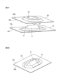
- Fig. 1A is a schematic diagram of a structure according to embodiment 1.
- Fig. 1B is a diagram of one metal plate seen from the front side.
- Fig. 1C is a diagram of the other metal plate seen from the back side.
- Fig. 2A is a schematic perspective view of a structure according to embodiment 1.
- Fig. 2B is a perspective view of one of the metal plates.
- 3A is a cross-sectional view showing a fastening operation in the structure according to the first embodiment
- FIG 3B is a cross-sectional view showing a state before one metal plate and another metal plate are fastened to each other
- FIG 3B is a cross-sectional view showing a state after one metal plate and another metal plate are fastened to each other.
- FIG. 4A is a schematic diagram of a structure according to embodiment 2.
- Fig. 4B is a front view of one metal plate as viewed from the front side.
- Fig. 4C is a view of the other metal plate as viewed from the back side.
- 5A and 5B are cross-sectional views showing a fastening operation in a structure according to a second embodiment of the present invention, respectively, before fastening one metal plate to another metal plate, and after fastening one metal plate to the other metal plate.
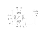
- Fig. 6A is a schematic diagram of a structure according to embodiment 3.
- Fig. 6A is a front view of the structure according to embodiment 3.
- Fig. 6B is a view of one metal plate as viewed from the front side.
- Fig. 6C is a view of the other metal plate as viewed from the back side.
- 13 is a view of the other metal plate in the structure according to embodiment 3, seen from the back side.
- FIG. FIG. 13 is a schematic diagram of a
- Embodiment 1 A structure according to a first embodiment will be described with reference to FIGS. 1 to 3.
- FIG. 1 A structure according to a first embodiment will be described with reference to FIGS. 1 to 3.
- FIG. 1 A structure according to a first embodiment will be described with reference to FIGS. 1 to 3.
- FIG. 1 A structure according to a first embodiment will be described with reference to FIGS. 1 to 3.
- FIG. 1 A structure according to a first embodiment will be described with reference to FIGS. 1 to 3.
- Fig. 1 is a schematic diagram of the structure according to the first embodiment.
- Fig. 2 is a schematic perspective view of the structure according to the first embodiment.
- Fig. 3 is a diagram showing the fastening operation of the structure according to the first embodiment.
- the structure according to the first embodiment is applied between two metal plates 10, 20 that are stacked on top of each other in the thickness direction, among multiple metal plates that make up the housing (not shown) of an electronic device.
- the metal sheets 10 and 20 are composed of a conductive base material and an insulating coating (the surface layer of the metal sheets 10 and 20) that is formed on the front and back surfaces of the base material.
- the base material is, for example, a conductor such as a metal.
- the insulating coating is, for example, a paint coating or a protective coating for preventing corrosion.
- One metal sheet 10 and the other metal sheet 20 are overlapped with portions facing each other, and the overlapped portions are fastened by screws 51. These screws 51 constitute the fastening member.
- the fastening member may also be a rivet, a snap fit, or the like.
- the metal plate 10 has a protruding portion 11 and an elastically deforming portion 12.
- the protruding portion 11 and the elastically deforming portion 12 are provided in the area of the metal plate 10 facing the metal plate 20.
- the metal sheet 10 has a front surface 10a, a back surface 10b, and a screw hole 10c.
- the front surface 10a is the surface facing the metal sheet 20.
- the back surface 10b is the surface located opposite the front surface 10a.
- the screw hole 10c penetrates the metal sheet 10 in the thickness direction. That is, the screw hole 10c opens on both the front surface 10a and the back surface 10b. A screw 51 can be tightened into the screw hole 10c.
- the protrusion 11 protrudes outward from the surface 10a of the metal sheet 10. In other words, the protrusion 11 protrudes from the surface 10a of the metal sheet 10 toward the metal sheet 20.
- This protrusion 11 is formed by deforming the entire thickness of the metal sheet 10. In other words, the protrusion 11 is formed by the surface 10a and the back surface 10b of the metal sheet 10 as one unit.
- the cross section of the protrusion 11 perpendicular to the longitudinal direction is substantially triangular.
- One apex of this triangle forms the tip of the protrusion 11. This tip extends linearly.
- the elastic deformation portion 12 is provided in a ring shape so as to surround the periphery of the protrusion 11.
- the protrusion 11 and the elastic deformation portion 12 are formed continuously. Specifically, the outer peripheral edge of the protrusion 11 and the inner peripheral edge of the elastic deformation portion 12 are smoothly connected without any seams.
- the elastic deformation portion 12 protrudes outward from the rear surface 10b of the metal sheet 10.
- the elastic deformation portion 12 protrudes from the rear surface 10b of the metal sheet 10 in a direction away from the metal sheet 20.
- the direction in which the protruding portion 11 protrudes from the metal sheet 10 and the direction in which the elastic deformation portion 12 protrudes from the metal sheet 10 are opposite to each other.
- the elastic deformation portion 12 is formed by deforming the entire thickness of the metal sheet 10.
- the cross section of the elastic deformation portion 12 perpendicular to the circumferential direction is approximately triangular.
- the metal plate 20 has a protruding portion 21 and an elastically deforming portion 22.
- the protruding portion 21 and the elastically deforming portion 22 are provided in the area of the metal plate 20 facing the metal plate 10.
- the metal sheet 20 has a front surface 20a, a back surface 20b, and a screw through hole 20c.
- the front surface 20a is the surface facing the front surface 10a of the metal sheet 10.
- the back surface 20b is the surface located opposite the front surface 20a.
- the screw through hole 20c is a so-called blind hole that penetrates the metal sheet 20 in the thickness direction. That is, the screw through hole 20c is open on both the front surface 20a and the back surface 20b.
- the screw through hole 20c corresponds to the screw hole 10c, and the screw 51 can be passed through the screw through hole 20c.
- the protrusion 21 protrudes outward from the surface 20a of the metal sheet 20. In other words, the protrusion 21 protrudes from the surface 20a of the metal sheet 20 toward the metal sheet 10.
- This protrusion 21 is formed by deforming the entire thickness of the metal sheet 20. In other words, the protrusion 21 is formed by integrating the surface 20a and the back surface 20b of the metal sheet 20.
- the cross section of the protrusion 21 perpendicular to the longitudinal direction is substantially triangular.
- One apex of this triangle forms the tip of the protrusion 21. This tip extends linearly.
- the elastic deformation portion 22 is provided in a ring shape so as to surround the periphery of the protrusion 21.
- the protrusion 21 and the elastic deformation portion 22 are formed continuously. Specifically, the outer peripheral edge of the protrusion 21 and the inner peripheral edge of the elastic deformation portion 22 are smoothly connected without any seams.
- the elastic deformation portion 22 protrudes outward from the rear surface 20b of the metal sheet 20.
- the elastic deformation portion 22 protrudes from the rear surface 20b of the metal sheet 20 in a direction away from the metal sheet 10.
- the direction in which the protruding portion 21 protrudes from the metal sheet 20 and the direction in which the elastic deformation portion 22 protrudes from the metal sheet 20 are opposite to each other.
- the elastic deformation portion 22 is formed by deforming the entire thickness of the metal sheet 20.
- the cross section of the elastic deformation portion 22 perpendicular to the circumferential direction is approximately triangular.
- the metal sheets 10 and 20 are arranged so that the tip of the protruding portion 11 and the tip of the protruding portion 21 intersect with each other.
- the surface 10a of the metal plate 10 and the surface 20a of the metal plate 20 are arranged to face each other.
- the metal plates 10 and 20 are arranged so that the tip of the protruding portion 11 and the tip of the protruding portion 21 intersect.
- the screw 51 is tightened into the screw hole 10c of the metal sheet 10 through the screw through hole 20c of the metal sheet 20.
- the metal sheets 10 and 20 are fastened together by the screw 51.
- the tip of the protrusion 11 and the tip of the protrusion 21 come into contact with each other, and pressure is concentrated in a small area.
- the insulating coating at the two tips is destroyed, and the base materials at the two tips come into contact with each other.
- the base material at the protrusion 11 and the base material at the protrusion 21 are conductive. Therefore, a path for noise current or leakage current is secured between the metal sheets 10 and 20.
- the elastic deformation portion 12 is elastically deformed as the protrusion 11 is pressed against the back surface 10b.
- the elastic deformation portion 22 is elastically deformed as the protrusion 21 is pressed against the back surface 20b.
- the structure of embodiment 1 has elastically deforming portions 12, 22, and so can maintain contact between the protrusions 11, 21 by utilizing the elastic deformation of the elastically deforming portions 12, 22, in other words, the return force of the elastically deforming portions 12, 22 to their original shape (position). For this reason, even if the screw 51 becomes loose, electrical continuity between the metal sheets 10, 20 can be maintained, and the effects of noise currents or leakage currents can be prevented.
- the structure according to the first embodiment is a structure in which a plurality of metal sheets 10, 20, each having a conductive base material covered with an insulating film, are stacked in the thickness direction, and includes one protruding portion 11 provided on one of the metal sheets 10 and protruding toward the other metal sheet 20, one elastically deforming portion 12 provided on the one metal sheet 10 so as to surround the periphery of the one protruding portion 11 and elastically deformed when fastened with the screw 51, the other protruding portion 21 on the other metal sheet 20 protruding toward the one metal sheet 10 and arranged to intersect with the one protruding portion 11, and the other elastically deforming portion 22 provided on the other metal sheet 20 so as to surround the periphery of the other protruding portion 21 and elastically deformed when fastened with the screw 51.
- the structure according to the first embodiment can ensure electrical continuity between the base materials of the metal sheets 10 and 20. Furthermore, the structure according to the first embodiment does not require special screws, washers, etc. to ensure electrical continuity between the base materials of the metal sheets 10 and 20.
- Embodiment 2 The structure according to the second embodiment will be described with reference to Fig. 4 and Fig. 5. Note that components having the same functions as those described in the first embodiment are given the same reference numerals, and the description thereof will be omitted.
- FIG. 4 is a schematic diagram of the structure according to the second embodiment.
- the structure according to the second embodiment has an elastic deformation portion 13 instead of the elastic deformation portion 12 of the metal plate 10.
- the elastic deformation portion 13 is provided in a ring shape so as to surround the periphery of the protrusion 11.
- the protrusion 11 and the elastic deformation portion 12 are formed continuously. Specifically, the outer peripheral edge of the protrusion 11 and the inner peripheral edge of the elastic deformation portion 12 are smoothly connected without any seams.
- the elastic deformation portion 13 protrudes outward from the rear surface 10b of the metal sheet 10. In other words, the elastic deformation portion 13 protrudes from the rear surface 10b of the metal sheet 10 in a direction away from the metal sheet 20.
- the elastic deformation portion 13 is formed by deforming the entire thickness of the metal sheet 10.
- the elastic deformation portion 12 is formed as described above, and is therefore capable of elastic deformation in the thickness direction of the metal sheet 10.
- the cross-sectional shape of the elastically deforming portion 13 perpendicular to the longitudinal direction of the tip of the protruding portion 11 is asymmetric on both sides of the tip.
- one side of the elastically deforming portion 13 centered on the tip of the protruding portion 11 has one bulging portion toward the back surface 10b.
- the other side of the elastically deforming portion 13 centered on the tip of the protruding portion 11 has one bulging portion toward the back surface 10b and one bulging portion toward the front surface 10a.
- the bulging portion toward the front surface 10a is positioned outside the sheet metal 10 relative to the bulging portion toward the back surface 10b.
- the elastic deformation portion 13 has a cross-sectional shape perpendicular to the longitudinal direction of the tip of the protrusion 11 that is asymmetric on both sides of the tip, so that a difference in the amount of elastic deformation can be achieved between the amount of elastic deformation on one side and the amount of elastic deformation on the other side of the tip of the protrusion 11.
- the other side of the elastic deformation portion 13 centered on the tip of the protrusion 11 has a more complex shape than the one side of the elastic deformation portion 13 centered on the tip of the protrusion 11.
- the amount of elastic deformation on the other side is greater than the amount of elastic deformation on that one side.
- FIG. 5 is a diagram showing the fastening operation of the structure according to the second embodiment. Note that the metal plate 20 is omitted in FIG. 5B.
- the surface 10a of the metal plate 10 and the surface 20a of the metal plate 20 are arranged to face each other.
- the metal plates 10 and 20 are arranged so that the tip of the protruding portion 11 and the tip of the protruding portion 21 intersect.
- the screw 51 is fastened to the screw hole 10c of the metal plate 10 through the screw through hole 20c of the metal plate 20.
- the metal plates 10 and 20 are fastened together by the screw 51.
- the tip of the protrusion 11 and the tip of the protrusion 21 come into contact with each other, and pressure is concentrated in a small area.
- the amount of elastic deformation on the other side of the elastic deformation portion 13 is greater than the amount of elastic deformation on the one side. Therefore, the tip position of the protrusion 11 shifts toward the other side. That is, the tip of the protrusion 11 moves along the length direction of the tip while contacting the tip of the protrusion 21.
- the insulating coating at the two tips is sufficiently destroyed, and the base materials at the two tips come into contact with each other.
- the base materials at the protrusion 11 and the base materials at the protrusion 21 are electrically connected to each other. Therefore, a path for noise current or leakage current is secured between the metal plates 10 and 20.
- the elastic deformation portion 13 is elastically deformed as the protrusion 11 is pressed against the back surface 10b.
- the elastic deformation portion 22 is elastically deformed as the protrusion 21 is pressed against the back surface 20b.
- the structure of embodiment 2 has elastically deforming portions 13, 22, and so can maintain contact between the protrusions 11, 21 by utilizing the elastic deformation of the elastically deforming portions 13, 22, in other words, the return force of the elastically deforming portions 13, 22 to their original shape (position). For this reason, even if the screw 51 becomes loose, electrical continuity between the metal sheets 10, 20 can be maintained, and the effects of noise currents or leakage currents can be prevented.
- the cross-sectional shape of the elastic deformation portion 13 in the metal plate 10 is asymmetric, but the cross-sectional shape of the elastic deformation portion 22 in the metal plate 20 may also be asymmetric.
- the cross-sectional shape of the elastically deforming portion 13 perpendicular to the longitudinal direction of the tip of the protruding portion 11 is asymmetric on both sides of the tip. Therefore, the structure according to the second embodiment can effectively peel off the insulating coating between the elastically deforming portion 13 and the tip and the tip of the elastically deforming portion 22.
- the tip of the protrusion 11 moves from the tip toward the side where the deformation of the elastic deformation portion 13 is greater. Therefore, the structure according to the second embodiment can expand the peeling range of the insulating coating, thereby improving electrical conductivity.
- the tip of protrusion 11 moves along the length direction of the tip of protrusion 21. Therefore, the structure according to embodiment 2 can maintain contact between the tip of protrusion 11 and the tip of protrusion 21 for a long period of time and distance. As a result, the structure according to embodiment 2 can expand the peeling range of the insulating coating.
- Embodiment 3 A structure according to the third embodiment will be described with reference to Fig. 6 and Fig. 7. Note that components having the same functions as those described in the first embodiment are given the same reference numerals, and the description thereof will be omitted.
- FIG. 6 is a schematic diagram of the structure according to the third embodiment.
- the structure according to embodiment 3 includes multiple pairs of protrusions 11 and elastic deformation portions 12, and one pair of protrusions 23 and elastic deformation portions 24.
- Figure 6 shows an example in which the structure according to embodiment 3 includes four pairs of protrusions 11 and elastic deformation portions 12, and one pair of protrusions 23 and elastic deformation portions 24.
- each pair of protrusions 11 and elastic deformation portions 12 are arranged at equal angular intervals around the screw hole 10c and the screw 51.
- the protrusions 23 and elastic deformation portions 24 are formed in a circular shape around the screw-through hole 20c and the screw 51.
- Four pairs of protrusions 11 and elastic deformation portions 12 and one set of protrusions 23 and elastic deformation portions 24 face each other in the plate thickness direction.
- the protrusion 23 protrudes outward from the surface 10a of the metal sheet 20.
- the protrusion 23 protrudes from the surface 20a of the metal sheet 20 toward the metal sheet 10.
- This protrusion 11 is formed by deforming the entire thickness of the metal sheet 10.
- the protrusion 11 is formed by integrating the surface 10a and the back surface 10b of the metal sheet 10.
- the cross section of the protrusion 23 perpendicular to the longitudinal direction is substantially triangular.
- One apex of this triangle forms the tip of the protrusion 23.
- This tip is formed in a circular shape with the screw-through hole 20c and the screw 51 at its center.
- the elastic deformation portion 24 is provided so as to surround the protruding portion 23. This elastic deformation portion 24 is disposed on the radial inner side and the radial outer side of the protruding portion 23. In other words, the elastic deformation portion 24 is disposed so as to sandwich the protruding portion 23 from both radial sides.
- the elastic deformation portion 24 protrudes outward from the rear surface 20b of the metal sheet 20.
- the elastic deformation portion 24 protrudes from the rear surface 10b of the metal sheet 20 in a direction away from the metal sheet 20.
- the direction in which the protruding portion 23 protrudes from the metal sheet 20 and the direction in which the elastic deformation portion 24 protrudes from the metal sheet 10 are opposite to each other.
- the elastic deformation portion 24 is formed by deforming the entire thickness of the metal sheet 20.
- the cross section of the elastic deformation portion 24 perpendicular to the circumferential direction is approximately triangular.
- the structure according to the third embodiment has four sets of protrusions 11 and elastic deformation portions 12 for one set of protrusions 23 and elastic deformation portions 24, and therefore the probability that the insulating coating will be destroyed and a conductive path will be increased by 16 times compared to when one set of protrusions 11 and elastic deformation portions 12 is provided for one set of protrusions 21 and elastic deformation portions 22. Furthermore, the structure according to the third embodiment can reduce the resistance value between the metal sheets 10 and 20 during electrical conduction to one-fourth of that value. Furthermore, the structure according to the third embodiment can stabilize the metal sheets 10 and 20 when fastened. As a result, the structure can improve the assembly accuracy between the metal sheets 10 and 20.
- the structure according to the third embodiment may also adopt the configuration shown in FIG. 7.
- FIG. 7 is a view of another metal plate 20 in the structure according to the third embodiment, viewed from the back.
- the structure according to the third embodiment may have the same number of pairs of protruding portions 11 and elastically deforming portions 12 as the number of pairs of protruding portions 21 and elastically deforming portions 22, and each pair in the metal plate 10 may face each pair in the metal plate 20. Even when such a configuration is adopted, the same effect as above can be obtained.
- the protruding portion 23 and the elastically deforming portion 24 of the metal sheet 20 are formed in a circular shape, but the protruding portion 11 and the elastically deforming portion 12 of the metal sheet 10 may also be formed in a circular shape.
- the structure according to the third embodiment includes multiple pairs of protrusions 11 and elastic deformation portions 12, and one pair of protrusions 23 and elastic deformation portions 24, with each pair of protrusions 11 and elastic deformation portions 12 facing the pair of protrusions 23 and elastic deformation portions 24. Therefore, the structure according to the third embodiment can effectively peel off the insulating coating between the tip of the elastic deformation portion 12 and the tip of the elastic deformation portion 24.
- the protrusion 23 and the elastic deformation portion 24 are formed in a circular shape with the screw 51 at the center. Therefore, the structure according to embodiment 3 can stabilize the metal sheets 10, 20 when fastened. As a result, the structure according to embodiment 3 can improve the assembly accuracy between the metal sheets 10, 20.
- the number of pairs of protrusions 11 and elastic deformation parts 12 and the number of pairs of protrusions 21 and elastic deformation parts 22 are the same, and each pair of protrusions 11 and elastic deformation parts 12 and each pair of protrusions 21 and elastic deformation parts 22 face each other. Therefore, the structure according to embodiment 3 can effectively peel off the insulating coating between the tip of the elastic deformation part 12 and the tip of the elastic deformation part 22.
- each pair of protrusions 11 and elastic deformation portions 12 are arranged at equal angular intervals around the fastening member. Therefore, the structure according to embodiment 3 can stabilize the metal sheets 10 and 20 when fastening. As a result, the structure according to embodiment 3 can improve the assembly accuracy between the metal sheets 10 and 20.
- FIG. 8 is a schematic diagram of the structure according to the fourth embodiment. Note that the same reference numerals are used for components having the same functions as those described in the first embodiment, and the description thereof will be omitted.
- the structure according to the fourth embodiment includes metal sheets 10 and 20 as well as metal sheet 30.
- metal sheets 10, 20, and 30 are stacked in order in the thickness direction.
- Surface 10a of metal sheet 10 and surface 20a of metal sheet 20 face each other, and back surface 20b of metal sheet 20 and surface 30a of metal sheet 30 face each other. Therefore, back surface 20b and surface 30a form opposing surfaces.
- the metal plate 20 has a protrusion 25 and an elastic deformation portion 26.
- the protrusion 25 and the elastic deformation portion 26 are provided in the area of the metal plate 20 facing the metal plate 30.
- the protrusion 25 protrudes outward from the back surface 20b of the metal sheet 20. In other words, the protrusion 25 protrudes from the back surface 20b of the metal sheet 20 toward the metal sheet 30.
- This protrusion 25 is formed by deforming the entire thickness of the metal sheet 20. In other words, the protrusion 25 is formed by integrating the front surface 20a and the back surface 20b of the metal sheet 20.
- the cross section of the protrusion 25 perpendicular to the longitudinal direction is substantially triangular.
- One apex of this triangle forms the tip of the protrusion 25. This tip extends linearly.
- the elastic deformation portion 26 is provided in a ring shape so as to surround the periphery of the protrusion 25.
- the protrusion 25 and the elastic deformation portion 26 are formed continuously. Specifically, the outer peripheral edge of the protrusion 25 and the inner peripheral edge of the elastic deformation portion 26 are smoothly connected without any seams.
- the elastic deformation portion 26 protrudes outward from the surface 20a of the metal sheet 20.
- the elastic deformation portion 26 protrudes from the surface 20a of the metal sheet 20 in a direction away from the metal sheet 30.
- the direction in which the protrusion 25 protrudes from the metal sheet 20 and the direction in which the elastic deformation portion 26 protrudes from the metal sheet 20 are opposite to each other.
- the elastic deformation portion 26 is formed by deforming the entire thickness of the metal sheet 20.
- the cross section of the elastic deformation portion 26 perpendicular to the circumferential direction is approximately triangular.
- the metal plate 30 has a protruding portion 31 and an elastically deforming portion 32.
- the protruding portion 31 and the elastically deforming portion 32 are provided in the area of the metal plate 30 that faces the metal plate 20.
- the metal sheet 30 has a front surface 30a, a back surface 30b, and a screw through hole 30c.
- the front surface 30a is the surface facing the metal sheet 20.
- the back surface 30b is the surface located opposite the front surface 30a.
- the screw through hole 30c is a so-called blind hole that penetrates the metal sheet 30 in the thickness direction. That is, the screw through hole 30c is open on the front surface 30a and the back surface 30b.
- the screw through hole 30c corresponds to the screw hole 10c and the screw through hole 20c, and the screw 51 can be passed through the screw through hole 30c.
- the protrusion 31 protrudes outward from the surface 10a of the metal sheet 30. In other words, the protrusion 31 protrudes from the surface 10a of the metal sheet 30 toward the metal sheet 20.
- This protrusion 31 is formed by deforming the entire thickness of the metal sheet 30. In other words, the protrusion 31 is formed by integrating the surface 30a and the back surface 30b of the metal sheet 30.
- the cross section of the protrusion 31 perpendicular to the longitudinal direction is substantially triangular.
- One apex of this triangle forms the tip of the protrusion 31. This tip extends linearly.
- the elastic deformation portion 32 is provided in a ring shape so as to surround the periphery of the protrusion 31.
- the protrusion 31 and the elastic deformation portion 32 are formed continuously. Specifically, the outer peripheral edge of the protrusion 31 and the inner peripheral edge of the elastic deformation portion 32 are smoothly connected without any seams.
- the elastic deformation portion 32 protrudes outward from the rear surface 30b of the metal sheet 30.
- the elastic deformation portion 32 protrudes from the rear surface 30b of the metal sheet 30 in a direction away from the metal sheet 20.
- the direction in which the protruding portion 31 protrudes from the metal sheet 10 and the direction in which the elastic deformation portion 32 protrudes from the metal sheet 10 are opposite to each other.
- the elastic deformation portion 32 is formed by deforming the entire thickness of the metal sheet 30.
- the cross section of the elastic deformation portion 32 perpendicular to the circumferential direction is approximately triangular.
- one metal plate 20 and the other metal plate 30 are arranged so that the tip of the protrusion 25 and the tip of the protrusion 31 intersect with each other.
- the structure according to the fourth embodiment is a structure in which a plurality of metal sheets 10, 20, 30, each having a conductive base material covered with an insulating film, are stacked in the thickness direction, and includes one protruding portion 25 provided on one of the metal sheets 20 and protruding toward the other metal sheet 30, one elastic deformation portion 26 provided on the one metal sheet 20 so as to surround the periphery of the one protruding portion 25 and elastically deforms when fastened with the screw 51, the other protruding portion 31 on the other metal sheet 30 protruding toward the one metal sheet 20 and arranged to intersect with the one protruding portion 25, and the other elastic deformation portion 32 provided on the other metal sheet 30 so as to surround the periphery of the other protruding portion 31 and elastically deforms when fastened with the screw 51.
- the structure according to the fourth embodiment can ensure electrical continuity between the base materials of the metal sheets 20 and 30 even if the screw 51 becomes loose. Furthermore, the structure according to the fourth embodiment does not require special screws, washers, etc. to ensure electrical continuity between the base materials of the metal sheets 30 and 30.
- the structure disclosed herein is suitable for use in structures and the like, since it is possible to ensure electrical continuity between the base metal sheets by providing an elastically deformable portion that surrounds the periphery of the protrusion.
Landscapes
- Engineering & Computer Science (AREA)
- Microelectronics & Electronic Packaging (AREA)
- Physics & Mathematics (AREA)
- Electromagnetism (AREA)
- Connection Of Plates (AREA)
Priority Applications (5)
| Application Number | Priority Date | Filing Date | Title |
|---|---|---|---|
| PCT/JP2023/024540 WO2025009008A1 (ja) | 2023-07-03 | 2023-07-03 | 構造体 |
| JP2024572607A JP7654179B1 (ja) | 2023-07-03 | 2023-07-03 | 構造体 |
| EP23944262.7A EP4730930A1 (en) | 2023-07-03 | 2023-07-03 | Structure |
| CN202380099741.7A CN121420634A (zh) | 2023-07-03 | 2023-07-03 | 结构体 |
| US19/370,924 US20260052663A1 (en) | 2023-07-03 | 2025-10-28 | Structure |
Applications Claiming Priority (1)
| Application Number | Priority Date | Filing Date | Title |
|---|---|---|---|
| PCT/JP2023/024540 WO2025009008A1 (ja) | 2023-07-03 | 2023-07-03 | 構造体 |
Related Child Applications (1)
| Application Number | Title | Priority Date | Filing Date |
|---|---|---|---|
| US19/370,924 Continuation US20260052663A1 (en) | 2023-07-03 | 2025-10-28 | Structure |
Publications (1)
| Publication Number | Publication Date |
|---|---|
| WO2025009008A1 true WO2025009008A1 (ja) | 2025-01-09 |
Family
ID=94171647
Family Applications (1)
| Application Number | Title | Priority Date | Filing Date |
|---|---|---|---|
| PCT/JP2023/024540 Ceased WO2025009008A1 (ja) | 2023-07-03 | 2023-07-03 | 構造体 |
Country Status (5)
| Country | Link |
|---|---|
| US (1) | US20260052663A1 (https=) |
| EP (1) | EP4730930A1 (https=) |
| JP (1) | JP7654179B1 (https=) |
| CN (1) | CN121420634A (https=) |
| WO (1) | WO2025009008A1 (https=) |
Citations (5)
| Publication number | Priority date | Publication date | Assignee | Title |
|---|---|---|---|---|
| JPS4718727U (https=) | 1971-04-01 | 1972-11-01 | ||
| JPS6035584U (ja) * | 1983-08-17 | 1985-03-11 | 松下電器産業株式会社 | 電子機器用筐体 |
| JPS60138268U (ja) * | 1984-02-24 | 1985-09-12 | 富士通株式会社 | カバ−のア−ス接続構造 |
| JP2000133971A (ja) * | 1998-10-22 | 2000-05-12 | Nec Eng Ltd | 部品の取付構造 |
| JP2023044113A (ja) * | 2021-09-17 | 2023-03-30 | キヤノン株式会社 | 結合構造及び画像形成装置 |
Family Cites Families (1)
| Publication number | Priority date | Publication date | Assignee | Title |
|---|---|---|---|---|
| JP7686514B2 (ja) * | 2021-09-17 | 2025-06-02 | キヤノン株式会社 | 画像形成装置の製造方法 |
-
2023
- 2023-07-03 EP EP23944262.7A patent/EP4730930A1/en active Pending
- 2023-07-03 WO PCT/JP2023/024540 patent/WO2025009008A1/ja not_active Ceased
- 2023-07-03 JP JP2024572607A patent/JP7654179B1/ja active Active
- 2023-07-03 CN CN202380099741.7A patent/CN121420634A/zh active Pending
-
2025
- 2025-10-28 US US19/370,924 patent/US20260052663A1/en active Pending
Patent Citations (5)
| Publication number | Priority date | Publication date | Assignee | Title |
|---|---|---|---|---|
| JPS4718727U (https=) | 1971-04-01 | 1972-11-01 | ||
| JPS6035584U (ja) * | 1983-08-17 | 1985-03-11 | 松下電器産業株式会社 | 電子機器用筐体 |
| JPS60138268U (ja) * | 1984-02-24 | 1985-09-12 | 富士通株式会社 | カバ−のア−ス接続構造 |
| JP2000133971A (ja) * | 1998-10-22 | 2000-05-12 | Nec Eng Ltd | 部品の取付構造 |
| JP2023044113A (ja) * | 2021-09-17 | 2023-03-30 | キヤノン株式会社 | 結合構造及び画像形成装置 |
Also Published As
| Publication number | Publication date |
|---|---|
| US20260052663A1 (en) | 2026-02-19 |
| JPWO2025009008A1 (https=) | 2025-01-09 |
| JP7654179B1 (ja) | 2025-03-31 |
| EP4730930A1 (en) | 2026-04-22 |
| CN121420634A (zh) | 2026-01-27 |
Similar Documents
| Publication | Publication Date | Title |
|---|---|---|
| CN103597222B (zh) | 接地螺栓 | |
| EP1950775B1 (en) | Monolithic ceramic capacitor | |
| JPH10188728A (ja) | パネルスイッチ用可動接点体及びそれを用いたパネルスイッチ | |
| JP2013037791A (ja) | 回路基板と端子金具の接続構造 | |
| JP7654179B1 (ja) | 構造体 | |
| WO2022017426A1 (zh) | 一种电芯组件以及电池 | |
| JP2778754B2 (ja) | 電磁遮蔽ガスケツトテープ | |
| JP2019061950A (ja) | 感圧センサ | |
| US20250311125A1 (en) | Display assembly and electronic device | |
| JP7569626B2 (ja) | 圧着端子を備えるフレキシブルプリント配線板 | |
| US11677202B2 (en) | Contact ring for highly dynamic applications | |
| JP3302932B2 (ja) | Smaコネクタ | |
| JPH0644131Y2 (ja) | 基板用スペーサー | |
| US4486810A (en) | Electrode lead tab for capacitor | |
| CN221727468U (zh) | 一种压铆螺母和电气连接端子 | |
| JP4011530B2 (ja) | コネクタ | |
| KR19990029632A (ko) | 가변 커패시터 | |
| JP5194084B2 (ja) | アースストラップ | |
| JP3046785B2 (ja) | プッシュオン式スイッチ | |
| JP3063235B2 (ja) | 積層型圧電アクチュエータ | |
| JPH0523367U (ja) | プツシユスイツチ | |
| JP2001126968A (ja) | 薄形電気二重層コンデンサ | |
| JP2902913B2 (ja) | 接点パネル | |
| JP2018532247A (ja) | コネクタ用の遮蔽要素および突出する切断部を有するハウジングアセンブリ | |
| JP3999930B2 (ja) | 高周波電流接触子およびこの接触子を用いた高エネルギ機器 |
Legal Events
| Date | Code | Title | Description |
|---|---|---|---|
| WWE | Wipo information: entry into national phase |
Ref document number: 2024572607 Country of ref document: JP |
|
| 121 | Ep: the epo has been informed by wipo that ep was designated in this application |
Ref document number: 23944262 Country of ref document: EP Kind code of ref document: A1 |
|
| WWE | Wipo information: entry into national phase |
Ref document number: 2023944262 Country of ref document: EP |
|
| ENP | Entry into the national phase |
Ref document number: 2023944262 Country of ref document: EP Effective date: 20260115 |
|
| ENP | Entry into the national phase |
Ref document number: 2023944262 Country of ref document: EP Effective date: 20260115 |
|
| ENP | Entry into the national phase |
Ref document number: 2023944262 Country of ref document: EP Effective date: 20260115 |
|
| NENP | Non-entry into the national phase |
Ref country code: DE |
|
| ENP | Entry into the national phase |
Ref document number: 2023944262 Country of ref document: EP Effective date: 20260115 |
|
| WWP | Wipo information: published in national office |
Ref document number: 2023944262 Country of ref document: EP |