WO2025005295A1 - 送風構造および空気調和機の室内機 - Google Patents
送風構造および空気調和機の室内機 Download PDFInfo
- Publication number
- WO2025005295A1 WO2025005295A1 PCT/JP2024/023661 JP2024023661W WO2025005295A1 WO 2025005295 A1 WO2025005295 A1 WO 2025005295A1 JP 2024023661 W JP2024023661 W JP 2024023661W WO 2025005295 A1 WO2025005295 A1 WO 2025005295A1
- Authority
- WO
- WIPO (PCT)
- Prior art keywords
- blowing
- air
- porous material
- dimension
- tongue
- Prior art date
- Legal status (The legal status is an assumption and is not a legal conclusion. Google has not performed a legal analysis and makes no representation as to the accuracy of the status listed.)
- Ceased
Links
Images



Classifications
-
- F—MECHANICAL ENGINEERING; LIGHTING; HEATING; WEAPONS; BLASTING
- F04—POSITIVE - DISPLACEMENT MACHINES FOR LIQUIDS; PUMPS FOR LIQUIDS OR ELASTIC FLUIDS
- F04D—NON-POSITIVE-DISPLACEMENT PUMPS
- F04D17/00—Radial-flow pumps, e.g. centrifugal pumps; Helico-centrifugal pumps
- F04D17/02—Radial-flow pumps, e.g. centrifugal pumps; Helico-centrifugal pumps having non-centrifugal stages, e.g. centripetal
- F04D17/04—Radial-flow pumps, e.g. centrifugal pumps; Helico-centrifugal pumps having non-centrifugal stages, e.g. centripetal of transverse-flow type
-
- F—MECHANICAL ENGINEERING; LIGHTING; HEATING; WEAPONS; BLASTING
- F24—HEATING; RANGES; VENTILATING
- F24F—AIR-CONDITIONING; AIR-HUMIDIFICATION; VENTILATION; USE OF AIR CURRENTS FOR SCREENING
- F24F1/00—Room units for air-conditioning, e.g. separate or self-contained units or units receiving primary air from a central station
- F24F1/0007—Indoor units, e.g. fan coil units
- F24F1/0011—Indoor units, e.g. fan coil units characterised by air outlets
-
- F—MECHANICAL ENGINEERING; LIGHTING; HEATING; WEAPONS; BLASTING
- F04—POSITIVE - DISPLACEMENT MACHINES FOR LIQUIDS; PUMPS FOR LIQUIDS OR ELASTIC FLUIDS
- F04D—NON-POSITIVE-DISPLACEMENT PUMPS
- F04D29/00—Details, component parts, or accessories
- F04D29/40—Casings; Connections of working fluid
- F04D29/42—Casings; Connections of working fluid for radial or helico-centrifugal pumps
- F04D29/4206—Casings; Connections of working fluid for radial or helico-centrifugal pumps especially adapted for elastic fluid pumps
- F04D29/4226—Fan casings
-
- F—MECHANICAL ENGINEERING; LIGHTING; HEATING; WEAPONS; BLASTING
- F24—HEATING; RANGES; VENTILATING
- F24F—AIR-CONDITIONING; AIR-HUMIDIFICATION; VENTILATION; USE OF AIR CURRENTS FOR SCREENING
- F24F1/00—Room units for air-conditioning, e.g. separate or self-contained units or units receiving primary air from a central station
- F24F1/0007—Indoor units, e.g. fan coil units
-
- F—MECHANICAL ENGINEERING; LIGHTING; HEATING; WEAPONS; BLASTING
- F24—HEATING; RANGES; VENTILATING
- F24F—AIR-CONDITIONING; AIR-HUMIDIFICATION; VENTILATION; USE OF AIR CURRENTS FOR SCREENING
- F24F1/00—Room units for air-conditioning, e.g. separate or self-contained units or units receiving primary air from a central station
- F24F1/0007—Indoor units, e.g. fan coil units
- F24F1/0018—Indoor units, e.g. fan coil units characterised by fans
- F24F1/0025—Cross-flow or tangential fans
-
- F—MECHANICAL ENGINEERING; LIGHTING; HEATING; WEAPONS; BLASTING
- F24—HEATING; RANGES; VENTILATING
- F24F—AIR-CONDITIONING; AIR-HUMIDIFICATION; VENTILATION; USE OF AIR CURRENTS FOR SCREENING
- F24F1/00—Room units for air-conditioning, e.g. separate or self-contained units or units receiving primary air from a central station
- F24F1/0007—Indoor units, e.g. fan coil units
- F24F1/0043—Indoor units, e.g. fan coil units characterised by mounting arrangements
- F24F1/0057—Indoor units, e.g. fan coil units characterised by mounting arrangements mounted in or on a wall
-
- F—MECHANICAL ENGINEERING; LIGHTING; HEATING; WEAPONS; BLASTING
- F24—HEATING; RANGES; VENTILATING
- F24F—AIR-CONDITIONING; AIR-HUMIDIFICATION; VENTILATION; USE OF AIR CURRENTS FOR SCREENING
- F24F13/00—Details common to, or for air-conditioning, air-humidification, ventilation or use of air currents for screening
- F24F13/20—Casings or covers
-
- F—MECHANICAL ENGINEERING; LIGHTING; HEATING; WEAPONS; BLASTING
- F24—HEATING; RANGES; VENTILATING
- F24F—AIR-CONDITIONING; AIR-HUMIDIFICATION; VENTILATION; USE OF AIR CURRENTS FOR SCREENING
- F24F13/00—Details common to, or for air-conditioning, air-humidification, ventilation or use of air currents for screening
- F24F13/22—Means for preventing condensation or evacuating condensate
- F24F13/222—Means for preventing condensation or evacuating condensate for evacuating condensate
-
- F—MECHANICAL ENGINEERING; LIGHTING; HEATING; WEAPONS; BLASTING
- F24—HEATING; RANGES; VENTILATING
- F24F—AIR-CONDITIONING; AIR-HUMIDIFICATION; VENTILATION; USE OF AIR CURRENTS FOR SCREENING
- F24F13/00—Details common to, or for air-conditioning, air-humidification, ventilation or use of air currents for screening
- F24F13/24—Means for preventing or suppressing noise
Definitions
- This disclosure relates to a ventilation structure and an indoor unit of an air conditioner.
- Patent Document 1 The technology described in Patent Document 1 is known as a technology related to crossflow fans.
- the entire fan casing is made of a porous material.
- An object of the present disclosure is to provide a ventilation structure and an indoor unit of an air conditioner that can suitably suppress noise.
- the second aspect of the air blowing structure is the first aspect of the air blowing structure, except that a heat exchanger is disposed above the first member, and a drain pan surface that receives condensation water from the heat exchanger is formed on the upper surface of the blowing portion, and the porous material is provided from a portion of the drain pan surface that does not face the heat exchanger to the lower surface of the blowing portion.
- This configuration allows an air layer to be created between the drain pan surface and the underside of the first member, so the ventilation structure can further reduce noise.
- the porous material suppresses pressure fluctuations near the tongue, where turbulence is likely to occur, reducing noise.
- the porous material suppresses pressure fluctuations near the tongue, where turbulence is likely to occur, reducing noise. Therefore, the air blowing structure can effectively suppress noise.
- This configuration allows the provision of porous material near the tongue, where turbulence is likely to occur, effectively suppressing noise.
- the sixteenth aspect of the airflow structure is the fifth aspect of the airflow structure, in which the second width has a dimension that is 50% or more of the first width.
- the first side portion 37 is connected to one end of the top surface portion 32, the first front surface portion 33, the second front surface portion 34, the rear surface portion 35, and the bottom surface portion 36 in the longitudinal direction X.
- the second side portion 38 is connected to the other end of the top surface portion 32, the first front surface portion 33, the second front surface portion 34, the rear surface portion 35, and the bottom surface portion 36 in the longitudinal direction X.
- the heat exchanger 12 exchanges heat with the air drawn in through the suction port 39.
- the heat exchanger 12 has multiple fins and multiple heat transfer tubes that pass through the multiple fins.
- the heat exchanger 12 exchanges heat between the refrigerant flowing through the heat transfer tubes and the air passing through the heat exchanger 12.
- the heat exchanger 12 functions as an evaporator or a condenser depending on the operating state of the indoor unit 11.
- the heat exchanger 12 is placed in the internal space IS of the case portion 31 so that at least a portion of the heat exchanger 12 is located closer to the suction port 39 than the crossflow fan 22.
- the air filter 13 collects dust in the indoor air sucked in from the suction port 39.
- the air filter 13 prevents dust in the indoor air from adhering to the surface of the heat exchanger 12.
- the crossflow fan 22 is a generally cylindrical impeller extending in the longitudinal direction X.
- the crossflow fan 22 is provided in the internal space IS of the case portion 31.
- the crossflow fan 22 has blade edges 23 provided on the outer periphery of the crossflow fan 22.
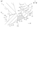
- the portion of the blowing section 43 made of the porous material 51 has a first end 52 on the blowing outlet 40 side.
- the first end 52 is the end on the downstream side of the air flow caused by the crossflow fan 22.
- the first end 52 is closer to the tongue portion 44 than to the blowing outlet 40.
- the portion of the blowing section 43 made of the porous material 51 has a second end 53 on the tongue 44 side.
- the second end 53 is the upstream end of the air flow caused by the crossflow fan 22.
- the second end 53 comes into contact with the tongue 44.
- the portion of the blowing section 43 made of porous material 51 faces both the blowing region BR and the suction region SR.
- the portion of the blowing section 43 made of porous material 51 has a first end face 54 that faces the blowing region BR.
- the portion of the blowing section 43 made of porous material 51 has a second end face 55 that faces the suction region SR.
- FIG. 4 shows an example of a graph comparing the loudness of the blowing noise versus air volume for pattern 1 and pattern 2.
- Pattern 1 is a case where porous material 51 is provided in blowing portion 43, and further porous material 51 is provided in tongue portion 44.
- Pattern 2 is a case where porous material 51 is provided in blowing portion 43, and porous material 51 is not provided in tongue portion 44.
- the solid line in FIG. 4 is a graph of the loudness of the blowing noise versus air volume for pattern 1.
- the dashed line in FIG. 4 is a graph of the loudness of the blowing noise versus air volume for pattern 2.
- the volume of the blowing noise relative to the air volume in pattern 1 is greater than the volume of the blowing noise relative to the air volume in pattern 2. In other words, the blowing noise can be reduced more in pattern 2 than in pattern 1.
- the first wall surface 45 has a third dimension S3 from the air outlet 40 to the end of the porous material 51 on the air outlet 40 side.
- the first dimension S1 is the distance between the end of the first wall surface 45 on the downstream side of the air flow caused by the crossflow fan 22 and the end of the porous material 51 on the downstream side of the air flow caused by the crossflow fan 22 on the first wall surface 45.
- the third dimension S3 is longer than the second dimension S2.
- the third dimension S3 is 70% or more of the first dimension S1.
- the third dimension S3 is 80% or more of the first dimension S1.
- the first width L1 is 10% or more of the first dimension S1.
- the porous material 51 is provided on the crossflow fan 22 side of the first member 41 rather than near the air outlet 40 where the user's hands are likely to touch, so the first member 41 is less likely to be damaged and the appearance and shape of the indoor unit 11 can be maintained.
- the heat exchanger 12 is disposed above the first member 41, and a drain pan surface 41a that receives condensation water from the heat exchanger 12 is formed on the upper surface 43a of the blowing section 43, and the porous material 51 is provided from the portion of the drain pan surface 41a that does not face the heat exchanger 12 to the lower surface 43b of the blowing section 43.
- the porous material 51 is provided in a portion of the blowing section 43 that is different from the portion that has the lowest vertical height. With this configuration, the portion of the drain pan surface 41a where moisture is likely to accumulate is not porous, so that the air blowing structure 21 is less likely to allow moisture that has accumulated on the drain pan surface 41a to leak downward.
- the porous material 51 is positioned downstream of the air flow caused by the crossflow fan 22 from the tongue portion 44 of the blowing section 43.
- the end downstream of the air flow caused by the crossflow fan 22 in the portion of the blowing section 43 made of the porous material 51 is closer to the tongue portion 44 than the blowing port 40 from which the sucked air is blown out.
- the blowing area BR is formed by a first wall surface 45 on the first member 41 side and a second wall surface 46 on the opposite side of the first wall surface 45 with respect to the blowing area BR, and the tongue portion 44 has an inner end 44a located on the blowing area BR side, and the first wall surface 45 has a first dimension S1 from the blowing outlet 40 to the inner end 44a, a second dimension S2 from the blowing outlet 40 to a position that is 60% of the first dimension S1, and a third dimension S3 from the blowing outlet 40 to the end of the part of the blowing section 43 made of the porous material 51 on the blowing outlet 40 side, and the third dimension S3 is longer than the second dimension S2.
- the porous material 51 can be provided near the tongue portion 44 where turbulence is likely to occur, so that the air blowing structure 21 can effectively suppress noise.
- the porous material 51 has a structure that allows air to pass through, and faces both the blowing area BR and the suction area SR. Near the tongue 44, the air flows through the gap between the crossflow fan 22 and the tongue 44, and the flow toward the suction area SR and the flow toward the blowing outlet 40 merge. For this reason, turbulence is likely to occur and grow due to the collision of the air flow with the tongue 44, the mixing of the flows, and friction on the wall surface.
Landscapes
- Engineering & Computer Science (AREA)
- Mechanical Engineering (AREA)
- General Engineering & Computer Science (AREA)
- Chemical & Material Sciences (AREA)
- Combustion & Propulsion (AREA)
- Air-Conditioning Room Units, And Self-Contained Units In General (AREA)
- Structures Of Non-Positive Displacement Pumps (AREA)
- Air Filters, Heat-Exchange Apparatuses, And Housings Of Air-Conditioning Units (AREA)
Abstract
Description
本開示の目的の1つは、好適に騒音を抑制できる送風構造および空気調和機の室内機を提供することである。
この構成によれば、第2幅が第1幅よりも短いため、多孔質材と舌部との接触面積を増やすことができる。
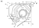
図1から図5を参照して、本実施形態の送風構造21および空気調和機の室内機11を説明する。
図1から図3に示される空気調和機の室内機11は、居室内の空間の冷房または暖房を行うように構成される。室内機11は、室内の壁WLに取り付けられる壁掛け型である。室内機11は、空気調和機の室外機に冷媒配管によって接続される。
多孔質材51は、空気を透過するような構造を有する。多孔質材51の材質は特に制限されない。多孔質材51の材質は、例えば、樹脂、セラミックス、金属等である。例えば、樹脂は、発泡樹脂である。例えば、セラミックスまたは金属は、多孔質焼結体である。金属は、メッシュともいう網状体であってもよい。
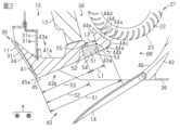
第1壁面45は、吹出口40から内端44aまでの第1寸法S1を有する。具体的には、第1寸法S1は、第1壁面45のクロスフローファン22による空気の流れの下流側の端部と、内端44aとの間の距離である。第1壁面45は、吹出口40から第1寸法S1の60%の位置までの第2寸法S2を有する。具体的には、第1寸法S1は、第1壁面45のクロスフローファン22による空気の流れの下流側の端部と、第1寸法S1の60%の位置との間の距離である。第1壁面45は、吹出口40から多孔質材51の吹出口40側の端部までの第3寸法S3を有する。具体的には、第1寸法S1は、第1壁面45のクロスフローファン22による空気の流れの下流側の端部と、第1壁面45における、多孔質材51のクロスフローファン22による空気の流れの下流側の端部との間の距離である。
(式1):S3/S1=0.85
(式2):L1/S1=0.13
(式3):L2/L1=0.83
(1)送風構造21は、クロスフローファン22と、クロスフローファン22が設けられるハウジング30と、を備える。ハウジング30は、空気が吸い込まれる吸込口39を有するケース部31と、第1部材41と、を有する。第1部材41は、クロスフローファン22に空気が吸い込まれる吸込領域SRとクロスフローファン22から空気が吹き出される吹出領域BRとを区画する舌部44と、舌部44より吹出口40側に位置する吹出部43と、を有する。舌部44は非多孔質材からなる。吹出部43の一部は多孔質材51からなる。多孔質材51は、吹出部43の上面43aから下面43bにわたって設けられている。
本開示の送風構造21および空気調和機の室内機11は、上記の実施形態以外に、例えば、以下に示される変更例および相互に矛盾しない少なくとも二つの変更例を組み合わせた形態としてもよい。
Claims (10)
- 送風構造(21)であって、
クロスフローファン(22)と、
前記クロスフローファン(22)が設けられるハウジング(30)と、を備え、
前記ハウジング(30)は、
空気が吸い込まれる吸込口(39)を有するケース部(31)と、
第1部材(41)と、を有し、
前記第1部材(41)は、
前記クロスフローファン(22)に空気が吸い込まれる吸込領域(SR)と前記クロスフローファン(22)から空気が吹き出される吹出領域(BR)とを区画する舌部(44)と、
前記舌部(44)より吹出口(40)側に位置する吹出部(43)と、を有し、
前記舌部(44)は非多孔質材からなり、
前記吹出部(43)の一部は多孔質材(51)からなり、
前記多孔質材(51)は、前記吹出部(43)の上面(43a)から下面(43b)にわたって設けられている、
送風構造。 - 前記第1部材(41)の上方には熱交換器(12)が配置されており、
前記吹出部(43)の上面(43a)には、前記熱交換器(12)からの結露水を受けるドレンパン面(41a)が形成されており、
前記多孔質材(51)は、前記ドレンパン面(41a)のうちの前記熱交換器(12)と対向しない部分から前記吹出部(43)の下面(43b)にわたって設けられている、
請求項1に記載の送風構造。 - 前記多孔質材(51)は、前記吹出部(43)のうちの鉛直方向における高さが最も低い部分とは異なる部分に設けられる、
請求項1または2に記載の送風構造。 - 前記多孔質材(51)は、前記吹出部(43)のうちの前記舌部(44)よりも前記クロスフローファン(22)による空気の流れの下流側に配置され、
前記吹出部(43)のうちの前記多孔質材(51)からなる部分における前記クロスフローファン(22)による空気の流れの下流側の端部は、吸い込まれた空気が吹き出される前記吹出口(40)よりも前記舌部(44)の近くにある、
請求項1から3のいずれか一項に記載の送風構造。 - 前記吹出領域(BR)は、前記第1部材(41)側の第1壁面(45)と、前記吹出領域(BR)に対して前記第1壁面(45)と反対側の第2壁面(46)とによって形成され、
前記舌部(44)は、前記吹出領域(BR)側に位置する内端(44a)を有し、
前記第1壁面(45)は、前記吹出口(40)から前記内端(44a)までの第1寸法(S1)と、前記吹出口(40)から前記第1寸法(S1)の60%の位置までの第2寸法(S2)と、前記吹出口(40)から前記吹出部(43)のうちの前記多孔質材(51)からなる部分の前記吹出口(40)側の端部までの第3寸法(S3)と、を有し、
前記第3寸法(S3)は、前記第2寸法(S2)よりも長い、
請求項4に記載の送風構造。 - 前記多孔質材(51)は、空気を透過するような構造を有し、かつ、前記吹出領域(BR)および前記吸込領域(SR)の両方に面する、
請求項5に記載の送風構造。 - 前記吹出部のうちの前記多孔質材(51)からなる部分は、前記吹出領域(BR)に面する第1端面(54)を有し、
前記第1端面(54)は、第1幅(L1)を有し、
前記第1幅(L1)は、前記第1寸法(S1)の10%以上の寸法を有する、
請求項6に記載の送風構造。 - 前記吹出部(43)のうちの前記多孔質材(51)からなる部分は、前記吸込領域(SR)に面する第2端面(55)を有し、
前記第2端面(55)は、第2幅(L2)を有し、
前記第2幅(L2)は、前記第1幅(L1)よりも短い、
請求項7に記載の送風構造。 - 前記第2幅(L2)は、前記第1幅(L1)の50%以上の寸法を有する、
請求項8に記載の送風構造。 - 空気調和機の室内機(11)であって、
請求項1から9のいずれか一項に記載の送風構造(21)と、
熱交換器(12)と、を備える、
室内機。
Priority Applications (3)
| Application Number | Priority Date | Filing Date | Title |
|---|---|---|---|
| CN202480041733.1A CN121358992A (zh) | 2023-06-30 | 2024-06-28 | 送风构造以及空调机的室内机 |
| EP24832151.5A EP4711681A1 (en) | 2023-06-30 | 2024-06-28 | Air blowing structure and indoor unit of air conditioner |
| US19/422,499 US20260104169A1 (en) | 2023-06-30 | 2025-12-17 | Air blowing structure and indoor unit of air conditioner |
Applications Claiming Priority (2)
| Application Number | Priority Date | Filing Date | Title |
|---|---|---|---|
| JP2023-108412 | 2023-06-30 | ||
| JP2023108412 | 2023-06-30 |
Related Child Applications (1)
| Application Number | Title | Priority Date | Filing Date |
|---|---|---|---|
| US19/422,499 Continuation US20260104169A1 (en) | 2023-06-30 | 2025-12-17 | Air blowing structure and indoor unit of air conditioner |
Publications (1)
| Publication Number | Publication Date |
|---|---|
| WO2025005295A1 true WO2025005295A1 (ja) | 2025-01-02 |
Family
ID=93938510
Family Applications (1)
| Application Number | Title | Priority Date | Filing Date |
|---|---|---|---|
| PCT/JP2024/023661 Ceased WO2025005295A1 (ja) | 2023-06-30 | 2024-06-28 | 送風構造および空気調和機の室内機 |
Country Status (5)
| Country | Link |
|---|---|
| US (1) | US20260104169A1 (ja) |
| EP (1) | EP4711681A1 (ja) |
| JP (1) | JP7653048B2 (ja) |
| CN (1) | CN121358992A (ja) |
| WO (1) | WO2025005295A1 (ja) |
Citations (4)
| Publication number | Priority date | Publication date | Assignee | Title |
|---|---|---|---|---|
| JPS61114000U (ja) | 1985-12-19 | 1986-07-18 | ||
| JPH08159509A (ja) * | 1994-12-07 | 1996-06-21 | Toshiba Corp | 空気調和機 |
| JPH08247526A (ja) * | 1995-03-10 | 1996-09-27 | Toshiba Corp | 空気調和機 |
| JPH11173595A (ja) * | 1997-12-15 | 1999-06-29 | Mitsubishi Electric Corp | 空気調和機の吸音装置 |
Family Cites Families (2)
| Publication number | Priority date | Publication date | Assignee | Title |
|---|---|---|---|---|
| JP2014062465A (ja) | 2012-09-19 | 2014-04-10 | Daikin Ind Ltd | クロスフローファン及びこれを備える空気調和装置 |
| JP6622548B2 (ja) | 2015-10-13 | 2019-12-18 | 三菱重工業株式会社 | 吸音構造及び空気調和装置 |
-
2024
- 2024-06-28 CN CN202480041733.1A patent/CN121358992A/zh active Pending
- 2024-06-28 EP EP24832151.5A patent/EP4711681A1/en active Pending
- 2024-06-28 JP JP2024105241A patent/JP7653048B2/ja active Active
- 2024-06-28 WO PCT/JP2024/023661 patent/WO2025005295A1/ja not_active Ceased
-
2025
- 2025-12-17 US US19/422,499 patent/US20260104169A1/en active Pending
Patent Citations (4)
| Publication number | Priority date | Publication date | Assignee | Title |
|---|---|---|---|---|
| JPS61114000U (ja) | 1985-12-19 | 1986-07-18 | ||
| JPH08159509A (ja) * | 1994-12-07 | 1996-06-21 | Toshiba Corp | 空気調和機 |
| JPH08247526A (ja) * | 1995-03-10 | 1996-09-27 | Toshiba Corp | 空気調和機 |
| JPH11173595A (ja) * | 1997-12-15 | 1999-06-29 | Mitsubishi Electric Corp | 空気調和機の吸音装置 |
Also Published As
| Publication number | Publication date |
|---|---|
| JP7653048B2 (ja) | 2025-03-28 |
| US20260104169A1 (en) | 2026-04-16 |
| JP2025010040A (ja) | 2025-01-20 |
| EP4711681A1 (en) | 2026-03-18 |
| CN121358992A (zh) | 2026-01-16 |
Similar Documents
| Publication | Publication Date | Title |
|---|---|---|
| JP6058242B2 (ja) | 空気調和機 | |
| CN1680753A (zh) | 空调器 | |
| CN103370578A (zh) | 空气调节机 | |
| JP2000291973A (ja) | 空気調和機の室内ユニット | |
| JP4678327B2 (ja) | 空気調和機 | |
| CN107076451A (zh) | 空调机 | |
| JP7653048B2 (ja) | 送風構造および空気調和機の室内機 | |
| JP4432702B2 (ja) | 送風ダクト | |
| JP3596422B2 (ja) | 空気調和機の室内ユニット | |
| JP3120959B2 (ja) | 送風機 | |
| JP2005037001A (ja) | 空気調和機の室内ユニット | |
| JP3055436B2 (ja) | 空気調和装置 | |
| JP7531172B2 (ja) | 空気調和機の室内機 | |
| JP2025007184A (ja) | フラップおよび空気調和機 | |
| JPH08159509A (ja) | 空気調和機 | |
| JP7678358B2 (ja) | 送風装置及び空調ユニット | |
| JP3331873B2 (ja) | 空気調和機の室内機 | |
| CN212901757U (zh) | 一种空调室内机及空调器 | |
| CN111322682B (zh) | 空调机 | |
| JP2019174008A (ja) | 熱交換器、および空気調和機の室内機 | |
| JP2010048470A (ja) | 空気調和機 | |
| JP2002081672A (ja) | 空気調和機 | |
| KR100598564B1 (ko) | 공기조화기의 실내기 | |
| JP2004271044A (ja) | 空気調和機の室内ユニット | |
| JPH07217931A (ja) | 空気調和機 |
Legal Events
| Date | Code | Title | Description |
|---|---|---|---|
| 121 | Ep: the epo has been informed by wipo that ep was designated in this application |
Ref document number: 24832151 Country of ref document: EP Kind code of ref document: A1 |
|
| WWE | Wipo information: entry into national phase |
Ref document number: 2024832151 Country of ref document: EP |
|
| ENP | Entry into the national phase |
Ref document number: 2024832151 Country of ref document: EP Effective date: 20251209 |
|
| WWE | Wipo information: entry into national phase |
Ref document number: 202517128781 Country of ref document: IN |
|
| ENP | Entry into the national phase |
Ref document number: 2024832151 Country of ref document: EP Effective date: 20251209 |
|
| ENP | Entry into the national phase |
Ref document number: 2024832151 Country of ref document: EP Effective date: 20251209 |
|
| ENP | Entry into the national phase |
Ref document number: 2024832151 Country of ref document: EP Effective date: 20251209 |
|
| WWP | Wipo information: published in national office |
Ref document number: 202517128781 Country of ref document: IN |
|
| ENP | Entry into the national phase |
Ref document number: 2024832151 Country of ref document: EP Effective date: 20251209 |
|
| ENP | Entry into the national phase |
Ref document number: 2024832151 Country of ref document: EP Effective date: 20251209 |
|
| ENP | Entry into the national phase |
Ref document number: 2024832151 Country of ref document: EP Effective date: 20251209 |
|
| NENP | Non-entry into the national phase |
Ref country code: DE |
|
| ENP | Entry into the national phase |
Ref document number: 2024832151 Country of ref document: EP Effective date: 20251209 |
|
| ENP | Entry into the national phase |
Ref document number: 2024832151 Country of ref document: EP Effective date: 20251209 |
|
| WWP | Wipo information: published in national office |
Ref document number: 2024832151 Country of ref document: EP |