WO2025005162A1 - 空気調和機、熱源モジュール、室内機および空気調和機の制御方法 - Google Patents
空気調和機、熱源モジュール、室内機および空気調和機の制御方法 Download PDFInfo
- Publication number
- WO2025005162A1 WO2025005162A1 PCT/JP2024/023266 JP2024023266W WO2025005162A1 WO 2025005162 A1 WO2025005162 A1 WO 2025005162A1 JP 2024023266 W JP2024023266 W JP 2024023266W WO 2025005162 A1 WO2025005162 A1 WO 2025005162A1
- Authority
- WO
- WIPO (PCT)
- Prior art keywords
- water
- indoor
- refrigerant
- heat exchanger
- unit
- Prior art date
- Legal status (The legal status is an assumption and is not a legal conclusion. Google has not performed a legal analysis and makes no representation as to the accuracy of the status listed.)
- Ceased
Links
Images

Classifications
-
- F—MECHANICAL ENGINEERING; LIGHTING; HEATING; WEAPONS; BLASTING
- F24—HEATING; RANGES; VENTILATING
- F24F—AIR-CONDITIONING; AIR-HUMIDIFICATION; VENTILATION; USE OF AIR CURRENTS FOR SCREENING
- F24F11/00—Control or safety arrangements
- F24F11/70—Control systems characterised by their outputs; Constructional details thereof
- F24F11/80—Control systems characterised by their outputs; Constructional details thereof for controlling the temperature of the supplied air
- F24F11/86—Control systems characterised by their outputs; Constructional details thereof for controlling the temperature of the supplied air by controlling compressors within refrigeration or heat pump circuits
-
- F—MECHANICAL ENGINEERING; LIGHTING; HEATING; WEAPONS; BLASTING
- F24—HEATING; RANGES; VENTILATING
- F24F—AIR-CONDITIONING; AIR-HUMIDIFICATION; VENTILATION; USE OF AIR CURRENTS FOR SCREENING
- F24F5/00—Air-conditioning systems or apparatus not covered by F24F1/00 or F24F3/00, e.g. using solar heat or combined with household units such as an oven or water heater
-
- F—MECHANICAL ENGINEERING; LIGHTING; HEATING; WEAPONS; BLASTING
- F24—HEATING; RANGES; VENTILATING
- F24F—AIR-CONDITIONING; AIR-HUMIDIFICATION; VENTILATION; USE OF AIR CURRENTS FOR SCREENING
- F24F2110/00—Control inputs relating to air properties
- F24F2110/10—Temperature
-
- F—MECHANICAL ENGINEERING; LIGHTING; HEATING; WEAPONS; BLASTING
- F24—HEATING; RANGES; VENTILATING
- F24F—AIR-CONDITIONING; AIR-HUMIDIFICATION; VENTILATION; USE OF AIR CURRENTS FOR SCREENING
- F24F2110/00—Control inputs relating to air properties
- F24F2110/50—Air quality properties
- F24F2110/64—Airborne particle content
-
- F—MECHANICAL ENGINEERING; LIGHTING; HEATING; WEAPONS; BLASTING
- F24—HEATING; RANGES; VENTILATING
- F24F—AIR-CONDITIONING; AIR-HUMIDIFICATION; VENTILATION; USE OF AIR CURRENTS FOR SCREENING
- F24F2140/00—Control inputs relating to system states
- F24F2140/20—Heat-exchange fluid temperature
Definitions
- the present invention relates to an air conditioner equipped with a relay unit that connects a refrigerant circuit and a water circuit, a heat source module, an indoor unit, and a method for controlling the air conditioner.
- An air conditioner includes a refrigerant circuit having a compressor that circulates refrigerant and an outdoor heat exchanger, a water circuit having a water-refrigerant heat exchanger and a pump that circulates water that exchanges heat with the refrigerant, and a number of indoor units connected to the water circuit or the water circuit and refrigerant circuit.
- a method is known for this type of air conditioner that controls the compressor speed during heating based on the temperature difference between the room temperature and the set temperature.
- Patent Document 1 the technology described in Patent Document 1 is premised on the connection of an indoor unit equipped with a means for detecting the indoor load, such as a sensor that detects the indoor temperature. For this reason, if an indoor unit that does not have a means for detecting the indoor load is connected, or if a natural convection heating unit such as a floor heating unit is connected, the above control cannot be performed.
- the object of the present invention is to provide an air conditioner, a heat source module, an indoor unit, and a control method for an air conditioner that can perform operation in accordance with the indoor load without relying on the function of the indoor unit.
- An air conditioner comprises: a primary refrigerant circuit including an outdoor unit having a compressor and an outdoor heat exchanger, and at least one relay unit having a water-refrigerant heat exchanger that exchanges heat between a refrigerant and water and connected to the outdoor unit, in which a primary refrigerant circulates;
- a secondary refrigerant circuit including at least one indoor unit having a water heat exchanger connected to the water-refrigerant heat exchanger and a circulation pump, in which a secondary refrigerant circulates;
- a control device for controlling the compressor The control device executes either a room temperature control mode in which the rotation speed of the compressor is controlled based on information about the indoor load, or a water temperature control mode in which the rotation speed of the compressor is controlled based on information about the thermal load of the secondary refrigerant circuit.
- the indoor unit may further have a room temperature sensor that detects the indoor temperature, and the control device may store a set temperature for the indoor temperature and calculate the indoor load based on the difference between the indoor temperature and the set temperature.
- the secondary refrigerant circuit may further include a water temperature sensor disposed downstream of the water-refrigerant heat exchanger to detect the temperature of the secondary refrigerant, and the control device may store a target temperature of the secondary refrigerant and calculate the heat load based on the difference between the temperature of the secondary refrigerant and the target temperature.
- the relay unit may further have a receiving unit that receives an input instruction from a user, and the control device may execute the water temperature control mode when the control device receives the input instruction via the receiving unit.
- the secondary refrigerant circuit may have a plurality of indoor units, and the control device may execute the room temperature control mode by receiving information about the indoor load transmitted from the indoor units, and when there is one or more indoor units for which the transmission of information about the indoor load cannot be confirmed, execute a water temperature control mode that controls the rotation speed of the compressor based on information about the heat load of the secondary refrigerant circuit.
- a heat source module includes: a primary refrigerant circuit including an outdoor unit having a compressor and an outdoor heat exchanger, and at least one relay unit having a water-refrigerant heat exchanger that exchanges heat between a refrigerant and water and connected to the outdoor unit, in which a primary refrigerant circulates;
- a control device for controlling the compressor The control device executes either a room temperature control mode in which the rotation speed of the compressor is controlled based on information about an indoor load transmitted from at least one indoor unit connected to the water-refrigerant heat exchanger and having a water heat exchanger, or a water temperature control mode in which the rotation speed of the compressor is controlled based on information about the thermal load of the secondary refrigerant circuit.
- An indoor unit is an indoor unit having a water heat exchanger connected to the heat source module and connected to the water-refrigerant heat exchanger,
- the control device includes an indoor load detection means for executing a room temperature control mode in which the rotation speed of the compressor is controlled based on information about the indoor load.
- a method for controlling an air conditioner includes: a primary refrigerant circuit including an outdoor unit having a compressor and an outdoor heat exchanger, and at least one relay unit having a water-refrigerant heat exchanger that exchanges heat between a refrigerant and water and connected to the outdoor unit, in which a primary refrigerant circulates;
- a secondary refrigerant circuit including at least one indoor unit having a water heat exchanger connected to the water-refrigerant heat exchanger and a circulation pump, in which a secondary refrigerant circulates;
- a control method for an air conditioner comprising: When the outdoor unit receives information regarding the indoor load transmitted from the indoor unit, a room temperature control mode is executed in which the rotation speed of the compressor is controlled based on the information regarding the indoor load. When the transmission of information regarding the indoor load from the indoor unit cannot be confirmed, a water temperature control mode is executed in which the rotation speed of the compressor is controlled based on information regarding the thermal load of the secondary refrigerant circuit.
- operation can be performed in accordance with the indoor load, regardless of the function of the indoor unit.
- FIG. 1 is a refrigerant-water circuit diagram of an air conditioner according to an embodiment of the present invention.
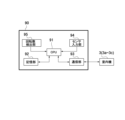
- 4 is a block diagram showing a configuration of a control device in the air conditioner.
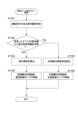
- FIG. 4 is a flowchart showing an example of a procedure for determining a control mode of a compressor executed in the control device.
- First Embodiment [Configuration of Air Conditioner] 1 is a refrigerant-water circuit diagram of an air conditioner 100 according to one embodiment of the present invention.
- the air conditioner 100 of this embodiment comprises an outdoor unit 2, a plurality of (three in this embodiment) indoor units 3a, 3b, 3c (hereinafter collectively referred to as indoor units 3 unless individually described), a relay unit 50, and a control device 90.
- the outdoor unit 2 and the relay unit 50 constitute a heat source module 55 in the air conditioner 100.
- the outdoor unit 2 has a compressor 21, a four-way valve 22, an outdoor heat exchanger 23, an expansion valve 24, and an accumulator 25.
- Each of these devices and the relay unit 50 are connected to each other through piping to form a refrigerant circuit 20 (primary refrigerant circuit) in the refrigerant-water circuit of the air conditioner 100.
- the relay unit 50 will be described later.
- Compressor 21 is a variable capacity compressor whose operating capacity can be varied by controlling the rotation speed with an inverter (not shown).
- the refrigerant discharge side of compressor 21 is connected to port a of four-way valve 22 via discharge pipe 61.
- the refrigerant suction side of compressor 21 is connected to the refrigerant outflow side of accumulator 25 via suction pipe 65.
- the four-way valve 22 is a valve for switching the direction of refrigerant flow, and has four ports a, b, c, and d.
- port a is connected to the refrigerant discharge side of the compressor 21 by a discharge pipe 61.
- Port b is connected to one refrigerant inlet/outlet of the outdoor heat exchanger 23 by a refrigerant piping 62.
- Port c is connected to the refrigerant inlet side of the accumulator 25 by a refrigerant piping 66.
- port d is connected to the gas refrigerant inlet/outlet 51b of the water-refrigerant heat exchanger 51 in the relay unit 50 described later by an outdoor unit gas pipe 64.
- the outdoor heat exchanger 23 exchanges heat between the refrigerant and the outside air taken into the outdoor unit 2 by the rotation of the outdoor fan 29 described below.
- One refrigerant inlet/outlet of the outdoor heat exchanger 23 is connected to port b of the four-way valve 22 by a refrigerant piping 62 as described above, and the other refrigerant inlet/outlet is connected to the liquid refrigerant inlet/outlet 51a of the water-refrigerant heat exchanger 51 in the relay unit 50 described below by an outdoor unit liquid pipe 63.
- the expansion valve 24 is, for example, an electronic expansion valve.
- the expansion valve 24 is disposed in the outdoor unit liquid pipe 63, and its opening degree can be adjusted to reduce the pressure of the refrigerant passing through it.
- the outdoor fan 29 is made of resin and is located near the outdoor heat exchanger 23.
- the outdoor fan 29 is driven by a fan motor (not shown), takes in outside air from an intake port (not shown) of the outdoor unit 2, exchanges heat with the refrigerant in the outdoor heat exchanger 23, and releases the outside air from an exhaust port (not shown) of the outdoor unit 2 to the outside of the outdoor unit 2.
- Each of the indoor units 3 has an indoor heat exchanger 31, an indoor fan 32, and an on-off valve 33.
- Each of the indoor units 3a to 3c has the same configuration, and by being connected to the relay unit 50, a water circuit 30 (secondary refrigerant circuit) is formed in the refrigerant-water circuit of the air conditioner 100.
- the water circuit 30 has a circulation pump 34 that circulates water as a secondary refrigerant between the relay unit and each of the indoor units 3a to 3c.
- the indoor heat exchanger 31 is a water heat exchanger that exchanges heat between water and the outside air taken into the indoor unit 3 by the rotation of the indoor fan 32.
- the inlet side of the indoor heat exchanger 31 is connected to the water outlet 51d of the water-refrigerant heat exchanger 51 of the relay unit 50 by the first water pipe 11 and a first water branch pipe 111 branching off from the first water pipe 11.
- the outlet side of the indoor heat exchanger 31 is connected to the water inlet 51c of the water-refrigerant heat exchanger 51 by the second water pipe 12 and a second water branch pipe 121 branching off from the second water pipe 12.
- the circulation pump 34 is arranged in the second water pipe 12.
- the indoor fan 32 is made of resin and is located near the indoor heat exchanger 31.
- the indoor fan 32 is driven by a fan motor (not shown), takes in indoor air from an intake port (not shown) of the indoor unit 3, and blows the air that has exchanged heat with water in the indoor heat exchanger 31 out of an outlet port (not shown) of the indoor unit 3 into the room.
- the indoor fan 32 and the indoor heat exchanger 31 form a fan coil unit (FCU).
- the on-off valve 33 is disposed in the first water branch pipe 111 and is a shutoff valve capable of shutting off the flow of water from the water outlet 51d of the water-refrigerant heat exchanger 51 to the indoor heat exchanger 31.
- the opening and closing of the on-off valve 33 is controlled individually for each indoor unit 3a to 3c, and the on-off valve 33 of an indoor unit 3 that is not operating (or is to be stopped) is switched to a closed state.
- a flow control valve whose opening can be adjusted as desired may be used instead of the on-off valve 33.
- the flow rate of water flowing through the indoor heat exchanger 31 can be controlled according to the opening rate of the flow control valve. This allows the flow rate of water flowing into the indoor heat exchanger 31 to be adjusted for each indoor unit 3, improving the ability to follow the required capacity and increasing comfort.
- the relay unit 50 has a water-refrigerant heat exchanger 51, and is connected to the outdoor unit 2. Note that, in this embodiment, as shown in FIG. 1 , the relay unit 50 is installed outside the outdoor unit 2 as an example, but the relay unit 50 may be installed inside the outdoor unit 2.
- the water-refrigerant heat exchanger 51 is, for example, a double-pipe heat exchanger, and has a refrigerant side flow path 511, a water side flow path 512, a liquid refrigerant inlet/outlet 51a, a gas refrigerant inlet/outlet 51b, a water inlet 51c, and a water outlet 51d.
- the refrigerant side flow path 511 has one end connected to the liquid refrigerant inlet/outlet 51a and the other end connected to the gas refrigerant inlet/outlet 51b.
- the water side flow path 512 has one end connected to the water inlet 51c and the other end connected to the water outlet 51d. In the water-refrigerant heat exchanger 51, heat is exchanged between the refrigerant flowing through the refrigerant side flow path 511 and the water flowing through the water side flow path 512.
- the liquid refrigerant inlet/outlet 51a is connected to the other refrigerant inlet/outlet of the outdoor heat exchanger 23 by an outdoor unit liquid pipe 63.
- the gas refrigerant inlet/outlet 51b is connected to port d of the four-way valve 22 by an outdoor unit gas pipe 64.
- the water inlet 51c is connected to the indoor heat exchanger 31 of each indoor unit 3 by a second water pipe 12 and a second water branch pipe 121.
- the water outlet 51d is connected to the indoor heat exchanger 31 of each indoor unit 3 by a first water pipe 11 and a first water branch pipe 111.
- the circulation pump 34 is a variable capacity pump driven by a motor (not shown). When the circulation pump 34 is driven, water flows out from the water outlet 51d of the water-refrigerant heat exchange unit 51 into the first water pipe 11, and circulates so that water flows into the water inlet 51c of the water-refrigerant heat exchange unit 51 via the first water branch pipe 111, the indoor heat exchanger 31, the second water branch pipe 121, and the second water pipe 12.
- the relay unit 50 further has a receiving unit 53 that receives input instructions from the user.
- the receiving unit 53 may be an input operation unit that accepts input instructions from the user, or a receiving device that receives an input signal corresponding to the input instructions generated by the input operation unit.
- the input instructions include, for example, an instruction value related to the set temperature of each indoor space in which the indoor unit 3 is installed, or the temperature of the water circulating through the water circuit 30 (the temperature of the water flowing out of the water-refrigerant heat exchanger 51).
- the flow rate of water circulated by driving the circulation pump 34 is controlled by the rotation speed of the motor. This allows water to be supplied to each indoor unit 3 at the same flow rate.
- the circulation pump 34 is disposed in the second water pipe 12, but instead, it may be disposed in the first water pipe 11, or may be disposed inside the relay unit 50.
- the discharge pipe 61 is provided with a high-pressure sensor 71 that detects the pressure of the refrigerant discharged from the compressor 21, and a discharge temperature sensor 72 that detects the temperature of the refrigerant discharged from the compressor 21.
- the suction pipe 65 is provided with a low-pressure sensor 73 that detects the pressure of the refrigerant sucked into the compressor 21, and a suction temperature sensor 74 that detects the temperature of the refrigerant sucked into the compressor 21.
- the outdoor heat exchanger 23 is provided with a heat exchanger temperature sensor 75 for detecting the temperature of the refrigerant flowing through the outdoor heat exchanger 23. And near the air inlet (not shown) of the outdoor unit 2, an outdoor air temperature sensor 76 is provided for detecting the temperature of the outdoor air flowing into the outdoor unit 2, i.e., the outdoor air temperature.
- the indoor unit 3 may be provided with a room temperature sensor 77 that detects the temperature of the air (room temperature) flowing into the indoor unit 3.
- the room temperature sensor 77 corresponds to a detection means for detecting the indoor load.
- the indoor load is calculated based on the difference between the temperature in the room where the indoor unit 3 is installed (room temperature) and the set temperature of the indoor unit 3 (target room temperature).
- the room temperature sensor 77 may be provided in only some of the indoor units 3a to 3c, or may not be provided in any of the indoor units 3a to 3c.
- a first water temperature sensor 78 and a second water temperature sensor 79 are provided in the water circuit 30 downstream of the water-refrigerant heat exchanger 51.
- the first water temperature sensor 78 is provided in the first water pipe 11 connected to the water outlet 51d of the water-refrigerant heat exchanger 51, and detects the temperature of the water flowing out of the water-refrigerant heat exchanger 51.
- the second water temperature sensor 79 is provided in the second water pipe 12 connected to the water inlet 51c of the water-refrigerant heat exchanger 51, and detects the temperature of the water flowing into the water-refrigerant heat exchanger 51.
- the control device 90 is, for example, an outdoor unit control device provided in the outdoor unit 2 , and is mounted on a control board housed in an electrical component box (not shown) of the outdoor unit 2 .
- FIG. 2 is a block diagram showing the configuration of the control device 90.
- the control device 90 has a CPU 91, a storage unit 92, a communication unit 93, a sensor input unit 94, and a rotation speed detection unit 95.
- the storage unit 92 is a non-volatile memory such as a flash memory, and stores the control program and control parameters of the outdoor unit 2, detection values corresponding to detection signals from various sensors, the control status of the compressor 21 and outdoor fan 29, etc., the rotation speed of the indoor fan 32 acquired via the communication unit 93, the control status of each of the indoor units 3a to 3c, including the operation mode input by the user, etc.
- the communication unit 93 is an interface that communicates with the indoor unit 3 and the relay unit 50.
- the sensor input unit 94 takes in the detection results of various sensors in the outdoor unit 2 and outputs them to the CPU 91.
- the rotation speed detection unit 95 detects the rotation speed of the motor of the compressor 21 and outputs it to the CPU 91.
- the rotation speed detection unit 95 may be configured to directly detect the rotation speed of the motor using an encoder or the like attached to the drive shaft of the motor, or may be configured to detect the rotation speed of the motor from the drive current supplied to the motor. In the following explanation, the rotation speed of the compressor 21 refers to the rotation speed of the motor.
- the CPU 91 is a control unit that controls the operation of each part of the outdoor unit 2, including the compressor 21, by executing a program stored in the memory unit 92.
- the program is installed in the control device 90, for example, via various storage media. Alternatively, the program may be installed via the Internet, etc.
- the CPU 91 takes in the detection results of each sensor of the outdoor unit 2 described above via the sensor input unit 94. Furthermore, the CPU 91 takes in the control signals transmitted from the indoor unit 3 via the communication unit 93.
- the control signals transmitted from the indoor unit 3 include the required operating capacity required by the indoor unit 3 (the total indoor load of the indoor units 3a to 3c).
- the CPU 91 controls the drive of the compressor 21, outdoor fan 29, indoor fan 32, and circulation pump 34, for example, setting the indicated rotation speed, which is the rotation speed at which these are driven.
- the CPU 91 controls the switching of the four-way valve 22 based on the captured detection results and control signals. Furthermore, the CPU 91 controls the opening degree of the expansion valve 24 and the opening and closing of the on-off valve 33 based on the captured detection results and control signals.
- the CPU 91 is configured to execute either a room temperature control mode in which the rotation speed of the compressor 21 is controlled based on information related to the indoor load, or a water temperature control mode in which the rotation speed of the compressor 21 is controlled based on information related to the thermal load of the water circuit 30. Details of the room temperature control mode and the water temperature control mode will be described later.
- indoor load refers to a load calculated based on the detection results of various sensors in the indoor units 3a to 3c.
- thermal load refers to a load calculated based on the detection results of various sensors in the water circuit 30.
- the four-way valve 22 is switched to the state shown by the solid lines in Fig. 1, i.e., the state where port a is connected to port b and port c is connected to port d, and drives the compressor 21 and the circulation pump 34.
- Driving the compressor 21 circulates refrigerant through the refrigerant circuit 20, and driving the circulation pump 34 circulates water through the water circuit 30.
- the outdoor heat exchanger 23 functions as a condenser
- the water-refrigerant heat exchanger 51 functions as an evaporator.
- the rotation speed of the compressor 21 and the flow rate of the circulation pump 34 are determined according to information about the indoor load or information about the heat load of the water circuit 30.
- information about the indoor load or information about the heat load of the water circuit 30 we will explain an example in which all indoor units 3 perform indoor cooling.
- the refrigerant compressed by the compressor 21 to a high temperature and pressure is discharged from the compressor 21, flows through the discharge pipe 61, and flows into the four-way valve 22, and then flows from the four-way valve 22 into the refrigerant piping 62 and into the outdoor heat exchanger 23.
- the refrigerant that flows into the outdoor heat exchanger 23 exchanges heat with the outside air drawn into the outdoor unit 2 by the rotation of the outdoor fan 29, and condenses.
- the refrigerant flowing out from the outdoor heat exchanger 23 flows through the outdoor unit liquid pipe 63 and is reduced in pressure when passing through the expansion valve 24.
- the opening of the expansion valve 24 is set so that the evaporation pressure corresponds to the evaporation temperature in the water-refrigerant heat exchanger 51 to achieve the set temperature during cooling operation in the room in which the indoor unit 3 is installed, and more specifically, the opening is set so that the evaporation temperature in the water-refrigerant heat exchanger 51 and the temperature of the water flowing out from the water-refrigerant heat exchanger 51 are lower than the minimum air conditioning temperature (set temperature) set in the indoor unit 3.
- the refrigerant that passes through the expansion valve 24 and flows through the outdoor unit liquid pipe 63 flows into the liquid refrigerant inlet/outlet 51a of the water-refrigerant heat exchanger 51.
- the refrigerant that flows into the liquid refrigerant inlet/outlet 51a passes through the refrigerant side flow path 511 and exchanges heat with the water flowing through the water side flow path 512, evaporating, and flows into the outdoor unit gas pipe 64 from the gas refrigerant inlet/outlet 51b of the water-refrigerant heat exchanger 51.
- the refrigerant that flows into the outdoor unit gas pipe 64 flows through the four-way valve 22, refrigerant piping 66, accumulator 25, and suction pipe 65, and is sucked into the compressor 21 and compressed again.
- the water cooled as it flows through the water-side flow path 512 flows out of the water outlet 51d of the water-refrigerant heat exchanger 51 into the first water pipe 11, and the water that flows into the first water pipe 11 flows into the indoor heat exchanger 31 of each indoor unit 3 via the first water branch pipe 111 and the open on-off valve 33, and cools the indoor air passing through the indoor heat exchanger 31 by the rotation of the indoor fan 32. This cools the room in which the indoor unit 3 is installed.
- the water flowing out from the indoor heat exchanger 31 of each indoor unit 3 merges with the second water pipe 12 via the second water branch pipe 121 and is drawn into the circulation pump 34.
- the water drawn into the circulation pump 34 is sent to the water inlet 51c of the water-refrigerant heat exchanger 51, passes through the water-side flow path 512, is cooled again by the refrigerant flowing through the refrigerant-side flow path 511, and then flows out from the water outlet 51d toward the indoor unit 3.
- Heating operation i.e., port a communicates with port d, and port b communicates with port c, and drives the compressor 21 and the circulation pump 34.
- Driving the compressor 21 circulates refrigerant through the refrigerant circuit 20, and driving the circulation pump 34 circulates water through the water circuit 30.
- the outdoor heat exchanger 23 functions as an evaporator, and the water-refrigerant heat exchanger 51 functions as a condenser.
- the rotation speed of the compressor 21 and the flow rate of the circulation pump 34 are determined according to information about the indoor load or information about the heat load of the water circuit 30.
- information about the indoor load or information about the heat load of the water circuit 30 we will explain the case where all indoor units 3 perform indoor heating as an example.
- the refrigerant compressed by the compressor 21 to a high temperature and pressure is discharged from the compressor 21 and flows through the discharge pipe 61 into the four-way valve 22, from which it flows into the outdoor unit gas pipe 64 and into the gas refrigerant inlet/outlet 51b of the water-refrigerant heat exchanger 51.
- the refrigerant that flows into the gas refrigerant inlet/outlet 51b passes through the refrigerant side flow path 511 and heats the water flowing in the water side flow path 512.
- the refrigerant condensed by heat exchange with the water flowing in the water side flow path 512 flows out from the liquid side inlet/outlet 51a of the water-refrigerant heat exchanger 51 into the outdoor unit liquid pipe 63.
- the refrigerant flowing into the outdoor unit liquid pipe 63 is decompressed as it passes through the expansion valve 24.
- the opening of the expansion valve 24 is set so that the subcooling (degree of supercooling) of the refrigerant flowing out of the water-refrigerant heat exchanger 51 becomes a target subcooling in order to achieve the set temperature during heating operation in the room in which the indoor unit 3 is installed, and more specifically, the opening is set so that the condensing temperature in the water-refrigerant heat exchanger 51 and the temperature of the water flowing out of the water-refrigerant heat exchanger 51 are higher than the maximum air conditioning temperature (set temperature) set in the indoor unit 3.
- the water that is heated while flowing through the water-side flow path 512 flows out of the water outlet 51d of the water-refrigerant heat exchanger 51 into the first water pipe 11, and the water that flows into the first water pipe 11 flows into the indoor heat exchanger 31 via the first water branch pipe 111 and the open on-off valve 33, and the rotation of the indoor fan 32 heats the indoor air passing through the indoor heat exchanger 31. This heats the room in which the indoor unit 3 is installed.
- the water flowing out from the indoor heat exchanger 31 merges with the second water pipe 12 via the second water branch pipe 121 and is drawn into the circulation pump 34.
- the water drawn into the circulation pump 34 is sent to the water inlet 51c of the water-refrigerant heat exchanger 51, passes through the water-side flow path 512, is heated again by the refrigerant flowing through the refrigerant-side flow path 511, and then flows out from the water outlet 51d toward the indoor unit 3.
- Information about the indoor load includes the indoor temperature, which is the value detected by the room temperature sensor 77, and the set temperature (target value of the indoor temperature) of the indoor unit 3 equipped with the room temperature sensor 77.
- the indoor load is calculated based on the difference between the indoor temperature and the set temperature.
- the information regarding the thermal load of the water circuit 30 includes the water temperature detected by the first water temperature sensor 78 in the water circuit 30, the water temperature detected by the second water temperature sensor 79, and an input instruction value (temperature setting value) from the user received by the receiver 53 of the relay unit 50.
- the thermal load of the water circuit 30 is calculated based on these water temperatures and the input instruction values.
- the control device 90 executes either a room temperature control mode in which the rotation speed of the compressor 21 is controlled based on information about the indoor load, or a water temperature control mode in which the rotation speed of the compressor 21 is controlled based on information about the thermal load of the water circuit 30.
- the indoor unit 3 connected to the heat source module 55 constantly transmits information about the acquired indoor load to the control device 90.
- Which of the room temperature control mode or the water temperature control mode is executed is determined according to the specifications or model of the indoor unit 3 that received the operation instruction. For example, if each indoor unit 3 that received the operation instruction is equipped with a room temperature sensor 77, the control device 90 executes the room temperature control mode to individually control the indoor space in which each indoor unit 3 is installed to the set temperature set for each indoor unit 3. On the other hand, if any one of the indoor units 3 does not have a room temperature sensor 77, the control device 90 executes the water temperature control mode to commonly control the indoor space in which each indoor unit 3 is installed to the set temperature corresponding to the input instruction from the user received by the receiving unit 53.
- FIG. 3 is a flowchart showing an example of a procedure for determining the control mode of the compressor 21 executed by the control device 90.
- the control device 90 identifies the indoor units 3 for which an operation command has been issued (ST101). The control device 90 then determines whether or not information regarding the indoor load has been received from all indoor units 3 identified as having an operation command (ST102).
- control device 90 executes the room temperature control mode when it receives information about the indoor load from all indoor units 3 identified as having an operation command (Yes in ST102), and executes the water temperature control mode when it cannot confirm receipt of information about the indoor load from all indoor units 3 identified as having an operation command (No in ST102).
- a room temperature sensor 77 is provided in all indoor units 3 connected to the relay unit 50, or if a room temperature sensor 77 is provided in all indoor units 3 that start operation, information regarding the indoor load transmitted from each indoor unit 3 can be received, and the room temperature control mode is executed based on the information regarding the indoor load transmitted from each indoor unit 3.
- the water temperature control mode is executed based on the input instruction received by the receiver 53 of the relay unit 50. Note that when the control device 90 receives an input instruction from the user via the receiver 53, it may be configured to execute the water temperature control mode even if the room temperature control mode is being executed.
- the room temperature control mode is selected if all of the indoor units 3 to which operation instructions have been issued have a room temperature sensor 77.
- the control mode is determined based on whether or not information on the indoor load has been received from all of the indoor units 3 to which operation instructions have been issued each time the air conditioner 100 starts operating, so that an appropriate control mode can be automatically selected without considering the presence or absence of a room temperature sensor 77 in the indoor units 3 connected to the relay unit 50.
- the room temperature control mode can be automatically switched to the water temperature control mode.
- the controller 90 uses a pre-stored indoor temperature setting, and calculates the indoor load based on the difference between the indoor temperature and the setting temperature (ST103).
- the set indoor temperature is input by the user via an operation panel (operation remote control) installed in each indoor unit 3.
- the indoor temperature is the detection value of a room temperature sensor 77 installed in each indoor unit 3.
- the input set temperature and detected indoor temperature are stored in the memory unit 92 of the control device 90 for each indoor unit 3.
- the control device 90 acquires the set temperature and indoor temperature at a predetermined interval, and updates the set temperature and indoor temperature stored in the memory unit 92 to the latest set temperature and detected temperature, respectively.
- the control device 90 calculates the indoor load, which is the difference between the set temperature and the indoor temperature for each indoor unit 3, and executes a room temperature control mode in which the rotation speed of the compressor 21 is controlled based on the total indoor load value of these indoor units 3 (ST104).
- the control device 90 controls the rotation speed of the compressor 21 according to the operating capacity required by the indoor units 3 (the total value of the indoor load of each indoor unit 3). Therefore, after all indoor units 3a to 3c have started operating, for example when indoor unit 3a stops operating due to thermo-off, the control device 90 controls the rotation speed of the compressor 21 according to the indoor load associated with the reduction in the number of operating indoor units 3.
- a table or the like determined in advance according to the size of the indoor load may be referenced. The operation and stop of the indoor units 3 are switched by opening and closing the opening and closing valves 33 provided corresponding to each indoor unit 3.
- the control device 90 stores a target temperature for the water temperature of the water circuit 30, and calculates the thermal load of the water circuit 30 based on the difference between the water temperature of the water circuit 30 and the target temperature (ST105).
- the target temperature of the water circuit 30 is the target value of the temperature of the water flowing out from the water-refrigerant heat exchanger 51, and is set based on an input instruction from the user received by the receiver 53 of the relay unit 50.
- the water temperature of the water circuit 30 is the detection value of the first water temperature sensor 78, which detects the temperature of the water flowing out from the water-refrigerant heat exchanger 51.
- the set target temperature and the detected water temperature of the water circuit 30 are stored in the memory 92 of the control device 90.
- the control device 90 acquires the target temperature and the water temperature of the water circuit 30 at a predetermined period, and updates the target temperature and water temperature stored in the memory 92 to the latest target temperature and water temperature, respectively.
- the heat load of the water circuit 30 may be calculated based on the difference between the detection value of the first water temperature sensor 78 and the detection value of the second water temperature sensor 79. Specifically, it is estimated that the heat load of the water circuit 30 is higher as the difference is larger.
- the control device 90 calculates the thermal load of the water circuit 30 based on the difference between the water temperature of the water circuit 30 and the target temperature, and executes a water temperature control mode in which the rotation speed of the compressor 21 is controlled based on the thermal load (ST106).
- the control device 90 controls the rotation speed of the compressor 21 according to the calculated heat load of the water circuit 30. Therefore, after all indoor units 3a to 3c have started operating, for example when indoor unit 3a stops operating due to thermo-off, the control device 90 controls the rotation speed of the compressor 21 according to the heat load of the water circuit 30 that accompanies the reduction in the number of operating indoor units 3.
- a table or the like that is determined in advance according to the magnitude of the heat load of the water circuit 30 may be referenced. Operation and stop of the indoor units 3 are switched by opening and closing the opening and closing valves 33 provided corresponding to each indoor unit 3.
- the control device 90 executes either a room temperature control mode in which the rotation speed of the compressor 21 is controlled based on information related to the indoor load, or a water temperature control mode in which the rotation speed of the compressor 21 is controlled based on information related to the thermal load of the water circuit 30, so that the rotation speed of the compressor 21 can be appropriately controlled according to the specifications or model of the indoor unit 3 connected to the relay unit 50. Furthermore, even when indoor units equipped with a room temperature sensor 77 and indoor units not equipped with a room temperature sensor 77 are mixed, the indoor space in which each indoor unit is installed can be controlled to the desired air conditioning temperature.
- the number of relay units 50 connected to the outdoor unit 2 is one, but it may be two or more.
- the number of indoor units 3 connected to the relay unit is three, but this is not limited to this, and it is sufficient that at least one indoor unit is connected.
- an air conditioner equipped with an indoor unit 3 (first indoor unit) equipped with a water heat exchanger as an indoor heat exchanger
- the present invention is not limited to this, and can also be applied to an air conditioner that further includes, in addition to the indoor unit 3, an indoor unit (second indoor unit) equipped with a refrigerant heat exchanger through which the refrigerant flowing in the primary refrigerant circuit 10 flows in and out.
- Outdoor unit 3 (3a, 3b, 3c): Indoor unit 20: Primary refrigerant circuit 21: Compressor 22: Four-way valve 23: Outdoor heat exchanger 24: Expansion valve 30: Water circuit (secondary refrigerant circuit) Reference Signs List 31: indoor heat exchanger 32: indoor fan 34: circulation pump 33: on-off valve 50: relay unit 51: water-refrigerant heat exchanger 53: receiver 55: heat source module 78: first water temperature sensor 79: second water temperature sensor 90: control device 100: air conditioner
Landscapes
- Engineering & Computer Science (AREA)
- Chemical & Material Sciences (AREA)
- Combustion & Propulsion (AREA)
- Mechanical Engineering (AREA)
- General Engineering & Computer Science (AREA)
- Physics & Mathematics (AREA)
- Thermal Sciences (AREA)
- Life Sciences & Earth Sciences (AREA)
- Sustainable Development (AREA)
- Air Conditioning Control Device (AREA)
- Other Air-Conditioning Systems (AREA)
Abstract
Description
圧縮機と室外熱交換器を有する室外機と、冷媒と水を熱交換する水冷媒熱交換器を有し前記室外機と接続される少なくとも1つの中継ユニットとを含み、一次冷媒が循環する一次冷媒回路と、
前記水冷媒熱交換器と接続され水熱交換器を有する少なくとも1つの室内機と、循環ポンプとを含み、二次冷媒が循環する二次冷媒回路と、
前記圧縮機を制御する制御装置と、を備え、
前記制御装置は、室内負荷に関する情報に基づいて前記圧縮機の回転数を制御する室温制御モードと、前記二次冷媒回路の熱負荷に関する情報に基づいて前記圧縮機の回転数を制御する水温制御モードとのいずれか一方を実行する。
圧縮機と室外熱交換器を有する室外機と、冷媒と水を熱交換する水冷媒熱交換器を有し前記室外機と接続される少なくとも1つの中継ユニットとを含み、一次冷媒が循環する一次冷媒回路と、
前記圧縮機を制御する制御装置と、を備え、
前記制御装置は、前記水冷媒熱交換器と接続され水熱交換器を有する少なくとも1つの室内機から送信される室内負荷に関する情報に基づいて前記圧縮機の回転数を制御する室温制御モードと、前記二次冷媒回路の熱負荷に関する情報に基づいて前記圧縮機の回転数を制御する水温制御モードとのいずれか一方を実行する。
前記制御装置に、室内負荷に関する情報に基づいて前記圧縮機の回転数を制御する室温制御モードを実行させるための前記室内負荷の検出手段を備える。
圧縮機と室外熱交換器を有する室外機と、冷媒と水を熱交換する水冷媒熱交換器を有し前記室外機と接続される少なくとも1つの中継ユニットとを含み、一次冷媒が循環する一次冷媒回路と、
前記水冷媒熱交換器と接続され水熱交換器を有する少なくとも1つの室内機と、循環ポンプとを含み、二次冷媒が循環する二次冷媒回路と、
を備えた空気調和機の制御方法であって、
前記室内機から送信される室内負荷に関する情報を前記室外機が受信したときは、前記室内負荷に関する情報に基づいて前記圧縮機の回転数を制御する室温制御モードを実行し、
前記室内機から前記室内負荷に関する情報の送信を確認できないときは、前記二次冷媒回路の熱負荷に関する情報に基づいて前記圧縮機の回転数を制御する水温制御モードを実行する。
[空気調和機の構成]
図1は本発明の一実施形態に係る空気調和機100の冷媒-水回路図である。本実施形態の空気調和機100は、室外機2と、複数(本実施形態では3台)の室内機3a,3b,3c(以下、個別に説明する場合を除き室内機3と総称する)と、中継ユニット50と、制御装置90とを備える。また、室外機2と中継ユニット50により、空気調和機100における熱源モジュール55が構成される。
室外機2は、圧縮機21と、四方弁22と、室外熱交換器23と、膨張弁24と、アキュムレータ25とを有する。これら各装置と中継ユニット50が配管で相互に接続されることで、空気調和機100の冷媒-水回路における冷媒回路20(一次冷媒回路)が形成される。なお中継ユニット50については後述する。
室内機3は、室内熱交換器31と、室内ファン32と、開閉弁33とをそれぞれ有する。各室内機3a~3cは同一の構成を有しており、中継ユニット50に接続されることで、空気調和機100の冷媒-水回路における水回路30(二次冷媒回路)が形成される。水回路30は、中継ユニットと各室内機3a~3cとの間で二次冷媒としての水を循環させる循環ポンプ34を有する。
中継ユニット50は、水冷媒熱交換器51を有し、室外機2と接続される。なお本実施形態では図1に示すように、中継ユニット50が室外機2の外部に設置される場合を例に挙げて説明するが、中継ユニット50は室外機2の内部に設置されてもよい。
空気調和機100には各種センサが設けられている。室外機2において、吐出管61には、圧縮機21から吐出される冷媒の圧力を検出する高圧センサ71と、圧縮機21から吐出される冷媒の温度を検出する吐出温度センサ72が設けられている。吸入管65には、圧縮機21に吸入される冷媒の圧力を検出する低圧センサ73と、圧縮機21に吸入される冷媒の温度を検出する吸入温度センサ74とが設けられている。
制御装置90は、例えば、室外機2に備えられた室外機制御装置であり、室外機2の図示しない電装品箱に格納された制御基板に搭載されている。
続いて、空気調和機100の基本的な動作について説明する。以下、冷房運転時と暖房運転時における空気調和機100の動作について説明する。
空気調和機100が冷房運転を行うときは、四方弁22は図1において実線で示す状態、すなわちポートaとポートbが連通し、ポートcとポートdが連通する状態に切り替えられた状態で、圧縮機21および循環ポンプ34を駆動させる。圧縮機21の駆動により冷媒回路20を冷媒が循環し、循環ポンプ34の駆動により水回路30を水が循環する。これにより、室外熱交換器23が凝縮器として機能するとともに、水冷媒熱交換器51が蒸発器として機能する。
空気調和機100が暖房運転を行うときは、四方弁22は図1において破線で示す状態、すなわちポートaとポートdが連通し、ポートbとポートcが連通する状態に切り替えられた状態で、圧縮機21および循環ポンプ34を駆動させる。圧縮機21の駆動により冷媒回路20を冷媒が循環し、循環ポンプ34の駆動により水回路30を水が循環する。これにより、室外熱交換器23が蒸発器として機能するとともに、水冷媒熱交換器51が凝縮器として機能する。
上述のように圧縮機21の回転数および循環ポンプ34の流量は、室内負荷に関する情報あるいは水回路30の熱負荷に関する情報に応じて決定される。
室温制御モードでは、制御装置90は、予め記憶された室内温度の設定温度を用い、室内温度と設定温度との差に基づいて室内負荷を算出する(ST103)。
一方、水温制御モードでは、制御装置90は、水回路30の水温の目標温度を記憶し、水回路30の水温と上記目標温度との差に基づいて水回路30の熱負荷を算出する(ST105)。
3(3a,3b,3c)…室内機
20…一次冷媒回路
21…圧縮機
22…四方弁
23…室外熱交換器
24…膨張弁
30…水回路(二次冷媒回路)
31…室内熱交換器
32…室内ファン
34…循環ポンプ
33…開閉弁
50…中継ユニット
51…水冷媒熱交換器
53…受信部
55…熱源モジュール
78…第1水温センサ
79…第2水温センサ
90…制御装置
100…空気調和機
Claims (8)
- 圧縮機と室外熱交換器を有する室外機と、冷媒と水を熱交換する水冷媒熱交換器を有し前記室外機と接続される少なくとも1つの中継ユニットとを含み、一次冷媒が循環する一次冷媒回路と、
前記水冷媒熱交換器と接続され水熱交換器を有する少なくとも1つの室内機と、循環ポンプとを含み、二次冷媒が循環する二次冷媒回路と、
前記圧縮機を制御する制御装置と、を備え、
前記制御装置は、室内負荷に関する情報に基づいて前記圧縮機の回転数を制御する室温制御モードと、前記二次冷媒回路の熱負荷に関する情報に基づいて前記圧縮機の回転数を制御する水温制御モードとのいずれか一方を実行する
空気調和機。 - 請求項1に記載の空気調和機であって、
前記室内機は、室内温度を検出する室温センサをさらに有し、
前記制御装置は、前記室内温度の設定温度を記憶し、前記室内温度と前記設定温度との差に基づいて前記室内負荷を算出する
空気調和機。 - 請求項1に記載の空気調和機であって、
前記二次冷媒回路は、前記水冷媒熱交換器の下流側に設けられ前記二次冷媒の温度を検出する水温センサをさらに含み、
前記制御装置は、前記二次冷媒の目標温度を記憶し、前記二次冷媒の温度と前記目標温度との差に基づいて前記熱負荷を算出する
空気調和機。 - 請求項1に記載の空気調和機であって、
前記中継ユニットは、ユーザによる入力指示を受信する受信部をさらに有し、
前記制御装置は、前記受信部を介して前記入力指示を受信した場合は、前記水温制御モードを実行する
空気調和機。 - 請求項1に記載の空気調和機であって、
前記二次冷媒回路は、前記室内機を複数台有し、
前記制御装置は、前記室内機から送信される前記室内負荷に関する情報を受信することで前記室温制御モードを実行し、前記室内負荷に関する情報の送信を確認できない前記室内機が一台以上あるときは、前記二次冷媒回路の熱負荷に関する情報に基づいて前記圧縮機の回転数を制御する水温制御モードを実行する
空気調和機。 - 圧縮機と室外熱交換器を有する室外機と、冷媒と水を熱交換する水冷媒熱交換器を有し前記室外機と接続される少なくとも1つの中継ユニットとを含み、一次冷媒が循環する一次冷媒回路と、
前記圧縮機を制御する制御装置と、を備え、
前記制御装置は、前記水冷媒熱交換器と接続され水熱交換器を有する少なくとも1つの室内機から送信される室内負荷に関する情報に基づいて前記圧縮機の回転数を制御する室温制御モードと、前記二次冷媒回路の熱負荷に関する情報に基づいて前記圧縮機の回転数を制御する水温制御モードとのいずれか一方を実行する
熱源モジュール。 - 請求項6に記載の熱源モジュールに接続され、前記水冷媒熱交換器と接続された水熱交換器を有する室内機であって、
前記制御装置に、室内負荷に関する情報に基づいて前記圧縮機の回転数を制御する室温制御モードを実行させるための前記室内負荷の検出手段を備えた室内機。 - 圧縮機と室外熱交換器を有する室外機と、冷媒と水を熱交換する水冷媒熱交換器を有し前記室外機と接続される少なくとも1つの中継ユニットとを含み、一次冷媒が循環する一次冷媒回路と、
前記水冷媒熱交換器と接続され水熱交換器を有する少なくとも1つの室内機と、循環ポンプとを含み、二次冷媒が循環する二次冷媒回路と、
を備えた空気調和機の制御方法であって、
前記室内機から送信される室内負荷に関する情報を前記室外機が受信したときは、前記室内負荷に関する情報に基づいて前記圧縮機の回転数を制御する室温制御モードを実行し、
前記室内機から前記室内負荷に関する情報の送信を確認できないときは、前記二次冷媒回路の熱負荷に関する情報に基づいて前記圧縮機の回転数を制御する水温制御モードを実行する
空気調和機の制御方法。
Priority Applications (2)
| Application Number | Priority Date | Filing Date | Title |
|---|---|---|---|
| AU2024307337A AU2024307337A1 (en) | 2023-06-30 | 2024-06-27 | Air conditioner, heat source module, indoor unit, and method for controlling air conditioner |
| EP24832021.0A EP4737813A1 (en) | 2023-06-30 | 2024-06-27 | Air conditioner, heat source module, indoor unit, and method for controlling air conditioner |
Applications Claiming Priority (2)
| Application Number | Priority Date | Filing Date | Title |
|---|---|---|---|
| JP2023-107677 | 2023-06-30 | ||
| JP2023107677A JP7663108B2 (ja) | 2023-06-30 | 2023-06-30 | 空気調和機、熱源モジュールおよび空気調和機の制御方法 |
Publications (1)
| Publication Number | Publication Date |
|---|---|
| WO2025005162A1 true WO2025005162A1 (ja) | 2025-01-02 |
Family
ID=93939158
Family Applications (1)
| Application Number | Title | Priority Date | Filing Date |
|---|---|---|---|
| PCT/JP2024/023266 Ceased WO2025005162A1 (ja) | 2023-06-30 | 2024-06-27 | 空気調和機、熱源モジュール、室内機および空気調和機の制御方法 |
Country Status (4)
| Country | Link |
|---|---|
| EP (1) | EP4737813A1 (ja) |
| JP (1) | JP7663108B2 (ja) |
| AU (1) | AU2024307337A1 (ja) |
| WO (1) | WO2025005162A1 (ja) |
Citations (4)
| Publication number | Priority date | Publication date | Assignee | Title |
|---|---|---|---|---|
| JP2003065585A (ja) | 2001-08-27 | 2003-03-05 | Hokkaido Electric Power Co Inc:The | 冷暖房システム |
| WO2015025366A1 (ja) * | 2013-08-20 | 2015-02-26 | 三菱電機株式会社 | 空気調和装置 |
| WO2021053924A1 (ja) * | 2019-09-17 | 2021-03-25 | 東芝キヤリア株式会社 | 空気調和機 |
| US20220307747A1 (en) * | 2021-03-29 | 2022-09-29 | LGL France S.A.S. | Combined chiller and free cooling system for operation at high ambient temperature |
Family Cites Families (1)
| Publication number | Priority date | Publication date | Assignee | Title |
|---|---|---|---|---|
| JP4520370B2 (ja) | 2005-06-16 | 2010-08-04 | 株式会社石本建築事務所 | 水熱源ヒートポンプ式輻射パネル用空調機 |
-
2023
- 2023-06-30 JP JP2023107677A patent/JP7663108B2/ja active Active
-
2024
- 2024-06-27 AU AU2024307337A patent/AU2024307337A1/en active Pending
- 2024-06-27 EP EP24832021.0A patent/EP4737813A1/en active Pending
- 2024-06-27 WO PCT/JP2024/023266 patent/WO2025005162A1/ja not_active Ceased
Patent Citations (4)
| Publication number | Priority date | Publication date | Assignee | Title |
|---|---|---|---|---|
| JP2003065585A (ja) | 2001-08-27 | 2003-03-05 | Hokkaido Electric Power Co Inc:The | 冷暖房システム |
| WO2015025366A1 (ja) * | 2013-08-20 | 2015-02-26 | 三菱電機株式会社 | 空気調和装置 |
| WO2021053924A1 (ja) * | 2019-09-17 | 2021-03-25 | 東芝キヤリア株式会社 | 空気調和機 |
| US20220307747A1 (en) * | 2021-03-29 | 2022-09-29 | LGL France S.A.S. | Combined chiller and free cooling system for operation at high ambient temperature |
Also Published As
| Publication number | Publication date |
|---|---|
| JP7663108B2 (ja) | 2025-04-16 |
| EP4737813A1 (en) | 2026-05-06 |
| JP2025006708A (ja) | 2025-01-17 |
| AU2024307337A1 (en) | 2025-12-11 |
Similar Documents
| Publication | Publication Date | Title |
|---|---|---|
| JP6693312B2 (ja) | 空気調和装置 | |
| CN106958958B (zh) | 空气调节装置 | |
| CN110291339B (zh) | 空气调节装置 | |
| CN105121973A (zh) | 空气调节装置 | |
| WO2013088482A1 (ja) | 空気調和装置 | |
| JP2015087071A (ja) | 空気調和機 | |
| JP2018066518A (ja) | 冷房機能付きヒートポンプ給湯機 | |
| JP6703468B2 (ja) | 給湯機能付き空気調和機 | |
| JP2018132217A (ja) | 空気調和装置 | |
| JP2018132219A (ja) | 空気調和装置 | |
| JP2008039388A (ja) | マルチ式空気調和機 | |
| JP2011075178A (ja) | ヒートポンプサイクル装置 | |
| JP6897391B2 (ja) | 空気調和機 | |
| JP5598392B2 (ja) | 空気調和機 | |
| JP7663108B2 (ja) | 空気調和機、熱源モジュールおよび空気調和機の制御方法 | |
| JP4105413B2 (ja) | マルチ式空気調和機 | |
| JP2018048753A (ja) | 空気調和装置 | |
| JP7783480B2 (ja) | 冷凍サイクル装置 | |
| JP6930127B2 (ja) | 空気調和装置 | |
| JPH11230598A (ja) | 空気調和機 | |
| WO2025204755A1 (ja) | 冷凍サイクル装置および熱源モジュール | |
| JP7806844B1 (ja) | 空気調和装置および熱源ユニット | |
| JP7806845B1 (ja) | 空気調和装置 | |
| JP2024141982A (ja) | 空気調和機 | |
| JP7709065B2 (ja) | 冷凍サイクル装置 |
Legal Events
| Date | Code | Title | Description |
|---|---|---|---|
| 121 | Ep: the epo has been informed by wipo that ep was designated in this application |
Ref document number: 24832021 Country of ref document: EP Kind code of ref document: A1 |
|
| WWE | Wipo information: entry into national phase |
Ref document number: AU2024307337 Country of ref document: AU |
|
| ENP | Entry into the national phase |
Ref document number: 2024307337 Country of ref document: AU Date of ref document: 20240627 Kind code of ref document: A |
|
| WWE | Wipo information: entry into national phase |
Ref document number: 2024832021 Country of ref document: EP |
|
| NENP | Non-entry into the national phase |
Ref country code: DE |
|
| ENP | Entry into the national phase |
Ref document number: 2024832021 Country of ref document: EP Effective date: 20260130 |
|
| ENP | Entry into the national phase |
Ref document number: 2024832021 Country of ref document: EP Effective date: 20260130 |
|
| WWP | Wipo information: published in national office |
Ref document number: 2024832021 Country of ref document: EP |