WO2025005141A1 - タイヤ - Google Patents
タイヤ Download PDFInfo
- Publication number
- WO2025005141A1 WO2025005141A1 PCT/JP2024/023195 JP2024023195W WO2025005141A1 WO 2025005141 A1 WO2025005141 A1 WO 2025005141A1 JP 2024023195 W JP2024023195 W JP 2024023195W WO 2025005141 A1 WO2025005141 A1 WO 2025005141A1
- Authority
- WO
- WIPO (PCT)
- Prior art keywords
- tire
- block
- circumferential
- groove
- range
- Prior art date
- Legal status (The legal status is an assumption and is not a legal conclusion. Google has not performed a legal analysis and makes no representation as to the accuracy of the status listed.)
- Ceased
Links
Images



Classifications
-
- B—PERFORMING OPERATIONS; TRANSPORTING
- B60—VEHICLES IN GENERAL
- B60C—VEHICLE TYRES; TYRE INFLATION; TYRE CHANGING; CONNECTING VALVES TO INFLATABLE ELASTIC BODIES IN GENERAL; DEVICES OR ARRANGEMENTS RELATED TO TYRES
- B60C11/00—Tyre tread bands; Tread patterns; Anti-skid inserts
- B60C11/01—Shape of the shoulders between tread and sidewall, e.g. rounded, stepped or cantilevered
-
- B—PERFORMING OPERATIONS; TRANSPORTING
- B60—VEHICLES IN GENERAL
- B60C—VEHICLE TYRES; TYRE INFLATION; TYRE CHANGING; CONNECTING VALVES TO INFLATABLE ELASTIC BODIES IN GENERAL; DEVICES OR ARRANGEMENTS RELATED TO TYRES
- B60C11/00—Tyre tread bands; Tread patterns; Anti-skid inserts
- B60C11/03—Tread patterns
- B60C11/0306—Patterns comprising block rows or discontinuous ribs
-
- B—PERFORMING OPERATIONS; TRANSPORTING
- B60—VEHICLES IN GENERAL
- B60C—VEHICLE TYRES; TYRE INFLATION; TYRE CHANGING; CONNECTING VALVES TO INFLATABLE ELASTIC BODIES IN GENERAL; DEVICES OR ARRANGEMENTS RELATED TO TYRES
- B60C11/00—Tyre tread bands; Tread patterns; Anti-skid inserts
- B60C11/03—Tread patterns
- B60C11/0306—Patterns comprising block rows or discontinuous ribs
- B60C11/0309—Patterns comprising block rows or discontinuous ribs further characterised by the groove cross-section
-
- B—PERFORMING OPERATIONS; TRANSPORTING
- B60—VEHICLES IN GENERAL
- B60C—VEHICLE TYRES; TYRE INFLATION; TYRE CHANGING; CONNECTING VALVES TO INFLATABLE ELASTIC BODIES IN GENERAL; DEVICES OR ARRANGEMENTS RELATED TO TYRES
- B60C11/00—Tyre tread bands; Tread patterns; Anti-skid inserts
- B60C11/03—Tread patterns
- B60C11/13—Tread patterns characterised by the groove cross-section, e.g. for buttressing or preventing stone-trapping
- B60C11/1369—Tie bars for linking block elements and bridging the groove
-
- B—PERFORMING OPERATIONS; TRANSPORTING
- B60—VEHICLES IN GENERAL
- B60C—VEHICLE TYRES; TYRE INFLATION; TYRE CHANGING; CONNECTING VALVES TO INFLATABLE ELASTIC BODIES IN GENERAL; DEVICES OR ARRANGEMENTS RELATED TO TYRES
- B60C13/00—Tyre sidewalls; Protecting, decorating, marking, or the like, thereof
- B60C13/02—Arrangement of grooves or ribs
-
- B—PERFORMING OPERATIONS; TRANSPORTING
- B60—VEHICLES IN GENERAL
- B60C—VEHICLE TYRES; TYRE INFLATION; TYRE CHANGING; CONNECTING VALVES TO INFLATABLE ELASTIC BODIES IN GENERAL; DEVICES OR ARRANGEMENTS RELATED TO TYRES
- B60C11/00—Tyre tread bands; Tread patterns; Anti-skid inserts
- B60C11/03—Tread patterns
- B60C2011/0337—Tread patterns characterised by particular design features of the pattern
- B60C2011/0339—Grooves
- B60C2011/0341—Circumferential grooves
- B60C2011/0346—Circumferential grooves with zigzag shape
Definitions
- This invention relates to tires, and more specifically to tires that can improve snow traction performance.
- This invention was made in light of the above, and aims to provide a tire that can improve snow traction performance.
- the tire of the present invention is a tire comprising first and second shoulder lug grooves that open into a tire buttress portion and are arranged alternately in the tire circumferential direction, first and second shoulder blocks that are partitioned by the first and second shoulder lug grooves and are arranged alternately in the tire circumferential direction, and side blocks formed in the tire buttress portion, wherein the side blocks are long blocks that are arranged to overlap the first and second shoulder blocks, respectively, when viewed in the tire radial direction, and the second shoulder blocks and the long blocks, when viewed in the tire radial direction,
- the tire has short blocks arranged to overlap each of the long block portions, and an L-shaped groove that penetrates the side blocks to partition the long block portion and the short block portion, and the L-shaped groove is formed by connecting in an L shape a radial groove portion that extends in the tire radial direction and connects to the edge portion of the side block on the outer side in the tire radial direction, and a circumferential groove portion that extend
- the side blocks have long block portions that are arranged to overlap the first and second shoulder blocks when viewed in the tire radial direction, which has the advantage of improving the snow traction performance of the tire compared to a configuration that has only short side blocks.
- the side blocks have L-shaped grooves formed by connecting a radial groove portion and a circumferential groove portion in an L shape, which has the advantage of increasing the edge components of the side blocks in the tire circumferential direction and tire radial direction, thereby improving the snow traction performance of the tire.
- the circumferential groove portion opens to one edge portion of the side block in the tire circumferential direction, which has the advantage of improving the snow removal performance from the L-shaped groove.
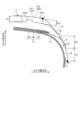
- FIG. 1 is a cross-sectional view in the tire meridian direction showing a tire according to an embodiment of the present invention.
- FIG. 2 is an enlarged cross-sectional view showing a shoulder portion of the tire shown in FIG.
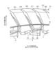
- FIG. 3 is a perspective view showing a shoulder portion of the tire shown in FIG.
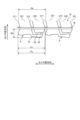
- FIG. 4 is a plan view showing a buttress portion of the tire shown in FIG.
- FIG. 5 is an explanatory diagram showing the side block shown in FIG.
- FIG. 6 is an explanatory diagram showing the side block shown in FIG.
- FIG. 7 is a table showing the results of performance tests of the tire according to the embodiment of the present invention.
- FIG. 8 is a table showing the results of performance tests of the tire according to the embodiment of the present invention.
- FIG. 1 is a cross-sectional view in the tire meridian direction showing a tire 1 according to an embodiment of the present invention.
- the figure shows a cross-sectional view of one side region in the tire radial direction.
- the figure also shows a pneumatic radial tire for a crossover SUV as an example of the tire.
- the tire meridian cross section is defined as the cross section of the tire cut by a plane including the tire rotation axis (not shown).
- the tire equatorial plane CL is defined as the plane that passes through the midpoint of the tire section width measurement points specified by JATMA and is perpendicular to the tire rotation axis.
- the tire width direction is defined as the direction parallel to the tire rotation axis, and the tire radial direction is defined as the direction perpendicular to the tire rotation axis.
- the tire 1 has an annular structure centered on the tire rotation axis, and includes a pair of bead cores 11, 11, a pair of bead fillers 12, 12, a carcass layer 13, a belt layer 14, a tread rubber 15, a pair of sidewall rubbers 16, 16, and a pair of rim cushion rubbers 17, 17 (see Figure 1).
- the pair of bead cores 11, 11 are made by winding one or more steel bead wires in a circular shape in multiple layers, and are embedded in the bead portions to form the cores of the left and right bead portions.
- the pair of bead fillers 12, 12 are respectively positioned on the outer periphery of the pair of bead cores 11, 11 in the tire radial direction to reinforce the bead portions.
- the carcass layer 13 has a single-layer structure consisting of one carcass ply or a multi-layer structure consisting of multiple carcass plies stacked together, and is toroidally stretched between the left and right bead cores 11, 11 to form the tire's framework. In addition, both ends of the carcass layer 13 are wrapped around and secured to the outside in the tire width direction so as to encase the bead cores 11 and the bead fillers 12.
- the carcass plies of the carcass layer 13 are formed by coating multiple carcass cords made of steel or organic fiber material (e.g., aramid, nylon, polyester, rayon, etc.) with coating rubber and rolling them, and have a cord angle (defined as the inclination angle of the carcass cords in the longitudinal direction relative to the tire circumferential direction) of 80 degrees or more and 100 degrees or less.
- a cord angle defined as the inclination angle of the carcass cords in the longitudinal direction relative to the tire circumferential direction
- the belt layer 14 is made by laminating multiple belt plies 141 to 144 and is arranged around the outer periphery of the carcass layer 13.
- the belt plies 141 to 144 include a pair of cross belts 141, 142 and multiple belt covers 143, 144.
- the pair of cross belts 141, 142 are made by coating multiple belt cords made of steel or organic fiber material with coating rubber and rolling them, and have a cord angle of 15 degrees or more and 55 degrees or less in absolute value.
- the pair of cross belts 141, 142 have cord angles of opposite signs (defined as the inclination angle of the belt cords in the longitudinal direction with respect to the tire circumferential direction), and are layered with the belt cords' longitudinal directions crossing each other (so-called cross-ply structure).
- the pair of cross belts 141, 142 are layered and arranged on the outer side of the carcass layer 13 in the tire radial direction.
- the belt cover 143 is made by covering a belt cover cord made of steel or organic fiber material with coating rubber, and has a cord angle of 0 degrees or more and 10 degrees or less in absolute value.
- the belt cover 143 is, for example, a strip material made by covering one or more belt cover cords with coating rubber, and is constructed by winding this strip material spirally around the outer circumferential surfaces of the cross belts 141, 142 multiple times in the tire circumferential direction.
- the belt cover 143 is disposed to cover the entire area of the cross belts 141, 142.
- the tread rubber 15 is arranged on the tire radial outer circumference of the carcass layer 13 and the belt layer 14 to form the tire tread portion.
- a pair of sidewall rubbers 16, 16 are arranged on the tire widthwise outer sides of the carcass layer 13 to form the left and right sidewall portions.
- a pair of rim cushion rubbers 17, 17 extend from the tire radial inner side of the left and right bead cores 11, 11 and the turned-up portion of the carcass layer 13 to the tire widthwise outer side to form the rim fitting surface of the bead portion.
- the tire 1 also has a plurality of circumferential main grooves 2 and a plurality of land portions 3 defined by these circumferential main grooves 2 on the tread surface.
- the tire 1 has four circumferential main grooves 2 and five rows of land portions.
- the circumferential main groove 2 is a groove that is required to display a wear indicator as stipulated by JATMA, and has a groove width of 2.5 mm to 15.0 mm and a groove depth of 8.0 mm to 12.0 mm.
- the groove width is measured as the distance between the opposing groove walls at the groove opening when the tire is mounted on a specified rim and inflated to the specified internal pressure in an unloaded state.
- the groove width is measured at the intersection of an extension of the tread surface and an extension of the groove wall in a cross-sectional view parallel to the groove width direction and groove depth direction.
- the groove depth is measured as the distance from the tread surface to the bottom of the groove when the tire is mounted on a specified rim, inflated to the specified internal pressure, and in an unloaded state. In addition, for configurations that have partial unevenness or sipes at the bottom of the groove, the groove depth is measured excluding these.
- the specified rim refers to the "standard rim” specified by JATMA, the "Design Rim” specified by TRA, or the “Measuring Rim” specified by ETRTO.
- the specified internal pressure refers to the "maximum air pressure” specified by JATMA, the maximum value of the "TIRE LOAD LIMITS AT VARIOUS COLD INFLATION PRESSURES” specified by TRA, or the “INFLATION PRESSURES" specified by ETRTO.
- the specified load refers to the "maximum load capacity" specified by JATMA, the maximum value of the "TIRE LOAD LIMITS AT VARIOUS COLD INFLATION PRESSURES" specified by TRA, or the "LOAD CAPACITY” specified by ETRTO.
- JATMA the specified internal pressure for passenger car tires is 180 kPa, and the specified load is 88% of the maximum load capacity at the specified internal pressure.
- Figures 2 and 3 are an enlarged cross-sectional view (Figure 2) and a perspective view (Figure 3) of the shoulder portion of the tire 1 shown in Figure 1.
- Figure 2 shows a cross-sectional view of the region from the shoulder main groove 2s to the tire maximum width position A of the tire 1
- Figure 3 shows a perspective view of the tire buttress portion.
- a pair of circumferential main grooves 2s, 2s located at the outermost sides in the tire width direction are defined as shoulder main grooves, and land portions 3s, 3s on the outer sides in the tire width direction defined by these shoulder main grooves 2s, 2s are defined as shoulder land portions.
- the pair of shoulder land portions 3s, 3s has tire ground contact ends T on its tread surface.
- the tire contact edge T is defined as the maximum axial width position of the contact surface between the tire and a flat plate when the tire is mounted on a specified rim, pressurized to the specified internal pressure, and placed perpendicular to a flat plate in a stationary state and subjected to a load corresponding to the specified load.
- the shoulder land portion 3s has first and second shoulder lug grooves 311, 312, and first and second shoulder blocks 321, 322 defined by these shoulder lug grooves 311, 312.
- the first and second shoulder lug grooves 311, 312 open into the shoulder main groove 2s at one end, extend in the tire width direction and intersect with the tire ground contact edge T, and have the other end in the tire buttress portion.
- the first and second shoulder lug grooves 311, 312 are arranged alternately in the tire circumferential direction.
- the first and second shoulder lug grooves 311, 312 are distinguished by their positional relationship with the side block 4, which will be described later. Therefore, the first and second shoulder lug grooves 311, 312 may have the same structure or may have structures different from each other.
- the first and second shoulder lug grooves 311, 312 have a groove width (dimension symbols omitted in the figure) of 4.0 mm or more and 9.0 mm or less and a groove depth H31 (see FIG. 2) of 6.0 mm or more and 10.5 mm or less.
- the groove depth H31 of the shoulder lug grooves 311, 312 is in the range of 0.70 ⁇ H31/Hm ⁇ 0.90 relative to the groove depth Hm of the shoulder main groove 2s (see FIG. 2). Therefore, the shoulder lug grooves 311, 312 are distinguished from sipes that are closed when the tire is in contact with the ground in that they open and function as grooves when the tire is in contact with the ground.
- the groove depth H31 of the shoulder lug grooves 311, 312 is measured as the maximum groove depth in the tire contact area when the tire is mounted on a specified rim, inflated to the specified internal pressure, and in an unloaded state.
- the first and second shoulder blocks 321, 322 extend from the shoulder main groove 2s to the tire buttress portion.
- the first and second shoulder blocks 321, 322 are arranged alternately in the tire circumferential direction to form a row of blocks.
- the first and second shoulder blocks 321, 322 are distinguished by their positional relationship with the side blocks 4, which will be described later. Therefore, the first and second shoulder blocks 321, 322 may have the same structure or may have structures different from each other.
- the first and second shoulder blocks 321, 322 may have, for example, sipes formed on the tread surface, chamfers or notches formed on the edge, and decorative shallow grooves formed on the buttress portion (not shown).
- FIG. 4 is a plan view showing the buttress portion of the tire 1 shown in FIG.
- this tire 1 has side blocks 4 in the buttress portion.
- the side blocks 4 are convex portions that protrude from the side profile of the tire to the outer surface of the tire, and have the main functions of (1) protecting the tire side portions from external damage and increasing the tire's cut resistance, and (2) improving the snow removal performance of the buttress portion and increasing the tire's snow traction performance.
- the buttress portion is defined as a non-grounded area formed at the connection between the tread profile and the sidewall profile, and constitutes the outer sidewall surface in the tire width direction of the shoulder land portion 3s.
- the side profile is the contour line that approximates the outer surface of the sidewall from the bead portion to the buttress portion as a smooth arc when viewed in cross section in the tire meridian direction, and is defined excluding the partial unevenness formed on the tire side portion (such as side block 4 and mold split position M in Figure 4).
- the tire profile is the outline of the tire in a cross-sectional view taken along the tire meridian direction, and is measured using a laser profiler.
- a tire profile measuring device manufactured by Matsuo Corporation
- Matsuo Corporation is used as the laser profiler.
- the height Hs of the side blocks 4 is in the range of 0.5 mm ⁇ Hs ⁇ 3.0 mm, and preferably in the range of 1.0 mm ⁇ Hs ⁇ 2.0 mm.
- the lower limit ensures that the side blocks 4 improve the snow performance of the tire.
- the upper limit prevents the tire from deforming freely due to the side blocks 4 being too large, and ensures the tire's ground contact characteristics.
- the maximum height Hs of the side block 4 is measured as the maximum protruding height from the side profile to the top surface of the side block 4.
- multiple side blocks 4 are arranged at a predetermined interval in the tire circumferential direction.
- multiple units each of which is a pair of one side block 4 and first and second shoulder blocks 321, 322, are arranged around the entire circumference of the tire. Therefore, the pitch length Ps of the side block 4 is equal to the pitch length Pb of the first and second shoulder blocks 321, 322. Also, the total number of side blocks 4 is half the total number of the first and second shoulder blocks 321, 322.
- the circumferential length Ls of the side block 4 is in the range of 0.80 ⁇ Ls/Pb ⁇ 1.00 relative to the pitch length Pb of the first and second shoulder blocks 321, 322, and preferably in the range of 0.85 ⁇ Ls/Pb ⁇ 0.95.
- the above lower limit ensures the circumferential length Ls of the side block 4, ensuring the snow traction performance of the side block 4.
- the above upper limit also suppresses a decrease in the degree of freedom of tire deformation caused by the circumferential length Ls of the side block 4 being excessive, ensuring the ground contact characteristics of the tire.
- the circumferential length Ls of the side block 4 is the maximum extension length in the circumferential direction of the tire of the side block 4, which is a set of a long block portion 41 and a short block portion 42 (described later), and is measured in a plan view of the buttress portion.
- the tire 1 has a mold split position M in the buttress portion, and the side block 4 extends radially inward from the mold split position M.
- the mold split position M is defined as the position corresponding to the connection of the split mold of the tire molding die.
- a rib-like protrusion with a width of about 2 to 3 mm is formed by residual rubber that is caught during tire vulcanization molding.
- the split mold (not shown) is made up of a first molding die that moves back and forth in the tire radial direction to form the tread portion, and left and right second molding dies that move back and forth in the tire axial direction to form the side portions, so that the mold split position M has a rib-like structure that extends in the tire circumferential direction.
- the mold split position M is not formed in the tire side portion, but is formed on the tread surface. In this case, the mold split position M in Figures 2 to 4 is omitted.
- the radial width Ws of the side block 4 is in the range of 0.05 ⁇ Ws/SH ⁇ 0.25 relative to the tire cross-sectional height SH (see FIG. 1), and preferably in the range of 0.10 ⁇ Ws/SH ⁇ 0.20.
- the above lower limit ensures the radial width Ws of the side block 4, ensuring the snow traction performance of the side block 4.
- the above upper limit also suppresses the reduction in the degree of freedom of tire deformation caused by the side block 4 being excessively large, ensuring the ground contact characteristics of the tire.
- the radial width Ws of the side block 4 is measured as the maximum radial extension length of the side block 4 when the tire is mounted on a specified rim, the specified internal pressure is applied, and the tire is in an unloaded state.
- the radial distance Ds from the maximum tire width position A to the radially inner end of the side block 4 is in the range of 0.05 ⁇ Ds/SH ⁇ 0.25 relative to the tire cross-sectional height SH (see FIG. 1), and preferably in the range of 0.10 ⁇ Ds/SH ⁇ 0.20.
- the above lower limit prevents a decrease in the degree of freedom of tire deformation and ensures the tire's ground contact characteristics.
- the above upper limit ensures the radial width Ws of the side block 4, ensuring the snow traction performance of the side block 4.
- FIG. 5 is an enlarged view showing one side block 4
- Fig. 6 is an enlarged view showing an L-shaped groove of the side block 4.
- the side block 4 has a long block portion 41, a short block portion 42, and an L-shaped groove 43.
- the long block portion 41 is a block portion that is long in the tire circumferential direction and is positioned so as to overlap both the first and second shoulder blocks 321, 322 when viewed in the tire radial direction (i.e., when projected onto the tire radial direction). This improves the snow traction performance of the tire compared to a configuration that has only short side blocks (not shown).
- the circumferential length L1 of the long block portion 41 is in the range of 0.60 ⁇ L1/Ls ⁇ 1.00 relative to the circumferential length Ls of the side block, and preferably in the range of 0.80 ⁇ L1/Ls ⁇ 0.90.
- the circumferential length L1 of the long block portion 41 is measured as the maximum extension length of the long block portion 41 in the tire circumferential direction.
- the radial width W1 of the long block portion 41 is in the range of 0.25 ⁇ W1/L1 ⁇ 0.45 relative to the circumferential length L1 of the long block portion 41, and preferably in the range of 0.30 ⁇ W1/L1 ⁇ 0.40. This optimizes the aspect ratio of the long block portion 41, ensuring that the long block portion 41 improves snow traction performance.
- the radial width W1 of the long block portion 41 is measured as the maximum extension length of the long block portion 41 in the tire radial direction.
- the tire 1 has a mold split position M in the buttress portion, and the radially outer edge portion of the long block portion 41 connects to the mold split position M.
- the connection length Le1 of the long block portion 41 to the mold split position M is in the range of 0.35 ⁇ Le1/L1 ⁇ 0.55 with respect to the circumferential length L1 of the long block portion 41, and preferably in the range of 0.40 ⁇ Le1/L1 ⁇ 0.50.
- connection length Le1 of the long block portion 41 is measured as the length in the tire circumferential direction along the mold split position M.
- the first shoulder block 321 extends to the mold split position M.
- the radially outer edge of the long block portion 41 is disposed opposite the radially inner edge of the first shoulder block 321 across the mold split position M.
- the connection length Le1 of the long block portion 41 at the mold split position M is in the range of 0.90 ⁇ Le1/Lb1 ⁇ 1.10 with respect to the circumferential length Lb1 of the first shoulder block 321 at the mold split position M, and is preferably in the range of 0.95 ⁇ Le1/Lb1 ⁇ 1.05.
- connection length Le1 of the long block portion 41 at the mold split position M is measured as the spacing between the first and second shoulder lug grooves 311, 312 that define the long block portion 41.
- the radially outer edge of the long block portion 41 is aligned with the radially inner edge of the first shoulder block 321 in the tire circumferential direction, so that the long block portion 41 extends the first shoulder block 321 in the tire radial direction via the mold split position M.
- the long block portion 41 has an edge shape that tapers from the mold split position M toward the tire radially inward.
- the radial groove portion 431 of the L-shaped groove 43 described below is inclined in the bending direction of the L-shaped groove 43 toward the tire radially inward, and the other circumferential edge portion of the long block portion 41 is inclined in the opposite direction to the radial groove portion 431.
- the circumferential length of the long block portion 41 is expanded from the mold split position M toward the tire radially inward. This improves the snow traction effect of the side block 4.
- the tire radial distance W1' from one end point of the measurement point of the circumferential length L1 of the long block portion 41, specifically the end point on the opposite side of the L-shaped groove 43, to the mold split position M is in the range of 0.40 ⁇ W1'/W1 ⁇ 0.70 relative to the radial width W1 of the long block portion 41, and preferably in the range of 0.50 ⁇ W1'/W1 ⁇ 0.60.
- the width Wt of the long block portion 41 at the apex Q of the bent shape of the L-shaped groove 43 described later is in the range of 0.10 ⁇ Wt/W1 with respect to the radial width W1 of the long block portion 41, and preferably in the range of 0.15 ⁇ Wt/W1. This ensures the cut resistance performance of the long block portion 41 at the tire side portion.
- the ratio Wt/W1 is subject to other conditions.
- the short block portion 42 is a block portion that is shorter in the tire circumferential direction than the long block portion 41, and is positioned so as to overlap the second shoulder block 322 and the long block portion 41 when viewed in the tire radial direction. Specifically, the short block portion 42 is positioned between the second shoulder block 322 and the long block portion 41.
- the circumferential length L2 of the short block portion 42 is in the range of 0.35 ⁇ L2/Ls ⁇ 0.55 relative to the circumferential length Ls of the side block 4, and preferably in the range of 0.40 ⁇ L2/Ls ⁇ 0.50.
- the circumferential length L2 of the short block portion 42 is in the range of 0.30 ⁇ L2/L1 ⁇ 0.60 relative to the circumferential length L1 of the long block portion 41, and preferably in the range of 0.40 ⁇ L2/L1 ⁇ 0.50.
- the above lower limit ensures the circumferential length L2 of the short block portion 42, and ensures the short block portion 42's effect of improving snow traction performance.
- the above upper limit prevents the tire's ground contact characteristics from deteriorating due to the short block portion 42 being too large.
- the circumferential length L2 of the short block portion 42 is measured as the maximum extension length of the short block portion 42 in the tire circumferential direction.
- the circumferential length L2' of the edge portion on the radially inner side of the short block portion 42 defined by the circumferential groove portion 432 described later is in the range of 0.70 ⁇ L2'/L2 ⁇ 0.90 relative to the circumferential length L2 (see FIG. 5) of the short block portion 42, and preferably in the range of 0.75 ⁇ L2'/L2 ⁇ 0.85.
- the above lower limit ensures that the short block portion 42 improves snow traction performance, and the above upper limit improves snow removal performance in the L-shaped groove 43.
- the radial width W2 of the short block portion 42 is in the range of 0.20 ⁇ W2/L2 ⁇ 0.50 relative to the circumferential length L2 of the short block portion 42, and preferably in the range of 0.30 ⁇ W2/L2 ⁇ 0.40. This optimizes the aspect ratio of the short block portion 42, ensuring the improvement of snow traction performance by the short block portion 42 and the snow removal function in the L-shaped groove 43.
- the radial width W2 of the short block portion 42 is in the range of 0.30 ⁇ W2/W1 ⁇ 0.60 relative to the radial width W1 of the long block portion 41, and preferably in the range of 0.40 ⁇ W2/W1 ⁇ 0.50. This ensures a balanced arrangement between the long block portion 41 and the short block portion 42.
- the radial width W2 of the short block portion 42 is measured as the maximum extension length of the short block portion 42 in the tire radial direction.
- the tire 1 has a mold split position M in the buttress portion, and the radially outer edge portion of the short block portion 42 connects to the mold split position M.
- the connection length Le2 of the short block portion 42 to the mold split position M is in the range of 0.80 ⁇ Le2/L2 ⁇ 1.00 with respect to the circumferential length L2 of the short block portion 42, and preferably in the range of 0.85 ⁇ Le2/L2 ⁇ 0.95.
- connection length Le2 of the short block portion 42 is measured as the length in the tire circumferential direction along the mold split position M.
- the second shoulder block 322 extends to the mold split position M.
- the radially outer edge of the short block portion 42 faces the radially inner edge of the second shoulder block 322 across the mold split position M.
- the connection length Le2 of the short block portion 42 at the mold split position M is in the range of 0.90 ⁇ Le2/Lb2 ⁇ 1.10 with respect to the circumferential length Lb2 of the second shoulder block 322 at the mold split position M, and preferably in the range of 0.95 ⁇ Le2/Lb2 ⁇ 1.05.
- connection length Le2 of the short block portion 42 at the mold split position M is measured as the spacing between the first and second shoulder lug grooves 311, 312 that define the short block portion 42.
- the radially outer edge of the short block portion 42 is aligned with the radially inner edge of the second shoulder block 322 in the tire circumferential direction, so that the short block portion 42 extends the second shoulder block 322 in the tire radial direction via the mold split position M.
- the short block portion 42 has an edge shape that tapers from the mold split position M toward the tire radially inward.
- the radial groove portion 431 of the L-shaped groove 43 described later is inclined in the bending direction of the L-shaped groove 43 toward the tire radially inward, and the other circumferential edge portion of the short block portion 42 is inclined in the opposite direction to the radial groove portion 431.
- the circumferential length of the short block portion 42 is reduced from the mold split position M toward the tire radially inward. This improves the snow removal function of the L-shaped groove 43 described later.
- the L-shaped groove 43 has an L-shape in a plan view of the buttress portion, and is a groove that penetrates the side block 4 to divide the long block portion 41 and the short block portion 42. Specifically, the L-shaped groove 43 divides the long block portion 41 at the edge portion on the reflective angle side (back side) of the L-shape, and divides the short block portion 42 at the edge portion on the apex angle side (ventral side) of the L-shape.
- This L-shaped groove 43 is formed by connecting a radial groove portion 431 and a circumferential groove portion 432 in an L shape. In this configuration, the edge components of the side block 4 in the tire circumferential direction and tire radial direction are increased by the L-shaped groove 43, improving the snow traction performance of the tire.
- the radial groove portion 431 extends in the tire radial direction and connects to the edge portion of the side block 4 on the outer side in the tire radial direction. In the configuration of FIG. 5, since the tire 1 has a mold split position M, the radial groove portion 431 extends to and terminates at the mold split position M.
- the radial groove portion 431 is disposed on an extension line of the second shoulder lug groove 312. This improves snow discharge from the second shoulder lug groove 312 to the radial groove portion 431.
- the groove width W31 of the radial groove portion 431 is in the range of 3.0 mm ⁇ W31 ⁇ 7.0 mm, and preferably in the range of 3.5 mm ⁇ W31 ⁇ 6.5 mm.
- the groove width W31' (dimension symbols omitted in the figure) of the radial groove portion 431 at the radially outer end is in the range of 0.90 ⁇ W31'/Wg ⁇ 1.10 with respect to the groove width Wg of the second shoulder lug groove 312 at the tire radially inner end, and preferably in the range of 0.95 ⁇ W31'/Wg ⁇ 1.05. This also promotes snow removal from the second shoulder lug groove 312 to the radial groove portion 431.
- the groove depth H31 (dimension symbols omitted in the figure) of the radial groove portion 431 is in the range of 0.80 ⁇ H31/Hs ⁇ 1.00 relative to the height Hs of the side block 4 (see FIG. 2), and preferably in the range of 0.85 ⁇ H31/Hs ⁇ 0.95.
- the radial groove portion 431 is inclined in the same direction as the second shoulder lug groove 312 with respect to the tire radial direction.
- the inclination angle ⁇ 31 of the radial groove portion 431 with respect to the tire radial direction is in the range of 5 [deg] ⁇ 31 ⁇ 35 [deg], and preferably in the range of 15 [deg] ⁇ 31 ⁇ 25 [deg], with the bending direction of the L-shaped groove 43 toward the tire radial inward being positive.
- the circumferential length of the long block portion 41 increases toward the tire radial inward, and conversely, the circumferential length of the short block portion 42 decreases toward the tire radial inward.
- the inclination angle ⁇ 31 of the radial groove portion 431 is measured as the angle between an imaginary line connecting both ends of the radial groove portion 431 and the tire radial direction.
- the front and rear edge portions of the side block 4 in the tire circumferential direction are inclined in the opposite direction in the tire radial direction to the radial groove portion 431 (see FIG. 6) of the L-shaped groove 43.
- the long block portion 41 tapers in width from the mold split position M toward the tire radial inside
- the short block portion 42 tapers in width from the mold split position M toward the tire radial inside.
- the inclination angle (dimension symbols omitted in the figure) of the front and rear edge portions of the side block 4 in the tire circumferential direction with respect to the tire radial direction is in the range of -35 degrees to -5 degrees, and preferably in the range of -25 degrees to -15 degrees, with the bending direction of the L-shaped groove 43 toward the tire radial inside being taken as the positive angle.
- the spacing between adjacent side blocks 4, 4 is in the range of 90% to 110% of the groove width (dimension symbol omitted in the figure; see dimension symbol Wg in FIG. 6) at the radially inner end of the first shoulder lug groove 311, and preferably in the range of 95% to 105%. This promotes snow removal from the first shoulder lug groove 311 to between the adjacent side blocks 4, 4.
- the circumferential groove portion 432 extends in the circumferential direction of the tire and opens to one edge portion of the side block 4 in the circumferential direction of the tire. This improves snow removal performance from the L-shaped groove 43.
- the circumferential groove portion 432 extends in the circumferential direction of the tire and defines the radially inner edge portion of the short block portion 42.
- the groove width W32 of the circumferential groove portion 432 is in the range of 0.45 ⁇ W32/W31 ⁇ 0.75 relative to the groove width W31 of the radial groove portion 431, and preferably in the range of 0.50 ⁇ W32/W31 ⁇ 0.70.
- the groove width W32 of the circumferential groove portion 432 is in the range of 1.0 mm ⁇ W32 ⁇ 5.0 mm, and preferably in the range of 2.0 mm ⁇ W32 ⁇ 4.0 mm. This promotes snow removal from the radial groove portion 431 to the circumferential groove portion 432.
- the groove depth H32 (dimension symbols omitted in the figure) of the circumferential groove portion 432 is in the range of 0.80 ⁇ H32/Hs ⁇ 1.00 relative to the height Hs of the side block 4 (see FIG. 2), and preferably in the range of 0.85 ⁇ H32/Hs ⁇ 0.95.
- the above lower limit ensures the groove depth H32 of the circumferential groove portion 432, ensuring the snow traction effect of the circumferential groove portion 432, and the above upper limit prevents deterioration of snow removal performance from the L-shaped groove 43 caused by the circumferential groove portion 432 being too deep.
- the circumferential groove portion 432 extends from the bending point of the L-shaped groove 43 in one direction in the tire circumferential direction, specifically, toward the short block portion 42, and opens to the circumferential edge portion of the side block 4.
- the inclination angle ⁇ 32 of the circumferential groove portion 432 with respect to the tire radial direction is in the range of 45 [deg] ⁇ ⁇ 32 ⁇ 135 [deg], preferably in the range of 65 [deg] ⁇ ⁇ 32 ⁇ 115 [deg], and more preferably in the range of 75 [deg] ⁇ ⁇ 32 ⁇ 95 [deg], with the bending direction of the L-shaped groove 43 toward the inside of the tire radial direction being positive.
- the circumferential groove portion 432 is inclined toward the outside in the tire radial direction toward the circumferential edge portion of the side block 4.
- the circumferential groove portion 432 has an edge component in the tire radial direction, thereby improving the snow traction of the tire.
- the inclination angle ⁇ 32 of the circumferential groove portion 432 is measured as the angle between an imaginary line connecting both ends of the circumferential groove portion 432 and the tire radial direction.
- the bending angle of the L-shaped groove 43 (dimension symbols omitted in the figure), i.e., the angle between the radial groove portion 431 and the circumferential groove portion 432, is in the range of 80 degrees to 120 degrees, and preferably in the range of 90 degrees to 110 degrees.
- the side block 4 only has the L-shaped groove 43 described above, but this is not limited thereto and the side block 4 may have thin shallow grooves, sipes, etc. (not shown).
- the planar shapes of the long block portion 41 and the short block portion 42 need only satisfy the above conditions.
- the radial groove portion 431 and the circumferential groove portion 432 have a linear shape, but this is not limited thereto, and at least one of the radial groove portion 431 and the circumferential groove portion 432 may have a gentle arc shape (not shown).
- the side blocks 4 are formed only on the buttress portions on the outer sides of the tire in the vehicle width direction when the tire is mounted on the vehicle.
- the side blocks 4 may be formed on the buttress portions on both the left and right sides of the tire (not shown).
- the tire 1 includes the first and second shoulder lug grooves 311, 312 that open into the tire buttress portion and are alternately arranged in the tire circumferential direction, the first and second shoulder blocks 321, 322 that are partitioned into the first and second shoulder lug grooves 311, 312 and alternately arranged in the tire circumferential direction, and the side blocks 4 formed in the tire buttress portion (see FIG. 3).
- the side blocks 4 also include long block portions 41 that are arranged to overlap the first and second shoulder blocks 321, 322 as viewed in the tire radial direction, short block portions 42 that are arranged to overlap the second shoulder blocks 322 and the long block portions 41 as viewed in the tire radial direction, and an L-shaped groove 43 that penetrates the side blocks 4 and partitions the long block portions 41 and the short block portions 42 (see FIG. 4).
- the L-shaped groove 43 is formed by connecting in an L-shape a radial groove portion 431 that extends in the tire radial direction and connects to an edge portion on the outer side in the tire radial direction of the side block 4, and a circumferential groove portion 432 that extends in the tire circumferential direction and opens to one edge portion in the tire circumferential direction of the side block 4 (see FIG. 5).
- the inclination angle ⁇ 32 (see FIG. 6) of the circumferential groove portion 432 with respect to the tire radial direction is in the range of 45° ⁇ 32 ⁇ 135°, with the bending direction of the L-shaped groove 43 toward the inside in the tire radial direction being taken as the positive direction.
- the side block 4 has a long block portion 41 that is arranged to overlap with each of the first and second shoulder blocks 321, 322 when viewed in the tire radial direction, which has the advantage of improving the snow traction performance of the tire compared to a configuration (not shown) that has only short side blocks.
- the side block 4 has an L-shaped groove 43 formed by connecting a radial groove portion 431 and a circumferential groove portion 432 in an L shape, which has the advantage of increasing the edge components of the side block 4 in the tire circumferential direction and tire radial direction, thereby improving the snow traction performance of the tire.
- the circumferential groove portion 432 opens to one edge portion of the side block 4 in the tire circumferential direction, which has the advantage of improving the snow removal performance from the L-shaped groove 43.
- the circumferential length L1 of the long block portion 41 is in the range of 0.60 ⁇ L1/Ls ⁇ 1.00 relative to the circumferential length Ls of the side block (see FIG. 5).
- the above lower limit ensures the circumferential length L1 of the long block portion 41, which has the advantage of ensuring the effect of the long block portion 41 in improving snow traction performance.
- the circumferential length Ls of the side block 4 in the tire 1 described in [2] above is in the range of 0.80 ⁇ Ls/Pb ⁇ 1.00 relative to the pitch length Pb of the first and second shoulder blocks 321, 322 (see FIG. 4).
- the lower limit ensures the circumferential length L1 of the long block portion 41, ensuring the snow traction performance improvement effect of the long block portion 41, while the upper limit has the advantage of suppressing deterioration of the tire's ground contact characteristics caused by the circumferential length Ls of the side block 4 being excessively large.
- the radial width W1 of the long block portion 41 is in the range of 0.25 ⁇ W1/L1 ⁇ 0.45 with respect to the circumferential length L1 of the long block portion 41 (see FIG. 5). This provides the advantage of optimizing the aspect ratio of the long block portion 41 and ensuring the improvement of snow traction performance by the long block portion 41.
- the circumferential length L2 of the short block portion 42 in the tire 1 described in [1] to [4] above is in the range of 0.35 ⁇ L2/Ls ⁇ 0.55 relative to the circumferential length Ls of the side block 4 (see FIG. 5).
- the lower limit ensures the circumferential length L2 of the short block portion 42, ensuring the short block portion 42's effect of improving snow traction performance, while the upper limit has the advantage of suppressing deterioration of the tire's ground contact characteristics caused by the short block portion 42 being excessively large.
- the circumferential length L2' (see FIG. 6) of the edge portion on the inner side in the tire radial direction of the short block portion 42 defined by the circumferential groove portion 432 is in the range of 0.70 ⁇ L2'/L2 ⁇ 0.90 relative to the circumferential length L2 (see FIG. 5) of the short block portion 42.
- the above lower limit ensures the short block portion 42's effect of improving snow traction performance
- the above upper limit has the advantage of improving snow removal performance in the L-shaped groove 43.
- the radial width W2 of the short block portion 42 is in the range of 0.20 ⁇ W2/L2 ⁇ 0.50 relative to the circumferential length L2 of the short block portion 42 (see FIG. 5). This optimizes the aspect ratio of the short block portion 42, which has the advantage of improving snow traction performance by the short block portion 42 and ensuring snow removal in the L-shaped groove 43.
- the radial width W2 of the short block portion 42 is in the range of 0.30 ⁇ W2/W1 ⁇ 0.60 relative to the radial width W1 of the long block portion 41 (see FIG. 5). This has the advantage of ensuring a balanced arrangement of the long block portion 41 and the short block portion 42.
- the tire 1 is the tire 1 described in [1] to [8] above, with the mold split position M in the tire buttress portion (see FIG. 5).
- the long block portion 41 has an edge shape that tapers from the mold split position M toward the tire radially inward.
- the short block portion 42 has an edge shape that tapers from the mold split position M toward the tire radially inward.
- This configuration has the advantage that the tapered shape of the long block portion 41 improves the snow traction effect of the side block 4, and the tapered shape of the short block portion 42 improves the snow removal effect in the L-shaped groove 43.
- the groove width W32 of the circumferential groove portion 432 is in the range of 0.45 ⁇ W32/W31 ⁇ 0.75 with respect to the groove width W31 of the radial groove portion 431 (see FIG. 6). This has the advantage of facilitating snow removal from the radial groove portion 431 to the circumferential groove portion 432.
- the groove depth H32 (dimension symbols omitted in the figure) of the circumferential groove portion 432 is in the range of 0.80 ⁇ H32/Hs ⁇ 1.00 relative to the height Hs of the side block 4 (see FIG. 2).
- the lower limit ensures the groove depth H32 of the circumferential groove portion 432, ensuring the snow traction effect of the circumferential groove portion 432, while the upper limit has the advantage of suppressing deterioration of snow removal performance from the L-shaped groove 43 caused by the circumferential groove portion 432 being too deep.
- the height Hs of the side blocks 4 is in the range of 0.5 mm ⁇ Hs ⁇ 3.0 mm. This has the advantage that the height Hs of the side blocks 4 is optimized.
- FIGS 7 and 8 are charts showing the results of performance tests on tires according to an embodiment of the present invention.
- test tires were evaluated for (1) snow traction performance and (2) snow removal performance.
- a test tire with tire size LT225/65R17 102H was mounted on a rim with rim size 17 x 6.5J, and an internal pressure of 230 kPa and the specified load of JATMA were applied to this test tire.
- the test tires were mounted on all wheels of a crossover SUV, which was the test vehicle.
- the test vehicle runs on a specified snowy road surface, and the test driver performs a sensory evaluation of the traction performance.
- This evaluation is performed using an index evaluation with the comparative example as the standard (100), and the higher the value, the more preferable it is.
- test tires of the comparative example and the embodiment have the configurations shown in Figs. 1 to 4 and have side blocks 4 on the buttress portion on the outer side in the vehicle width direction. Furthermore, a unit consisting of one side block 4 and a pair of shoulder blocks 321, 322 is arranged around the entire circumference of the tire. Furthermore, the side block 4 has an L-shaped groove 43 that divides the long block portion 41 and the short block portion 42.
- the tire cross-sectional height SH is 142.2 mm
- the pitch length Pb of the shoulder blocks 321, 322 and the pitch length Ps of the side block 4 are equal and are 59.1 mm on average in the tire circumferential direction
- the height Hs of the side block 4 is 1.5 mm
- the groove width W32 of the radial groove portion 431 of the side block 4 is in the range of 4.5 mm to 6.0 mm.
- test tire of the embodiment can improve the snow traction performance of the tire while maintaining the snow removal performance of the side block grooves.
Landscapes
- Engineering & Computer Science (AREA)
- Mechanical Engineering (AREA)
- Tires In General (AREA)
Abstract
このタイヤでは、サイドブロック4が、タイヤ径方向視にて第一および第二のショルダーブロックのそれぞれに対してオーバーラップして配置された長尺ブロック部41と、タイヤ径方向視にて第二ショルダーブロック322および長尺ブロック部41のそれぞれに対してオーバーラップして配置された短尺ブロック部42と、サイドブロック4を貫通して長尺ブロック部41および短尺ブロック部42を区画するL字溝43とを備える。また、L字溝43が、径方向溝部431と周方向溝部432とをL字状に接続して成る。また、タイヤ径方向に対する周方向溝部432の傾斜角θ32が、45°≦θ32≦135°の範囲にある。
Description
この発明は、タイヤに関し、さらに詳しくは、スノートラクション性能を向上できるタイヤに関する。
近年のクロスオーバーSUV(Sport Utility Vehicle)用タイヤでは、タイヤのスノートラクション性能を向上するために、溝を有するサイドブロックをタイヤのバットレス部に備えている。かかる構造を採用する従来のタイヤとして、特許文献1に記載される技術が知られている。
この発明は、上記に鑑みてなされたものであって、スノートラクション性能を向上できるタイヤを提供することを目的とする。
上記目的を達成するため、この発明にかかるタイヤは、タイヤバットレス部に開口すると共にタイヤ周方向に交互に配列された第一および第二のショルダーラグ溝と、前記第一および第二のショルダーラグ溝に区画されると共にタイヤ周方向に交互に配列された第一および第二のショルダーブロックと、タイヤバットレス部に形成されたサイドブロックとを備えるタイヤであって、前記サイドブロックが、タイヤ径方向視にて前記第一および第二のショルダーブロックのそれぞれに対してオーバーラップして配置された長尺ブロックと、タイヤ径方向視にて前記第二ショルダーブロックおよび前記長尺ブロック部のそれぞれに対してオーバーラップして配置された短尺ブロックと、前記サイドブロックを貫通して前記長尺ブロック部および前記短尺ブロック部を区画するL字溝とを備え、前記L字溝が、タイヤ径方向に延在して前記サイドブロックのタイヤ径方向外側のエッジ部に接続する径方向溝部と、タイヤ周方向に延在して前記サイドブロックのタイヤ周方向の一方のエッジ部に開口する周方向溝部とをL字状に接続して成り、且つ、タイヤ径方向に対する前記周方向溝部の傾斜角θ32が、タイヤ径方向内側に向かって前記L字溝の屈曲方向を正として、45°≦θ32≦135°の範囲にあることを特徴とする。
この発明にかかるタイヤでは、(1)サイドブロックが、タイヤ径方向視にて第一および第二のショルダーブロックのそれぞれに対してオーバーラップして配置された長尺ブロック部を備えるので、短尺なサイドブロックのみを備える構成と比較して、タイヤのスノートラクション性能が向上する利点がある。また、(2)サイドブロックが、径方向溝部と周方向溝部とをL字状に接続して成るL字溝を備えるので、タイヤ周方向およびタイヤ径方向に対するサイドブロックのエッジ成分が増加して、タイヤのスノートラクション性能が向上する利点がある。さらに、(3)周方向溝部が、サイドブロックのタイヤ周方向の一方のエッジ部に開口するので、L字溝からの排雪性能が向上する利点がある。
以下、この発明につき図面を参照しつつ詳細に説明する。なお、この実施の形態によりこの発明が限定されるものではない。また、この実施の形態の構成要素には、発明の同一性を維持しつつ置換可能かつ置換自明なものが含まれる。また、この実施の形態に記載された複数の変形例は、当業者自明の範囲内にて任意に組み合わせが可能である。
[タイヤ]
図1は、この発明の実施の形態にかかるタイヤ1を示すタイヤ子午線方向の断面図である。同図は、タイヤ径方向の片側領域の断面図を示している。また、同図は、タイヤの一例として、クロスオーバーSUV用の空気入りラジアルタイヤを示している。
図1は、この発明の実施の形態にかかるタイヤ1を示すタイヤ子午線方向の断面図である。同図は、タイヤ径方向の片側領域の断面図を示している。また、同図は、タイヤの一例として、クロスオーバーSUV用の空気入りラジアルタイヤを示している。
同図において、タイヤ子午線方向の断面は、タイヤ回転軸(図示省略)を含む平面でタイヤを切断したときの断面として定義される。また、タイヤ赤道面CLは、JATMAに規定されたタイヤ断面幅の測定点の中点を通りタイヤ回転軸に垂直な平面として定義される。また、タイヤ幅方向は、タイヤ回転軸に平行な方向として定義され、タイヤ径方向は、タイヤ回転軸に垂直な方向として定義される。
タイヤ1は、タイヤ回転軸を中心とする環状構造を有し、一対のビードコア11、11と、一対のビードフィラー12、12と、カーカス層13と、ベルト層14と、トレッドゴム15と、一対のサイドウォールゴム16、16と、一対のリムクッションゴム17、17とを備える(図1参照)。
一対のビードコア11、11は、スチールから成る1本あるいは複数本のビードワイヤを環状かつ多重に巻き廻して成り、ビード部に埋設されて左右のビード部のコアを構成する。一対のビードフィラー12、12は、一対のビードコア11、11のタイヤ径方向外周にそれぞれ配置されてビード部を補強する。
カーカス層13は、1枚のカーカスプライから成る単層構造あるいは複数枚のカーカスプライを積層して成る多層構造を有し、左右のビードコア11、11間にトロイダル状に架け渡されてタイヤの骨格を構成する。また、カーカス層13の両端部は、ビードコア11およびビードフィラー12を包み込むようにタイヤ幅方向外側に巻き返されて係止される。また、カーカス層13のカーカスプライは、スチールあるいは有機繊維材(例えば、アラミド、ナイロン、ポリエステル、レーヨンなど)から成る複数のカーカスコードをコートゴムで被覆して圧延加工して構成され、80[deg]以上100[deg]以下のコード角度(タイヤ周方向に対するカーカスコードの長手方向の傾斜角として定義される。)を有する。
ベルト層14は、複数のベルトプライ141~144を積層して成り、カーカス層13の外周に掛け廻されて配置される。ベルトプライ141~144は、一対の交差ベルト141、142と、複数のベルトカバー143、144とを含む。
一対の交差ベルト141、142は、スチールあるいは有機繊維材から成る複数のベルトコードをコートゴムで被覆して圧延加工して構成され、絶対値で15[deg]以上55[deg]以下のコード角度を有する。また、一対の交差ベルト141、142は、相互に異符号のコード角度(タイヤ周方向に対するベルトコードの長手方向の傾斜角として定義される)を有し、ベルトコードの長手方向を相互に交差させて積層される(いわゆるクロスプライ構造)。また、一対の交差ベルト141、142は、カーカス層13のタイヤ径方向外側に積層されて配置される。
ベルトカバー143、スチールあるいは有機繊維材から成るベルトカバーコードをコートゴムで被覆して構成され、絶対値で0[deg]以上10[deg]以下のコード角度を有する。また、ベルトカバー143は、例えば、1本あるいは複数本のベルトカバーコードをコートゴムで被覆して成るストリップ材であり、このストリップ材を交差ベルト141、142の外周面に対してタイヤ周方向に複数回かつ螺旋状に巻き付けて構成される。また、ベルトカバー143が交差ベルト141、142の全域を覆って配置される。
トレッドゴム15は、カーカス層13およびベルト層14のタイヤ径方向外周に配置されてタイヤのトレッド部を構成する。一対のサイドウォールゴム16、16は、カーカス層13のタイヤ幅方向外側にそれぞれ配置されて左右のサイドウォール部を構成する。一対のリムクッションゴム17、17は、左右のビードコア11、11およびカーカス層13の巻き返し部のタイヤ径方向内側からタイヤ幅方向外側に延在して、ビード部のリム嵌合面を構成する。
また、タイヤ1は、複数の周方向主溝2と、これらの周方向主溝2に区画された複数の陸部3とをトレッド面に備える。図1の構成では、タイヤ1が、4本の周方向主溝2と、5列の陸部とを備えている。
周方向主溝2は、JATMAに規定されるウェアインジケータの表示義務を有する溝であり、2.5[mm]以上15.0[mm]以下の溝幅および8.0[mm]以上12.0[mm]以下の溝深さを有する。
溝幅は、タイヤを規定リムに装着して規定内圧を充填した無負荷状態にて、溝開口部における対向する溝壁間の距離として測定される。切欠部あるいは面取部を溝開口部に有する構成では、溝幅方向かつ溝深さ方向に平行な断面視におけるトレッド踏面の延長線と溝壁の延長線との交点を測定点として、溝幅が測定される。
溝深さは、タイヤを規定リムに装着して規定内圧を充填した無負荷状態にて、トレッド踏面から溝底までの距離として測定される。また、部分的な凹凸部やサイプを溝底に有する構成では、これらを除外して溝深さが測定される。
規定リムとは、JATMAに規定される「標準リム」、TRAに規定される「Design Rim」、あるいはETRTOに規定される「Measuring Rim」をいう。また、規定内圧とは、JATMAに規定される「最高空気圧」、TRAに規定される「TIRE LOAD LIMITS AT VARIOUS COLD INFLATION PRESSURES」の最大値、あるいはETRTOに規定される「INFLATION PRESSURES」をいう。また、規定荷重とは、JATMAに規定される「最大負荷能力」、TRAに規定される「TIRE LOAD LIMITS AT VARIOUS COLD INFLATION PRESSURES」の最大値、あるいはETRTOに規定される「LOAD CAPACITY」をいう。ただし、JATMAにおいて、乗用車用タイヤの場合には、規定内圧が空気圧180[kPa]であり、規定荷重が規定内圧での最大負荷能力の88[%]である。
[ショルダー陸部]
図2および図3は、図1に記載したタイヤ1のショルダー部を示す拡大断面図(図2)および斜視図(図3)である。これらの図において、図2は、タイヤ1のショルダー主溝2sからタイヤ最大幅位置Aまでの領域の断面図を示し、図3は、タイヤバットレス部の斜視図を示している。
図2および図3は、図1に記載したタイヤ1のショルダー部を示す拡大断面図(図2)および斜視図(図3)である。これらの図において、図2は、タイヤ1のショルダー主溝2sからタイヤ最大幅位置Aまでの領域の断面図を示し、図3は、タイヤバットレス部の斜視図を示している。
図1において、タイヤ幅方向の最外側にある一対の周方向主溝2s、2sをショルダー主溝として定義し、これらのショルダー主溝2s、2sに区画されたタイヤ幅方向外側の陸部3s、3sをショルダー陸部として定義する。一対のショルダー陸部3s、3sは、その踏面にタイヤ接地端Tを有する。
タイヤ接地端Tは、タイヤを規定リムに装着して規定内圧を付与すると共に静止状態にて平板に対して垂直に置いて規定荷重に対応する負荷を加えたときのタイヤと平板との接触面におけるタイヤ軸方向の最大幅位置として定義される。
図2および図3に示すように、ショルダー陸部3sは、第一および第二のショルダーラグ溝311、312と、これらのショルダーラグ溝311、312に区画されて成る第一および第二のショルダーブロック321、322とを備える。
第一および第二のショルダーラグ溝311、312は、一方の端部にてショルダー主溝2sに開口し、タイヤ幅方向に延在してタイヤ接地端Tに交差し、他方の端部をタイヤバットレス部に有する。また、第一および第二のショルダーラグ溝311、312が、タイヤ周方向に交互に配列される。また、第一および第二のショルダーラグ溝311、312は、後述するサイドブロック4との位置関係により区別される。したがって、第一および第二のショルダーラグ溝311、312が同一構造を有しても良いし、相互に異なる構造を有しても良い。
また、第一および第二のショルダーラグ溝311、312が、4.0[mm]以上9.0[mm]以下の溝幅(図中の寸法記号省略)および6.0[mm]以上10.5[mm]以下の溝深さH31(図2参照)を有する。また、ショルダーラグ溝311、312の溝深さH31が、ショルダー主溝2sの溝深さHm(図2参照)に対して0.70≦H31/Hm≦0・90の範囲にある。したがって、ショルダーラグ溝311、312は、タイヤ接地時に開口して溝として機能する点で、タイヤ接地時に閉塞するサイプに対して区別される。
ショルダーラグ溝311、312の溝深さH31は、タイヤを規定リムに装着して規定内圧を充填した無負荷状態にて、タイヤ接地領域における最大溝深さとして測定される。
第一および第二のショルダーブロック321、322は、ショルダー主溝2sからタイヤバットレス部まで延在する。また、第一および第二のショルダーブロック321、322が、タイヤ周方向に交互に配列されて、一列のブロック列を形成する。また、第一および第二のショルダーブロック321、322は、後述するサイドブロック4との位置関係により区別される。したがって、第一および第二のショルダーブロック321、322が同一構造を有しても良いし、相互に異なる構造を有しても良い。
なお、第一および第二のショルダーブロック321、322が、例えば、踏面に形成されたサイプ、エッジ部に形成された面取部あるいは切欠部、バットレス部に形成された装飾用の浅溝などを有しても良い(図示省略)。
[サイドブロック]
図4は、図3に記載したタイヤ1のバットレス部を示す平面図である。
図4は、図3に記載したタイヤ1のバットレス部を示す平面図である。
このタイヤ1は、図2および図3に示すように、サイドブロック4をバットレス部に備える。サイドブロック4は、タイヤのサイドプロファイルからタイヤ外面に突出した凸部であり、主として(1)タイヤサイド部を外傷から保護してタイヤの耐カット性を高める機能および(2)バットレス部の排雪性を向上してタイヤのスノートラクション性能を高める機能を有する。
バットレス部は、トレッド部のプロファイルと、サイドウォール部のプロファイルとの接続部に形成された非接地領域として定義され、ショルダー陸部3sのタイヤ幅方向外側の側壁面を構成する。
サイドプロファイルは、タイヤ子午線方向の断面視にてビード部からバットレス部に至るサイドウォールの外面を滑らかな円弧で近似した輪郭線であり、タイヤサイド部に形成された部分的な凹凸部(図4では、サイドブロック4およびモールドの割り位置Mなど)を除外して定義される。
タイヤのプロファイルは、タイヤ子午線方向の断面視におけるタイヤの輪郭線であり、レーザープロファイラを用いて計測される。レーザープロファイラとしては、例えば、タイヤプロファイル測定装置(株式会社マツオ製)が使用される。
また、図2において、サイドブロック4の高さHsが、0.5[mm]≦Hs≦3.0[mm]の範囲にあり、好ましくは1.0[mm]≦Hs≦2.0[mm]の範囲にある。上記下限により、上記したサイドブロック4によるタイヤのスノー性能の向上作用が確保される。上記上限により、サイドブロック4が過大となることに起因するタイヤ変形の自由度の低下が抑制されて、タイヤの接地特性が確保される。
サイドブロック4の最大高さHsは、サイドプロファイルからサイドブロック4の頂面までの突出高さの最大値として測定される。
また、図4に示すように、複数のサイドブロック4が、タイヤ周方向に所定間隔で配列される。例えば、図4の構成では、1つのサイドブロック4と第一および第二のショルダーブロック321、322とを一組とする複数のユニットが、タイヤ全周に渡って配列される。このため、サイドブロック4のピッチ長Psが、第一および第二のショルダーブロック321、322のピッチ長Pbに等しい。また、サイドブロック4の総数が、第一および第二のショルダーブロック321、322の総数の半分である。
また、図4において、サイドブロック4の周方向長さLsが、第一および第二のショルダーブロック321、322のピッチ長Pbに対して0.80≦Ls/Pb≦1.00の範囲にあり、好ましくは0.85≦Ls/Pb≦0.95の範囲にある。上記下限により、サイドブロック4の周方向長さLsが確保されて、サイドブロック4によるスノートラクション性能が確保される。また、上記上限により、サイドブロック4の周方向長さLsが過大となることに起因するタイヤ変形の自由度の低下が抑制されて、タイヤの接地特性が確保される。
サイドブロック4の周方向長さLsは、後述する長尺ブロック部41および短尺ブロック部42を一組とするサイドブロック4のタイヤ周方向への延在長さの最大値であり、バットレス部の平面視にて測定される。
また、図2~図4に示すように、タイヤ1がモールドの割り位置Mをバットレス部に有し、サイドブロック4が、モールドの割り位置Mからタイヤ径方向内側に延在する。
モールドの割り位置Mは、タイヤ成形金型の分割モールドの接続部に対応する位置として定義される。このモールドの割り位置Mには、タイヤ加硫成型時に噛み込んだ残留ゴムにより、2[mm]~3[mm]程度の幅を有するリブ状の突起が形成される。具体的に、分割モールド(図示省略)がタイヤ径方向に進退してトレッド部を形成する第一成形金型とタイヤ軸方向に進退してサイド部を形成する左右の第二成形金型とから成ることにより、モールドの割り位置Mが、タイヤ周方向に延在するリブ状構造を有する。
しかし、これに限らず、タイヤ成形金型の分割モールドがタイヤ幅方向に二分割される構成(図示省略)では、モールドの割り位置Mがタイヤサイド部に形成されずに、トレッド面に形成される。この場合には、図2~図4のモールドの割り位置Mが省略される。
また、図2および図4において、サイドブロック4の径方向幅Wsが、タイヤ断面高さSH(図1参照)に対して0.05≦Ws/SH≦0.25の範囲にあり、好ましくは0.10≦Ws/SH≦0.20の範囲にある。上記下限により、サイドブロック4の径方向幅Wsが確保されて、サイドブロック4によるスノートラクション性能が確保される。また、上記上限により、サイドブロック4が過大となることに起因するタイヤ変形の自由度の低下が抑制されて、タイヤの接地特性が確保される。
サイドブロック4の径方向幅Wsは、タイヤを規定リムに装着して規定内圧を付与すると共に無負荷状態としたときの、サイドブロック4のタイヤ径方向への延在長さの最大値として測定される。
また、図2において、タイヤ最大幅位置Aからサイドブロック4の径方向内側端部までの径方向距離Dsが、タイヤ断面高さSH(図1参照)に対して0.05≦Ds/SH≦0.25の範囲にあり、好ましくは0.10≦Ds/SH≦0.20の範囲にある。上記下限により、タイヤ変形の自由度の低下が抑制されて、タイヤの接地特性が確保される。上記上限により、サイドブロック4の径方向幅Wsが確保されて、サイドブロック4によるスノートラクション性能が確保される。
[長尺ブロック部、短尺ブロック部およびL字溝]
図5および図6は、図4に記載した記載したサイドブロック4を示す説明図である。これらの図において、図5は、1つのサイドブロック4を示す拡大図であり、図6は、サイドブロック4のL字溝を示す拡大図である。
図5および図6は、図4に記載した記載したサイドブロック4を示す説明図である。これらの図において、図5は、1つのサイドブロック4を示す拡大図であり、図6は、サイドブロック4のL字溝を示す拡大図である。
図5に示すように、サイドブロック4は、長尺ブロック部41と、短尺ブロック部42と、L字溝43とを備える。
長尺ブロック部41は、タイヤ周方向に長尺なブロック部であり、タイヤ径方向視(すなわちタイヤ径方向への投影視)にて、第一および第二のショルダーブロック321、322の双方に対してオーバーラップして配置される。これにより、短尺なサイドブロックのみを備える構成(図示省略)と比較して、タイヤのスノートラクション性能が向上する。
また、長尺ブロック部41の周方向長さL1が、サイドブロックの周方向長さLsに対して0.60≦L1/Ls≦1.00の範囲にあり、好ましくは0.80≦L1/Ls≦0.90の範囲にある。
長尺ブロック部41の周方向長さL1は、タイヤ周方向における長尺ブロック部41の延在長さの最大値として測定される。
また、長尺ブロック部41の径方向幅W1が、長尺ブロック部41の周方向長さL1に対して0.25≦W1/L1≦0.45の範囲にあり、好ましくは0.30≦W1/L1≦0.40の範囲にある。これにより、長尺ブロック部41のアスペクト比が適正化されて、長尺ブロック部41によるスノートラクション性能の向上作用が確保される。
長尺ブロック部41の径方向幅W1は、タイヤ径方向における長尺ブロック部41の延在長さの最大値として測定される。
また、図5の構成では、タイヤ1がモールドの割り位置Mをバットレス部に備え、長尺ブロック部41の径方向外側のエッジ部がモールドの割り位置Mに接続する。このとき、モールドの割り位置Mに対する長尺ブロック部41の接続長さLe1が、長尺ブロック部41の周方向長さL1に対して0.35≦Le1/L1≦0.55の範囲にあり、好ましくは0.40≦Le1/L1≦0.50の範囲にある。
長尺ブロック部41の接続長さLe1は、モールドの割り位置Mに沿ったタイヤ周方向の長さとして測定される。
また、図5の構成では、第一ショルダーブロック321がモールドの割り位置Mまで延在する。また、長尺ブロック部41の径方向外側のエッジ部が、モールドの割り位置Mを挟んで第一ショルダーブロック321の径方向内側のエッジ部に対向して配置される。また、モールドの割り位置Mにおける長尺ブロック部41の接続長さLe1が、モールドの割り位置Mにおける第一ショルダーブロック321の周方向長さLb1に対して0.90≦Le1/Lb1≦1.10の範囲にあり、好ましくは0.95≦Le1/Lb1≦1.05の範囲にある。
モールドの割り位置Mにおける長尺ブロック部41の接続長さLe1は、長尺ブロック部41を区画する第一および第二のショルダーラグ溝311、312の配置間隔として計測される。
例えば、図5の構成では、長尺ブロック部41の径方向外側のエッジ部が、第一ショルダーブロック321の径方向内側のエッジ部に対してタイヤ周方向の位置を揃えて配置されることにより、長尺ブロック部41がモールドの割り位置Mを介して第一ショルダーブロック321をタイヤ径方向に延長している。
また、図5に示すように、長尺ブロック部41がモールドの割り位置Mからタイヤ径方向内側に向かってテーパ状に拡幅したエッジ形状を有する。具体的には、後述するL字溝43の径方向溝部431がタイヤ径方向内側に向かってL字溝43の屈曲方向に傾斜し、長尺ブロック部41の他方の周方向エッジ部が径方向溝部431に対して逆方向に傾斜する。これにより、長尺ブロック部41の周方向長さが、モールドの割り位置Mからタイヤ径方向内側に向かって拡大されている。これにより、サイドブロック4によるスノートラクション作用が向上する。
また、図5において、長尺ブロック部41の周方向長さL1の測定点における一方の端点、具体的にはL字溝43に対して逆側にある端点からモールドの割り位置Mまでのタイヤ径方向の距離W1’が、長尺ブロック部41の径方向幅W1に対して0.40≦W1’/W1≦0.70の範囲にあり、好ましくは0.50≦W1’/W1≦0.60の範囲にある。
また、図6において、後述するL字溝43の屈曲形状の頂点Qにおける長尺ブロック部41の幅Wtが、長尺ブロック部41の径方向幅W1に対して0.10≦Wt/W1の範囲にあり、好ましくは0.15≦Wt/W1の範囲にある。これにより、長尺ブロック部41によるタイヤサイド部の対カット性能が確保される。なお、比Wt/W1の上限は特に限定がないが、他の条件により制約を受ける。
短尺ブロック部42は、図5に示すように、長尺ブロック部41と比較してタイヤ周方向に短尺なブロック部であり、タイヤ径方向視にて第二ショルダーブロック322および長尺ブロック部41に対してオーバーラップして配置される。具体的には、短尺ブロック部42が、第二ショルダーブロック322と長尺ブロック部41との間に配置される。
また、短尺ブロック部42の周方向長さL2が、サイドブロック4の周方向長さLsに対して0.35≦L2/Ls≦0.55の範囲にあり、好ましくは0.40≦L2/Ls≦0.50の範囲にある。また、短尺ブロック部42の周方向長さL2が、長尺ブロック部41の周方向長さL1に対して0.30≦L2/L1≦0.60の範囲にあり、好ましくは0.40≦L2/L1≦0.50の範囲にある。上記下限により、短尺ブロック部42の周方向長さL2が確保されて、短尺ブロック部42によるスノートラクション性能の向上作用が確保される。上記上限により、短尺ブロック部42が過大となることに起因するタイヤの接地特性の悪化が抑制される。
短尺ブロック部42の周方向長さL2は、タイヤ周方向における短尺ブロック部42の延在長さの最大値として測定される。
また、図6において、後述する周方向溝部432に区画された短尺ブロック部42のタイヤ径方向内側のエッジ部の周方向長さL2’が、短尺ブロック部42の周方向長さL2(図5参照)に対して0.70≦L2’/L2≦0.90の範囲にあり、好ましくは0.75≦L2’/L2≦0.85の範囲にある。上記下限により、短尺ブロック部42によるスノートラクション性能の向上作用が確保され、上記上限により、L字溝43における排雪性能が向上する。
また、短尺ブロック部42の径方向幅W2が、短尺ブロック部42の周方向長さL2に対して0.20≦W2/L2≦0.50の範囲にあり、好ましくは0.30≦W2/L2≦0.40の範囲にある。これにより、短尺ブロック部42のアスペクト比が適正化されて、短尺ブロック部42によるスノートラクション性能の向上作用およびL字溝43における排雪作用が確保される。また、短尺ブロック部42の径方向幅W2が、長尺ブロック部41の径方向幅W1に対して0.30≦W2/W1≦0.60の範囲にあり、好ましくは0.40≦W2/W1≦0.50の範囲にある。これにより、長尺ブロック部41と短尺ブロック部42との配置バランスが確保される。
短尺ブロック部42の径方向幅W2は、タイヤ径方向における短尺ブロック部42の延在長さの最大値として測定される。
また、図5の構成では、タイヤ1がモールドの割り位置Mをバットレス部に備え、短尺ブロック部42の径方向外側のエッジ部がモールドの割り位置Mに接続する。このとき、モールドの割り位置Mに対する短尺ブロック部42の接続長さLe2が、短尺ブロック部42の周方向長さL2に対して0.80≦Le2/L2≦1.00の範囲にあり、好ましくは0.85≦Le2/L2≦0.95の範囲にある。
短尺ブロック部42の接続長さLe2は、モールドの割り位置Mに沿ったタイヤ周方向の長さとして測定される。
また、図5の構成では、第二ショルダーブロック322がモールドの割り位置Mまで延在する。また、短尺ブロック部42の径方向外側のエッジ部が、モールドの割り位置Mを挟んで第二ショルダーブロック322の径方向内側のエッジ部に対向して配置される。また、モールドの割り位置Mにおける短尺ブロック部42の接続長さLe2が、モールドの割り位置Mにおける第二ショルダーブロック322の周方向長さLb2に対して0.90≦Le2/Lb2≦1.10の範囲にあり、好ましくは0.95≦Le2/Lb2≦1.05の範囲にある。
モールドの割り位置Mにおける短尺ブロック部42の接続長さLe2は、短尺ブロック部42を区画する第一および第二のショルダーラグ溝311、312の配置間隔として計測される。
例えば、図5の構成では、短尺ブロック部42の径方向外側のエッジ部が、第二ショルダーブロック322の径方向内側のエッジ部に対してタイヤ周方向の位置を揃えて配置されることにより、短尺ブロック部42がモールドの割り位置Mを介して第二ショルダーブロック322をタイヤ径方向に延長している。
また、図5に示すように、短尺ブロック部42がモールドの割り位置Mからタイヤ径方向内側に向かってテーパ状に縮幅したエッジ形状を有する。具体的には、後述するL字溝43の径方向溝部431がタイヤ径方向内側に向かってL字溝43の屈曲方向に傾斜し、短尺ブロック部42の他方の周方向エッジ部が径方向溝部431に対して逆方向に傾斜する。これにより、短尺ブロック部42の周方向長さが、モールドの割り位置Mからタイヤ径方向内側に向かって縮小されている。これにより、後述するL字溝43における排雪作用が向上する。
L字溝43は、図5に示すように、バットレス部の平面視にてL字形状を有し、サイドブロック4を貫通して長尺ブロック部41および短尺ブロック部42を区画する溝である。具体的には、L字溝43が、L字形状の反射角側(背側)のエッジ部にて長尺ブロック部41を区画し、L字形状の頂角側(腹側)のエッジ部にて短尺ブロック部42を区画する。このL字溝43は、径方向溝部431と周方向溝部432とをL字状に接続して成る。かかる構成では、タイヤ周方向およびタイヤ径方向に対するサイドブロック4のエッジ成分がL字溝43により増加して、タイヤのスノートラクション性能が向上する。
径方向溝部431は、タイヤ径方向に延在してサイドブロック4のタイヤ径方向外側のエッジ部に接続する。図5の構成では、タイヤ1がモールドの割り位置Mを有するため、径方向溝部431がモールドの割り位置Mまで延在して終端している。
また、図5および図6に示すように、径方向溝部431が、第二ショルダーラグ溝312の延長線上に配置される。これにより、第二ショルダーラグ溝312から径方向溝部431への排雪性が向上する。
また、図6において、径方向溝部431の溝幅W31が、3.0[mm]≦W31≦7.0[mm]の範囲にあり、好ましくは3.5[mm]≦W31≦6.5[mm]の範囲にある。また、径方向外側の端部における径方向溝部431の溝幅W31’(図中の寸法記号省略)が、第二ショルダーラグ溝312のタイヤ径方向内側の端部における溝幅Wgに対して0.90≦W31’/Wg≦1.10の範囲にあり、好ましくは0.95≦W31’/Wg≦1.05の範囲にある。また、これにより、第二ショルダーラグ溝312から径方向溝部431への排雪性が促進される。
また、径方向溝部431の溝深さH31(図中の寸法記号省略)が、サイドブロック4の高さHs(図2参照)に対して0.80≦H31/Hs≦1.00の範囲にあり、好ましくは0.85≦H31/Hs≦0.95の範囲にある。
また、図6に示すように、径方向溝部431が、タイヤ径方向に対して第二ショルダーラグ溝312と同一方向に傾斜する。また、径方向溝部431のタイヤ径方向に対する傾斜角θ31が、タイヤ径方向内側に向かってL字溝43の屈曲方向を正として、5[deg]≦θ31≦35[deg]の範囲にあり、好ましくは15[deg]≦θ31≦25[deg]の範囲にある。これにより、図5に示すように、径方向溝部431の延在範囲にて、長尺ブロック部41の周方向長さがタイヤ径方向内側に向かって増加し、逆に短尺ブロック部42の周方向長さがタイヤ径方向内側に向かって減少する。
径方向溝部431の傾斜角θ31は、径方向溝部431の両端部を接続した仮想直線とタイヤ径方向との成す角度として測定される。
また、図4において、サイドブロック4のタイヤ周方向の前後のエッジ部が、L字溝43の径方向溝部431(図6参照)に対してタイヤ径方向で逆方向に傾斜する。これにより、長尺ブロック部41がモールドの割り位置Mからタイヤ径方向内側に向かってテーパ状に拡幅し、また、短尺ブロック部42がモールドの割り位置Mからタイヤ径方向内側に向かってテーパ状に縮幅する。また、サイドブロック4のタイヤ周方向の前後のエッジ部のタイヤ径方向に対する傾斜角(図中の寸法記号の省略)が、タイヤ径方向内側に向かってL字溝43の屈曲方向を正として、-35[deg]以上-5[deg]以下の範囲にあり、好ましくは-25[deg]以上-15[deg]以下の範囲にある。
なお、図4において、隣り合うサイドブロック4、4の配置間隔は、第一ショルダーラグ溝311のタイヤ径方向内側の端部における溝幅(図中の寸法記号省略;図6の寸法記号Wgを参照)に対して90[%]以上110[%]以下の範囲にあり、好ましくは95[%]以上105[%]以下の範囲にある。これにより、第一ショルダーラグ溝311から隣り合うサイドブロック4、4の間への排雪性が促進される。
周方向溝部432は、図5に示すように、タイヤ周方向に延在してサイドブロック4のタイヤ周方向の一方のエッジ部に開口する。これにより、L字溝43からの排雪性能が向上する。図5の構成では、周方向溝部432が、タイヤ周方向に延在して短尺ブロック部42の径方向内側のエッジ部を区画している。
また、図6において、周方向溝部432の溝幅W32が、径方向溝部431の溝幅W31に対して0.45≦W32/W31≦0.75の範囲にあり、好ましくは0.50≦W32/W31≦0.70の範囲にある。また、周方向溝部432の溝幅W32が、1.0[mm]≦W32≦5.0[mm]の範囲にあり、好ましくは2.0[mm]≦W32≦4.0[mm]の範囲にある。これにより、径方向溝部431から周方向溝部432への排雪性が促進される。
また、周方向溝部432の溝深さH32(図中の寸法記号省略)が、サイドブロック4の高さHs(図2参照)に対して0.80≦H32/Hs≦1.00の範囲にあり、好ましくは0.85≦H32/Hs≦0.95の範囲にある。上記下限により、周方向溝部432の溝深さH32が確保されて、周方向溝部432によるスノートラクション作用が確保され、上記上限により、周方向溝部432が深すぎることに起因するL字溝43からの排雪性能の悪化が抑制される。
また、図6に示すように、周方向溝部432が、L字溝43の屈曲点からタイヤ周方向の一方向、具体的には、短尺ブロック部42側に延在して、サイドブロック4の周方向エッジ部に開口する。このとき、タイヤ径方向に対する周方向溝部432の傾斜角θ32が、タイヤ径方向内側に向かってL字溝43の屈曲方向を正として、45[deg]≦θ32≦135[deg]の範囲にあり、好ましくは65[deg]≦θ32≦115[deg]の範囲にあり、より好ましく75[deg]≦θ32≦95[deg]の範囲にある。また、図6の構成では、90[deg]<θ32であり、周方向溝部432が、サイドブロック4の周方向エッジ部に向かってタイヤ径方向外側に傾斜している。かかる構成では、周方向溝部432がタイヤ径方向へのエッジ成分を有することにより、タイヤのスノートラクション性が向上する。
周方向溝部432の傾斜角θ32は、周方向溝部432の両端部を接続した仮想直線とタイヤ径方向との成す角度として測定される。
また、図6において、L字溝43の屈曲角(図中の寸法記号省略)、すなわち径方向溝部431と周方向溝部432とのなす角度が、80[deg]以上120[deg]以下の範囲にあり、好ましくは90[deg]以上110[deg]以下の範囲にある。
なお、図5の構成では、サイドブロック4が、上記したL字溝43のみを備えるが、これに限らず、細浅溝、サイプなどを有しても良い(図示省略)。また、長尺ブロック部41および短尺ブロック部42の平面形状は、特に限定がなく、上記した条件を満たせば良い。
また、図6の構成では、径方向溝部431および周方向溝部432が直線形状を有するが、これに限らず、径方向溝部431および周方向溝部432の少なくとも一方が緩やかな円弧形状を有しても良い(図示省略)。
また、図1の構成では、サイドブロック4が、車両装着時における車幅方向外側のバットレス部のみに形成されている。しかし、これに限らず、サイドブロック4がタイヤ左右のバットレス部に形成されても良い(図示省略)。
[効果]
以上説明したように、[1]このタイヤ1は、タイヤバットレス部に開口すると共にタイヤ周方向に交互に配列された第一および第二のショルダーラグ溝311、312と、第一および第二のショルダーラグ溝311、312に区画されると共にタイヤ周方向に交互に配列された第一および第二のショルダーブロック321、322と、タイヤバットレス部に形成されたサイドブロック4とを備える(図3参照)。また、サイドブロック4が、タイヤ径方向視にて第一および第二のショルダーブロック321、322のそれぞれに対してオーバーラップして配置された長尺ブロック部41と、タイヤ径方向視にて第二ショルダーブロック322および長尺ブロック部41のそれぞれに対してオーバーラップして配置された短尺ブロック部42と、サイドブロック4を貫通して長尺ブロック部41および短尺ブロック部42を区画するL字溝43とを備える(図4参照)。また、L字溝43が、タイヤ径方向に延在してサイドブロック4のタイヤ径方向外側のエッジ部に接続する径方向溝部431と、タイヤ周方向に延在してサイドブロック4のタイヤ周方向の一方のエッジ部に開口する周方向溝部432とをL字状に接続して成る(図5参照)。また、タイヤ径方向に対する周方向溝部432の傾斜角θ32(図6参照)が、タイヤ径方向内側に向かってL字溝43の屈曲方向を正として、45°≦θ32≦135°の範囲にある。
以上説明したように、[1]このタイヤ1は、タイヤバットレス部に開口すると共にタイヤ周方向に交互に配列された第一および第二のショルダーラグ溝311、312と、第一および第二のショルダーラグ溝311、312に区画されると共にタイヤ周方向に交互に配列された第一および第二のショルダーブロック321、322と、タイヤバットレス部に形成されたサイドブロック4とを備える(図3参照)。また、サイドブロック4が、タイヤ径方向視にて第一および第二のショルダーブロック321、322のそれぞれに対してオーバーラップして配置された長尺ブロック部41と、タイヤ径方向視にて第二ショルダーブロック322および長尺ブロック部41のそれぞれに対してオーバーラップして配置された短尺ブロック部42と、サイドブロック4を貫通して長尺ブロック部41および短尺ブロック部42を区画するL字溝43とを備える(図4参照)。また、L字溝43が、タイヤ径方向に延在してサイドブロック4のタイヤ径方向外側のエッジ部に接続する径方向溝部431と、タイヤ周方向に延在してサイドブロック4のタイヤ周方向の一方のエッジ部に開口する周方向溝部432とをL字状に接続して成る(図5参照)。また、タイヤ径方向に対する周方向溝部432の傾斜角θ32(図6参照)が、タイヤ径方向内側に向かってL字溝43の屈曲方向を正として、45°≦θ32≦135°の範囲にある。
かかる構成では、(1)サイドブロック4が、タイヤ径方向視にて第一および第二のショルダーブロック321、322のそれぞれに対してオーバーラップして配置された長尺ブロック部41を備えるので、短尺なサイドブロックのみを備える構成(図示省略)と比較して、タイヤのスノートラクション性能が向上する利点がある。また、(2)サイドブロック4が、径方向溝部431と周方向溝部432とをL字状に接続して成るL字溝43を備えるので、タイヤ周方向およびタイヤ径方向に対するサイドブロック4のエッジ成分が増加して、タイヤのスノートラクション性能が向上する利点がある。さらに、(3)周方向溝部432が、サイドブロック4のタイヤ周方向の一方のエッジ部に開口するので、L字溝43からの排雪性能が向上する利点がある。
また、[2]このタイヤ1では、上記[1]に記載のタイヤ1において、長尺ブロック部41の周方向長さL1が、サイドブロックの周方向長さLsに対して0.60≦L1/Ls≦1.00の範囲にある(図5参照)。上記下限により、長尺ブロック部41の周方向長さL1が確保されて、長尺ブロック部41によるスノートラクション性能の向上作用が確保される利点がある。
また、[3]このタイヤ1では、上記[2]に記載のタイヤ1において、サイドブロック4の周方向長さLsが、第一および第二のショルダーブロック321、322のピッチ長Pbに対して0.80≦Ls/Pb≦1.00の範囲にある(図4参照)。上記下限により、長尺ブロック部41の周方向長さL1が確保されて、長尺ブロック部41によるスノートラクション性能の向上作用が確保され、上記上限により、サイドブロック4の周方向長さLsが過大となることに起因するタイヤの接地特性の悪化が抑制される利点がある。
また、[4]このタイヤ1では、上記[1]~[3]に記載のタイヤ1において、長尺ブロック部41の径方向幅W1が、長尺ブロック部41の周方向長さL1に対して0.25≦W1/L1≦0.45の範囲にある(図5参照)。これにより、長尺ブロック部41のアスペクト比が適正化されて、長尺ブロック部41によるスノートラクション性能の向上作用が確保される利点がある。
また、[5]このタイヤ1では、上記[1]~[4]に記載のタイヤ1において、短尺ブロック部42の周方向長さL2が、サイドブロック4の周方向長さLsに対して0.35≦L2/Ls≦0.55の範囲にある(図5参照)。上記下限により、短尺ブロック部42の周方向長さL2が確保されて、短尺ブロック部42によるスノートラクション性能の向上作用が確保され、上記上限により、短尺ブロック部42が過大となることに起因するタイヤの接地特性の悪化が抑制される利点がある。
また、[6]このタイヤ1では、上記[1]~[5]に記載のタイヤ1において、周方向溝部432に区画された短尺ブロック部42のタイヤ径方向内側のエッジ部の周方向長さL2’(図6参照)が、短尺ブロック部42の周方向長さL2(図5参照)に対して0.70≦L2’/L2≦0.90の範囲にある。上記下限により、短尺ブロック部42によるスノートラクション性能の向上作用が確保され、上記上限により、L字溝43における排雪性能が向上する利点がある。
また、[7]このタイヤ1では、上記[1]~[6]に記載のタイヤ1において、短尺ブロック部42の径方向幅W2が、短尺ブロック部42の周方向長さL2に対して0.20≦W2/L2≦0.50の範囲にある(図5参照)。これにより、短尺ブロック部42のアスペクト比が適正化されて、短尺ブロック部42によるスノートラクション性能の向上作用およびL字溝43における排雪作用が確保される利点がある。
また、[8]このタイヤ1では、上記[1]~[7]に記載のタイヤ1において、短尺ブロック部42の径方向幅W2が、長尺ブロック部41の径方向幅W1に対して0.30≦W2/W1≦0.60の範囲にある(図5参照)。これにより、長尺ブロック部41と短尺ブロック部42との配置バランスが確保される利点がある。
また、[9]このタイヤ1は、上記[1]~[8]に記載のタイヤ1において、モールドの割り位置Mをタイヤバットレス部に備える(図5参照)。また、長尺ブロック部41がモールドの割り位置Mからタイヤ径方向内側に向かってテーパ状に拡幅したエッジ形状を有する。また、短尺ブロック部42がモールドの割り位置Mからタイヤ径方向内側に向かってテーパ状に縮幅したエッジ形状を有する。かかる構成では、長尺ブロック部41の上記テーパ形状により、サイドブロック4によるスノートラクション作用が向上し、短尺ブロック部42の上記テーパ形状により、L字溝43における排雪作用が向上する利点がある。
また、[10]このタイヤ1は、上記[1]~[9]に記載のタイヤ1において、周方向溝部432の溝幅W32が、径方向溝部431の溝幅W31に対して0.45≦W32/W31≦0.75の範囲にある(図6参照)。これにより、径方向溝部431から周方向溝部432への排雪性が促進される利点がある。
また、[11]このタイヤ1は、上記[1]~[10]に記載のタイヤ1において、周方向溝部432の溝深さH32(図中の寸法記号省略)が、サイドブロック4の高さHs(図2参照)に対して0.80≦H32/Hs≦1.00の範囲にある。上記下限により、周方向溝部432の溝深さH32が確保されて、周方向溝部432によるスノートラクション作用が確保され、上記上限により、周方向溝部432が深すぎることに起因するL字溝43からの排雪性能の悪化が抑制される利点がある。
また、[12]このタイヤ1は、上記[1]~[11]に記載のタイヤ1において、サイドブロック4の高さHsが、0.5[mm]≦Hs≦3.0[mm]の範囲にある。これにより、サイドブロック4の高さHsが適正化される利点がある。
[適用対象]
この実施の形態では、上記のように、タイヤの一例として空気入りタイヤについて説明した。しかし、これに限らず、この実施の形態に記載された構成は、他のタイヤに対しても、当業者自明の範囲内にて任意に適用できる。他のタイヤとしては、例えば、エアレスタイヤ、ソリッドタイヤなどが挙げられる。
この実施の形態では、上記のように、タイヤの一例として空気入りタイヤについて説明した。しかし、これに限らず、この実施の形態に記載された構成は、他のタイヤに対しても、当業者自明の範囲内にて任意に適用できる。他のタイヤとしては、例えば、エアレスタイヤ、ソリッドタイヤなどが挙げられる。
図7および図8は、この発明の実施の形態にかかるタイヤの性能試験の結果を示す図表である。
この性能試験では、複数種類の試験タイヤについて、(1)スノートラクション性能および(2)排雪性能に関する評価が行われた。また、タイヤサイズLT225/65R17 102Hの試験タイヤがリムサイズ17×6.5Jのリムに組み付けられ、この試験タイヤに230[kPa]の内圧およびJATMAの規定荷重が付与される。また、試験タイヤが、試験車両であるクロスオーバーSUV車の総輪に装着される。
(1)スノートラクション性能に関する評価では、試験車両が所定のスノー路面を走行し、テストドライバーがトラクション性に関する官能評価を行う。この評価は比較例を基準(100)とした指数評価により行われ、その数値が大きいほど好ましい。
(2)排雪性能に関する評価では、試験車両が所定のスノー路面を走行し、その後にサイドブロックの溝が観察されて、雪の詰まり具合が評価される。この評価は比較例を基準(100)とした指数評価により行われ、その数値が大きいほど好ましい。
比較例および実施例の試験タイヤは、図1~図4の構成を備え、車幅方向外側のバットレス部にサイドブロック4を備える。また、1つのサイドブロック4と一対のショルダーブロック321、322とから成るユニットがタイヤ全周に渡って配列されている。また、サイドブロック4が、長尺ブロック部41および短尺ブロック部42を区画するL字溝43を備える。また、タイヤ断面高さSHが142.2[mm]であり、ショルダーブロック321、322のピッチ長Pbおよびサイドブロック4のピッチ長Psが等しく、タイヤ周方向の平均値で59.1[mm]であり、サイドブロック4の高さHsが1.5[mm]であり、サイドブロック4の径方向溝部431の溝幅W32が、4.5[mm]~6.0[mm]の範囲にある。
試験結果が示すように、実施例の試験タイヤでは、サイドブロックの溝の排雪性能を確保しつつタイヤのスノートラクション性能を向上できることが分かる。
1 タイヤ;2 周方向主溝;3 陸部;311、312 ショルダーラグ溝;321、322 ショルダーブロック;4 サイドブロック;41 長尺ブロック部;42 短尺ブロック部;43 L字溝;431 径方向溝部;432 周方向溝部;11 ビードコア;12 ビードフィラー;13 カーカス層;14 ベルト層;141、142 交差ベルト;143 ベルトカバー;15 トレッドゴム;16 サイドウォールゴム;17 リムクッションゴム
Claims (12)
- タイヤバットレス部に開口すると共にタイヤ周方向に交互に配列された第一および第二のショルダーラグ溝と、前記第一および第二のショルダーラグ溝に区画されると共にタイヤ周方向に交互に配列された第一および第二のショルダーブロックと、タイヤバットレス部に形成されたサイドブロックとを備えるタイヤであって、
前記サイドブロックが、タイヤ径方向視にて前記第一および第二のショルダーブロックのそれぞれに対してオーバーラップして配置された長尺ブロックと、タイヤ径方向視にて前記第二ショルダーブロックおよび前記長尺ブロック部のそれぞれに対してオーバーラップして配置された短尺ブロックと、前記サイドブロックを貫通して前記長尺ブロック部および前記短尺ブロック部を区画するL字溝とを備え、
前記L字溝が、タイヤ径方向に延在して前記サイドブロックのタイヤ径方向外側のエッジ部に接続する径方向溝部と、タイヤ周方向に延在して前記サイドブロックのタイヤ周方向の一方のエッジ部に開口する周方向溝部とをL字状に接続して成り、且つ、
タイヤ径方向に対する前記周方向溝部の傾斜角θ32が、タイヤ径方向内側に向かって前記L字溝の屈曲方向を正として、45°≦θ32≦135°の範囲にあることを特徴とするタイヤ。 - 前記長尺ブロック部の周方向長さL1が、前記サイドブロックの周方向長さLsに対して0.60≦L1/Ls≦1.00の範囲にある請求項1に記載のタイヤ。
- 前記サイドブロックの周方向長さLsが、前記第一および第二のショルダーブロックのピッチ長Pbに対して0.80≦Ls/Pb≦1.00の範囲にある請求項2に記載のタイヤ。
- 前記長尺ブロック部の径方向幅W1が、前記長尺ブロック部の周方向長さL1に対して0.25≦W1/L1≦0.45の範囲にある請求項1~3のいずれか一つに記載のタイヤ。
- 前記短尺ブロック部の周方向長さL2が、前記サイドブロックの周方向長さLsに対して0.35≦L2/Ls≦0.55の範囲にある請求項1~4のいずれか一つに記載のタイヤ。
- 前記周方向溝部に区画された前記短尺ブロック部のタイヤ径方向内側のエッジ部の周方向長さL2’が、前記短尺ブロック部の周方向長さL2に対して0.70≦L2’/L2≦0.90の範囲にある請求項1~5のいずれか一つに記載のタイヤ。
- 前記短尺ブロック部の径方向幅W2が、前記短尺ブロック部の周方向長さL2に対して0.20≦W2/L2≦0.50の範囲にある請求項1~6のいずれか一つに記載のタイヤ。
- 前記短尺ブロック部の径方向幅W2が、前記長尺ブロック部の径方向幅W1に対して0.30≦W2/W1≦0.60の範囲にある請求項1~7のいずれか一つに記載のタイヤ。
- モールドの割り位置をタイヤバットレス部に備え、
前記長尺ブロック部が、前記モールドの割り位置からタイヤ径方向内側に向かってテーパ状に拡幅したエッジ形状を有し、且つ、
前記短尺ブロック部が,前記モールドの割り位置からタイヤ径方向内側に向かってテーパ状に縮幅したエッジ形状を有する請求項1~8のいずれか一つに記載のタイヤ。 - 前記周方向溝部の溝幅W32が、前記径方向溝部の溝幅W31に対して0.45≦W32/W31≦0.75の範囲にある請求項1~9のいずれか一つに記載のタイヤ。
- 前記周方向溝部の溝深さH32が、前記サイドブロックの高さHsに対して0.80≦H32/Hs≦1.00の範囲にある請求項1~10のいずれか一つに記載のタイヤ。
- 前記サイドブロックの高さHsが、0.5[mm]≦Hs≦3.0[mm]の範囲にある請求項1~11のいずれか一つに記載のタイヤ。
Priority Applications (2)
| Application Number | Priority Date | Filing Date | Title |
|---|---|---|---|
| DE112024002126.3T DE112024002126T5 (de) | 2023-06-30 | 2024-06-26 | Reifen |
| CN202480041203.7A CN121398980A (zh) | 2023-06-30 | 2024-06-26 | 轮胎 |
Applications Claiming Priority (2)
| Application Number | Priority Date | Filing Date | Title |
|---|---|---|---|
| JP2023108921A JP7723291B2 (ja) | 2023-06-30 | 2023-06-30 | タイヤ |
| JP2023-108921 | 2023-06-30 |
Publications (1)
| Publication Number | Publication Date |
|---|---|
| WO2025005141A1 true WO2025005141A1 (ja) | 2025-01-02 |
Family
ID=93938632
Family Applications (1)
| Application Number | Title | Priority Date | Filing Date |
|---|---|---|---|
| PCT/JP2024/023195 Ceased WO2025005141A1 (ja) | 2023-06-30 | 2024-06-26 | タイヤ |
Country Status (4)
| Country | Link |
|---|---|
| JP (1) | JP7723291B2 (ja) |
| CN (1) | CN121398980A (ja) |
| DE (1) | DE112024002126T5 (ja) |
| WO (1) | WO2025005141A1 (ja) |
Families Citing this family (1)
| Publication number | Priority date | Publication date | Assignee | Title |
|---|---|---|---|---|
| KR100914850B1 (ko) * | 2009-03-27 | 2009-09-02 | 주식회사 아이디로 | 백스캐터링 방식 rfid 통신 시스템 |
Citations (4)
| Publication number | Priority date | Publication date | Assignee | Title |
|---|---|---|---|---|
| JP2020044883A (ja) * | 2018-09-14 | 2020-03-26 | 横浜ゴム株式会社 | 空気入りタイヤ |
| JP2021003948A (ja) * | 2019-06-25 | 2021-01-14 | 住友ゴム工業株式会社 | 空気入りタイヤ |
| WO2021141123A1 (ja) * | 2020-01-09 | 2021-07-15 | 横浜ゴム株式会社 | タイヤ |
| JP2023010598A (ja) * | 2021-07-09 | 2023-01-20 | 横浜ゴム株式会社 | タイヤ |
Family Cites Families (1)
| Publication number | Priority date | Publication date | Assignee | Title |
|---|---|---|---|---|
| JP6686446B2 (ja) | 2016-01-07 | 2020-04-22 | 住友ゴム工業株式会社 | 空気入りタイヤ |
-
2023
- 2023-06-30 JP JP2023108921A patent/JP7723291B2/ja active Active
-
2024
- 2024-06-26 DE DE112024002126.3T patent/DE112024002126T5/de active Pending
- 2024-06-26 CN CN202480041203.7A patent/CN121398980A/zh active Pending
- 2024-06-26 WO PCT/JP2024/023195 patent/WO2025005141A1/ja not_active Ceased
Patent Citations (4)
| Publication number | Priority date | Publication date | Assignee | Title |
|---|---|---|---|---|
| JP2020044883A (ja) * | 2018-09-14 | 2020-03-26 | 横浜ゴム株式会社 | 空気入りタイヤ |
| JP2021003948A (ja) * | 2019-06-25 | 2021-01-14 | 住友ゴム工業株式会社 | 空気入りタイヤ |
| WO2021141123A1 (ja) * | 2020-01-09 | 2021-07-15 | 横浜ゴム株式会社 | タイヤ |
| JP2023010598A (ja) * | 2021-07-09 | 2023-01-20 | 横浜ゴム株式会社 | タイヤ |
Also Published As
| Publication number | Publication date |
|---|---|
| JP7723291B2 (ja) | 2025-08-14 |
| CN121398980A (zh) | 2026-01-23 |
| JP2025007489A (ja) | 2025-01-17 |
| DE112024002126T5 (de) | 2026-04-23 |
Similar Documents
| Publication | Publication Date | Title |
|---|---|---|
| US9604502B2 (en) | Pneumatic tire | |
| US9108472B2 (en) | Pneumatic heavy-duty tire having circumferential reinforcing layer and sipes | |
| JP5942795B2 (ja) | 空気入りタイヤ | |
| WO2013042256A1 (ja) | 空気入りタイヤ | |
| JP7147354B2 (ja) | 空気入りタイヤ | |
| JP7364939B2 (ja) | タイヤ | |
| US11999195B2 (en) | Pneumatic tire | |
| JP2020183128A (ja) | 空気入りタイヤ | |
| JP7124494B2 (ja) | 空気入りタイヤおよび空気入りタイヤの製造方法 | |
| JP7031397B2 (ja) | ランフラットタイヤ | |
| JP7723291B2 (ja) | タイヤ | |
| JP2023010598A (ja) | タイヤ | |
| US20220203776A1 (en) | Pneumatic tire | |
| JP6805535B2 (ja) | 空気入りタイヤ | |
| US12605970B2 (en) | Tire | |
| US11884109B2 (en) | Pneumatic tire | |
| JP2017013564A (ja) | 空気入りタイヤおよびその製造方法 | |
| JP7115132B2 (ja) | 空気入りタイヤ | |
| US11633988B2 (en) | Pneumatic tire | |
| JP2023092438A (ja) | タイヤ | |
| JP7712579B1 (ja) | タイヤ | |
| JP7205307B2 (ja) | 空気入りタイヤ | |
| JP2023147115A (ja) | タイヤ | |
| JP2018203053A (ja) | 空気入りタイヤ | |
| US20230191850A1 (en) | Tire |
Legal Events
| Date | Code | Title | Description |
|---|---|---|---|
| 121 | Ep: the epo has been informed by wipo that ep was designated in this application |
Ref document number: 24832000 Country of ref document: EP Kind code of ref document: A1 |
|
| WWE | Wipo information: entry into national phase |
Ref document number: 112024002126 Country of ref document: DE |
|
| WWP | Wipo information: published in national office |
Ref document number: 112024002126 Country of ref document: DE |