WO2025005127A1 - 処理装置、ロボット制御装置、ロボットシステム及びプログラム - Google Patents
処理装置、ロボット制御装置、ロボットシステム及びプログラム Download PDFInfo
- Publication number
- WO2025005127A1 WO2025005127A1 PCT/JP2024/023154 JP2024023154W WO2025005127A1 WO 2025005127 A1 WO2025005127 A1 WO 2025005127A1 JP 2024023154 W JP2024023154 W JP 2024023154W WO 2025005127 A1 WO2025005127 A1 WO 2025005127A1
- Authority
- WO
- WIPO (PCT)
- Prior art keywords
- image
- processing device
- unit
- target surface
- color
- Prior art date
- Legal status (The legal status is an assumption and is not a legal conclusion. Google has not performed a legal analysis and makes no representation as to the accuracy of the status listed.)
- Ceased
Links
Images








Classifications
-
- B—PERFORMING OPERATIONS; TRANSPORTING
- B25—HAND TOOLS; PORTABLE POWER-DRIVEN TOOLS; MANIPULATORS
- B25J—MANIPULATORS; CHAMBERS PROVIDED WITH MANIPULATION DEVICES
- B25J13/00—Controls for manipulators
- B25J13/08—Controls for manipulators by means of sensing devices, e.g. viewing or touching devices
-
- G—PHYSICS
- G06—COMPUTING OR CALCULATING; COUNTING
- G06T—IMAGE DATA PROCESSING OR GENERATION, IN GENERAL
- G06T7/00—Image analysis
- G06T7/10—Segmentation; Edge detection
- G06T7/11—Region-based segmentation
Definitions
- This disclosure relates to estimating the surfaces of an object.
- Patent document 1 describes technology for detecting planes.
- the processing device includes a detection unit.
- the detection unit detects a partial surface included in the surface of the object based on surface information about the surface of the object acquired based on distance information to the object, and color information indicated by a color image or grayscale image showing the object and its surroundings.
- the captured image 12 may be a grayscale image in which the object 15 is captured.
- a captured image 12 that is a grayscale image may be referred to as a grayscale image 12.
- a grayscale image 12 an embodiment will be described focusing on a case in which the captured image 12 is a color image, but the following description of the case in which a color image 12 is used can also be applied to the case in which a grayscale image 12 is used.
- the processing device 1 includes, for example, a control unit 2, a storage unit 3, an interface 4, and an interface 5.
- the processing device 1 may also be, for example, a processing circuit.
- the processing device 1 may also be, for example, a computer device.
- the number of pixels in the row and column directions of the object mask image 200 is equal to the number of pixels in the row and column directions of the color image 12, respectively. Also, the number of pixels in the row and column directions of the object mask image 200, for example, is equal to the number of pixels in the row and column directions of the depth image 11, respectively.
- the estimation unit 20 generates an object point cloud, i.e., a point cloud representing the surface of the object 15, based on the depth image 11.
- an object point cloud i.e., a point cloud representing the surface of the object 15, based on the depth image 11.
- each of the multiple measurement points that make up the object point cloud may be referred to as an object point.
- step s4 the estimation unit 20 randomly selects three object points from the multiple object points that make up the object point cloud. The estimation unit 20 then sets a plane that passes through the selected three object points as a candidate surface. The estimation unit 20 repeats this process to set multiple candidate surfaces in the camera coordinate system.
- the estimation unit 20 sets one candidate surface and then calculates the number of object points whose distance from the set candidate surface is equal to or less than a threshold value as the number of object points (also called peripheral object points) located around the one candidate surface.
- the distance from the candidate surface to an object point is the length of a perpendicular line drawn from the object point to the candidate surface.
- the threshold value that is compared with the distance from the candidate surface of the object point is referred to as the specific surface estimation threshold value.
- the estimation unit 20 may randomly select four or more object points from the multiple object points that make up the object point cloud.
- the estimation unit 20 may identify a plane that has a minimum sum of distances from the four or more selected object points using the least squares method, and set the identified plane as one candidate plane.
- the number of object points whose distance from the candidate plane is less than a threshold value may be set as the number of surrounding object points.
- the estimation unit 20 identifies a number of pixels corresponding to the estimated number of target surface points (in other words, a number of measurement points) from the number of pixels constituting the depth image 11.
- the area consisting of the identified number of pixels corresponds to the target surface 15a.
- the pixel values of the identified number of pixels respectively represent the distances to the number of measurement points on the target surface 15a.
- the estimation unit 20 resets the pixel values of the identified number of pixels to "1" in the depth image 11 and resets the pixel values of the other pixels to "0", resulting in an object surface mask image.
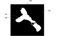
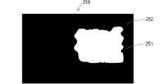
- FIG. 7 is a schematic diagram showing an example of an object surface mask image 250.
- the object surface mask image 250 is composed of a first region 251 (white region in FIG. 7) in which the pixel value indicates "1", and a second region 252 (black region in FIG. 7) in which the pixel value indicates "0".
- the multiple pixels that make up the first region 251 respectively correspond to the multiple object surface points estimated in step s6.
- the first region 251 becomes an object surface region 255 that represents the object surface 15a.
- the position of the object surface region 255 in the object surface mask image 250 represents the position of the object surface 15a in the measurement space 50, and the shape of the object surface region 255 represents the shape of the object surface 15a.
- the estimation unit 20 estimates the object surface 15a of the object 15 based on the depth image 11
- the object surface estimation result by the estimation unit 20 may contain errors due to measurement errors in the distance to each measurement point in the sensor device 10. Therefore, as shown in FIG. 7, the shape of the object surface area 255 included in the object surface mask image 250 generated based on the depth image 11 may differ from the actual shape of the object surface 15a of the object 15 (the shaded area in FIG. 3).
- the correction unit 21 corrects the object surface estimation result by the estimation unit 20 based on the captured image 12. This reduces the error in the object surface estimation result by the estimation unit 20, and the shape of the object surface area 255 included in the object surface mask image 250 becomes closer to the actual shape of the object surface 15a.
- An example of the operation of the correction unit 21 is described below.
- the correction unit 21 performs a segmentation process to divide the color image 12 (in other words, the captured image 12) into a number of small regions such that the boundaries between the small regions are along the edges.
- the correction unit 21 divides the color image 12 into k small regions (k is an integer equal to or greater than 2) using, for example, Simple Linear Iterative Clustering (SLIC).
- SLIC Simple Linear Iterative Clustering
- the small regions are called, for example, clusters or superpixels. Step s11 is described in detail below.
- an edge may be an edge within an object formed by the intersection of multiple faces in the object, or an edge indicating the boundary between the object and the background.
- FIG. 8 is a flowchart showing an example of step s11 in detail.
- an xy Cartesian coordinate system is set as the image coordinate system for images such as the color image 12 and the depth image 11.
- the pixel position of a pixel in an image is represented by a two-dimensional position in the image coordinate system.
- the pixel position of a pixel in an image is represented by an x coordinate and a y coordinate in the image coordinate system.
- the x direction of the image coordinate system is set to the row direction of the image (in other words, the left-right direction)
- the y direction of the image coordinate system is set to the column direction of the image (in other words, the up-down direction).
- step s110 is executed first.
- the modification unit 21 color-converts the R, G, and B components that make up the pixel value of each pixel of the color image 12 into lightness L, chromaticity a, and chromaticity b.
- the color image 12 in which the R, G, and B components of each pixel have been converted into lightness L, chromaticity a, and chromaticity b may be referred to as the color-converted color image 12 or Lab image 12.
- the original color image 12, i.e., the color image 12 before color conversion, may be referred to as the RGB image 12.
- the correction unit 21 initially sets the center of gravity positions of k small regions in the color-converted color image 12 in the image coordinate system.
- the correction unit 21 sets, for example, k center of gravity positions in a matrix at equal intervals. k may be set to, for example, 80 or more, 90 or more, or 100 or more.
- a center of gravity position of interest one center of gravity position of the object of explanation is referred to as a center of gravity position of interest.
- the modification unit 21 adjusts the k initially set center positions based on the color gradient.
- the modification unit 21 sets (3 ⁇ 3) pixels (i.e., nine pixels) consisting of the pixel at the center position of interest and its surrounding eight pixels as adjustment pixels to be used for adjusting the center position of interest.
- the modification unit 21 individually calculates the color gradient (in other words, the Lab gradient) for each of the nine adjustment pixels.
- the modification unit 21 moves the center position of interest to the pixel position of the adjustment pixel with the smallest calculated color gradient among the nine adjustment pixels.
- the modification unit 21 sets the pixel position of the adjustment pixel with the smallest color change from the surrounding pixels among the nine adjustment pixels for the center position of interest as the center position of interest after adjustment. In this way, the modification unit 21 individually adjusts each of the k center positions in the image coordinate system.
- step s113 is executed.
- the modification unit 21 arranges multiple pixels constituting the color-converted color image 12 in a five-dimensional space (also called a five-dimensional coordinate system) whose axes are lightness L, chromaticity a, chromaticity b, x coordinate, and y coordinate.
- the modification unit 21 also sets the positions in the five-dimensional space of the k pixels present at the k adjusted center positions in the image coordinate system as the center positions of gravity of the k small regions in the five-dimensional space.
- the pixel of interest one pixel to be explained will be called the pixel of interest.
- the modification unit 21 provisionally determines, in the five-dimensional space, the small region having the center of gravity position that is closest to the pixel of interest among the k center of gravity positions, as the small region to which the pixel of interest belongs. In the same manner, the modification unit 21 provisionally determines, for each pixel in the five-dimensional space, the small region to which the pixel belongs. In this way, the ranges of the k small regions in the five-dimensional space are provisionally determined.
- step s114 the correction unit 21 recalculates the center of gravity of the k small regions in the five-dimensional space. For example, the correction unit 21 determines the average value of the positions of multiple pixels that belong to the small region in the five-dimensional space as the new center of gravity of the small region.
- the correction unit 21 executes step s113 again, and provisionally re-determines, of the k re-determined center positions, the small region having the center position closest to the pixel of interest as the small region to which the pixel of interest belongs. If the pixels belonging to a small region change, the shape of the small region changes. In the same manner, the correction unit 21 provisionally re-determines, for each pixel in the five-dimensional space, the small region to which the pixel belongs. Then, in step s114, the correction unit 21 re-determines the center positions of the k small regions in the five-dimensional space. Thereafter, the estimation unit 20 repeatedly executes steps s113 and s114.
- the correction unit 21 may terminate the process shown in FIG. 8, for example, when there is at least one small region among the k small regions in which the center of gravity position determined in step s114 has not changed significantly from the center of gravity position determined in the previous step s114.
- the correction unit 21 may also terminate the process shown in FIG. 8, for example, when step s114 has been executed a predetermined number of times.
- the range of the small region at the time when the process shown in FIG. 8 is completed becomes the range of the final small region.
- the small region to which each of the multiple pixels constituting the color-converted color image 12 belongs is finally determined.
- the pixels of the color-converted color image 12 that belong to that small region are finally determined.
- the color-converted color image 12 (in other words, the Lab image 12) is divided into k small regions so that the boundaries between the small regions follow the edges.
- the correction unit 21 divides the original color image 12 into k small regions by superimposing the contours of the k small regions of the color-converted color image 12 onto the original color image 12 (in other words, the RGB image 12).
- FIG. 9 is a schematic diagram showing an example of how the color image 12 shown in FIG. 3 is divided into a plurality of small regions 300.
- the outlines of the small regions 300 are shown with thin lines.
- the color image 12 is divided into a plurality of small regions 300 so that the boundaries between the small regions 300 run along the edges.
- Dividing the color image 12 into a plurality of small regions 300 can also be said to mean that each of the object region 120 and the tray region 125 contained in the color image 12 is divided into a plurality of small regions 300 so that the boundaries between the small regions 300 run along the edges.
- the correction unit 21 executes step s12 after executing the segmentation process in step s11.
- the correction unit 21 executes a second mask process using the object mask image 200 generated in step s1 to extract an object region 120 (also called a divided object region 120) divided into multiple small regions from the color image 12 (also called a divided color image 12) divided into multiple small regions as shown in FIG. 9.
- an object region 120 also called a divided object region 120
- the color image 12 also called a divided color image 12
- the correction unit 21 identifies multiple pixels in the divided color image 12 that are located at the same pixel positions as the multiple pixels that make up the object region 201 in the object mask image 200. In other words, the correction unit 21 identifies multiple pixels in the divided color image 12 that are located at the same pixel positions as the multiple pixels in the object mask image 200 that have a pixel value of "1". Then, the correction unit 21 extracts an area consisting of the identified multiple pixels from the divided color image 12 as the divided object region 120.
- the correction unit 21 divides the area of the object 15 included in the photographed image 12 (i.e., the object area 120) into a plurality of small areas with boundaries along the edges of the object 15 based on the color information shown in the photographed image 12. It can also be said that the correction unit 21 divides the object area 120 into a plurality of small areas based on the first color information within the surface of the object surface 15a shown in the photographed image 12 and the second color information around the object surface 15a. It can also be said that the correction unit 21 divides the object area 120 into a plurality of small areas based on the color tone difference or color distribution of the object 15 shown in the photographed image 12. It can also be said that the correction unit 21 divides the object area 120 into a plurality of small areas based on the color tone difference or color distribution within the surface of the object surface 15a shown in the photographed image 12.
- step s13 is executed.
- the correction unit 21 shapes the object surface region 255 of the object surface mask image 250 based on the multiple small regions that make up the object region 120 to be divided. That is, the shape of the object surface region 255 is adjusted. For example, for each of the multiple small regions that make up the object region 120 to be divided, the correction unit 21 calculates the occupancy rate of the object surface region 255 within the contour when the contour of the small region is superimposed on the object surface mask image 250. Then, the correction unit 21 shapes the object surface region 255 based on the occupancy rates calculated for the multiple small regions.
- a small region when mentioned in the explanation of step s13, it means a small region that makes up the object region 120 to be divided. Also, hereinafter, one small region to be explained among the multiple small regions that make up the object region 120 to be divided is called a small region of interest.
- the correction unit 21 determines the occupancy rate for a small region of interest, it first superimposes the contour of the small region of interest on the target surface mask image 250.
- the correction unit 21 superimposes the contour of the small region of interest on the target surface mask image 250 so that the position of the contour of the small region of interest in the target surface mask image 250 is the same as the position of the contour of the small region of interest in the color image 12.
- the correction unit 21 superimposes the contour of the small region of interest on the target surface mask image 250 so that the pixel positions of multiple pixels within the contour of the small region of interest in the target surface mask image 250 match the pixel positions of multiple pixels within the contour of the small region of interest in the color image 12, respectively.
- the modification unit 21 obtains, for example, the total number of pixels, which is the number of all pixels present in the small region of interest superimposed on the target surface mask image 250.
- the modification unit 21 also obtains, for example, the number of pixels of the target surface area 255 present in the small region of interest superimposed on the target surface mask image 250, which is the number of occupied pixels.
- the modification unit 21 determines, for example, the value obtained by dividing the number of occupied pixels by the total number of pixels as the occupancy rate of the target surface area 255 within the contour of the small region of interest. In this way, the modification unit 21 obtains the occupancy rate for each small region.
- the correction unit 21 determines whether or not the area within the outline of each small region in the target surface mask image 250 corresponds to the target surface 15a, for example, based on the occupancy rate of the small region. For example, the correction unit 21 regards the area within the outline of a small region having an occupancy rate greater than a threshold value in the target surface mask image 250 (also called the contour superimposed target surface mask image 250) in which the outlines of multiple small regions are superimposed, as an area corresponding to the target surface 15a. On the other hand, the correction unit 21 regards the area within the outline of a small region having an occupancy rate less than a threshold value in the contour superimposed target surface mask image 250, as an area not corresponding to the target surface 15a.
- a threshold value in the target surface mask image 250 also called the contour superimposed target surface mask image 250
- the correction unit 21 regards the area within the outline of a small region having an occupancy rate less than a threshold value in the contour superimposed target surface mask image 250, as an area not corresponding to the target surface 15a.
- the correction unit 21 may regard the area within the outline of a small region having an occupancy rate equal to the threshold value in the contour superimposed target surface mask image 250 as an area corresponding to the target surface 15a, or may regard it as an area not corresponding to the target surface 15a.
- a small area whose occupancy rate is greater than the threshold value will be referred to as a small area with a large occupancy rate
- a small area whose occupancy rate is less than the threshold value will be referred to as a small area with a small occupancy rate.
- the correction unit 21 regards all of the area within the contour of the small region in the contour superimposed target surface mask image 250 as an area corresponding to the target surface 15a.
- the correction unit 21 regards all of the area within the contour of the small region in the contour superimposed target surface mask image 250 as an area not corresponding to the target surface 15a.
- the threshold value may be, for example, 0.7 or more, 0.8 or more, 0.9 or more, or some other value.
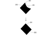
- Figures 10 and 11 are schematic diagrams for explaining an example of the operation of the correction unit 21.
- the upper part of Figure 10 shows an example of an area 260 within the contour of a small area with a large occupancy rate (also called an area within the contour with a large occupancy rate) in the contour superimposition target surface mask image 250.
- the upper part of Figure 11 shows an example of an area 261 within the contour of a small area with a small occupancy rate (also called an area within the contour with a small occupancy rate) in the contour superimposition target surface mask image 250.
- the correction unit 21 regards all of the large occupancy intra-contour area 260 in the contour superimposed target surface mask image 250 as an area corresponding to the target surface 15a, and resets the pixel values of all pixels constituting the large occupancy intra-contour area 260 to "1."
- the lower part of Figure 10 shows an example of a large occupancy intra-contour area 260 in which the pixel values of all pixels have been reset to "1.”
- the large occupancy intra-contour area 260 in which the pixel values of all pixels have been reset to "1" constitutes part of the shaped target surface area 255.
- the correction unit 21 regards all of the small occupancy rate intra-contour area 261 in the contour superimposition target surface mask image 250 as areas that do not correspond to the target surface 15a, and resets the pixel values of all pixels that make up the small occupancy rate intra-contour area 261 to "0.”
- the lower part of Figure 11 shows an example of a small occupancy rate intra-contour area 261 in which the pixel values of all pixels have been reset to "0.”
- the correction unit 21 resets the pixel values of all pixels in each of the contour-overlapped target surface mask image 250, which has a large occupancy rate, to "1" and resets the pixel values of all pixels in each of the contour-overlapped target surface mask image 261, which has a small occupancy rate, to "0," so that the target surface area 255 (i.e., the area with pixel values of "1") included in the contour-overlapped target surface mask image 250 is shaped in accordance with the actual shape of the target surface 15a. As a result, the shape of the target surface area 255 after shaping becomes closer to the actual shape of the target surface 15a.
- a target surface mask image 250 in which the target surface area 255 has been shaped is obtained.
- the target surface mask image 250 in which the target surface area 255 has been shaped is referred to as the shaped target surface mask image 250a.
- SLIC is used to divide the color image 12 into multiple small regions such that the boundaries between the small regions are along the edges
- a segmentation algorithm other than SLIC may be used to divide the color image 12 into multiple small regions.
- Watershed or Quickshift may be used to segment the color image 12.
- the color image 12 is divided into a plurality of small regions after color conversion, but the color image 12 may be divided into a plurality of small regions without color conversion.
- step s110 is not executed, and in step s111, the center positions of k small regions are initially set for the color image 12, which is an RGB image.
- step s112 is executed in a similar manner.
- the correction unit 21 arranges a plurality of pixels constituting the color image 12 (i.e., the RGB image 12) in a five-dimensional space with the R component, the G component, the B component, the x coordinate, and the y coordinate as axes.
- step s114 is executed in a similar manner. Thereafter, steps s113 and s114 are repeatedly executed, and the color image 12, which is an RGB image, is divided into k small regions so that the boundaries between the small regions are along the edges.
- the color image 12 is divided into a plurality of small regions, and then the object region is extracted from the color image 12.
- the object region may be divided into a plurality of small regions after it is extracted from the color image 12.
- the processing device 1 may also estimate each of the multiple object surfaces included in the surface of the object 15.
- the object surface described so far that is, the plane with the largest area as seen from the sensor device 10 in the object measurement surface, is defined as the first object surface.
- the estimation unit 20 removes the multiple object surface points representing the first object surface estimated in step s6 from the object point cloud generated in step s3 to correct the object point cloud.
- the estimation unit 20 executes steps s4 to s6 using the corrected object point cloud to estimate the multiple object surface points representing the second object surface.
- the second object surface is the plane with the second largest area as seen from the sensor device 10 in the object measurement surface.
- step s7 the estimation unit 20 generates a second object surface mask image 250 representing the second object surface.
- step s13 the correction unit 21 similarly shapes the second object surface region representing the second object surface included in the second object surface mask image 250 based on the multiple small regions.
- the processing device 1 estimates a third object surface different from the first object surface and the second object surface
- a plurality of object surface points representing the estimated second object surface are removed from the corrected object point cloud, and the object point cloud is further corrected.
- the estimation unit 20 executes steps s4 to s6 using the further corrected object point cloud to estimate a plurality of object surface points representing the third object surface.
- the third object surface is the plane having the third largest area as seen from the sensor device 10 on the object measurement surface.
- step s7 the estimation unit 20 generates a third object surface mask image 250 representing the third object surface.
- step s13 the correction unit 21 shapes the third object surface region representing the third object surface, which is included in the third object surface mask image 250, based on a plurality of small regions. Thereafter, in a similar manner, the processing device 1 can estimate yet another object surface.
- the target surface estimation result corrected by the processing device 1 can be used in various situations. For example, when the suction unit suctions the target surface 15a, the suction position on the target surface 15a where the suction unit suctions may be determined based on the target surface estimation result corrected by the correction unit 21.
- FIG. 13 is a schematic diagram showing an example of a robot system 900 including a robot 500 having an adsorption portion that adsorbs the target surface 15a of an object 15.
- the robot system 900 includes, for example, the robot 500, a robot control device 800 that controls the robot 500, and a processing device 1.
- the robot 500 is, for example, an arm-type robot, and includes an arm 510 and an end effector 520 connected to the arm 510.
- the end effector 520 includes a suction pad 521 that functions as an adsorption section.
- the suction pad 521 is capable of adsorbing the target surface 15a of the object 15 and holding the object 15.
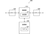
- FIG. 14 is a schematic diagram showing an example of the configuration of a robot control device 800.
- the robot control device 800 includes, for example, a control unit 810, a storage unit 820, an interface 830, and an interface 840.
- the robot control device 800 can also be considered, for example, a robot control circuit.
- the robot control device 800 can also be considered, for example, a computer device.
- the interface 830 is capable of communicating with the interface 5 of the processing device 1.
- the interface 840 is capable of communicating with the robot 500.
- the interface 840 may communicate with the robot 500 via wired or wireless communication.
- the control unit 810 is capable of managing the overall operation of the robot control device 800 by controlling the other components of the robot control device 800.
- the control unit 810 has, for example, a configuration similar to that of the control unit 2 provided in the processing device 1, and the control unit 810 may have, for example, a CPU as a processor.
- the memory unit 820 has, for example, the same configuration as the memory unit 3 of the processing device 1.
- the memory unit 820 stores, for example, a program 821 for controlling the robot control device 800.
- the various functions of the control unit 810 are realized, for example, by the CPU of the control unit 810 executing the program 821 in the memory unit 820.
- the control unit 810 can control the robot 500 through the interface 840.
- the control unit 810 can control, for example, the arm 510 and the end effector 520.
- the robot control device 800 may be composed of a robot control device that controls the arm 510 and a robot control device that controls the end effector 520.
- the adsorption position on the target surface 15a may be determined by the processing device 1, or by a device other than the processing device 1.
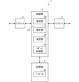
- Figure 15 is a schematic diagram showing an example of the configuration of a processing device 1 that determines the adsorption position.
- the control unit 2 includes a determination unit 22 as a functional block.
- the determination unit 22 is realized by the CPU of the control unit 2 executing the program 30 in the storage unit 3.
- the determination unit 22 determines the suction position on the target surface 15a where the suction pad 521 is to be suctioned, based on the target surface estimation result corrected by the correction unit 21. Note that all or some of the functions of the determination unit 22 may be realized by a hardware circuit that does not require software to realize the function.
- FIG. 16 is a schematic diagram showing an example of a distance transformation image 270.
- the actual distance transformation image 270 is a grayscale image, but in FIG. 16, for convenience of illustration, the distance transformation image 270 is shown with a white portion 271 and a black portion 272.
- the white portion 271 is an area in the distance transformed image 270 where the pixel values are relatively large.
- the black portion 272 is an area in the distance transformed image 270 where the pixel values are relatively small.
- the white portion 271 corresponds to an area in the target surface region 255 of the shaped target surface mask image 250a where the shortest straight-line distance from the edge is relatively large.
- the white portion 271 represents the central region in the target surface region 255 that is far from the edge (in other words, the contour). It can also be said that the white portion 271 represents the central region in the target surface that is far from the edge.
- the determination unit 22 determines the position of the center of gravity of the target surface area 255 of the shaped target surface mask image 250a. For example, the determination unit 22 determines the average value of the x coordinates of a plurality of pixels constituting the target surface area 255 and the average value of the y coordinates of the plurality of pixels. The determination unit 22 then determines the average value of the determined x coordinates as the x coordinate of the center of gravity, and the average value of the determined y coordinates as the y coordinate of the center of gravity.
- the determination unit 22 sets the center of gravity in the distance transformed image 270 at the same position as the center of gravity of the target surface area 255.
- the determination unit 22 then identifies, among the multiple pixels constituting the distance transformed image 270, a pixel whose pixel value is equal to or greater than a threshold value and which is closest to the center of gravity, and sets the pixel position of the identified pixel as the adsorption pixel position.
- the adsorption pixel position represents a position on the target surface that is far from the edge and close to the center of gravity.
- the determination unit 22 then sets an adsorption point 280 at the adsorption pixel position in the color image 12 in which the target surface appears.
- FIG. 17 is a schematic diagram showing an example of a color image 12 in which an adsorption point 280 is set.
- the adsorption point 280 is located at a position far from the edge and close to the center of gravity on the object surface shown in the color image 12.
- the determination unit 22 determines the position at which the adsorption point 280 is set on the object surface 15a shown in the color image 12 as the adsorption position by the suction pad 521.
- the processing device 1 notifies the robot control device 800 of the suction position determined by the determination unit 22 through the interface 5.
- the control unit 810 controls the position of the suction pad 521 based on the suction position notified to the interface 830.
- the control unit 810 causes the suction pad 521 to be adsorbed to the target surface 15a so that the suction position notified to the interface 830 coincides with the center of the suction pad 521.
- FIG. 17 shows the outer shape 285 of the suction pad 521 when the suction pad 521 adsorbs the target surface 15a so that the center of the suction pad 521 coincides with the adsorption position determined by the determination unit 22.
- the entire suction pad 521 is in contact with the target surface 15a, and the suction pad 521 can properly adsorb the target surface 15a.
- FIG. 18 is a schematic diagram showing an example of a color image 12 in which an adsorption point 280 is set that is determined by the determination unit 22 in a similar manner based on the unshaped target surface mask image 250 shown in FIG. 7.
- the adsorption point 280 is set near the edge of the target surface 15a shown in the color image 12. Therefore, a part of the adsorption pad 521 that adsorbs the target surface 15a extends beyond the target surface 15a, making it difficult for the adsorption pad 521 to adsorb the target surface 15a.
- the suction position where the suction part suctions the target surface 15a is set based on the target surface estimation result corrected by the correction unit 21, so that the suction part can appropriately suction the target surface 15a.
- the control unit 810 of the robot control device 800 may include a determination unit 811 similar to the determination unit 22 of the processing device 1.
- the processing device 1 notifies the robot control device 800 of the target surface estimation result corrected by the correction unit 21.
- the determination unit 811 determines the suction position on the target surface 15a where the suction pad 521 is to be suctioned based on the corrected target surface estimation result (in other words, the detection result of the target surface 15a by the detection unit 25) in the same manner as the determination unit 22.
- the control unit 810 controls the position of the suction pad 521 based on the suction position determined by the determination unit 811.
- the control unit 810 includes the determination unit 811, it can be said that the control unit 810 controls the robot 500 based on the detection result of the target surface 15a by the detection unit 25.
- the processing device 1 may also control the robot 500 based on the detection result of the target surface 15a by the detection unit 25.
- FIG. 20 is a schematic diagram showing an example of the configuration of the processing device 1 in this case.
- the control unit 2 includes a robot control unit 23 that controls the robot 500.
- the robot control unit 23 can control the robot 500, for example, through the interface 5.
- the robot control unit 23, like the control unit 810, controls the position of the suction pad 521 based on the suction position determined by the determination unit 22.
- the processing device 1 shown in FIG. 20 can be said to be a robot control device 1 that controls the robot 500.
- control unit 2 or control unit 810 may determine a placement position on the placement surface on which the robot places the object, based on the corrected target surface estimation result.
- Example of setting the threshold for specific surface estimation and the threshold for target surface point estimation> For example, consider a case where the specific surface estimation threshold value used in step s5 is the same as the target surface point estimation threshold value used in step s6. In this case, when the specific surface estimation threshold value and the target surface point estimation threshold value are large, it may not be possible to properly estimate a specific surface that is on the same plane as the target surface. On the other hand, when the specific surface estimation threshold value and the target surface point estimation threshold value are small, it may be possible to properly estimate a specific surface, but it may not be possible to properly estimate a plurality of target surface points that represent the target surface included in the target object point cloud. This point will be described below.
- the color image 12 shown in FIG. 21 shows an object 15 with a step on its upper surface.
- the higher surface 150 of the upper surface is the object surface 15a, and the lower surface 151 of the upper surface is not the object surface 15a.
- Figures 22 and 23 are schematic diagrams showing an example of a target surface mask image 250 generated by the estimation unit 20 based on the color image 12A and its corresponding depth image.
- Figure 22 shows a target surface mask image 250 when the specific surface estimation threshold value and the target surface point estimation threshold value are set to relatively large values (e.g., 1.0 mm).
- Figure 23 shows a target surface mask image 250 when the specific surface estimation threshold value and the target surface point estimation threshold value are set to relatively small values (e.g., 0.5 mm).
- the target surface mask image 250 shown in FIG. 22 shows not only the higher surface 150 as the target surface 15a, but also the lower surface 151 that is not the target surface 15a. This is because the specific surface was not properly estimated.
- the target surface mask image 250 shown in FIG. 23 does not show the lower surface 151 that is not the target surface 15a.
- the shape of the higher surface 150 as the target surface 15a shown in the target surface mask image 250 is significantly different from the actual shape. This is because the multiple object points representing the higher surface 150 as the target surface 15a were not properly estimated.
- FIG. 24 also shows an example of candidate surfaces 320a and 320b that are set in the camera coordinate system in step s4.
- Candidate surface 320a passes diagonally through the higher surface of the top surface of point cloud existence range 310 and the lower surface of the top surface of point cloud existence range 310.
- Candidate surface 320b includes the higher surface of the top surface of point cloud existence range 310.
- 24 also shows, in a bold line, an example of a range 315aa where, among the multiple object points (in other words, measurement points) on the higher surface 150 of the upper surface of the object 15, there are object points whose distance from the candidate surface 320a is equal to or less than the specific surface estimation threshold value (i.e., 1.0 mm). 24 also shows, in a bold line, an example of a range 315ab where, among the multiple object points on the lower surface 151 of the upper surface of the object 15, there are object points whose distance from the candidate surface 320a is equal to or less than the specific surface estimation threshold value.
- the specific surface estimation threshold value i.e., 1.0 mm
- candidate surface 320b it is desirable for candidate surface 320b to be estimated as a specific surface that is in the same plane as the target surface.
- the specific surface estimation threshold i.e., 1.0 mm
- candidate surface 320a, not candidate surface 320b is estimated as a specific surface that is in the same plane as the target surface.
- the higher surface 150 which is the target surface 15a
- the lower surface 151 which is not the target surface 15a
- FIG. 25 is a schematic diagram for explaining an example of the specific surface estimation process when the specific surface estimation threshold and the target surface point estimation threshold are 0.5 mm.
- the contents shown in FIG. 25 are the same as those shown in FIG. 24.
- the number of object points whose distance from the candidate surface 320b is equal to or less than the specific surface estimation threshold i.e., 0.5 mm
- the candidate surface 320b is estimated as the specific surface that is in the same plane as the target surface.
- the lower surface 151 that is not the target surface 15a does not appear in the target surface mask image 250, but the higher surface 150 appears as the target surface 15a.
- the object points representing the target surface 15a included in the object point cloud include a relatively large number of object points whose distance from the candidate surface 320b is greater than 0.5 mm due to distance measurement errors in the sensor device 10, the object points representing the target surface 15a will not be estimated properly, and the shape of the higher surface 150 as the target surface 15a shown in the target surface mask image 250 will be significantly different from the actual shape, as shown in Figure 23.
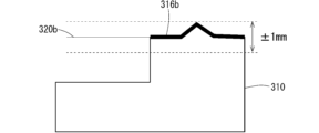
- FIG. 26 is a schematic diagram showing an example of a state in which a relatively large number of object points that represent the object surface 15a are included at a distance from the candidate surface 320b that is greater than 0.5 mm.
- an example of a range 316b in which object points that are 0.5 mm or less away from the candidate surface 320b exist among the object points on the upper surface 150 of the object 15 (in other words, the object points that represent the object surface 15a) on the higher surface 150 of the object 15 are included.
- FIG. 26 is a schematic diagram showing an example of a state in which a relatively large number of object points that represent the object surface 15a are included at a distance from the candidate surface 320b that is greater than 0.5 mm.
- an example of a range 316b in which object points that are 0.5 mm or less away from the candidate surface 320b exist among the object points on the upper surface 150 of the object 15 (in other words, the object points that represent the object surface 15a) on the higher surface 150 of the object 15 are
- 26 shows a range 316bb in which object points that are greater than 0.5 mm away from the candidate surface 320b exist among the object points on the upper surface 150 of the object 15 (in other words, the object points that represent the object surface 15a) on the higher surface 150 of the object 15 are included, with a line thinner than the range 316b.
- FIG. 27 is a schematic diagram showing an example of a target surface mask image 250 when the threshold for estimating a specific surface is 0.5 mm and the threshold for estimating a target surface point is 1.0 mm.
- the target surface mask image 250 shown in FIG. 27 does not show the lower surface 151 that is not the target surface 15a, and furthermore, the shape of the higher surface 150 as the target surface 15a shown in the target surface mask image 250 is close to the actual shape. This is because the specific surface is correctly estimated, and as shown in FIG. 28, the multiple object points representing the target surface 15a include almost no object points whose distance from the candidate surface 320b is greater than 1.0 mm.
- the accuracy of estimating the target surface is improved by separately setting the threshold for estimating specific surfaces and the threshold for estimating target surface points.
- the robustness of the target surface estimation process against distance measurement errors in the sensor device 10 is improved.
- the robustness of the target surface estimation process against errors (in other words, noise) contained in the depth image 11 is improved.
- the threshold value for estimating object surface points is too large, object points (in other words, measurement points) that are not on the same plane as the object surface may be estimated as object surface points.
- the threshold value for estimating object surface points is too small, the robustness of the object surface estimation process against errors contained in the depth image 11 decreases.
- the threshold value for estimating the object surface point is set, for example, based on the maximum error of the distance represented by the depth image 11. This makes it possible to reduce the possibility that an object point that is not on the same plane as the object surface is estimated as an object surface point, while maintaining the robustness of the object surface estimation process against errors contained in the depth image 11. In other words, it is possible to improve the accuracy of estimating the object surface.
- the threshold value for estimating the target surface point for example, the depth image 11 generated by the sensor device 10 in the real environment where the sensor device 10 is actually used is used. This depth image 11 is called the depth image 11 in the real environment. Then, the maximum error of the distance represented by the depth image 11 in the real environment is obtained by experiment or simulation. For example, the error from the actual distance for each of the multiple measured distances represented by the pixel values of the multiple pixels that make up the depth image 11 in the real environment is obtained by experiment or simulation. Then, the maximum error among the errors obtained for the multiple measured distances is set to the maximum error of the distance represented by the depth image 11 in the real environment.
- the threshold value for estimating the target surface point may be set to the same value as the maximum error of the distance represented by the depth image 11 in the real environment, or may be set to a value obtained by multiplying the maximum error by a predetermined adjustment coefficient.
- the specific surface estimation threshold the higher the accuracy of the specific surface estimation.
- RANSAC for example
- the object point cloud generated from the depth image 11 needs to contain three or more object points whose distance from the object surface is equal to or less than the specific surface estimation threshold. If the specific surface estimation threshold is too small, the number of object points whose distance from the object surface is equal to or less than the specific surface estimation threshold may be less than three, and the specific surface may not be properly estimated.
- the threshold for estimating the specific surface is therefore set, for example, based on the error distribution of the distance represented by the depth image 11. This makes it possible to improve the accuracy of estimating the specific surface.
- the distribution of errors at multiple measurement distances represented by the pixel values of multiple pixels constituting depth image 11 in the real environment is obtained as the error distribution of the distance represented by depth image 11 (also called distance error distribution).
- the relationship between each error value and the number of pixels corresponding to the measurement distance having that value of error is obtained.
- the number of pixels corresponding to the measurement distance having that value of error is obtained for depth image 11 in the real environment.
- the probability that the error in the measured distance corresponding to one pixel included in the depth image 11 is equal to or less than the threshold for estimating a specific surface is calculated.
- the threshold for estimating a specific surface is represented as x.
- the probability that the error in the measured distance corresponding to one pixel included in the depth image 11 is equal to or less than x is represented as r(x).
- the probability r(x) is expressed by the following formula (1).
- S means the number of pixels constituting the depth image 11 (i.e., the total number of pixels in the depth image 11).
- m means the number of pixels corresponding to the measured distance that has an error of x or less in the obtained distance error distribution.
- a probability P1(x) is calculated that the number of pixels corresponding to the measurement distance with an error of x or less is 2 or less among the pixels included in the depth image 11 and corresponding to the target surface 15a.
- the pixels included in the depth image 11 corresponding to the target surface 15a can also be said to be pixels corresponding to the measurement points included in the depth image 11 on the target surface 15a (in other words, the measurement points representing the target surface 15a).
- the probability P1(x) is the sum of the probability that the number of pixels corresponding to the measurement distance with an error of x or less is 0 among the pixels included in the depth image 11 and corresponding to the target surface 15a, the probability that the number of pixels corresponding to the measurement distance with an error of x or less is 1, and the probability that the number of pixels corresponding to the measurement distance with an error of x or less is 2.
- the probability P1(x) is expressed by the following formula (2) using the combination C.
- N means the number of pixels contained in the depth image 11 that correspond to the target surface 15a.
- the probability P1(x) is used to find the probability P2(x) that the number of pixels corresponding to the measurement distance with an error of x or less will be 3 or more among the multiple pixels corresponding to the target surface 15a contained in the depth image 11.
- the probability P2(x) is expressed by the following formula (3). The larger the specific surface estimation threshold value x, the larger the probability P2(x).
- the threshold value x for estimating a specific surface is set to a value that is as small as possible while still ensuring that the probability P2(x) is sufficiently large. For example, if a value of 0.999 or greater for the probability P2(x) is sufficient, then the threshold value x for estimating a specific surface is set to a value that ensures that the probability P2(x) is 0.999.
- the threshold value for specific surface estimation and the threshold value for target surface point estimation are set with different setting criteria, so that, for example, the threshold value for target surface point estimation is set to be greater than the threshold value x for specific surface estimation.
- the threshold value for specific surface estimation and the threshold value for target surface point estimation are set using different setting criteria, depending on the distance measurement error in the sensor device 10, the threshold value for specific surface estimation and the threshold value for target surface point estimation may be set to the same value, or the threshold value for specific surface estimation may be set to a value greater than the threshold value for target surface point estimation.
- an arm-type robot is described as an application example of the processing device 1, but the processing device 1 may also be applied to a self-propelled robot such as an AGV (Automatic Guided Vehicle) or an AMR (Autonomous Mobile Robot), or may be applied to a humanoid robot.
- the processing device 1 may also be applied to a nursing robot or a remote-controlled robot, etc.
- the object 15 was an industrial product, but this is not limited to this.
- the object 15 may be, for example, food such as vegetables or bread, furniture such as a chest of drawers, or household goods such as a toothbrush or a cup.
- This disclosure includes the following:
- the processing device includes a detection unit that detects partial surfaces included in the surface based on surface information about the surface of the object acquired based on distance information to the object and color information indicated by a color image or grayscale image showing the object and its surroundings.
- the detection unit has an estimation unit that acquires the surface information based on the distance information and estimates the partial surface based on the acquired surface information, and a correction unit that corrects the estimation result of the estimation unit based on the color information and sets the corrected estimation result as the detection result of the partial surface.
- the correction unit divides the region of the object contained in the color image or the grayscale image into a plurality of small regions based on the color information so that the boundaries follow the edges of the object, and corrects the estimation result based on the plurality of small regions.
- the correction unit determines whether or not the area within the contour of the small region in the mask image corresponds to the partial surface based on the occupancy rate of the small region.
- a processing device according to any one of (1) to (8), wherein the estimation unit generates a point cloud representing the surface of the object as the surface information based on a depth image indicating the distance information, sets a plurality of candidate surfaces based on the point cloud, estimates a candidate surface on the same plane as the object surface from the plurality of candidate surfaces based on a comparison result between a distance from the candidate surface to a point included in the point cloud and a first threshold value, and estimates a plurality of points representing the partial surface included in the point cloud based on a comparison result between a distance from the candidate surface estimated to be on the same plane as the object surface to a point included in the point cloud and a second threshold value.
- the first threshold value is based on an error distribution of the distance represented by the depth image.
- the second threshold is based on a maximum error in the distance represented by the depth image.
- processing devices (1) to (13) above further comprising a determination unit that determines an adsorption position on the partial surface where the adsorption unit is to adsorb based on the detection result of the partial surface by the detection unit.
- the processing device of (14) above includes a control unit that controls the position of the suction unit based on the suction position determined by the determination unit.
- the robot control device includes a control unit that controls the robot based on the detection result of the partial surface by the detection unit provided in any one of the processing devices (1) to (13) above.
- the robot system includes the robot control device described above in (16) and a robot controlled by the control unit provided in the robot control device.
- the program is a program for causing a computer device to function as any one of the processing devices (1) to (15) above.
- the program is a program for causing a computer device to function as the robot control device described above in (16).
- Processing device 11 Depth image 12 (12A) Photographed image, color image, grayscale image 15 Object 15a Object surface (partial surface) 20 Estimation unit 21 Correction unit 22, 811 Determination unit 25 Detection unit 30, 821 Program 50 Measurement space 120 Object region 250 Object surface mask image 251 Object surface region 300 Small region 320a, 320b Candidate surface 521 Adsorption unit 800 Robot control device 810 Control unit 900 Robot system
Landscapes
- Engineering & Computer Science (AREA)
- Human Computer Interaction (AREA)
- Robotics (AREA)
- Mechanical Engineering (AREA)
- Computer Vision & Pattern Recognition (AREA)
- Physics & Mathematics (AREA)
- General Physics & Mathematics (AREA)
- Theoretical Computer Science (AREA)
- Image Analysis (AREA)
Priority Applications (2)
| Application Number | Priority Date | Filing Date | Title |
|---|---|---|---|
| JP2025530165A JPWO2025005127A1 (https=) | 2023-06-30 | 2024-06-26 | |
| EP24831986.5A EP4738249A1 (en) | 2023-06-30 | 2024-06-26 | Processing device, robot control device, robot system, and program |
Applications Claiming Priority (2)
| Application Number | Priority Date | Filing Date | Title |
|---|---|---|---|
| JP2023-108254 | 2023-06-30 | ||
| JP2023108254 | 2023-06-30 |
Publications (1)
| Publication Number | Publication Date |
|---|---|
| WO2025005127A1 true WO2025005127A1 (ja) | 2025-01-02 |
Family
ID=93938628
Family Applications (1)
| Application Number | Title | Priority Date | Filing Date |
|---|---|---|---|
| PCT/JP2024/023154 Ceased WO2025005127A1 (ja) | 2023-06-30 | 2024-06-26 | 処理装置、ロボット制御装置、ロボットシステム及びプログラム |
Country Status (3)
| Country | Link |
|---|---|
| EP (1) | EP4738249A1 (https=) |
| JP (1) | JPWO2025005127A1 (https=) |
| WO (1) | WO2025005127A1 (https=) |
Citations (5)
| Publication number | Priority date | Publication date | Assignee | Title |
|---|---|---|---|---|
| WO2005088244A1 (ja) * | 2004-03-17 | 2005-09-22 | Sony Corporation | 平面検出装置、平面検出方法、及び平面検出装置を搭載したロボット装置 |
| JP2007041656A (ja) * | 2005-07-29 | 2007-02-15 | Sony Corp | 移動体制御方法および移動体 |
| JP2014085940A (ja) | 2012-10-25 | 2014-05-12 | Sharp Corp | 平面検出装置およびそれを備えた自律移動装置 |
| JP2017087317A (ja) * | 2015-11-04 | 2017-05-25 | トヨタ自動車株式会社 | 操作対象物の状態推定装置 |
| WO2021177239A1 (ja) * | 2020-03-05 | 2021-09-10 | ファナック株式会社 | 取り出しシステム及び方法 |
-
2024
- 2024-06-26 JP JP2025530165A patent/JPWO2025005127A1/ja active Pending
- 2024-06-26 WO PCT/JP2024/023154 patent/WO2025005127A1/ja not_active Ceased
- 2024-06-26 EP EP24831986.5A patent/EP4738249A1/en active Pending
Patent Citations (5)
| Publication number | Priority date | Publication date | Assignee | Title |
|---|---|---|---|---|
| WO2005088244A1 (ja) * | 2004-03-17 | 2005-09-22 | Sony Corporation | 平面検出装置、平面検出方法、及び平面検出装置を搭載したロボット装置 |
| JP2007041656A (ja) * | 2005-07-29 | 2007-02-15 | Sony Corp | 移動体制御方法および移動体 |
| JP2014085940A (ja) | 2012-10-25 | 2014-05-12 | Sharp Corp | 平面検出装置およびそれを備えた自律移動装置 |
| JP2017087317A (ja) * | 2015-11-04 | 2017-05-25 | トヨタ自動車株式会社 | 操作対象物の状態推定装置 |
| WO2021177239A1 (ja) * | 2020-03-05 | 2021-09-10 | ファナック株式会社 | 取り出しシステム及び方法 |
Also Published As
| Publication number | Publication date |
|---|---|
| EP4738249A1 (en) | 2026-05-06 |
| JPWO2025005127A1 (https=) | 2025-01-02 |
Similar Documents
| Publication | Publication Date | Title |
|---|---|---|
| CN112991193B (zh) | 深度图像修复方法、设备及计算机可读存储介质 | |
| JP6415066B2 (ja) | 情報処理装置、情報処理方法、位置姿勢推定装置、ロボットシステム | |
| JP6573354B2 (ja) | 画像処理装置、画像処理方法、及びプログラム | |
| TWI520078B (zh) | Optical flow tracking method and device | |
| CN113052907B (zh) | 一种动态环境移动机器人的定位方法 | |
| CN110555878B (zh) | 物体空间位置形态的确定方法、装置、存储介质及机器人 | |
| WO2017093037A1 (en) | Method for identification of candidate points as possible characteristic points of a calibration pattern within an image of the calibration pattern | |
| WO2015006224A1 (en) | Real-time 3d computer vision processing engine for object recognition, reconstruction, and analysis | |
| CN109472820B (zh) | 单目rgb-d相机实时人脸重建方法及装置 | |
| CN105488791B (zh) | 自然背景中图像边缘的定位方法及装置 | |
| CN107680140B (zh) | 一种基于Kinect相机的深度图像高分辨率重构方法 | |
| JP6817742B2 (ja) | 情報処理装置およびその制御方法 | |
| JP7178803B2 (ja) | 情報処理装置、情報処理装置の制御方法およびプログラム | |
| JP7121936B2 (ja) | カメラ校正情報取得装置、画像処理装置、カメラ校正情報取得方法およびプログラム | |
| CN108550167B (zh) | 深度图像生成方法、装置及电子设备 | |
| CN114494312A (zh) | 训练从对象图像中识别对象的对象拓扑的机器学习模型的设备和方法 | |
| CN108564622A (zh) | 实现定位板图像中亚像素级角点定位的方法 | |
| CN112634377B (zh) | 扫地机器人的相机标定方法、终端和计算机可读存储介质 | |
| CN113723432A (zh) | 一种基于深度学习的智能识别、定位追踪的方法及系统 | |
| CN117808880A (zh) | 一种单目视觉的空间合作目标位姿测量方法 | |
| JP2022508434A (ja) | 回転仮説を決定することによって画像を処理する方法及びシステム | |
| US20250348982A1 (en) | Display video correction device, display video correction method, and recording medium | |
| CN117095055A (zh) | 一种基于混合标签的鲁棒性标志块及其定位方法 | |
| WO2025005127A1 (ja) | 処理装置、ロボット制御装置、ロボットシステム及びプログラム | |
| CN115953465A (zh) | 基于模块化机器人实训平台的三维视觉随机抓取处理方法 |
Legal Events
| Date | Code | Title | Description |
|---|---|---|---|
| 121 | Ep: the epo has been informed by wipo that ep was designated in this application |
Ref document number: 24831986 Country of ref document: EP Kind code of ref document: A1 |
|
| ENP | Entry into the national phase |
Ref document number: 2025530165 Country of ref document: JP Kind code of ref document: A |
|
| WWE | Wipo information: entry into national phase |
Ref document number: 2025530165 Country of ref document: JP |
|
| WWE | Wipo information: entry into national phase |
Ref document number: 2024831986 Country of ref document: EP |
|
| NENP | Non-entry into the national phase |
Ref country code: DE |
|
| ENP | Entry into the national phase |
Ref document number: 2024831986 Country of ref document: EP Effective date: 20260130 |
|
| ENP | Entry into the national phase |
Ref document number: 2024831986 Country of ref document: EP Effective date: 20260130 |