WO2025004845A1 - 液体充填済み培養バッグ、液体充填済み培養バッグの製造方法、及び液体充填済み培養バッグの使用方法 - Google Patents
液体充填済み培養バッグ、液体充填済み培養バッグの製造方法、及び液体充填済み培養バッグの使用方法 Download PDFInfo
- Publication number
- WO2025004845A1 WO2025004845A1 PCT/JP2024/021622 JP2024021622W WO2025004845A1 WO 2025004845 A1 WO2025004845 A1 WO 2025004845A1 JP 2024021622 W JP2024021622 W JP 2024021622W WO 2025004845 A1 WO2025004845 A1 WO 2025004845A1
- Authority
- WO
- WIPO (PCT)
- Prior art keywords
- culture
- liquid
- culture bag
- section
- filled
- Prior art date
- Legal status (The legal status is an assumption and is not a legal conclusion. Google has not performed a legal analysis and makes no representation as to the accuracy of the status listed.)
- Ceased
Links
Images






Classifications
-
- C—CHEMISTRY; METALLURGY
- C12—BIOCHEMISTRY; BEER; SPIRITS; WINE; VINEGAR; MICROBIOLOGY; ENZYMOLOGY; MUTATION OR GENETIC ENGINEERING
- C12M—APPARATUS FOR ENZYMOLOGY OR MICROBIOLOGY; APPARATUS FOR CULTURING MICROORGANISMS FOR PRODUCING BIOMASS, FOR GROWING CELLS OR FOR OBTAINING FERMENTATION OR METABOLIC PRODUCTS, i.e. BIOREACTORS OR FERMENTERS
- C12M23/00—Constructional details, e.g. recesses, hinges
- C12M23/24—Gas permeable parts
-
- C—CHEMISTRY; METALLURGY
- C12—BIOCHEMISTRY; BEER; SPIRITS; WINE; VINEGAR; MICROBIOLOGY; ENZYMOLOGY; MUTATION OR GENETIC ENGINEERING
- C12M—APPARATUS FOR ENZYMOLOGY OR MICROBIOLOGY; APPARATUS FOR CULTURING MICROORGANISMS FOR PRODUCING BIOMASS, FOR GROWING CELLS OR FOR OBTAINING FERMENTATION OR METABOLIC PRODUCTS, i.e. BIOREACTORS OR FERMENTERS
- C12M23/00—Constructional details, e.g. recesses, hinges
- C12M23/02—Form or structure of the vessel
- C12M23/14—Bags
-
- C—CHEMISTRY; METALLURGY
- C12—BIOCHEMISTRY; BEER; SPIRITS; WINE; VINEGAR; MICROBIOLOGY; ENZYMOLOGY; MUTATION OR GENETIC ENGINEERING
- C12M—APPARATUS FOR ENZYMOLOGY OR MICROBIOLOGY; APPARATUS FOR CULTURING MICROORGANISMS FOR PRODUCING BIOMASS, FOR GROWING CELLS OR FOR OBTAINING FERMENTATION OR METABOLIC PRODUCTS, i.e. BIOREACTORS OR FERMENTERS
- C12M29/00—Means for introduction, extraction or recirculation of materials, e.g. pumps
- C12M29/20—Degassing; Venting; Bubble traps
-
- C—CHEMISTRY; METALLURGY
- C12—BIOCHEMISTRY; BEER; SPIRITS; WINE; VINEGAR; MICROBIOLOGY; ENZYMOLOGY; MUTATION OR GENETIC ENGINEERING
- C12M—APPARATUS FOR ENZYMOLOGY OR MICROBIOLOGY; APPARATUS FOR CULTURING MICROORGANISMS FOR PRODUCING BIOMASS, FOR GROWING CELLS OR FOR OBTAINING FERMENTATION OR METABOLIC PRODUCTS, i.e. BIOREACTORS OR FERMENTERS
- C12M3/00—Tissue, human, animal or plant cell, or virus culture apparatus
-
- C—CHEMISTRY; METALLURGY
- C12—BIOCHEMISTRY; BEER; SPIRITS; WINE; VINEGAR; MICROBIOLOGY; ENZYMOLOGY; MUTATION OR GENETIC ENGINEERING
- C12N—MICROORGANISMS OR ENZYMES; COMPOSITIONS THEREOF; PROPAGATING, PRESERVING, OR MAINTAINING MICROORGANISMS; MUTATION OR GENETIC ENGINEERING; CULTURE MEDIA
- C12N5/00—Undifferentiated human, animal or plant cells, e.g. cell lines; Tissues; Cultivation or maintenance thereof; Culture media therefor
- C12N5/06—Animal cells or tissues; Human cells or tissues
Definitions
- the present invention relates to cell culture technology, and in particular to a culture bag with minute recesses in the culture area.
- Patent Document 1 discloses that after a culture medium is filled into a culture bag having a micro recess in the culture section, air is removed from within the culture bag by applying pressure to the culture bag.
- Patent Document 2 also discloses that a culture bag having micro-recesses in a culture section is filled with a degassed medium filling liquid to remove air bubbles that have accumulated in the micro-recesses. This document also discloses that the culture bag having micro-recesses in a culture section is placed in a vacuum exhaust device and exposed to a vacuum to remove air from the culture bag.
- the liquid-filled culture bag of the present invention is a liquid-filled culture bag in which a microstructure is formed in at least a part of the culture section and which is housed in an outer packaging section, and which is configured such that a space capable of being depressurized exists between the outside of the culture section and the outer packaging section, and which is degassed and packaged.
- the liquid-filled culture bag of the present invention is preferably configured to have a plurality of first protrusions on the outside of the culture section, and is also preferably configured to have a plurality of second protrusions in the area of the outer packaging section that faces the outside of the culture section, and is also preferably configured to have a spacer section that forms a space that can be depressurized between the outside of the culture section and the outer packaging section.
- the liquid-filled culture bag of the present invention is preferably configured so that the oxygen permeability of the material in the region of the outer packaging part facing the outside of the culture part is equal to or lower than the oxygen permeability of the culture part, and it is more preferable that the oxygen permeability of the material in the region of the outer packaging part facing the outside of the culture part has a gas barrier property of 1,000 ml/ m2 -day-atm or less. Furthermore, it is also preferable that the liquid-filled culture bag of the present invention is configured by combining various of the above-mentioned liquid-filled culture bags.
- the method for manufacturing a liquid-filled culture bag of the present invention is a method for manufacturing a liquid-filled culture bag in which a culture bag having a microstructure formed in at least a part of the culture section is contained in an outer packaging section, a space that can be depressurized exists between the outside of the culture section and the outer packaging section, the culture bag is filled with liquid, and the culture bag is degassed and packaged.
- the manufacturing method of the liquid-filled culture bag of the present invention is a method in which a plurality of first protrusions are provided on the outside of the culture section, and/or a plurality of second protrusions are provided in an area of the outer packaging section facing the outside of the culture section, and/or a spacer section is provided that forms a space that can be depressurized between the outside of the culture section and the outer packaging section.
- the method of using the liquid-filled culture bag of the present invention is a method of using the above-mentioned liquid-filled culture bag, which is a method of storing or transporting the bag at room temperature, refrigerated or frozen. Furthermore, the method of using the liquid-filled culture bag of the present invention is a method of using the above-mentioned liquid-filled culture bag, which comprises injecting cells, culture medium, and cytokines such as cell adhesion factors and cell growth factors into the liquid-filled culture bag to carry out culture.
- the present invention makes it possible to provide a liquid-filled culture bag, a method for manufacturing a liquid-filled culture bag, and a method for using a liquid-filled culture bag that can efficiently remove air bubbles that have accumulated in the micro-recesses in the culture bag without requiring a lot of effort or specialized equipment, and that can reduce cumbersome work and the risk of contamination at the manufacturing site.
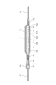
- FIG. 1 is a schematic diagram showing a configuration of a liquid-filled culture bag according to an embodiment of the present invention.
- FIG. 1 is a schematic cross-sectional view showing a configuration of a liquid-filled culture bag according to an embodiment of the present invention.
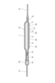
- FIG. 2 is a schematic cross-sectional view showing the configuration of a liquid-filled culture bag according to a first modified example of an embodiment of the present invention.
- FIG. 11 is a schematic cross-sectional view showing the configuration of a liquid-filled culture bag according to a second modified example of an embodiment of the present invention.
- FIG. 11 is a schematic cross-sectional view showing the configuration of a liquid-filled culture bag according to a third modified example of an embodiment of the present invention.
- FIG. 1 shows photographs illustrating the results of Test 1.
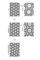
- FIG. 13 is a photograph showing the results of Test 2.
- FIG. 13 is a photograph showing the results of Test 3.
- FIG. 13 is a photograph showing the results of Test 4.
- the liquid-filled culture bag of this embodiment is a liquid-filled culture bag in which a culture bag having a microstructure formed in at least a part of the culture section is contained in an outer packaging section, and is characterized in that a space that can be reduced in pressure exists between the outside of the culture section and the outer packaging section, and the bag is degassed and packaged. That is, in this liquid-filled culture bag, a culture bag having a microstructure formed in at least a portion of the culture section is filled with liquid, and the culture bag is housed in an exterior packaging section.
- the liquid-filled culture bag of this embodiment comprises a culture bag 10 and an outer packaging part 20 , and the culture bag 10 is sealed within the outer packaging part 20 .
- the culture bag 10 is a bag-shaped container made of a soft packaging material for culturing cells or the like, and is provided with a culture section 11 therein having a culture surface which is an area for culturing cells.
- the outside of the culture unit 11 is the side opposite to the culture surface (the side provided with the first protrusion 112 in FIG. 2 ) in the bag wall portion (the bottom surface portion of the bag in FIG. 2 ) in which the culture unit 11 is provided.
- the outside of the culture unit 11 is a region corresponding to the culture surface on the outside of the culture bag 10.
- the culture section 11 is provided only on the bottom side of the culture bag 10, but the culture section 11 may be provided only on the top plate side of the culture bag 10, or on both the bottom side and the top plate side.
- the outside of the culture section 11 on the top plate side is the area corresponding to the culture surface on the top plate side on the outside of the culture bag 10
- the outside of the culture section 11 on the bottom side is the area corresponding to the culture surface on the bottom side on the outside of the culture bag 10.
- the culture bag 10 can be produced, for example, by sandwiching one or more ports between two pieces of film and heat sealing the periphery.
- the culture bag 10 has a bag seal 12 formed by heat sealing, one port 13, a tube 14 connected to the port 13, and a cap 15 that seals the tube 14.
- the method of producing the culture bag 10 is not limited to this, and it is also possible to produce the culture bag 10 by other methods, such as using a vacuum-pressure molded film or an inflation molded film.
- a microstructure 111 is formed in the culture section 11 of the culture bag 10.
- This microstructure 111 may be, for example, a number of recesses (wells) or a number of grooves.
- the culture section 11 having this microstructure 111 can be subjected to a low cell adhesion treatment or a cell adhesion treatment.
- the shape of the multiple recesses is not particularly limited, but can be, for example, a hemisphere, a cone, a pyramid, a shape consisting of a cylinder and a cone, or a shape consisting of a prism and a pyramid.
- the shape of the multiple grooves is also not particularly limited, but can be, for example, a V-shaped cross section perpendicular to the longitudinal direction of the groove, and can be linear or curved.
- the shape of the openings of the multiple recesses is preferably a circle, a square, or the like, and the diameter of the circle or inscribed circle can be, for example, 2 mm or less, or may be 1.5 mm or less, or may be 1.0 mm or less.
- the depth of the multiple recesses can be, for example, 1.5 mm or less, may be 1.0 mm or less, may be 0.5 mm or less, or may be 0.35 mm or less.
- the width and depth of the multiple grooves can each be, for example, 1.5 mm or less, 1.0 mm or less, 0.5 mm or less, or 0.35 mm or less.
- the microstructure 111 in the culture section 11 By forming the microstructure 111 in the culture section 11 into a plurality of recesses, it becomes possible to use the culture bag 10 to suitably form spheres consisting of a plurality of iPS cells or other adherent cells. Furthermore, by making the microstructure 111 in the culture section 11 into a plurality of grooves, it is possible to increase the area of the culture surface of the culture bag 10 and allow adherent cells to adhere to the culture section 11 and be cultured suitably.
- the culture bag 10 is filled with a liquid L.
- a liquid L it is preferable to use a culture medium, water for injection, a phosphate buffer solution, physiological saline, or the like.
- a culture medium water for injection, a phosphate buffer solution, physiological saline, or the like.
- the liquid-filled culture bag of this embodiment once air bubbles are removed from the microstructure 111 in the culture section 11 and the surface of the microstructure 111 becomes wet, air bubbles usually do not re-appear in the microstructure 111. For this reason, it is also preferable to fill the liquid L with not only the culture medium but also other liquids such as water for injection.
- the material in the region where the culture section 11 is provided is made of a gas-permeable material so that air bubbles accumulated in the microstructure 111 can be removed to the outside of the culture bag 10.
- the oxygen transmission rate at 37°C of the material in the region of the culture section 11 is preferably 3,000 ml/ m2 -day-atm or more, more preferably 5,000 ml/ m2 -day-atm or more, and even more preferably 8,000 ml/ m2 -day-atm or more.
- a space S that can be depressurized exists between the outside of the culture section 11 and the exterior packaging section 20 .
- the outside of the culture section 11 is the area corresponding to the culture surface on the outside of the culture bag 10 .
- the liquid-filled culture bag of this embodiment can be advantageously provided with a plurality of first protrusions 112 on the outside of the culture section 11, so that a reduced pressure space S is formed between the outside of the culture section 11 and the outer packaging section 20.
- the liquid-filled culture bag of this embodiment has a bottom portion of the culture bag 10 as a continuous U-shape, as shown in variant example 1 of Figure 3, and has both a recess (microstructure 111) inside the bag and a protrusion (first protrusion 112) outside the bag.
- the liquid-filled culture bag of this embodiment can also be provided with a plurality of second protrusions 22 in the area of the outer packaging section 20 facing the outside of the culture section 11, as shown in variant example 2 of Figure 4, so that a reduced pressure space S is preferably formed between the outside of the culture section 11 and the outer packaging section 20.
- the first protrusion 112 and the second protrusion 22 may be any protrusion capable of forming a reduced pressure space S between the outside of the culture section 11 and the outer packaging section 20, and there are no particular limitations on their shape, size, or number.
- liquid-filled culture bag of this embodiment may be double-packaged by enclosing the culture bag 10 in another outer packaging section and enclosing this outer packaging section in the outer packaging section 20. Even if the liquid-filled culture bag of this embodiment is configured in this manner, it is possible to effectively remove air bubbles from the culture section 11, for example, if the other outer packaging section performs the function of the spacer section 30 described above, thereby forming a reduced pressure space S between the outside of the culture section 11 and the outer packaging section 20.
- first protrusions 112 on the outside of the culture section 11 and multiple second protrusions 22 in the area of the outer packaging section 20 facing the outside of the culture section 11 it is also preferable to provide multiple first protrusions 112 on the outside of the culture section 11 and a spacer section 30 that forms a space between the outside of the culture section 11 and the outer packaging section 20 where the pressure can be reduced
- second protrusions 22 in the area of the outer packaging section 20 facing the outside of the culture section 11 and a spacer section 30 that forms a space between the outside of the culture section 11 and the outer packaging section 20 where the pressure can be reduced it is also preferable to have all of these configurations at the same time.
- the liquid-filled culture bag of this embodiment is degassed and packaged in a state in which the culture bag 10 is sealed in the outer packaging section 20 . That is, in the liquid-filled culture bag of this embodiment, the inside of the exterior packaging section 20 is in a vacuum or reduced pressure state, and is generally in a vacuum state.
- This vacuum packaging can be carried out using a commercially available heat sealing device, etc. For example, a commercial vacuum sealer manufactured by Fuji Impulse Co., Ltd. can be suitably used.
- an exterior sealing portion 21 is formed on the peripheral edge of the exterior packaging portion 20.
- the exterior packaging part 20 does not need to have gas barrier properties, but it is preferable that it has gas barrier properties. As described later in the examples, by using a material with gas barrier properties for the outer packaging portion 20, the time required to remove air bubbles accumulated in the microstructure 111 can be shortened compared to when a material without gas barrier properties is used.
- the oxygen permeability of the components of the area of the outer packaging section 20 facing the outside of the culture section 11 is preferably less than the oxygen permeability of the culture section 11, more preferably less than 8,000 ml/ m2 -day-atm, even more preferably less than 1,000 ml/ m2 -day-atm, and particularly preferably less than 100 ml/ m2 -day-atm.
- Test 3 it has been shown that even if the oxygen permeability of the film in the culture section and the oxygen permeability of the outer packaging section are the same, it takes time, but it is possible to remove air bubbles from the culture section. Furthermore, the more the oxygen permeability of the outer packaging section is set to be lower than the oxygen permeability of the film in the culture section and the greater the difference between them, the greater the amount of gas leaving the reduced pressure space S from the culture section side becomes compared to the amount of gas entering the reduced pressure space S from outside the outer packaging section, making it possible to shorten the time required to remove air bubbles that have accumulated in the culture section.
- the culture bag 10 is preferably made of a resin film, and polyolefin resins such as polyethylene, polypropylene, and polymethylpentene can be used.
- polyolefin resins such as polyethylene, polypropylene, and polymethylpentene
- polyethylene, copolymers of ethylene and ⁇ -olefin, copolymers of ethylene and vinyl acetate, ionomers using ethylene, acrylic acid or methacrylic acid copolymers, and metal ions can be used.
- Styrene-based elastomers, polyester-based thermoplastic elastomers, etc. can also be used.
- soft polyvinyl chloride resin polybutadiene resin, chlorinated polyethylene resin, polyurethane-based thermoplastic elastomers, silicone-based thermoplastic elastomers, styrene-based elastomers, such as SBS (styrene-butadiene-styrene), SIS (styrene-isoprene-styrene), SEBS (styrene-ethylene-butylene-styrene), SEPS (styrene-ethylene-propylene-styrene), and fluorine-based resins can also be used.
- SBS styrene-butadiene-styrene
- SIS styrene-isoprene-styrene
- SEBS styrene-ethylene-butylene-styrene
- SEPS styrene-ethylene-propylene-styrene
- the material of the exterior packaging part 20 can be, for example, polyethylene, polypropylene, a laminated film having a sealant layer and a barrier layer, or a vapor deposition film (barrier layer examples: ethylene-vinyl alcohol copolymer (EVOH), nylon, polyamide; vapor deposition examples: aluminum vapor deposition, alumina vapor deposition, silica vapor deposition, etc.).
- carrier layer examples ethylene-vinyl alcohol copolymer (EVOH), nylon, polyamide
- vapor deposition examples aluminum vapor deposition, alumina vapor deposition, silica vapor deposition, etc.
- the manufacturing method of the liquid-filled culture bag of the present embodiment is a manufacturing method of a liquid-filled culture bag in which a culture bag having a microstructure formed in at least a part of the culture section is contained in an outer packaging section, and is characterized in that a space that can be depressurized exists between the outside of the culture section and the outer packaging section, the culture bag is filled with liquid, and the culture bag is degassed and packaged.
- the manufacturing method of the liquid-filled culture bag of this embodiment is preferably a method in which a plurality of first protrusions are provided on the outside of the culture section, and/or a plurality of second protrusions are provided in an area of the outer packaging section facing the outside of the culture section, and/or a spacer section is provided that forms a space that can be depressurized between the outside of the culture section and the outer packaging section.
- the method of using the liquid-filled culture bag of this embodiment is the method of using the liquid-filled culture bag of this embodiment described above, characterized in that it is stored or transported at room temperature, refrigerated or frozen.
- the method of using the liquid-filled culture bag of this embodiment is a method of injecting the target cells, culture medium, cell adhesion factors, cytokines such as cell growth factors, etc. into the liquid-filled culture bag of this embodiment described above to perform culture.
- the culture bag can be stored or transported in a state where it is filled with liquid, and air bubbles can be removed during storage and transport.
- the liquid-filled culture bag of the present embodiment has air bubbles removed in advance, making it possible to perform cell culture suitably without the need to remove air bubbles from the recesses prior to cell culture.
- liquid-filled culture bag according to an embodiment of the present invention, the method for manufacturing the liquid-filled culture bag, and the test conducted to confirm the effect of removing air bubbles by using the liquid-filled culture bag.
- Tests were conducted to confirm that this embodiment can provide liquid-filled culture bags with no air bubbles. Specifically, first, a culture bag was prepared as shown in Figures 1 and 3. A polyethylene film (manufactured by Toyo Seikan Group Holdings, Ltd.) was used as the material for the culture bag, and two sheets of film measuring 100 mm x 70 mm x 0.10 mm were prepared.
- a polyethylene film manufactured by Toyo Seikan Group Holdings, Ltd.
- a plurality of hemispherical recesses were formed in the culture portion of the culture bag.
- the opening of the recesses had a diameter of 0.5 mm and a depth of 0.25 mm, and approximately 18,000 of these recesses were formed.
- the outer side of the culture area of the culture bag had hemispherical convex portions with a height of 250 ⁇ m and intervals of about 500 ⁇ m.
- the oxygen permeability of the film of the culture bag was 8,500 ml/ m2 ⁇ day ⁇ atm (37°C-50%RH).
- the film with the culture surface formed was attached to the other film by heat sealing.
- one port was formed, and a needleless connector (Qosina) was connected to this port via a tube.
- the prepared culture bag was filled with 15 mL of medium (StemFit AK02N (Ajinomoto Co., Inc., product number RCAK02N)), and only large air bubbles were removed by sucking them out with a syringe.
- the culture bag filled with the medium was then sealed in an outer packaging section (Co-pack® ST1525, Asahi Kasei Pax Corporation), and vacuum-packed using a commercially available vacuum sealer (V301, Fuji Impulse Corporation) to produce the liquid-filled culture bag of this embodiment.
- the film composition of the exterior packaging part was ONy#15/LDPE20/L-LDPE#40 (total 75 ⁇ m), and its oxygen permeability was 23 ml/m 2 ⁇ day ⁇ atm (23°C-50% RH).
- the resulting liquid-filled culture bag was then stored in a refrigerator at 4°C, and micrographs of the recesses on the culture surface of the liquid-filled culture bag were taken at the start of storage, after 2.5 hours, and after 5.5 hours. The results are shown in Figure 6.
- Test 2 A test was carried out to confirm that cell culture could be carried out using the liquid-filled culture bag obtained according to this embodiment. Specifically, the liquid-filled culture bag prepared in Test 1 was stored for three months and used to culture cells.
- the culture medium was completely removed from the liquid-filled culture bag that had been stored for three months, and the culture bag was filled with 20 ml of StemFit AK02N (Ajinomoto Co., Inc., product number RCAK02N) containing 10 mM Y-27632 (Wako Pure Chemical Industries, Ltd.), and human induced pluripotent stem (iPS) cells (1231A3 strain) were seeded so that each well contained approximately 150 cells.
- StemFit AK02N Alignomoto Co., Inc., product number RCAK02N
- 10 mM Y-27632 Wi-Fi Pure Chemical Industries, Ltd.
- iPS human induced pluripotent stem
- FIG. 7 shows the state of the culture surface before removing the medium from the liquid-filled culture bag stored for three months. As shown in this photograph, no air bubbles were present in the recesses of the culture surface.
- the upper and lower photographs in the center of FIG. 7 show the state of the culture surface at the start of culture (0 hr). In the enlarged view at the bottom, the multiple small particles in the recesses are cells.
- the top and bottom photographs on the right side of FIG. 7 show the state of the culture surface 24 hours (24 hr) after the start of culture, and spheroids can be observed to have been formed in the center of each well.
- Test 3 A test was carried out to confirm whether air bubbles are removed when a gas-permeable material is used as the material for the exterior packaging part of the liquid-filled culture bag of this embodiment. Specifically, first, the same culture bag was prepared as in Test 1. A polyethylene film (manufactured by Toyo Seikan Group Holdings, Ltd.) was used as the material for the culture bag, and two sheets of film measuring 100 mm x 70 mm x 0.10 mm were prepared.
- a plurality of semi-spherical recesses were formed on the culture surface of the culture bag.
- the opening of each recess had a diameter of 0.5 mm and a depth of 0.25 mm, and approximately 18,000 of these recesses were formed.
- the outer side of the culture area of the culture bag had hemispherical convex portions with a height of 250 ⁇ m and intervals of about 500 ⁇ m.
- the oxygen permeability of the film of the culture bag was 8,500 ml/ m2 ⁇ day ⁇ atm (37°C-50%RH).
- the film with the culture surface formed was attached to the other film by heat sealing.
- one port was formed, and a needleless connector (Qosina) was connected to this port via a tube.
- the prepared culture bag was filled with 15 mL of medium (StemFit AK02N (Ajinomoto Co., Inc., product number RCAK02N)), and only large air bubbles were removed by sucking them out with a syringe.
- the culture bag filled with the medium was then sealed in a gas-permeable outer packaging section, and vacuum packaging was performed using a commercially available vacuum sealer (V301, Fuji Impulse Co., Ltd.) to produce the liquid-filled culture bag of this embodiment.
- the outer packaging section was made of the same polyethylene film (manufactured by Toyo Seikan Group Holdings Co., Ltd.) used for the culture bag, which was heat-sealed to the same size as the Corpac® ST1525 used in Test 1.
- the oxygen permeability of the film for this outer packaging section was 8,500 ml/ m2 -day-atm (37°C-50% RH).
- the resulting liquid-filled culture bag was then stored in a refrigerator at 4°C, and micrographs of the recesses on the culture surface of the liquid-filled culture bag were taken at the start of storage, 2.5 hours, 6 hours, and 70 hours later. The results are shown in Figure 8.
- FIG. 8 The photograph of FIG. 8 taken at the start of storage (0 hr) shows air bubbles trapped within the black circle in the recess.
- the black circles in the recesses in the photographs taken 2.5 hours (2.5 hr) and 6 hours (6 hr) in FIG. 8 show that air bubbles are still trapped within the recesses.
- the photograph taken 70 hours later (70 hr) in FIG. 8 no black circles indicating air bubbles are visible in the recesses, and it is apparent that the air bubbles have been completely removed.
- the film with the culture surface formed was attached to the other film by heat sealing.
- one port was formed, and a needleless connector (Qosina) was connected to this port via a tube.
- the prepared culture bag was filled with 15 mL of medium (StemFit AK02N (Ajinomoto Co., Inc., product number RCAK02N)), and only large air bubbles were removed by sucking them out with a syringe.
- the culture bag filled with the medium was then sealed in an outer packaging section (Co-pack® ST1525, Asahi Kasei Pax Co., Ltd.) and packaged without degassing using a commercially available vacuum sealer (V301 Fuji Impulse Co., Ltd.) to produce a liquid-filled culture bag as a comparative example.
- the obtained liquid-filled culture bag of the comparative example was stored in a refrigerator at 4° C., and micrographs of the recesses on the culture surface of the liquid-filled culture bag were taken at the start of storage, and after 2.5 hours, 6 hours, and 70 hours. The results are shown in FIG.
- FIG. 9 taken 6 hours (6 hr) and 70 hours (70 hr) also show air bubbles trapped within the black circles in the recesses.
- simply packaging and storing the culture bag without providing a space that can be depressurized between the outside of the culture section of the culture bag and the outer packaging section cannot remove the air bubbles in the microstructure formed in the culture section of the culture bag.
- a culture bag of a size capable of forming, for example, 500,000 to 1,000,000 spheres can be selected, and this can be sealed in an outer packaging section to produce a liquid-filled culture bag.
- the present invention can be suitably used when using a liquid-filled culture bag in which culture medium or the like has been filled in advance and air bubbles have been removed from the culture area.
Landscapes
- Health & Medical Sciences (AREA)
- Engineering & Computer Science (AREA)
- Life Sciences & Earth Sciences (AREA)
- Zoology (AREA)
- Organic Chemistry (AREA)
- Bioinformatics & Cheminformatics (AREA)
- Chemical & Material Sciences (AREA)
- Wood Science & Technology (AREA)
- Biomedical Technology (AREA)
- Genetics & Genomics (AREA)
- Biotechnology (AREA)
- General Health & Medical Sciences (AREA)
- Biochemistry (AREA)
- General Engineering & Computer Science (AREA)
- Microbiology (AREA)
- Sustainable Development (AREA)
- Clinical Laboratory Science (AREA)
- Cell Biology (AREA)
- Virology (AREA)
- Apparatus Associated With Microorganisms And Enzymes (AREA)
- Micro-Organisms Or Cultivation Processes Thereof (AREA)
Abstract
Description
また、この方法は開放系の容器にのみ可能な方法であり、培養バッグ内の培養部に溜まった気泡の除去に適するものではなかった。
また、特許文献2には、培養部に微小凹部を備えた培養バッグに脱気した培地充填液を充填することによって、微小凹部に溜まった気泡を除去することが開示されている。さらに、この文献には、培養部に微小凹部を備えた培養バッグを真空排気装置に配置して真空にさらすことにより、培養バッグ内から空気を除去することも開示されている。
すなわち、本発明は、上記事情に鑑みてなされたものであり、多くの手間や専用の設備を要することなく、培養バッグ内の微小凹部に溜まった気泡を効率よく除去することができ、製造現場での煩わしい作業やコンタミネーションのリスクを低減することが可能な液体充填済み培養バッグ、液体充填済み培養バッグの製造方法、及び液体充填済み培養バッグの使用方法の提供を目的とする。
また、本発明の液体充填済み培養バッグを、前記培養バッグにおける前記培養部が備えられた領域の部材の酸素透過度が、3,000ml/m2・day・atm以上である構成とすることが好ましい。
さらに、本発明の液体充填済み培養バッグを、上記の液体充填済み培養バッグを様々に組み合わせた構成とすることも好ましい。
また、本発明の液体充填済み培養バッグの使用方法は、上記の液体充填済み培養バッグの使用方法であって、前記液体充填済み培養バッグに、細胞や培地、細胞接着因子、細胞増殖因子等のサイトカイン類を注入して培養を行う方法としてある。
本実施形態の液体充填済み培養バッグは、培養部の少なくとも一部に微細構造が形成された培養バッグが外装包装部に収容された液体充填済み培養バッグであって、培養部の外側と外装包装部の間に減圧可能な空間が存在し、脱気包装されていることを特徴とする。
すなわち、この液体充填済み培養バッグは、培養部の少なくとも一部に微細構造が形成された培養バッグに液体が充填され、その培養バッグが外装包装部に収容されている。
培養バッグ10は、細胞などを培養するための軟包材からなる袋状の容器であり、その内部に細胞を培養する領域である培養面を有する培養部11を備えている。
培養部11の外側とは、培養部11が備えられたバッグ壁部(図2ではバッグの底面部)における培養面の反対側(図2では第一突起部112が備えられた側)である。すなわち、培養部11の外側とは、培養バッグ10の外側における培養面に対応する領域である。
さらに、チューブ14の封止はキャップ15による方法に限定されず、例えばキャップ機能を有するコネクタを用いてチューブ14を封止したり、チューブ14に一般的なコネクタを接続し、コネクタを封止するキャップを備えるようにしてもよい。
また、複数の凹部の深さは、例えば1.5mm以下にすることができ、1.0mm以下にしてもよく、0.5mm以下にしてもよく、0.35mm以下にしてもよい。
さらに、複数の溝の幅及び深さも同様に、それぞれ例えば1.5mm以下にすることができ、1.0mm以下にしてもよく、0.5mm以下にしてもよく、0.35mm以下にしてもよい。
また、培養部11における微細構造111を複数の溝とすることにより、培養バッグ10の培養面の面積を増大させた状態で、接着細胞を培養部11に接着させて好適に培養することが可能となる。
本実施形態の液体充填済み培養バッグは、培養部11における微細構造111から一旦気泡が除去されて微細構造111の表面が濡れてしまうと、通常、微細構造111に再び気泡が生じることがない。このため、液体Lとして、培地のみならず、注射用水などの他の液体を充填しておくことも好ましい。
培養部11の外側とは、上記のとおり、培養バッグ10の外側における培養面に対応する領域である。
また、本実施形態の液体充填済み培養バッグを、図3の変形例1に示すように、培養バッグ10の底面部がU字形状の連続体として、バッグ内の凹部(微細構造111)とバッグ外の凸部(第一突起部112)とが兼ね備わった形状とすることも好ましい。
第一突起部112及び第二突起部22は、培養部11の外側と外装包装部20の間に減圧空間Sを形成可能なものであればよく、その形状やサイズ、個数については、特に限定されない。
スペーサー部30は、培養部11の外側と外装包装部20の間に減圧可能な空間を形成できるものであればよく、その具体的な構造は特に限定されないが、例えば、複数の貫通孔を備えた板状部材や多孔質部材などを好適に用いることが可能である。
本実施形態の液体充填済み培養バッグをこのようにしても、例えばその他の外装包装部が上述したスペーサー部30の機能を果たし、それによって培養部11の外側と外装包装部20の間に減圧空間Sが形成されたものとする場合には、培養部11から気泡を好適に除去することが可能である。
すなわち、本実施形態の液体充填済み培養バッグにおいて、外装包装部20内は、真空乃至減圧の状態となっており、概ね真空状態となっている。
この脱気包装は、市販のヒートシール器具などを用いて行うことができる。例えば、富士インパルス株式会社製の業務用の脱気シーラーなどを好適に用いることが可能である。
本実施形態の液体充填済み培養バッグにおいて、外装包装部20の周縁部には、外装封止部21が形成されている。
実施例において後述するように、外装包装部20にガスバリア性を有する材料を用いることにより、ガスバリア性を有していないものを用いる場合に比較して、微細構造111に溜まった気泡を除去する時間を短縮することができるためである。
また、本実施形態の液体充填済み培養バッグの製造方法は、培養部の外側に複数の第一突起部が備えられ、及び/又は、外装包装部における培養部の外側に対面する領域に複数の第二突起部が備えられ、及び/又は、培養部の外側と外装包装部の間に減圧可能な空間を形成するスペーサー部が備えられた方法とすることが好ましい。
また、培養部の外側と外装包装部の間に減圧可能な空間を設けて、培養バッグに液体を充填した状態で培養バッグを脱気包装することにより、培養バッグからの液漏れのチェックを行うことも可能になっている。
また、本実施形態の液体充填済み培養バッグの使用方法を、上述した本実施形態の液体充填済み培養バッグに、目的の細胞や培地、細胞接着因子、細胞増殖因子等のサイトカイン類を注入して培養を行う方法とすることも好ましい。
さらに、充填済みの液体を培養バッグから一旦除去した後、目的の細胞や培地類を注入して培養を行う方法とすることも好ましい。
そして、このような使用方法における本実施形態の液体充填済み培養バッグは、気泡が予め除去されているため、細胞培養に先立って凹部から気泡の除去作業を行うことなく、細胞培養を好適に行うことが可能になっている。
本実施形態によって、気泡が除去された液体充填済み培養バッグを得ることができることを確認するための試験を行った。
具体的には、まず図1及び図3に示す培養バッグを作製した。培養バッグの材料としてポリエチレン製フィルム(東洋製罐グループホールディングス株式会社製)を使用し、100mm×70mm×0.10mmの2枚のフィルムを作成した。
培養バッグの培養部の外側には、半球状で高さが250μm、間隔が約500μmの凸部を形成した。また、培養バッグのフィルムの酸素透過度は8,500ml/m2・day・atm(37℃-50%RH)であった。
そして、培地を充填した培養バッグを外装包装部(コーパック(R)ST1525,旭化成パックス株式会社)に封入し、市販の脱気シーラー(V301,富士インパルス株式会社)を用いて脱気包装を行って、本実施形態の液体充填済み培養バッグを製造した。
外装包装部のフィルムの構成は、ONy#15/LDPE20/L-LDPE#40(計75μm)であり、その酸素透過度は、23ml/m2・day・atm(23℃-50%RH)であった。
次に、図6の2.5時間後(2.5hr)の写真の凹部において、略三日月状の粒が写っているが、これは小さくなった気泡であり、部分的に気泡が除去されていることが分かる。なお、この写真には結露によって生じた外部の水滴が映り込んでいる。
この結果から、本実施形態によれば、気泡が除去された液体充填済み培養バッグが好適に得られることが分かった。
本実施形態によって得られた液体充填済み培養バッグを使用して、細胞培養が行えることを確認するための試験を行った。
具体的には、試験1で作製した液体充填済み培養バッグを3ヶ月間保管したものを使用して、細胞培養を行った。
図7の左端の写真は、3ヶ月間保管した液体充填済み培養バッグから培地を除去する前の培養面の状態を示している。この写真に示されるように、培養面の凹部に気泡は存在していなかった。
図7の右端の上下の写真は、培養開始から24時間後(24hr)の培養面の状態を示しており、各凹部内の中央にスフェロイドが形成されている様子が観察される。
本実施形態の液体充填済み培養バッグの外装包装部の材料として、ガス透過性を有するものを用いた場合に、気泡が除去されるかを確認するための試験を行った。
具体的には、まず試験1と同じ培養バッグを作製した。培養バッグの材料としてポリエチレン製フィルム(東洋製罐グループホールディングス株式会社製)を使用し、100mm×70mm×0.10mmの2枚のフィルムを作成した。
培養バッグの培養部の外側には、半球状で高さが250μm、間隔が約500μmの凸部を形成した。また、培養バッグのフィルムの酸素透過度は8,500ml/m2・day・atm(37℃-50%RH)であった。
そして、培地を充填した培養バッグをガス透過性を有する外装包装部に封入し、市販の脱気シーラー(V301,富士インパルス株式会社)を用いて脱気包装を行って、本実施形態の液体充填済み培養バッグを製造した。外装包装部としては、培養バッグに使用したものと同じポリエチレン製フィルム(東洋製罐グループホールディングス株式会社製)を試験1で用いたコーパック(R)ST1525と同サイズにヒートシールにより製袋したものを使用した。この外装包装部のフィルムの酸素透過度は、8,500ml/m2・day・atm(37℃-50%RH)であった。
また、図8の2.5時間後(2.5hr)と6時間後(6hr)の写真の凹部における黒い円内には、まだ気泡が溜まっている状態が示されている。
一方、図8の70時間後(70hr)の写真の凹部には気泡を示す黒い円が写っておらず、気泡が完全に除去されていることが観察される。
この結果から、本実施形態の液体充填済み培養バッグの外装包装部の材料として、ガス透過性を有するものを用いた場合、ガスバリア性を有するものを用いた場合に比較して、気泡の除去に時間がかかるものの、気泡は除去されることが確認された。
本実施形態の液体充填済み培養バッグを用いることなく、培養バッグを保管した場合に、気泡が除去された液体充填済み培養バッグを得ることができるか否かを確認するための試験を行った。
具体的には、まず試験1と同じ培養バッグを作製した。培養バッグの材料としてポリエチレン製フィルム(東洋製罐グループホールディングス株式会社製)を使用し、100mm×70mm×0.10mmの2枚のフィルムを作成した。
培養バッグの培養部の外側には、半球状で高さが250μm、間隔が約500μmの凸部を形成した。また、培養バッグのフィルムの酸素透過度は8,500ml/m2・day・atm(37℃-50%RH)であった。
そして、培地を充填した培養バッグを外装包装部(コーパック(R)ST1525,旭化成パックス株式会社)に封入し、市販の脱気シーラー(V301富士インパルス株式会社)を用いて脱気せずに包装し、比較例としての液体充填済み培養バッグを製造した。
次いで、得られた比較例の液体充填済み培養バッグを冷蔵庫にて4℃で保管し、保管開始時点、及び2.5時間後、6時間後、及び70時間後における液体充填済み培養バッグの培養面の凹部の顕微鏡写真を撮影した。その結果を図9に示す。
また、図9の2.5時間後(2.5hr)の写真の凹部においても、黒い円内に気泡が溜まっている状態が示されている。
このように、培養バッグの培養部の外側と外装包装部の間に減圧可能な空間を設けることなく、単に培養バッグを包装・保管したのみでは、培養バッグの培養部に形成された微細構造における気泡は除去できないことが分かった。
例えば、培養バッグとして例えば50万個~100万個のスフェアを形成可能な大きさのものを選択し、これを外装包装部に封止して液体充填済み培養バッグを製造するなど適宜変更することが可能である。
11 培養部
111 微細構造
112 第一突起部
12 バッグ封止部
13 ポート
14 チューブ
15 キャップ
20 外装包装部
21 外装封止部
22 第二突起部
30 スペーサー部
S 減圧空間
L 液体
Claims (12)
- 培養部の少なくとも一部に微細構造が形成された培養バッグが外装包装部に収容された液体充填済み培養バッグであって、前記培養部の外側と前記外装包装部の間に減圧可能な空間が存在し、脱気包装されていることを特徴とする液体充填済み培養バッグ。
- 前記培養部の外側に複数の第一突起部が備えられたことを特徴とする請求項1記載の液体充填済み培養バッグ。
- 前記外装包装部における前記培養部の外側に対面する領域に複数の第二突起部が備えられたことを特徴とする請求項1又は2記載の液体充填済み培養バッグ。
- 前記培養部の外側と前記外装包装部の間に減圧可能な空間を形成するスペーサー部が備えられたことを特徴とする請求項1又は2記載の液体充填済み培養バッグ。
- 前記微細構造が、複数の凹部又は複数の溝であることを特徴とする請求項1又は2記載の液体充填済み培養バッグ。
- 前記培養バッグにおける前記培養部が備えられた領域の部材の酸素透過度が、3,000ml/m2・day・atm以上であることを特徴とする請求項1又は2記載の液体充填済み培養バッグ。
- 前記外装包装部における前記培養部の外側に対面する領域の部材の酸素透過度が、前記培養部の酸素透過度以下であることを特徴とする請求項1又は2記載の液体充填済み培養バッグ。
- 前記外装包装部における前記培養部の外側に対面する領域の部材の酸素透過度が、1,000ml/m2・day・atm以下のガスバリア性を有することを特徴とする請求項7記載の液体充填済み培養バッグ。
- 培養部の少なくとも一部に微細構造が形成された培養バッグが外装包装部に収容された液体充填済み培養バッグの製造方法であって、
前記培養部の外側と前記外装包装部の間に減圧可能な空間が存在し、
前記培養バッグに液体を充填し、
前記培養バッグを脱気包装する
ことを特徴とする液体充填済み培養バッグの製造方法。 - 前記培養部の外側に複数の第一突起部が備えられ、及び/又は、前記外装包装部における前記培養部の外側に対面する領域に複数の第二突起部が備えられ、及び/又は、前記培養部の外側と前記外装包装部の間に減圧可能な空間を形成するスペーサー部が備えられた
ことを特徴とする請求項9記載の液体充填済み培養バッグの製造方法。 - 請求項1又は2記載の液体充填済み培養バッグの使用方法であって、
常温又は冷蔵若しくは冷凍で、保管し又は輸送する
ことを特徴とする液体充填済み培養バッグの使用方法。 - 請求項1又は2記載の液体充填済み培養バッグの使用方法であって、
前記液体充填済み培養バッグに、細胞や培地、細胞接着因子、細胞増殖因子等のサイトカイン類を注入して培養を行う
ことを特徴とする液体充填済み培養バッグの使用方法。
Priority Applications (3)
| Application Number | Priority Date | Filing Date | Title |
|---|---|---|---|
| EP24831710.9A EP4737555A1 (en) | 2023-06-27 | 2024-06-14 | Liquid-filled culture bag, method for producing liquid-filled culture bag, and method for using liquid-filled culture bag |
| CN202480022120.3A CN120936705A (zh) | 2023-06-27 | 2024-06-14 | 充液完成培养袋、充液完成培养袋的制造方法以及充液完成培养袋的使用方法 |
| US19/361,080 US20260042986A1 (en) | 2023-06-27 | 2025-10-17 | Liquid-filled culture bag, method for producing liquid-filled culture bag, and method for using liquid-filled culture bag |
Applications Claiming Priority (2)
| Application Number | Priority Date | Filing Date | Title |
|---|---|---|---|
| JP2023105009A JP2025005027A (ja) | 2023-06-27 | 2023-06-27 | 液体充填済み培養バッグ、液体充填済み培養バッグの製造方法、及び液体充填済み培養バッグの使用方法 |
| JP2023-105009 | 2023-06-27 |
Publications (1)
| Publication Number | Publication Date |
|---|---|
| WO2025004845A1 true WO2025004845A1 (ja) | 2025-01-02 |
Family
ID=93938872
Family Applications (1)
| Application Number | Title | Priority Date | Filing Date |
|---|---|---|---|
| PCT/JP2024/021622 Ceased WO2025004845A1 (ja) | 2023-06-27 | 2024-06-14 | 液体充填済み培養バッグ、液体充填済み培養バッグの製造方法、及び液体充填済み培養バッグの使用方法 |
Country Status (5)
| Country | Link |
|---|---|
| US (1) | US20260042986A1 (ja) |
| EP (1) | EP4737555A1 (ja) |
| JP (1) | JP2025005027A (ja) |
| CN (1) | CN120936705A (ja) |
| WO (1) | WO2025004845A1 (ja) |
Citations (6)
| Publication number | Priority date | Publication date | Assignee | Title |
|---|---|---|---|---|
| JPH03172169A (ja) * | 1989-11-30 | 1991-07-25 | Koojin Bio Kk | 保存兼組織培養用容器 |
| JP2005323588A (ja) * | 2004-04-13 | 2005-11-24 | Toyo Seikan Kaisha Ltd | 培養二重容器および培養方法 |
| JP2012239401A (ja) * | 2011-05-17 | 2012-12-10 | Toyo Seikan Kaisha Ltd | 細胞培養方法、及び細胞培養システム |
| WO2013114845A1 (ja) * | 2012-02-01 | 2013-08-08 | 東洋製罐グループホールディングス株式会社 | 細胞培養用キット、及び細胞培養用キットの使用方法 |
| WO2021241665A1 (ja) * | 2020-05-28 | 2021-12-02 | 東洋製罐グループホールディングス株式会社 | 細胞培養バッグ内の空気を除去することを含む細胞培養システム |
| JP2022016210A (ja) * | 2020-07-11 | 2022-01-21 | 東洋製罐グループホールディングス株式会社 | 細胞培養容器、細胞培養容器の製造方法、細胞の製造方法、及び細胞培養装置 |
-
2023
- 2023-06-27 JP JP2023105009A patent/JP2025005027A/ja active Pending
-
2024
- 2024-06-14 EP EP24831710.9A patent/EP4737555A1/en active Pending
- 2024-06-14 CN CN202480022120.3A patent/CN120936705A/zh active Pending
- 2024-06-14 WO PCT/JP2024/021622 patent/WO2025004845A1/ja not_active Ceased
-
2025
- 2025-10-17 US US19/361,080 patent/US20260042986A1/en active Pending
Patent Citations (6)
| Publication number | Priority date | Publication date | Assignee | Title |
|---|---|---|---|---|
| JPH03172169A (ja) * | 1989-11-30 | 1991-07-25 | Koojin Bio Kk | 保存兼組織培養用容器 |
| JP2005323588A (ja) * | 2004-04-13 | 2005-11-24 | Toyo Seikan Kaisha Ltd | 培養二重容器および培養方法 |
| JP2012239401A (ja) * | 2011-05-17 | 2012-12-10 | Toyo Seikan Kaisha Ltd | 細胞培養方法、及び細胞培養システム |
| WO2013114845A1 (ja) * | 2012-02-01 | 2013-08-08 | 東洋製罐グループホールディングス株式会社 | 細胞培養用キット、及び細胞培養用キットの使用方法 |
| WO2021241665A1 (ja) * | 2020-05-28 | 2021-12-02 | 東洋製罐グループホールディングス株式会社 | 細胞培養バッグ内の空気を除去することを含む細胞培養システム |
| JP2022016210A (ja) * | 2020-07-11 | 2022-01-21 | 東洋製罐グループホールディングス株式会社 | 細胞培養容器、細胞培養容器の製造方法、細胞の製造方法、及び細胞培養装置 |
Also Published As
| Publication number | Publication date |
|---|---|
| JP2025005027A (ja) | 2025-01-16 |
| EP4737555A1 (en) | 2026-05-06 |
| US20260042986A1 (en) | 2026-02-12 |
| CN120936705A (zh) | 2025-11-11 |
Similar Documents
| Publication | Publication Date | Title |
|---|---|---|
| JP5098471B2 (ja) | 細胞培養用トレイ状容器並びに同容器への収容物の充填方法 | |
| KR100850733B1 (ko) | 이중 배양 용기 및 배양 방법 | |
| JP6613558B2 (ja) | 細胞培養容器、培地入細胞培養容器および細胞の培養方法 | |
| CN107750272A (zh) | 用于繁殖细胞的系统 | |
| JP2014503426A (ja) | ブリスタ包装材に液体を充填する方法及び液体を充填するためのキャビティを備えたブリスタ包装材 | |
| US8979817B2 (en) | Multi-chamber container with seal breach detection | |
| TW201738369A (zh) | 細胞培養容器,細胞培養容器的支撐型架及細胞培養方法 | |
| JP4665588B2 (ja) | 培養二重容器および培養方法 | |
| JP7322384B2 (ja) | 培地充填液、培地充填方法、培養容器、及び培地充填用気泡除去装置 | |
| JP2007175028A (ja) | 閉鎖系細胞培養容器、閉鎖系細胞培養用キット、及び閉鎖系細胞培養容器の製造方法 | |
| WO2025004845A1 (ja) | 液体充填済み培養バッグ、液体充填済み培養バッグの製造方法、及び液体充填済み培養バッグの使用方法 | |
| CN101326279A (zh) | 培养容器和培养方法 | |
| JP2007020710A (ja) | 医療用容器梱包体 | |
| WO2021014642A1 (ja) | 培養液収容容器 | |
| JP4706327B2 (ja) | 細胞培養容器 | |
| JP6834181B2 (ja) | 凍結用複室容器 | |
| JPH119659A (ja) | 医療用容器 | |
| CN202366163U (zh) | 一种碳酸氢钠注射液塑料瓶包装 | |
| US20220315879A1 (en) | Adherent cell culture vessel, and method for producing adherent cell culture vessel | |
| JP4802875B2 (ja) | 細胞培養容器及び細胞移注方法 | |
| JP2008022715A (ja) | 細胞シート培養方法及び細胞培養容器 | |
| CN103156770A (zh) | 一种大容量粉液袋容器的生产方法 | |
| EP4180512A1 (en) | Cell culturing container, method for manufacturing cell culturing container, cell production method, cell culturing device, and cell culturing jig | |
| CN103230338B (zh) | 一种稳定碳酸氢钠注射液产品质量的方法 | |
| CN103142409B (zh) | 一种塑瓶或软袋注射液产品质量的保证方法 |
Legal Events
| Date | Code | Title | Description |
|---|---|---|---|
| 121 | Ep: the epo has been informed by wipo that ep was designated in this application |
Ref document number: 24831710 Country of ref document: EP Kind code of ref document: A1 |
|
| WWE | Wipo information: entry into national phase |
Ref document number: CN2024800221203 Country of ref document: CN |
|
| WWE | Wipo information: entry into national phase |
Ref document number: 2024831710 Country of ref document: EP |
|
| NENP | Non-entry into the national phase |
Ref country code: DE |
|
| ENP | Entry into the national phase |
Ref document number: 2024831710 Country of ref document: EP Effective date: 20260127 |
|
| ENP | Entry into the national phase |
Ref document number: 2024831710 Country of ref document: EP Effective date: 20260127 |