WO2025004775A1 - ワイヤハーネス、およびホルダ - Google Patents
ワイヤハーネス、およびホルダ Download PDFInfo
- Publication number
- WO2025004775A1 WO2025004775A1 PCT/JP2024/021006 JP2024021006W WO2025004775A1 WO 2025004775 A1 WO2025004775 A1 WO 2025004775A1 JP 2024021006 W JP2024021006 W JP 2024021006W WO 2025004775 A1 WO2025004775 A1 WO 2025004775A1
- Authority
- WO
- WIPO (PCT)
- Prior art keywords
- holder
- tube
- tape
- electric wire
- wire
- Prior art date
- Legal status (The legal status is an assumption and is not a legal conclusion. Google has not performed a legal analysis and makes no representation as to the accuracy of the status listed.)
- Ceased
Links
Images






Classifications
-
- H—ELECTRICITY
- H01—ELECTRIC ELEMENTS
- H01B—CABLES; CONDUCTORS; INSULATORS; SELECTION OF MATERIALS FOR THEIR CONDUCTIVE, INSULATING OR DIELECTRIC PROPERTIES
- H01B7/00—Insulated conductors or cables characterised by their form
-
- H—ELECTRICITY
- H02—GENERATION; CONVERSION OR DISTRIBUTION OF ELECTRIC POWER
- H02G—INSTALLATION OF ELECTRIC CABLES OR LINES, OR OF COMBINED OPTICAL AND ELECTRIC CABLES OR LINES
- H02G3/00—Installations of electric cables or lines or protective tubing therefor in or on buildings, equivalent structures or vehicles
- H02G3/02—Details
- H02G3/04—Protective tubing or conduits, e.g. cable ladders or cable troughs
Definitions
- the present invention relates to a wire harness and a holder.
- a wire harness is known in which the ends of the corrugated tube are wrapped with tape to secure the electric wires covered with the corrugated tube to the corrugated tube. This prevents the corrugated tube from shifting out of position relative to the electric wires.
- the objective of this disclosure is to provide a wire harness and holder that are less likely to cause the appearance of the tube ends to deteriorate.
- the wire harness that solves the above problem includes electric wires, a flexible tube that houses the electric wires, a holder that is attached to close the end of the tube, and tape that is wound spirally around the end of the tube and the holder to secure the holder to the tube, and the holder has a tape attachment portion that is shaped so that the winding diameter of the tape is smaller at a position farther from the tube than at a position closer to the tube.
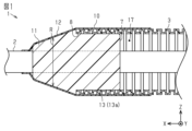
- FIG. 1 is a cross-sectional view taken along line II shown in FIG. 2 according to the first embodiment.
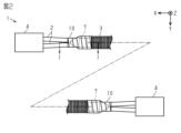
- FIG. 2 is an explanatory diagram showing an outline of the entire wire harness.
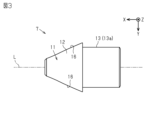
- FIG. 3 is a plan view of the holder.
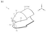
- FIG. 4 is a perspective view of the holder.
- FIG. 5 is a side view of the holder.
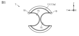
- FIG. 6 is a rear view of the holder.
- FIG. 7 is a front view of the holder.
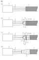
- 8(a) to 8(d) are process diagrams showing the procedure for assembling the wire harness.
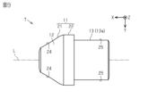
- FIG. 9 is a plan view of the holder according to the second embodiment.
- FIG. 10 is a perspective view of the holder.
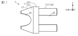
- FIG. 11 is a side view of the holder.
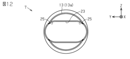
- FIG. 12 is a rear view of the holder.
- FIG. 10 is a perspective view of the holder.
- FIG. 13 is a front view of the holder.
- 14(a) to 14(f) are process diagrams showing the procedure for assembling the wire harness.
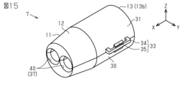
- FIG. 15 is a perspective view of a holder according to the third embodiment.
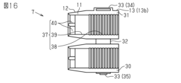
- FIG. 16 is an inside view of the holder in the open state.
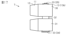
- FIG. 17 is an exterior view of the holder in an open state.
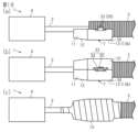
- 18(a) to 18(c) are process diagrams showing the assembly procedure of the wire harness.
- FIG. 19 is a perspective view of a holder according to a modified example.
- a wire harness according to the present disclosure comprises electric wires, a flexible tube that houses the electric wires, a holder that is attached to cover an end of the tube, and a tape that is spirally wound around the end of the tube and the holder to secure the holder to the tube, the holder having a tape attachment portion that is shaped so that the winding diameter of the tape is smaller at a position farther from the tube than at a position closer to the tube.
- the tape attachment portion is formed with an inclined outer surface that slopes downward toward the end of the electric wire, and the tape is wound around the inclined surface of the tape attachment portion.
- the tape wrapped around the inclined surface of the holder makes it possible to hide the space between the electric wire and the tube.
- the tape is wrapped around the inclined surface of the holder, it is easy to wrap the tape around it.
- the holder has a wire insertion portion with an open side. With this configuration, it is possible to attach the holder to the wire to which the connector is attached by retrofitting it. When the holder is of this retrofit type, the parts can be attached in a versatile order, which contributes to improving workability.
- the holder has a hole-shaped electric wire insertion portion into which the electric wire is inserted. According to this configuration, after the electric wire is passed through the hole-shaped electric wire insertion portion of the holder, a connector is attached to the electric wire.
- the electric wire is supported by the wall of the hole-shaped electric wire insertion portion, making it possible to prevent the electric wire from becoming misaligned.
- the tape is wound around the electric wire, the tube, and the holder.
- the electric wire, the tube, and the holder are fixed together by the tape, making it possible to suppress misalignment between these components.
- the holder has a fitting portion that fits onto the end of the tube. With this configuration, it is possible to wrap tape around the outer surfaces of the tube and the holder while the fitting portion of the holder is fitted onto the end of the tube. This contributes to improving the workability of wrapping the tape.
- the fitting portion is an inner fitting portion that fits inside an opening provided at the end of the tube.
- the fitting portion is an outer fitting portion that fits onto the outer surface of the end portion of the tube. With this configuration, it is possible to cover and protect the tip of the tube with the outer fitting portion.
- the holder of the present disclosure is attached to the end of a cylindrical tube that houses electric wires so as to close the end of the tube.
- the holder has a tape attachment portion that is formed in a shape such that, when the holder is fixed to the end of the tube with a spirally wound tape, the winding diameter of the tape is smaller at a position farther from the tube than at a position closer to the tube. With this configuration, it is possible to obtain the same effect as that of a wire harness.
- the wire harness 1 includes an electric wire 2 and a flexible tube 3 that houses the electric wire 2.
- the electric wire 2 has an electric wire structure in which, for example, a core wire is covered with an insulating coating.
- a core wire is covered with an insulating coating.
- a metal material such as a copper-based or aluminum-based material is used as the material of the core wire.
- an insulating material such as a synthetic resin is used as the material of the insulating coating.
- a synthetic resin mainly composed of a polyolefin-based resin such as cross-linked polyethylene or cross-linked polypropylene is used as the material of the insulating coating.
- multiple electric wires 2 are provided.
- the two electric wires 2 are arranged side by side in a plan view.
- the number of electric wires 2 is not limited to multiple, and may be one.
- the electric wire 2 may have, for example, an electromagnetically shielded structure or a non-electromagnetically shielded structure.
- the tube 3 is, for example, a corrugated tube having a bellows structure in which convex portions and concave portions are alternately arranged along the length direction (the X-axis direction in FIG. 2).
- the material for the tube 3 is, for example, a non-conductive resin material or a conductive resin material.
- the resin material is, for example, a synthetic resin such as polyolefin, polyamide, polyester, or ABS resin.
- the electric wires 2 are exposed from both ends of the tube 3.
- a connector 4 is connected to each end of the electric wires 2 exposed from the tube 3.
- the connector 4 may be, for example, a square connector or a round connector.
- the connector 4 may be, for example, a round terminal or any other terminal.
- the wire harness 1 includes a holder 7 attached to close the end of the tube 3.
- the holder 7 is attached to an opening 8 provided at the end of the tube 3.
- the holder 7 is provided to support the electric wires 2 while closing a space 17 between the electric wires 2 and the tube 3.
- the holder 7 protects the electric wires 2 by preventing the electric wires 2 from contacting the edge of the tube 3.
- the holders 7 in this example are attached to both ends of the tube 3 (see Fig. 2).
- the material of the holder 7 is, for example, a resin such as polyethylene or polypropylene.
- the material of the holder 7 is not limited to resin, and may be rubber.
- the wire harness 1 includes a tape 10 that fixes the holder 7 to the tube 3.
- the tape 10 is spirally wound around the end of the tube 3 and the holder 7, thereby fixing the holder 7 to the tube 3.
- the tape 10 is, for example, an adhesive tape having an adhesive material applied to one side.
- the base material of the adhesive tape may be, for example, polyvinyl chloride, polyester, nonwoven fabric, or the like.
- the adhesive material may be, for example, a rubber-based, acrylic-based, silicone-based, or the like.
- the holder 7 has a tape attachment portion 11 formed in a shape such that the winding diameter R of the tape 10 is smaller at a position farther from the tube 3 (a position closer to the +X axis in FIG. 3, etc.) than at a position closer to the tube 3 (a position closer to the -X axis in FIG. 3, etc.).
- the tape attachment portion 11 is formed in an inclined shape with the outer surface descending toward the end of the electric wire 2 (the +X axis direction in FIG. 3, etc.).
- the tape 10 is wound around an inclined surface 12 of the tape attachment portion 11.
- the inclined surface 12 is formed to be inclined with respect to the axis L of the holder 7.
- the holder 7 has a fitting portion 13 that fits into the end of the tube 3.
- the fitting portion 13 is an inner fitting portion 13a that fits into the inside of the opening 8 provided at the end of the tube 3.
- the outer peripheral surface of the inner fitting portion 13a is curved to fit along the inner peripheral surface of the opening 8 of the tube 3.
- the holder 7 has an electric wire insertion section 15 with an open side.
- the electric wire insertion section 15 is provided to accommodate the electric wire 2.
- the holder 7 has an electric wire insertion section 15 with an open side, it is an add-on type that can be attached to the wire harness 1 to which the tube 3 and the connector 4 are assembled.
- the electric wire insertion sections 15 are provided so as to face each other about the axis of the holder 7.
- the inner surface of the electric wire insertion section 15 is formed in a curved shape so as to fit the surface of the electric wire 2.
- the electric wire insertion section 15 is formed across both the tape attachment section 11 and the fitting section 13.
- the holder 7 has an electric wire exposure portion 16 that exposes the housed electric wire 2 from the outer surface of the holder 7.
- the electric wire exposure portion 16 is provided on the outer surface of the holder 7 by cutting out the holder 7, which has an inclined outer peripheral surface, to form an electric wire insertion portion 15.
- a wire harness 1 is prepared, which has a connector 4 at the tip of an electric wire 2 housed in a tube 3.
- two electric wires 2 are housed in the tube 3.
- the holder 7 is attached to the wire harness 1 having the electric wires 2, the tubes 3, and the connector 4.
- the fitting portion 13 of the holder 7 is fitted into the opening 8 of the tube 3 while the electric wires 2 are inserted into the electric wire insertion portions 15 of the holder 7.
- the holder 7 is fixed to the tube 3 by the tape 10.
- the tape 10 is wrapped around the tube 3 and the holder 7 by overlapping the tape 10 by a predetermined amount (e.g., 1/2) in the width direction, a so-called half-wrap winding.
- the tape 10 is also wound around the electric wire 2, the tube 3, and the holder 7.
- the electric wire 2 is exposed to a predetermined amount laterally from the electric wire exposed portion 16 of the holder 7, and this portion is fixed by the tape 10.
- the tape 10 is wrapped around the entire area of the holder 7 from the base end to the tip.
- the tape 10 is wrapped around the portion that passes beyond the tip of the holder 7 and reaches the electric wire 2. In this way, it is possible to fix the electric wire 2 and the holder 7 at the tip of the holder 7 with the tape 10, so that the electric wire 2 can be firmly fixed with the tape 10.
- the holder 7 When attachment of the holder 7 to one end of the tube 3 is completed, the holder 7 is attached to the other end of the tube 3 by the same procedure as that shown in Figures 8(a) to 8(d). By the above procedure, the holders 7 are attached to both ends of the tube 3.
- the tape 10 may not be wound from the tube 3 to the electric wire 2, but may be wound, for example, from the electric wire 2 to the tube 3.
- a holder 7 that fills the space 17 is attached to the end of the tube 3, and the holder 7 and tube 3 are then wrapped and fixed with tape 10. Because the space 17 is filled with the holder 7, it does not appear as a hole. Also, because the holder 7 becomes the attachment surface for the tape 10, the tape 10 can be attached firmly. This makes it less likely for the tape 10 to shift or crack. As a result, it is possible to prevent the poor appearance caused by the space 17 being exposed to the outside.
- the wire harness 1 includes electric wires 2, a flexible tube 3, a holder 7, and a tape 10.
- the tube 3 houses the electric wires 2.
- the holder 7 is attached to close an end of the tube 3.
- the tape 10 is spirally wound around the end of the tube 3 and the holder 7, thereby fixing the holder 7 to the tube 3.
- the holder 7 has a tape attachment portion 11 formed in a shape such that the winding diameter R of the tape 10 is smaller at a position farther from the tube 3 than at a position closer to the tube 3.
- the holder 7 is attached to the end of the tube 3, so that the space 17 between the electric wire 2 and the tube 3 at the end of the tube 3 is blocked. Then, the end of the tube 3 and the holder 7 are fixed in place by wrapping the tape 10 around them. With this configuration, because the space 17 between the end of the tube 3 and the electric wire 2 is blocked by the holder 7, even if the tape 10 wrapped around to fix the electric wire 2 to the tube 3 shifts or cracks, the space 17 is not exposed to the outside. This makes it less likely that the appearance of the end of the tube 3 will deteriorate.
- the tape attachment portion 11 is formed with an outer surface that slopes downward toward the end of the electric wire 2.
- the tape 10 is wound around the slope 12 of the tape attachment portion 11. With this configuration, the tape 10 wound around the slope 12 of the holder 7 can hide the space 17 between the electric wire 2 and the tube 3. In addition, since the tape 10 is wound along the slope 12 of the holder 7, it is easy to wind the tape 10.
- the holder 7 has an electric wire insertion section 15 with an open side. According to this configuration, It is possible to later attach the holder 7 to the electric wire 2 to which the connector 4 is assembled. When the holder 7 is of such a later-attaching type, the attachment order of the parts becomes more versatile, which contributes to improving workability.
- the tape 10 is wound around the electric wire 2, the tube 3, and the holder 7. According to this configuration, the electric wire 2, the tube 3, and the holder 7 are integrally fixed by the tape 10, so that it is possible to suppress misalignment between these components.
- the tape 10 is wound around the electric wire 2 beyond the tip of the holder 7. According to this configuration, the electric wire 2 can be fixed by the tape 10 even at the tip of the holder 7, which further contributes to a strong positional fixation of the electric wire 2.
- the holder 7 has a fitting portion 13 that fits onto the end of the tube 3. With this configuration, it is possible to wind the tape 10 around the outer surfaces of the tube 3 and the holder 7 while the fitting portion 13 of the holder 7 is fitted onto the end of the tube 3. This contributes to improving the workability of winding the tape.
- the fitting portion 13 is an inner fitting portion 13a that fits into the inside of the opening 8 provided at the end of the tube 3. According to this configuration, the holder 7 can be attached to the tube 3 by the simple configuration of inserting the fitting portion 13 into the opening 8 at the end of the tube 3.
- the second embodiment is an example in which the holder 7 of the first embodiment is modified to have a different shape. Therefore, the same parts as those in the first embodiment are given the same reference numerals and the description thereof is omitted, and only the different parts will be described in detail.
- the tape attachment portion 11 has an inclined portion 21 having an inclined surface 12, and a base end portion 22 disposed at the base end of the inclined portion 21.
- the inclined portion 21 has an inclined shape in which the outer surface descends toward the tip, specifically, a tapered shape (also called a taper shape) that is pointed toward the tip.
- the base end portion 22 is formed in a non-inclined shape with a surface parallel to the axis L of the holder 7.
- the base end portion 22 is disposed in the center of the holder 7.
- the inclined portion 21 is disposed on the opposite side of the fitting portion 13 from the base end portion 22.
- the holder 7 has a hole-shaped wire insertion section 23 into which the electric wire 2 is inserted.
- the wire insertion section 23 is formed in a hole shape that is a flattened circle when the holder 7 is viewed from the axial direction.
- the holder 7 is a tip-through type that is attached to the electric wire 2 before the connector 4 is assembled.
- the wire insertion section 23 is formed across the fitting section 13, the inclined section 21, and the base end section 22.
- the holder 7 has a wire exposure portion 24 that exposes the housed wire 2 from the outer surface of the inclined portion 21.
- the wire exposure portion 24 is provided on the outer surface of the holder 7 by cutting out the inclined portion 21 of the holder 7 so as to communicate with the wire insertion portion 23.
- the fitting portion 13 has slits 25 that open the electric wire insertion portion 23 to the side in the fitting portion 13.
- the slits 25 are provided on both sides of the fitting portion 13 in the width direction so as to communicate with the electric wire insertion portion 23 in the fitting portion 13.
- a portion of the electric wire 2 that is passed through the electric wire insertion portion 23 is positioned in the slits 25.
- (Assembly of Wire Harness 1) 14A first, the holder 7 is attached to the electric wire 2. Specifically, the holder 7 is attached to the electric wire 2 by passing the electric wire 2 through the hole-shaped electric wire insertion portion 23 of the holder 7.
- the tube 3 is attached to the electric wire 2 to which the holder 7 is attached. Specifically, the electric wire 2 to which the holder 7 is attached is inserted into the inside of the tube 3. After the electric wire 2 is inserted into the inside of the tube 3, the electric wire 2 is inserted deeply into the inside of the tube 3.
- the holder 7 is fixed to the tube 3 by the tape 10.
- the tape 10 is wound around the electric wire 2, the tube 3, and the holder 7 by half-lap winding.
- the tape 10 is also wound around the electric wire 2, the tube 3, and the holder 7.
- a predetermined amount of the electric wire 2 is exposed to the side from the electric wire exposed portion 24 of the holder 7, and this portion is fixed by the tape 10.
- the tape 10 is wrapped around the entire area of the holder 7 from the base end to the tip end. In particular, if the tape 10 is wrapped around the portion of the holder 7 beyond the tip end, the tape 10 can firmly fix the electric wire 2.
- the holder 7 When attachment of the holder 7 to one end of the tube 3 is completed, the holder 7 is attached to the other end of the tube 3 by the same procedure as that shown in Figures 14(a) to 14(f). By the above procedure, the holders 7 are attached to both ends of the tube 3.
- the tape 10 may not be wound from the tube 3 to the electric wire 2, but may be wound, for example, from the electric wire 2 to the tube 3.
- the holder 7 has a hole-shaped electric wire insertion portion 23 into which the electric wire 2 is inserted. According to this configuration, after the electric wire 2 is passed through the hole-shaped electric wire insertion portion 23 of the holder 7, the connector 4 is attached to the electric wire 2.
- the holder 7 is of such a tip-through type, the electric wire 2 is supported by the wall of the hole-shaped electric wire insertion portion 23, so that the electric wire 2 is less likely to become misaligned.
- the holder 7 has a shape that fits onto the outer surface of the tube 3.
- the fitting portion 13 is an outer fitting portion 13b that fits onto the outer surface of the end portion of the tube 3.
- the holder 7 of this example has a shape that includes the tape attachment portion 11 and the outer fitting portion 13b.
- the holder 7 has a structure in which a first part 30 and a second part 31, which have a divided structure, are assembled and integrated.
- the first part 30 and the second part 31 are connected via a hinge 32.
- a locking portion 33 that locks the assembled state of the first part 30 and the second part 31 is provided between them.
- the locking portion 33 includes, for example, a locking piece 34 formed on the side of the second part 31 and a protrusion 35 formed on the side of the first part 30.
- the first part 30 and the second part 31 are folded back at the hinge 32 and assembled together by locking the hole of the locking piece 34 to the protrusion 35.
- the electric wire insertion portion 37 in the holder 7 includes a tube accommodating portion 38 in which the tip of the tube 3 is accommodated, an accommodating space portion 39 in which the electric wire 2 led out from the tube 3 is disposed, and an electric wire lead-out portion 40 that leads the electric wire 2 to the outside of the holder 7.
- the tube accommodating portion 38 is formed in a bellows shape to match the shape of the tube 3.
- a plurality of electric wire lead-out portions 40 are provided, for example, to match the number of electric wires 2.
- holder 7 is prepared with first part 30 and second part 31 in an open state, and electric wire 2 and tube 3 are positioned in holder 7.
- tube 3 and electric wire 2 are placed in tube accommodating portion 38 and electric wire lead-out portion 40 of one of first part 30 and second part 31 (first part 30 in this example), respectively.
- electric wire 2 is aligned with electric wire lead-out portion 40 of first part 30, and the tip of tube 3 is aligned with tube accommodating portion 38 of first part 30.
- the first part 30 and the second part 31 of the holder 7 are assembled. Specifically, the first part 30 and the second part 31 are closed via the hinge 32, and the locking piece 34 is engaged with the protrusion 35 to lock the locking portion 33. This causes the holder 7 to be externally fitted onto the tip of the tube 3.
- the holder 7 is then fixed with tape 10. Specifically, the tape 10 is wrapped around the electric wire 2, the tube 3, and the holder 7 using a half-lap winding. Thus, the holder 7 is firmly fixed to the electric wire 2 and the tube 3 by the tape 10. The holder 7 is then attached to the other side of the tube 3 in the same manner and fixed with tape 10.
- the holder 7 may have a shape in which the tape attachment portion 11 has the same outer diameter as the outer fitting portion 13b. That is, the holder 7 may have an outer shape that is substantially cylindrical. In this way, the holder 7 may have a shape that does not taper at the tip.
- the fitting portion 13 is an outer fitting portion 13b that is fitted onto the outer surface of the end portion of the tube 3. According to this configuration, the tip of the tube 3 can be covered and protected by the outer fitting portion 13b.
- the tube 3 is not limited to a corrugated tube and may be a vinyl tube.
- the surface of the tape attachment portion 11 is not limited to being inclined, and may be, for example, stepped.
- the number of the electric wires 2 may be one, or three or more.
- the tape 10 may be wound only around the tube 3 and the holder 7 .
- the width of the tape 10 used can be changed as appropriate depending on the specifications.
- the holder 7 may omit the electric wire exposed portions 16, 24. In this case, it is preferable that the electric wire 2 is fixed at the tip of the holder 7 by the tape 10.
- the holder 7 may have a structure for positioning the housed electric wire 2 at a predetermined position. In each embodiment, the holder 7 may omit the fitting portion 13 .
- the number of the electric wire insertion portions 15 is not limited to two, and may be one, three or more.
- the opening shape of the electric wire insertion portion 15 may be changed to another shape as long as the opening shape is capable of accommodating the electric wire 2. The same applies to the electric wire insertion portion 23 described in the second embodiment.
- the first part 30 and the second part 31 do not have to be connected by the hinge 32, and each of them may be configured as a separate component.
- the lock portion 33 may be any member capable of assembling the first part 30 and the second part 31 together.
- the number of parts of the holder 7 may be three or more.
- the number of the electric wire leading-out portions 40 is not limited to two, and may be one, three or more.
- the tape attachment portion 11 of the holder 7 may be referred to as a wedge-shaped or frusto-conical tip and may include a distal smaller diameter portion and a proximal larger diameter portion.
- the distal smaller diameter portion and the proximal larger diameter portion may be included in the beveled surface 12 of the holder 7 in the illustrated non-limiting embodiment.
- the holder 7 having the inner fitting 13 may be referred to as an end plug.
- the inner fitting 13 of the holder 7 may be referred to as a cylindrical base end or a small diameter plug and may be configured to at least partially contact or engage the inner circumferential surface of the tube 3.
- the inner fitting 13 of the holder 7 may be configured to be inserted into the tube 3 with a plugging length.
- a radial step or height gap may be formed between the inner fitting 13a and the tape attachment portion 11, as shown in, for example, Figures 1, 3, 5, 9, and 11. This radial step may be referred to as a stop surface that directly contacts the open end surface of the tube 3. This radial step is advantageous for longitudinally positioning the holder 7 relative to the tube 3.
- the holder 7 having the outer fitting portion 13b may be referred to as an end cap.
- the outer fitting portion 13b of the holder 7 may be referred to as a cylindrical base end or jacket and may be configured to at least partially contact or engage with the outer peripheral surface of the tube 3.
- a radial step may be formed between the inner fitting portion 13a and the tape attachment portion 11. This radial step may be referred to as a stop surface that directly contacts the open end surface of the tube 3. This radial step is advantageous for longitudinal positioning of the holder 7 relative to the tube 3.
Landscapes
- Engineering & Computer Science (AREA)
- Architecture (AREA)
- Civil Engineering (AREA)
- Structural Engineering (AREA)
- Installation Of Indoor Wiring (AREA)
- Details Of Indoor Wiring (AREA)
Abstract
ワイヤハーネス(1)は、電線(2)、可撓性のチューブ(3)、ホルダ(7)、およびテープ(10)を備える。チューブ(3)は、電線(2)を収容する。ホルダ(7)は、チューブ(3)の端部を塞ぐように取付けられる。テープ(10)は、チューブ(3)の端部とホルダ(7)とに対して螺旋状に巻回されることにより、ホルダ(7)をチューブ(3)に固定する。ホルダ(7)は、チューブ(3)に近い位置よりもチューブ(3)から遠い位置の方がテープ(10)の巻き径Rが小さくなる形状に形成されたテープ取付部(11)を有する。
Description
本発明は、ワイヤハーネス、およびホルダに関する。
従来、特許文献1に開示されるように、コルゲートチューブの端部にテープを巻き付けることにより、コルゲートチューブを被せた電線を、コルゲートチューブに固定するワイヤハーネスが周知である。これにより、コルゲートチューブが電線に対して位置ずれすることが防止されている。
ところで、例えばコルゲートチューブに通す電線の本数が少ない場合には、電線とコルゲートチューブとの間に大きな空間が形成される。この空間は、コルゲートチューブの端部に巻き付けられたテープによって塞がれる。しかし、使用中にテープがずれたり割れたりすると、テープ間に隙間が生じるため、コルゲートチューブの端部の外観が損なわれる懸念があった。特に、コルゲートチューブには可撓性があるため、曲げや捻れなどが生じ易い。よって、テープのずれや割れの懸念が大きいため、十分な対策が必要である。
本開示の目的は、チューブの端部の見栄えの悪化を生じ難くできるワイヤハーネス、およびホルダを提供することにある。
前記課題を解決するワイヤハーネスは、電線と、前記電線を収容する可撓性のチューブと、前記チューブの端部を塞ぐように取付けられるホルダと、前記チューブの端部と前記ホルダとに対して螺旋状に巻回されることにより、前記ホルダを前記チューブに固定するテープと、を備え、前記ホルダは、前記チューブに近い位置よりも前記チューブから遠い位置の方が前記テープの巻き径が小さくなる形状に形成されたテープ取付部を有する。
本開示は、チューブの端部の見栄えの悪化を生じ難くできる。
最初に本開示の実施態様を列記して説明する。
[1]本開示のワイヤハーネスは、電線と、前記電線を収容する可撓性のチューブと、前記チューブの端部を塞ぐように取付けられるホルダと、前記チューブの端部と前記ホルダとに対して螺旋状に巻回されることにより、前記ホルダを前記チューブに固定するテープと、を備え、前記ホルダは、前記チューブに近い位置よりも前記チューブから遠い位置の方が前記テープの巻き径が小さくなる形状に形成されたテープ取付部を有する。
[1]本開示のワイヤハーネスは、電線と、前記電線を収容する可撓性のチューブと、前記チューブの端部を塞ぐように取付けられるホルダと、前記チューブの端部と前記ホルダとに対して螺旋状に巻回されることにより、前記ホルダを前記チューブに固定するテープと、を備え、前記ホルダは、前記チューブに近い位置よりも前記チューブから遠い位置の方が前記テープの巻き径が小さくなる形状に形成されたテープ取付部を有する。
本構成によれば、チューブの端部にホルダが取付けられることで、チューブの端部において電線とチューブとの空間が塞がれる。そして、チューブの端部とホルダとにテープを巻回することにより、これらを固定する。本構成の場合、チューブの端部と電線との空間がホルダによって塞がれているため、仮に電線をチューブに固定するために巻回されたテープがずれたり割れたりしても、空間が外部に露出しない。よって、チューブの端部の見栄えの悪化を生じ難くすることが可能となる。
[2]上記[1]において、前記テープ取付部は、前記電線の端部に向かって外面が下降する傾斜状に形成され、前記テープは、前記テープ取付部の斜面に巻回されている。この構成によれば、ホルダの斜面に巻き付けられたテープによって、電線とチューブとの間の空間を隠すことが可能となる。また、ホルダの斜面に沿ってテープを巻き付けるので、テープの巻き付けもし易い。
[3]上記[1]または[2]において、前記ホルダは、側部が開放された電線挿入部を有する。この構成によれば、コネクタが組付けられた電線にホルダを後付けによって取付けることが可能となる。ホルダがこのような後付け型の場合、部品の取付順序に汎用性が出るので、作業性の向上に寄与する。
[4]上記[1]または[2]において、前記ホルダは、前記電線を挿入する孔状の電線挿入部を有する。この構成によれば、ホルダの孔状の電線挿入部に電線が通された後、この電線にコネクタが取付けられる。ホルダがこのような先通し型の場合、電線が孔状の電線挿入部の壁によって支持されるので、電線の位置ずれを生じ難くすることが可能となる。
[5]上記[1]から[4]のいずれかにおいて、前記テープは、前記電線、前記チューブ、および前記ホルダに巻回されている。この構成によれば、電線、チューブ、およびホルダが、テープによって一体的に固定されるので、これら部品間の位置ずれを抑制することが可能となる。
[6]上記[5]において、前記テープは、前記ホルダの先端を超えて前記電線に巻回されている。この構成によれば、ホルダの先端においてもテープによる電線の固定が可能となるので、電線の強固な位置固定に一層寄与する。
[7]上記[1]から[6]のいずれかにおいて、前記ホルダは、前記チューブの端部に嵌合される嵌合部を有する。この構成によれば、ホルダの嵌合部をチューブの端部に嵌合させた状態で、チューブおよびホルダの外面にテープを巻き付けることが可能となる。よって、テープ巻き付けの作業性の向上に寄与する。
[8]上記[7]において、前記嵌合部は、前記チューブの端部に設けられた開口の内部に嵌合される内側嵌合部である。この構成によれば、チューブの端部の開口に嵌合部を挿入する簡素な構成によって、ホルダをチューブに取付けることが可能となる。
[9]上記[7]において、前記嵌合部は、前記チューブの端部の外面に嵌合される外側嵌合部である。この構成によれば、チューブの先端を外側嵌合部で覆って保護することが可能となる。
[10]本開示のホルダは、電線を収容する筒状のチューブの端部を塞ぐようにチューブの端部に取付けられる。ホルダは、螺旋状に巻回されるテープによって前記チューブの端部に固定される場合に、前記チューブに近い位置よりも前記チューブから遠い位置の方が前記テープの巻き径が小さくなる形状に形成されたテープ取付部を備える。この構成によれば、ワイヤハーネスの作用効果と同様の作用効果を得ることが可能となる。
[本開示の実施形態の詳細]
本開示の具体例を、以下に図面を参照しつつ説明する。なお、本発明はこれらの例示に限定されるものではなく、特許請求の範囲によって示され、特許請求の範囲と均等の意味および範囲内でのすべての変更が含まれることが意図される。各図面では、説明の便宜上、構成の一部を誇張または簡略化して示す場合がある。また、各部分の寸法比率についても、実際とは異なる場合がある。
本開示の具体例を、以下に図面を参照しつつ説明する。なお、本発明はこれらの例示に限定されるものではなく、特許請求の範囲によって示され、特許請求の範囲と均等の意味および範囲内でのすべての変更が含まれることが意図される。各図面では、説明の便宜上、構成の一部を誇張または簡略化して示す場合がある。また、各部分の寸法比率についても、実際とは異なる場合がある。
(第1実施形態)
以下、本開示の第1実施形態を説明する。
(ワイヤハーネス1)
図1に示すように、ワイヤハーネス1は、電線2と、電線2を収容する可撓性のチューブ3と、を備える。電線2は、例えば、芯線の周囲が絶縁被覆で覆われた電線構造を有する。芯線は、例えば、撚り線、柱状導体、筒状導体、および、これらの組み合わせなどが使用される。芯線の材料は、例えば、銅系やアルミニウム系などの金属材料が使用される。絶縁被覆は、例えば、合成樹脂などの絶縁材料が使用される。絶縁被覆の材料は、例えば、架橋ポリエチレンや架橋ポリプロピレンなどのポリオレフィン系樹脂を主成分とする合成樹脂が使用される。
以下、本開示の第1実施形態を説明する。
(ワイヤハーネス1)
図1に示すように、ワイヤハーネス1は、電線2と、電線2を収容する可撓性のチューブ3と、を備える。電線2は、例えば、芯線の周囲が絶縁被覆で覆われた電線構造を有する。芯線は、例えば、撚り線、柱状導体、筒状導体、および、これらの組み合わせなどが使用される。芯線の材料は、例えば、銅系やアルミニウム系などの金属材料が使用される。絶縁被覆は、例えば、合成樹脂などの絶縁材料が使用される。絶縁被覆の材料は、例えば、架橋ポリエチレンや架橋ポリプロピレンなどのポリオレフィン系樹脂を主成分とする合成樹脂が使用される。
図2に示すように、本例の場合、電線2は、複数本(本例は、2本)設けられている。2本の電線2は、平面視において並び配置されている。なお、電線2は、複数本に限らず、1本であってもよい。電線2は、例えば、電磁シールド構造であってもよいし、非電磁シールド構造であってもよい。
チューブ3は、例えば、長さ方向に(図2のX軸方向)沿って凸部および凹部が交互に配置された蛇腹構造を有するコルゲートチューブである。チューブ3の材料としては、例えば、導電性を有しない樹脂材料や、導電性を有する樹脂材料が用いられる。樹脂材料としては、例えば、ポリオレフィン、ポリアミド、ポリエステル、ABS樹脂などの合成樹脂が用いられる。
チューブ3の両端からは、電線2がそれぞれ露出されている。チューブ3から露出した電線2の先端の各々は、コネクタ4が接続されている。コネクタ4は、例えば、角型コネクタや丸型コネクタなどがある。また、コネクタ4は、例えば、丸端子などの任意の端子を用いることができる。
(ホルダ7)
図1に示す通り、ワイヤハーネス1は、チューブ3の端部を塞ぐように取付けられるホルダ7を備える。本例の場合、ホルダ7は、チューブ3の端部に設けられた開口8に取付けられる。ホルダ7は、電線2を支持しつつ、電線2とチューブ3との間の空間17を塞ぐために設けられる。ホルダ7は、電線2がチューブ3の端縁に接触するのを防止することによって電線2を保護する。本例のホルダ7は、チューブ3の両端にそれぞれ取付けられている(図2参照)。ホルダ7の材料は、例えば、ポリエチレンやポリプロピレンなどの樹脂が用いられる。ホルダ7の材料は、樹脂に限らず、ゴムでもよい。
図1に示す通り、ワイヤハーネス1は、チューブ3の端部を塞ぐように取付けられるホルダ7を備える。本例の場合、ホルダ7は、チューブ3の端部に設けられた開口8に取付けられる。ホルダ7は、電線2を支持しつつ、電線2とチューブ3との間の空間17を塞ぐために設けられる。ホルダ7は、電線2がチューブ3の端縁に接触するのを防止することによって電線2を保護する。本例のホルダ7は、チューブ3の両端にそれぞれ取付けられている(図2参照)。ホルダ7の材料は、例えば、ポリエチレンやポリプロピレンなどの樹脂が用いられる。ホルダ7の材料は、樹脂に限らず、ゴムでもよい。
(テープ10)
図1および図2に示す通り、ワイヤハーネス1は、ホルダ7をチューブ3に固定するテープ10を備える。テープ10は、チューブ3の端部とホルダ7とに対して螺旋状に巻回されることにより、ホルダ7をチューブ3に固定する。テープ10は、例えば、片面に粘着材を塗布した粘着テープが挙げられる。粘着テープの基材は、例えば、塩化ビニル、ポリエステル、不織布などが用いられる。粘着材は、例えば、ゴム系、アクリル系、シリコーン系などが用いられる。
図1および図2に示す通り、ワイヤハーネス1は、ホルダ7をチューブ3に固定するテープ10を備える。テープ10は、チューブ3の端部とホルダ7とに対して螺旋状に巻回されることにより、ホルダ7をチューブ3に固定する。テープ10は、例えば、片面に粘着材を塗布した粘着テープが挙げられる。粘着テープの基材は、例えば、塩化ビニル、ポリエステル、不織布などが用いられる。粘着材は、例えば、ゴム系、アクリル系、シリコーン系などが用いられる。
(ホルダ7の詳細形状)
図3から図5に示すように、ホルダ7は、チューブ3に近い位置(図3等の-X軸寄りの位置)よりもチューブ3から遠い位置(図3等の+X軸寄りの位置)の方がテープ10の巻き径Rが小さくなる形状に形成されたテープ取付部11を有する。本例の場合、テープ取付部11は、電線2の端部(図3等の+X軸方向)に向かって外面が下降する傾斜状に形成されている。テープ10は、テープ取付部11の斜面12に巻回される。斜面12は、ホルダ7の軸線Lに対して傾斜して形成されている。
図3から図5に示すように、ホルダ7は、チューブ3に近い位置(図3等の-X軸寄りの位置)よりもチューブ3から遠い位置(図3等の+X軸寄りの位置)の方がテープ10の巻き径Rが小さくなる形状に形成されたテープ取付部11を有する。本例の場合、テープ取付部11は、電線2の端部(図3等の+X軸方向)に向かって外面が下降する傾斜状に形成されている。テープ10は、テープ取付部11の斜面12に巻回される。斜面12は、ホルダ7の軸線Lに対して傾斜して形成されている。
図3から図6に示す通り、ホルダ7は、チューブ3の端部に嵌合される嵌合部13を有する。本例の場合、嵌合部13は、チューブ3の端部に設けられた開口8の内部に嵌合される内側嵌合部13aである。内側嵌合部13aの外周面は、チューブ3の開口8の内周面に沿うように湾曲状に形成される。
図4から図7に示すように、ホルダ7は、側部が開放された電線挿入部15を有する。電線挿入部15は、電線2を収容するために設けられている。ホルダ7は、側部が開放された電線挿入部15の場合、チューブ3およびコネクタ4が組み付けられたワイヤハーネス1に取付け可能な後付け型である。電線挿入部15は、ホルダ7の軸線を中心として互いに対向するように設けられている。電線挿入部15の内面は、電線2の表面に沿うように曲面状に形成されている。電線挿入部15は、テープ取付部11および嵌合部13の両方に亘って形成されている。
図3および図4に示す通り、ホルダ7は、収容する電線2をホルダ7の外面から露出させる電線露出部16を有する。本例の電線露出部16は、傾斜状の外周面を有するホルダ7において切り欠いて電線挿入部15を形成することにより、ホルダ7に外面に設けられる。
次に、本実施形態のワイヤハーネス1、およびホルダ7の作用について説明する。
(ワイヤハーネス1の組立て)
図8(a)に示すように、チューブ3に収容された電線2の先端にコネクタ4を有するワイヤハーネス1を準備する。本例の場合、チューブ3には、2本の電線2が収容されている。
(ワイヤハーネス1の組立て)
図8(a)に示すように、チューブ3に収容された電線2の先端にコネクタ4を有するワイヤハーネス1を準備する。本例の場合、チューブ3には、2本の電線2が収容されている。
図8(b)に示すように、ホルダ7は、電線2、チューブ3、およびコネクタ4を有するワイヤハーネス1に対して取付けられる。本例の場合、ホルダ7の各電線挿入部15に電線2を各々挿し込みながら、ホルダ7の嵌合部13をチューブ3の開口8に嵌合させる。
図8(c)に示すように、ホルダ7がテープ10によってチューブ3に固定される。本例の場合、テープ10は、幅方向に所定量(例えば、1/2)重ねながら巻き付ける、いわゆるハーフラップ巻きによって、チューブ3およびホルダ7に巻き付けられる。また、テープ10は、電線2、チューブ3、およびホルダ7に巻回される。特に、本例の場合、電線2は、ホルダ7の電線露出部16から側方に所定量露出するため、この部分がテープ10によって固定される。
図8(d)に示すように、テープ10は、ホルダ7の基端から先端の全域に巻き付けられることが好ましい。特に、テープ10は、ホルダ7の先端を超えて電線2に至る部分まで巻回されるとよい。こうすれば、ホルダ7の先端において、電線2とホルダ7とをテープ10で固定することが可能となるので、テープ10で電線2を強固に固定することが可能となる。
そして、チューブ3の一方の端部へのホルダ7の取付けが完了した場合、図8(a)から図8(d)に示す手順と同様の手順により、チューブ3の他方の端部にもホルダ7が取付けられる。以上の手順により、チューブ3の両端にホルダ7が取付けられる。なお、テープ10は、チューブ3から電線2に向かって巻き付けられるのではなく、例えば、電線2からチューブ3に巻き付けられてもよい。
(テープ10の孔空き対策)
図1に示す通り、チューブ3に電線2が収容された場合には、電線2とチューブ3との間に、所定の空間17が発生する。例えば、ホルダ7を用いずに電線2とチューブ3とをテープ10で固定する構造の場合、仮にテープ10がずれたり割れたりしてしまうと、テープ10の間から、この空間17が外部に露出してしまう。テープ10の間からこの空間17が外部に見えてしまうと、孔が空いたように見えてしまい、見栄えが悪くなる。
図1に示す通り、チューブ3に電線2が収容された場合には、電線2とチューブ3との間に、所定の空間17が発生する。例えば、ホルダ7を用いずに電線2とチューブ3とをテープ10で固定する構造の場合、仮にテープ10がずれたり割れたりしてしまうと、テープ10の間から、この空間17が外部に露出してしまう。テープ10の間からこの空間17が外部に見えてしまうと、孔が空いたように見えてしまい、見栄えが悪くなる。
一方、本例の場合は、チューブ3の端部に空間17を埋めるホルダ7を取付け、そして、ホルダ7とチューブ3とをテープ10で巻き付けて固定する。このため、空間17は、ホルダ7で埋められるので、孔として見えてしまうことがない。また、ホルダ7がテープ10の貼付け面になるため、テープ10を強固に貼り付けることも可能となる。このため、テープ10にずれや割れなども生じ難くなる。以上により、空間17が外部に露出することによる見栄えの悪さを防止することが可能となる。
(第1実施形態の効果)
上記実施形態の構成によれば、以下のような効果を得ることができる。
(1.1)ワイヤハーネス1は、電線2、可撓性のチューブ3、ホルダ7、およびテー
プ10を備える。チューブ3は、電線2を収容する。ホルダ7は、チューブ3の端部を塞ぐように取付けられる。テープ10は、チューブ3の端部とホルダ7とに対して螺旋状に巻回されることにより、ホルダ7をチューブ3に固定する。ホルダ7は、チューブ3に近い位置よりもチューブ3から遠い位置の方がテープ10の巻き径Rが小さくなる形状に形成されたテープ取付部11を有する。
上記実施形態の構成によれば、以下のような効果を得ることができる。
(1.1)ワイヤハーネス1は、電線2、可撓性のチューブ3、ホルダ7、およびテー
プ10を備える。チューブ3は、電線2を収容する。ホルダ7は、チューブ3の端部を塞ぐように取付けられる。テープ10は、チューブ3の端部とホルダ7とに対して螺旋状に巻回されることにより、ホルダ7をチューブ3に固定する。ホルダ7は、チューブ3に近い位置よりもチューブ3から遠い位置の方がテープ10の巻き径Rが小さくなる形状に形成されたテープ取付部11を有する。
本構成によれば、チューブ3の端部にホルダ7が取付けられるので、チューブ3の端部において電線2とチューブ3との空間17が塞がれる。そして、チューブ3の端部とホルダ7とにテープ10を巻回することにより、これらを固定する。本構成の場合、チューブ3の端部と電線2との空間17がホルダ7によって塞がれているため、電線2をチューブ3に固定するために巻回されたテープ10がずれたり割れたりしても、空間17が外部に露出しない。よって、チューブ3の端部の見栄えの悪化を生じ難くすることができる。
(1.2)テープ取付部11は、電線2の端部に向かって外面が下降する傾斜状に形成さ
れている。テープ10は、テープ取付部11の斜面12に巻回されている。この構成によれば、ホルダ7の斜面12に巻き付けられたテープ10によって、電線2とチューブ3との間の空間17を隠すことが可能となる。また、ホルダ7の斜面12に沿ってテープ10を巻き付けるので、テープ10の巻き付けもし易い。
れている。テープ10は、テープ取付部11の斜面12に巻回されている。この構成によれば、ホルダ7の斜面12に巻き付けられたテープ10によって、電線2とチューブ3との間の空間17を隠すことが可能となる。また、ホルダ7の斜面12に沿ってテープ10を巻き付けるので、テープ10の巻き付けもし易い。
(1.3)ホルダ7は、側部が開放された電線挿入部15を有する。この構成によれば、
コネクタ4が組付けられた電線2にホルダ7を後付けによって取付けることが可能となる。ホルダ7がこのような後付け型の場合、部品の取付順序に汎用性が出るので、作業性の向上に寄与する。
コネクタ4が組付けられた電線2にホルダ7を後付けによって取付けることが可能となる。ホルダ7がこのような後付け型の場合、部品の取付順序に汎用性が出るので、作業性の向上に寄与する。
(1.4)テープ10は、電線2、チューブ3、およびホルダ7に巻回されている。こ
の構成によれば、電線2、チューブ3、およびホルダ7が、テープ10によって一体的に固定されるので、これら部品間の位置ずれを抑制することができる。
の構成によれば、電線2、チューブ3、およびホルダ7が、テープ10によって一体的に固定されるので、これら部品間の位置ずれを抑制することができる。
(1.5)テープ10は、ホルダ7の先端を超えて電線2に巻回されている。この構成に
よれば、ホルダ7の先端においてもテープ10による電線2の固定が可能となるので、電線2の強固な位置固定に一層寄与する。
よれば、ホルダ7の先端においてもテープ10による電線2の固定が可能となるので、電線2の強固な位置固定に一層寄与する。
(1.6)ホルダ7は、チューブ3の端部に嵌合される嵌合部13を有する。この構成
によれば、ホルダ7の嵌合部13をチューブ3の端部に嵌合させた状態で、チューブ3およびホルダ7の外面にテープ10を巻き付けることが可能となる。よって、テープ巻き付けの作業性の向上に寄与する。
によれば、ホルダ7の嵌合部13をチューブ3の端部に嵌合させた状態で、チューブ3およびホルダ7の外面にテープ10を巻き付けることが可能となる。よって、テープ巻き付けの作業性の向上に寄与する。
(1.7)嵌合部13は、チューブ3の端部に設けられた開口8の内部に嵌合される内
側嵌合部13aである。この構成によれば、チューブ3の端部の開口8に嵌合部13を挿入する簡素な構成によって、ホルダ7をチューブ3に取付けることができる。
側嵌合部13aである。この構成によれば、チューブ3の端部の開口8に嵌合部13を挿入する簡素な構成によって、ホルダ7をチューブ3に取付けることができる。
(第2実施形態)
次に、第2実施形態を説明する。なお、第2実施形態は、第1実施形態のホルダ7を他の形状に変形した実施例である。よって、第1実施形態と同一部分には同じ符号を付して説明を省略し、異なる部分についてのみ詳述する。
次に、第2実施形態を説明する。なお、第2実施形態は、第1実施形態のホルダ7を他の形状に変形した実施例である。よって、第1実施形態と同一部分には同じ符号を付して説明を省略し、異なる部分についてのみ詳述する。
(ホルダ7の詳細形状)
図9から図11に示すように、テープ取付部11は、斜面12を有する傾斜部21と、傾斜部21の基端に配置された基端部22と、を有する。傾斜部21は、先端に向かうに従って外面が下降する傾斜状、具体的には、先端に向かって尖る先細り形状(テーパ状とも言う)を有する。基端部22は、ホルダ7の軸線Lと平行をなした表面を有する非傾斜状に形成されている。基端部22は、ホルダ7の中央部に配置されている。傾斜部21は、基端部22に対して嵌合部13の反対側に配置されている。
図9から図11に示すように、テープ取付部11は、斜面12を有する傾斜部21と、傾斜部21の基端に配置された基端部22と、を有する。傾斜部21は、先端に向かうに従って外面が下降する傾斜状、具体的には、先端に向かって尖る先細り形状(テーパ状とも言う)を有する。基端部22は、ホルダ7の軸線Lと平行をなした表面を有する非傾斜状に形成されている。基端部22は、ホルダ7の中央部に配置されている。傾斜部21は、基端部22に対して嵌合部13の反対側に配置されている。
図12および図13に示すように、ホルダ7は、電線2を挿入する孔状の電線挿入部23を有する。電線挿入部23は、ホルダ7を軸方向から見たときに扁平円となる孔状に形成されている。ホルダ7は、孔状の電線挿入部23の場合、コネクタ4が組付けられる前の電線2に取付ける先通し型である。電線挿入部23は、嵌合部13、傾斜部21、および基端部22に亘って形成されている。
図9および図10に示す通り、ホルダ7は、収容する電線2を傾斜部21の外面から露出させる電線露出部24を有する。本例の場合、電線露出部24は、ホルダ7の傾斜部21を、電線挿入部23と連通するように切り欠くことにより、ホルダ7の外面に設けられる。
図10から図12に示す通り、嵌合部13は、嵌合部13において電線挿入部23を側方に開放するスリット25を有する。スリット25は、嵌合部13において電線挿入部23と連通するように、嵌合部13の幅方向両側に設けられている。スリット25は、電線挿入部23に通される電線2の一部分が配置される。
次に、本実施形態のワイヤハーネス1、およびホルダ7の作用について説明する。
(ワイヤハーネス1の組立て)
図14(a)に示すように、まずは、ホルダ7を電線2に取付ける。具体的には、ホルダ7の孔状の電線挿入部23に電線2を通すことにより、ホルダ7が電線2に取付けられる。
(ワイヤハーネス1の組立て)
図14(a)に示すように、まずは、ホルダ7を電線2に取付ける。具体的には、ホルダ7の孔状の電線挿入部23に電線2を通すことにより、ホルダ7が電線2に取付けられる。
図14(b)に示すように、ホルダ7を電線2に取付けた後、ホルダ7が取付けられた電線2にチューブ3が取付けられる。具体的には、ホルダ7が取付けられた電線2がチューブ3の内部に挿入される。チューブ3の内部に電線2を挿入した後、電線2をチューブ3の内部に深く挿し込んでいく。
図14(c)に示すように、チューブ3の端部がホルダ7に到達したとき、ホルダ7の嵌合部13がチューブ3の開口8に嵌合される。
図14(d)に示すように、電線2を挿入したチューブ3とホルダ7と嵌合した後、電線2の端部にコネクタ4を取付ける。
図14(d)に示すように、電線2を挿入したチューブ3とホルダ7と嵌合した後、電線2の端部にコネクタ4を取付ける。
図14(e)に示すように、ホルダ7がテープ10によってチューブ3に固定される。本例の場合、テープ10は、電線2、チューブ3、およびホルダ7に対し、ハーフラップ巻きによって巻回される。また、テープ10は、電線2、チューブ3、およびホルダ7に巻回される。また、本例の電線2は、ホルダ7の電線露出部24から側方に所定量露出するため、この部分がテープ10によって固定される。
図14(f)に示すように、テープ10は、ホルダ7の基端から先端の全域に巻き付けられることが好ましい。特に、ホルダ7の先端よりも先の部分にもテープ10で巻回すれば、テープ10で電線2を強固に固定することが可能となる。
そして、チューブ3の一方の端部へのホルダ7の取付けが完了した場合、図14(a)から図14(f)に示す手順と同様の手順により、チューブ3の他方の端部にもホルダ7が取付けられる。以上の手順により、チューブ3の両端にホルダ7が取付けられる。なお、テープ10は、チューブ3から電線2に向かって巻き付けられるのではなく、例えば、電線2からチューブ3に巻き付けられてもよい。
(第2実施形態の効果)
上記実施形態の構成によれば、第1実施形態に記載の効果に加え、以下の効果を得ることができる。
上記実施形態の構成によれば、第1実施形態に記載の効果に加え、以下の効果を得ることができる。
(2.1)ホルダ7は、電線2を挿入する孔状の電線挿入部23を有する。この構成によ
れば、ホルダ7の孔状の電線挿入部23に電線2が通された後、この電線2にコネクタ4が取付けられる。ホルダ7がこのような先通し型の場合、電線2が孔状の電線挿入部23の壁によって支持されるので、電線2の位置ずれを生じ難くすることができる。
れば、ホルダ7の孔状の電線挿入部23に電線2が通された後、この電線2にコネクタ4が取付けられる。ホルダ7がこのような先通し型の場合、電線2が孔状の電線挿入部23の壁によって支持されるので、電線2の位置ずれを生じ難くすることができる。
(第3実施形態)
次に、第3実施形態を説明する。なお、第3実施形態も、第1実施形態および第2実施形態に対して異なる部分についてのみ詳述する。
次に、第3実施形態を説明する。なお、第3実施形態も、第1実施形態および第2実施形態に対して異なる部分についてのみ詳述する。
(ホルダ7の詳細形状)
図15に示すように、ホルダ7は、チューブ3の外面に嵌合される形状を有する。この場合、嵌合部13は、チューブ3の端部の外面に嵌合される外側嵌合部13bである。このように、本例のホルダ7は、テープ取付部11と外側嵌合部13bとを有する形状である。
図15に示すように、ホルダ7は、チューブ3の外面に嵌合される形状を有する。この場合、嵌合部13は、チューブ3の端部の外面に嵌合される外側嵌合部13bである。このように、本例のホルダ7は、テープ取付部11と外側嵌合部13bとを有する形状である。
図16および図17に示すように、ホルダ7は、分割構造の第1パーツ30および第2パーツ31を組付けて一体化する構造を有する。本例の場合、第1パーツ30と第2パーツ31とは、ヒンジ32を介して連結されている。第1パーツ30および第2パーツ31の間には、これらの組付状態をロックするロック部33を有する。ロック部33は、例えば、第2パーツ31の側面に形成されたロック片34と、第1パーツ30の側面に形成された突起35と、を含む。第1パーツ30および第2パーツ31は、ヒンジ32で折り返されるとともに、ロック片34の孔を突起35にロックすることにより、一体に組付けられる。
(電線挿入部37)
図16に示す通り、ホルダ7内の電線挿入部37は、チューブ3の先端が収容されるチューブ収容部38と、チューブ3から導出された電線2が配置される収容空間部39と、電線2をホルダ7の外部に導出する電線導出部40と、を含む。チューブ収容部38は、チューブ3の形状に合わせて蛇腹状に形成されている。電線導出部40は、例えば、電線2の本数に合わせて複数(本例は、2つ)設けられている。
図16に示す通り、ホルダ7内の電線挿入部37は、チューブ3の先端が収容されるチューブ収容部38と、チューブ3から導出された電線2が配置される収容空間部39と、電線2をホルダ7の外部に導出する電線導出部40と、を含む。チューブ収容部38は、チューブ3の形状に合わせて蛇腹状に形成されている。電線導出部40は、例えば、電線2の本数に合わせて複数(本例は、2つ)設けられている。
(ワイヤハーネス1の組立て)
図18(a)に示すように、第1パーツ30および第2パーツ31が開いた状態のホルダ7が用意され、このホルダ7に電線2およびチューブ3が位置決めされる。具体的には、第1パーツ30および第2パーツ31の一方(本例は、第1パーツ30)のチューブ収容部38および電線導出部40に対し、それぞれチューブ3と電線2とを配置する。本例の場合、第1パーツ30の電線導出部40に電線2が位置合わせされるとともに、第1パーツ30のチューブ収容部38にチューブ3の先端が位置合わせされる。
図18(a)に示すように、第1パーツ30および第2パーツ31が開いた状態のホルダ7が用意され、このホルダ7に電線2およびチューブ3が位置決めされる。具体的には、第1パーツ30および第2パーツ31の一方(本例は、第1パーツ30)のチューブ収容部38および電線導出部40に対し、それぞれチューブ3と電線2とを配置する。本例の場合、第1パーツ30の電線導出部40に電線2が位置合わせされるとともに、第1パーツ30のチューブ収容部38にチューブ3の先端が位置合わせされる。
図18(b)に示すように、ホルダ7の第1パーツ30に電線2とチューブ3とを配置した後、ホルダ7の第1パーツ30および第2パーツ31を組付ける。具体的には、第1パーツ30および第2パーツ31を、ヒンジ32を介して閉じるとともに、ロック片34を突起35に係合することによってロック部33をロックする。これにより、ホルダ7がチューブ3の先端に外嵌合される。
図18(c)に示すように、電線2およびチューブ3にホルダ7を取付けた後、続いてホルダ7をテープ10によって固定する。具体的には、電線2、チューブ3、およびホルダ7に対し、ハーフラップ巻きによってテープ10が巻回される。よって、ホルダ7がテープ10によって電線2およびチューブ3に強固に固定される。そして、チューブ3の反対側も同様の手順によってホルダ7が取付けられるとともにテープ10によって固定される。
(ホルダ7の別形状)
図19に示すように、ホルダ7は、テープ取付部11が外側嵌合部13bと同じ外径の形状であってもよい。すなわち、ホルダ7は、外形が略円筒形状に形成されていてもよい。このように、ホルダ7は、先端が先細りしていない形状とすることも可能である。
図19に示すように、ホルダ7は、テープ取付部11が外側嵌合部13bと同じ外径の形状であってもよい。すなわち、ホルダ7は、外形が略円筒形状に形成されていてもよい。このように、ホルダ7は、先端が先細りしていない形状とすることも可能である。
(第3実施形態の効果)
上記実施形態の構成によれば、第1実施形態および第2実施形態に記載の効果に加え、以下の効果を得ることができる。
上記実施形態の構成によれば、第1実施形態および第2実施形態に記載の効果に加え、以下の効果を得ることができる。
(3.1)嵌合部13は、チューブ3の端部の外面に嵌合される外側嵌合部13bであ
る。この構成によれば、チューブ3の先端を外側嵌合部13bで覆って保護することができる。
る。この構成によれば、チューブ3の先端を外側嵌合部13bで覆って保護することができる。
(他の実施形態)
なお、本実施形態は、以下のように変更して実施することができる。本実施形態および以下の変更例は、技術的に矛盾しない範囲で互いに組み合わせて実施することができる。
なお、本実施形態は、以下のように変更して実施することができる。本実施形態および以下の変更例は、技術的に矛盾しない範囲で互いに組み合わせて実施することができる。
・各実施形態において、チューブ3は、コルゲートチューブに限らず、ビニールチューブでもよい。
・各実施形態において、テープ取付部11の表面は、傾斜状に限らず、例えば、段差状でもよい。
・各実施形態において、テープ取付部11の表面は、傾斜状に限らず、例えば、段差状でもよい。
・各実施形態において、電線2の本数は、1本でもよいし、3本以上でもよい。
・各実施形態において、テープ10は、チューブ3およびホルダ7にのみ巻回される構成でもよい。
・各実施形態において、テープ10は、チューブ3およびホルダ7にのみ巻回される構成でもよい。
・各実施形態において、使用するテープ10の幅は、仕様に応じて適宜変更できる。
・各実施形態において、ホルダ7は、電線露出部16、24を省略してもよい。この場合、電線2は、ホルダ7の先端でテープ10によって固定されることが好ましい。
・各実施形態において、ホルダ7は、電線露出部16、24を省略してもよい。この場合、電線2は、ホルダ7の先端でテープ10によって固定されることが好ましい。
・各実施形態において、ホルダ7は、収容する電線2を所定位置に位置決めする構造を有してもよい。
・各実施形態において、ホルダ7は、嵌合部13を省略してもよい。
・各実施形態において、ホルダ7は、嵌合部13を省略してもよい。
・第1実施形態において、電線挿入部15の個数は、2つに限らず、1つや3つ以上としてもよい。
・第1実施形態において、電線挿入部15の開口形状は、電線2を収容可能な形状であれば、他の形状に変更できる。このことは、第2実施形態に記載の電線挿入部23についても同様である。
・第1実施形態において、電線挿入部15の開口形状は、電線2を収容可能な形状であれば、他の形状に変更できる。このことは、第2実施形態に記載の電線挿入部23についても同様である。
・第3実施形態において、第1パーツ30および第2パーツ31は、ヒンジ32で連結された構成に限らず、それぞれが別体の部品として構成されてもよい。
・第3実施形態において、ロック部33は、第1パーツ30と第2パーツ31とを組付けることができるものであればよい。
・第3実施形態において、ロック部33は、第1パーツ30と第2パーツ31とを組付けることができるものであればよい。
・第3実施形態において、ホルダ7のパーツ数は、3つ以上としてもよい。
・第3実施形態において、電線導出部40の個数は、2つに限らず、1つや3つ以上としてもよい。
・第3実施形態において、電線導出部40の個数は、2つに限らず、1つや3つ以上としてもよい。
・図示した非限定的実施形態において、ホルダ7のテープ取付部11は、楔状または円錐台状先端部として参照することがあり、先端側小径部と基端側大径部とを含むことができる。当該先端側小径部と当該基端側大径部は、図示した非限定的実施形態のホルダ7の斜面12に含まれ得る。
・図示した非限定的実施形態において、内側嵌合部13を有するホルダ7は、エンドブラグとして参照することがある。ホルダ7の内側嵌合部13は、円柱状基端部または小径プラグとして参照することがあり、チューブ3の内周面に少なくとも部分的に密着または係合するように構成され得る。ホルダ7の内側嵌合部13は、プラギング長さをもってチューブ3に挿入されるように構成されてよい。例えば図1、3、5、9、11に示すように、内側嵌合部13aとテープ取付部11との間に径方向段差または高さギャップが形成されてよい。この径方向段差は、チューブ3の開口端面と直接接触するストッパ面として参照することがある。この径方向段差はホルダ7をチューブ3に対して長さ方向に位置決めするのに有利である。
・図示した非限定的実施形態において、外側嵌合部13bを有するホルダ7は、エンドキャップとして参照することがある。ホルダ7の外側嵌合部13bは、円筒状基端部またはジャケットとして参照することがあり、チューブ3の外周面に少なくとも部分的に密着または係合するように構成され得る。例えば図1、3、5、9、11,に示すように、内側嵌合部13aとテープ取付部11との間に径方向段差が形成されてよい。この径方向段差は、チューブ3の開口端面と直接接触するストッパ面として参照することがある。この径方向段差はホルダ7をチューブ3に対して長さ方向に位置決めするのに有利である。
・各実施形態において、本開示は、実施例に準拠して記述されたが、本開示は当該実施例や構造に限定されるものではないと理解される。本開示は、様々な変形例や均等範囲内の変形をも包含する。加えて、様々な組み合わせや形態、さらには、それらに一要素のみ、それ以上、あるいはそれ以下、を含む他の組み合わせや形態をも、本開示の範疇や思想範囲に入るものである。
1 ワイヤハーネス
2 電線
3 チューブ
4 コネクタ
7 ホルダ
8 開口
10 テープ
11 テープ取付部
12 斜面
13 嵌合部
13a 内側嵌合部
13b 外側嵌合部
15 電線挿入部
16 電線露出部
17 空間
21 傾斜部
22 基端部
23 電線挿入部
24 電線露出部
25 スリット
30 第1パーツ
31 第2パーツ
32 ヒンジ
33 ロック部
34 ロック片
35 突起
37 電線挿入部
38 チューブ収容部
39 収容空間部
40 電線導出部
L 軸線
R 巻き径
2 電線
3 チューブ
4 コネクタ
7 ホルダ
8 開口
10 テープ
11 テープ取付部
12 斜面
13 嵌合部
13a 内側嵌合部
13b 外側嵌合部
15 電線挿入部
16 電線露出部
17 空間
21 傾斜部
22 基端部
23 電線挿入部
24 電線露出部
25 スリット
30 第1パーツ
31 第2パーツ
32 ヒンジ
33 ロック部
34 ロック片
35 突起
37 電線挿入部
38 チューブ収容部
39 収容空間部
40 電線導出部
L 軸線
R 巻き径
Claims (10)
- 電線と、
前記電線を収容する可撓性のチューブと、
前記チューブの端部を塞ぐように取付けられるホルダと、
前記チューブの端部と前記ホルダとに対して螺旋状に巻回されることにより、前記ホルダを前記チューブに固定するテープと、を備え、
前記ホルダは、前記チューブに近い位置よりも前記チューブから遠い位置の方が前記テープの巻き径が小さくなる形状に形成されたテープ取付部を有するワイヤハーネス。 - 前記テープ取付部は、前記電線の端部に向かって外面が下降する傾斜状に形成され、
前記テープは、前記テープ取付部の斜面に巻回されている、請求項1に記載のワイヤハーネス。 - 前記ホルダは、側部が開放された電線挿入部を有する、請求項1に記載のワイヤハーネス。
- 前記ホルダは、前記電線を挿入する孔状の電線挿入部を有する、請求項1に記載のワイヤハーネス。
- 前記テープは、前記電線、前記チューブ、および前記ホルダに巻回されている、請求項1に記載のワイヤハーネス。
- 前記テープは、前記ホルダの先端を超えて前記電線に巻回されている、請求項5に記載のワイヤハーネス。
- 前記ホルダは、前記チューブの端部に嵌合される嵌合部を有する、請求項1に記載のワイヤハーネス。
- 前記嵌合部は、前記チューブの端部に設けられた開口の内部に嵌合される内側嵌合部である、請求項7に記載のワイヤハーネス。
- 前記嵌合部は、前記チューブの端部の外面に嵌合される外側嵌合部である、請求項7に記載のワイヤハーネス。
- 電線を収容する筒状のチューブの端部を塞ぐように取付けられるホルダであって、
螺旋状に巻回されるテープによって前記チューブの端部に固定される場合に、前記チューブに近い位置よりも前記チューブから遠い位置の方が前記テープの巻き径が小さくなる形状に形成されたテープ取付部を備えるホルダ。
Priority Applications (1)
| Application Number | Priority Date | Filing Date | Title |
|---|---|---|---|
| CN202480041014.XA CN121399811A (zh) | 2023-06-27 | 2024-06-10 | 线束和保持体 |
Applications Claiming Priority (4)
| Application Number | Priority Date | Filing Date | Title |
|---|---|---|---|
| JP2023105152 | 2023-06-27 | ||
| JP2023-105152 | 2023-06-27 | ||
| JP2024-026351 | 2024-02-26 | ||
| JP2024026351A JP2025005372A (ja) | 2023-06-27 | 2024-02-26 | ワイヤハーネス、およびホルダ |
Publications (1)
| Publication Number | Publication Date |
|---|---|
| WO2025004775A1 true WO2025004775A1 (ja) | 2025-01-02 |
Family
ID=93938763
Family Applications (1)
| Application Number | Title | Priority Date | Filing Date |
|---|---|---|---|
| PCT/JP2024/021006 Ceased WO2025004775A1 (ja) | 2023-06-27 | 2024-06-10 | ワイヤハーネス、およびホルダ |
Country Status (2)
| Country | Link |
|---|---|
| CN (1) | CN121399811A (ja) |
| WO (1) | WO2025004775A1 (ja) |
Citations (4)
| Publication number | Priority date | Publication date | Assignee | Title |
|---|---|---|---|---|
| JP2014180147A (ja) * | 2013-03-15 | 2014-09-25 | Sumitomo Wiring Syst Ltd | 固定部材およびワイヤハーネス |
| JP2016213976A (ja) * | 2015-05-11 | 2016-12-15 | 住友電装株式会社 | 電線保護部材 |
| JP2018121465A (ja) * | 2017-01-26 | 2018-08-02 | 住友電装株式会社 | ホルダー |
| JP2022123750A (ja) * | 2021-02-12 | 2022-08-24 | 住友電装株式会社 | ワイヤハーネス |
-
2024
- 2024-06-10 WO PCT/JP2024/021006 patent/WO2025004775A1/ja not_active Ceased
- 2024-06-10 CN CN202480041014.XA patent/CN121399811A/zh active Pending
Patent Citations (4)
| Publication number | Priority date | Publication date | Assignee | Title |
|---|---|---|---|---|
| JP2014180147A (ja) * | 2013-03-15 | 2014-09-25 | Sumitomo Wiring Syst Ltd | 固定部材およびワイヤハーネス |
| JP2016213976A (ja) * | 2015-05-11 | 2016-12-15 | 住友電装株式会社 | 電線保護部材 |
| JP2018121465A (ja) * | 2017-01-26 | 2018-08-02 | 住友電装株式会社 | ホルダー |
| JP2022123750A (ja) * | 2021-02-12 | 2022-08-24 | 住友電装株式会社 | ワイヤハーネス |
Also Published As
| Publication number | Publication date |
|---|---|
| CN121399811A (zh) | 2026-01-23 |
Similar Documents
| Publication | Publication Date | Title |
|---|---|---|
| US9818504B2 (en) | Wire harness, electrical wire protector, and electrical wire holder | |
| US8569622B2 (en) | Wire harness | |
| US7491071B2 (en) | Shield end processing structure | |
| JP6057176B2 (ja) | ホルダー | |
| US10486625B1 (en) | Grommet and wire harness | |
| JP2012113885A (ja) | シールド線 | |
| JP4138429B2 (ja) | ワイヤハーネスの製造方法 | |
| JP2025005372A (ja) | ワイヤハーネス、およびホルダ | |
| JP2009136107A (ja) | 保護部材 | |
| JP7207174B2 (ja) | 支持部材、支持部材付き配線部材及び配線部材の取付構造 | |
| JP5096950B2 (ja) | 端末ジョイント部の保護キャップ | |
| JP7259557B2 (ja) | 外装部材付き配線部材 | |
| US9601838B2 (en) | Splice for gathering ends of electric wire bundle | |
| JP7806746B2 (ja) | ワイヤハーネス | |
| JP7783209B2 (ja) | ワイヤハーネス、電線保持構造、及びワイヤハーネス製造方法 | |
| KR102846131B1 (ko) | 와이어링 보호용 콜게이트 튜브 | |
| CN121399811A (zh) | 线束和保持体 | |
| JPH07203616A (ja) | 電気接続箱のワイヤハーネス固定構造 | |
| JP7469183B2 (ja) | ボンダーキャップ | |
| JP7558834B2 (ja) | ジョイントカバーおよびワイヤハーネス | |
| JP2022049299A (ja) | ワイヤハーネス | |
| JP7276580B2 (ja) | 支持部材、支持部材付き配線部材及び配線部材の取付構造 | |
| WO2020179252A1 (ja) | 外装部材付き配線部材及び外装部材付き配線部材の製造方法 | |
| JP7517947B2 (ja) | ボンダーキャップ及びボンダーキャップ固定構造 | |
| JP2024124906A (ja) | ワイヤハーネス、及びコルゲートチューブ保護部材 |
Legal Events
| Date | Code | Title | Description |
|---|---|---|---|
| 121 | Ep: the epo has been informed by wipo that ep was designated in this application |
Ref document number: 24827722 Country of ref document: EP Kind code of ref document: A1 |
|
| NENP | Non-entry into the national phase |
Ref country code: DE |
|
| 122 | Ep: pct application non-entry in european phase |
Ref document number: 24827722 Country of ref document: EP Kind code of ref document: A1 |