WO2025004593A1 - 電池および電池の製造方法 - Google Patents
電池および電池の製造方法 Download PDFInfo
- Publication number
- WO2025004593A1 WO2025004593A1 PCT/JP2024/018297 JP2024018297W WO2025004593A1 WO 2025004593 A1 WO2025004593 A1 WO 2025004593A1 JP 2024018297 W JP2024018297 W JP 2024018297W WO 2025004593 A1 WO2025004593 A1 WO 2025004593A1
- Authority
- WO
- WIPO (PCT)
- Prior art keywords
- active material
- electrode active
- region
- material layer
- counter electrode
- Prior art date
- Legal status (The legal status is an assumption and is not a legal conclusion. Google has not performed a legal analysis and makes no representation as to the accuracy of the status listed.)
- Ceased
Links
Images






Classifications
-
- Y—GENERAL TAGGING OF NEW TECHNOLOGICAL DEVELOPMENTS; GENERAL TAGGING OF CROSS-SECTIONAL TECHNOLOGIES SPANNING OVER SEVERAL SECTIONS OF THE IPC; TECHNICAL SUBJECTS COVERED BY FORMER USPC CROSS-REFERENCE ART COLLECTIONS [XRACs] AND DIGESTS
- Y02—TECHNOLOGIES OR APPLICATIONS FOR MITIGATION OR ADAPTATION AGAINST CLIMATE CHANGE
- Y02E—REDUCTION OF GREENHOUSE GAS [GHG] EMISSIONS, RELATED TO ENERGY GENERATION, TRANSMISSION OR DISTRIBUTION
- Y02E60/00—Enabling technologies; Technologies with a potential or indirect contribution to GHG emissions mitigation
- Y02E60/10—Energy storage using batteries
-
- Y—GENERAL TAGGING OF NEW TECHNOLOGICAL DEVELOPMENTS; GENERAL TAGGING OF CROSS-SECTIONAL TECHNOLOGIES SPANNING OVER SEVERAL SECTIONS OF THE IPC; TECHNICAL SUBJECTS COVERED BY FORMER USPC CROSS-REFERENCE ART COLLECTIONS [XRACs] AND DIGESTS
- Y02—TECHNOLOGIES OR APPLICATIONS FOR MITIGATION OR ADAPTATION AGAINST CLIMATE CHANGE
- Y02P—CLIMATE CHANGE MITIGATION TECHNOLOGIES IN THE PRODUCTION OR PROCESSING OF GOODS
- Y02P70/00—Climate change mitigation technologies in the production process for final industrial or consumer products
- Y02P70/50—Manufacturing or production processes characterised by the final manufactured product
Definitions
- This disclosure relates to batteries and methods for manufacturing batteries.
- Patent Document 1 describes a battery in which an electrode collector, an electrode active material layer, a solid electrolyte layer, a counter electrode active material layer, and a counter electrode collector are stacked.
- Patent Document 2 describes a battery in which an electrode collector, an electrode active material layer, a solid electrolyte layer, a counter electrode active material layer, and a counter electrode collector are stacked.
- non-facing portions are provided at the respective ends of the electrode active material layer and the solid electrolyte layer.
- Patent Document 3 describes a battery in which an electrode current collector, an electrode active material layer, a solid electrolyte layer, a counter electrode active material layer, and a counter electrode current collector are stacked. In addition, in the battery described in Patent Document 3, steps are provided in the electrode active material layer and the counter electrode active material layer, and an insulating layer is disposed on the counter electrode current collector.
- the purpose of this disclosure is to provide a highly reliable battery, etc.
- a battery includes a unit cell having an electrode collector, an electrode active material layer disposed on a main surface of the electrode collector, an electrolyte layer disposed on the side of the electrode active material layer opposite the electrode collector, a counter electrode active material layer disposed on the side of the electrolyte layer opposite the electrode active material layer, and a counter electrode collector disposed on the side of the counter electrode active material layer opposite the electrolyte layer, and a first region that is not covered by the electrode active material layer is provided at an end of the main surface of the electrode collector in a first direction, which is a direction from the center toward the outer edge of the main surface of the electrode collector, a second region that is not covered by the electrolyte layer is provided at an end of the electrode active material layer in the first direction in a plan view relative to the main surface of the electrode collector, and a third region that is not covered by the counter electrode active material layer in the plan view is provided at an end of the electrolyte layer in the first direction.
- the method for manufacturing a battery involves stacking a plurality of stacks each having an electrode collector, an electrode active material layer disposed on the main surface of the electrode collector, an electrolyte layer disposed on the side of the electrode active material layer opposite the electrode collector, and a counter electrode active material layer disposed on the side of the electrolyte layer opposite the electrode active material layer, together with a plurality of counter electrode collectors, such that the counter electrode collector is stacked on the side of the counter electrode active material layer opposite the electrolyte layer, and then pressing the stacked stack together.
- This disclosure makes it possible to provide highly reliable batteries, etc.
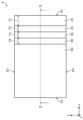
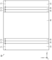
- FIG. 1 is a top view of a battery according to a first embodiment.
- FIG. 2 is a cross-sectional view of the battery according to the first embodiment.
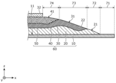
- FIG. 3 is a cross-sectional view showing another example of the structure of the end portion of the unit cell according to the first embodiment.
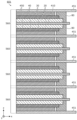
- FIG. 4 is a cross-sectional view of a battery according to a first modification of the first embodiment.
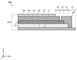
- FIG. 5 is a cross-sectional view of a battery according to Modification 2 of Embodiment 1.
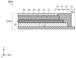
- FIG. 6 is a cross-sectional view of another battery according to the second modification of the first embodiment.
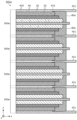
- FIG. 7 is a cross-sectional view of a battery according to Modification 3 of Embodiment 1. As shown in FIG. FIG. FIG.
- FIG. 8 is a cross-sectional view of another battery according to the third modification of the first embodiment.
- FIG. 9 is a top view of a battery according to the fourth modification of the first embodiment.
- FIG. 10 is a cross-sectional view of a battery according to Modification 4 of Embodiment 1.
- FIG. 11 is a cross-sectional view of another battery according to the fourth modification of the first embodiment.
- FIG. 12 is a cross-sectional view of a battery according to a fifth modification of the first embodiment.
- FIG. 13 is a cross-sectional view of another battery according to the fifth modification of the first embodiment.
- FIG. 14 is a cross-sectional view of still another battery according to the fifth modification of the first embodiment.
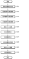
- FIG. 15 is a flowchart showing a method for manufacturing a battery according to the fifth modification of the first embodiment.
- FIG. 16 is a top view showing an example of a laminated electrode plate.
- FIG. 17 is a cross-sectional view of a battery according to the second embodiment.
- FIG. 18 is a cross-sectional view of another battery according to the second embodiment.
- FIG. 19 is a flowchart showing a method for manufacturing a battery according to the second embodiment.
- a short circuit is likely to occur due to contact between the end of the electrode active material layer and the counter electrode active material layer or the counter electrode current collector, or contact between the end of the counter electrode active material layer and the electrode active material layer or the electrode current collector.
- a terminal may be formed at the end of the battery in order to extract current.
- a terminal may be formed in a region not covered by the electrode active material layer at the end of the electrode current collector, but in this region, a short circuit is likely to occur due to contact between the electrode collector and the counter electrode active material layer and the counter electrode current collector. Furthermore, when a plurality of unit cells are stacked, the possibility of a short circuit at the end surface increases due to misalignment of the stacked unit cells. In addition, when the end of the active material layer is exposed, a short circuit is likely to occur due to the active material falling off.
- the present inventors have focused on the problem that the reliability of the battery is likely to decrease when a terminal is formed at the end of the unit cell, and have also focused on the fact that the decrease in the reliability of the battery can be suppressed by the manufacturing method of the battery.
- the battery according to the first aspect of the present disclosure comprises a unit cell having an electrode collector, an electrode active material layer disposed on the main surface of the electrode collector, an electrolyte layer disposed on the side of the electrode active material layer opposite the electrode collector, a counter electrode active material layer disposed on the side of the electrolyte layer opposite the electrode active material layer, and a counter electrode collector disposed on the side of the counter electrode active material layer opposite the electrolyte layer, and a first region that is not covered by the electrode active material layer is provided at an end of the main surface of the electrode collector in a first direction, which is a direction from the center toward the outer edge of the main surface of the electrode collector, a second region that is not covered by the electrolyte layer is provided at an end of the electrode active material layer in the first direction in a plan view relative to the main surface of the electrode collector, and a third region that is not covered by the counter electrode active material layer in the plan view is provided at an end of the electrolyte layer in the first direction.
- the second and third regions can increase the distance between the electrode collector and electrode active material layer and the counter electrode active material layer and counter electrode collector. As a result, short circuits caused by contact between electrodes of opposite polarity are less likely to occur. This can improve the reliability of the battery.
- the battery according to the second aspect of the present disclosure may be the battery according to the first aspect, in which the unit cell has two of each of the electrode active material layer, the electrolyte layer, the counter electrode active material layer, and the counter electrode current collector, the two electrode active material layers are disposed on both main surfaces of the electrode current collector, the two electrolyte layers are disposed on the opposite side of each of the two electrode active material layers from the electrode current collector, the two counter electrode active material layers are disposed on the opposite side of each of the two electrolyte layers from the electrode active material layer, the two counter electrode current collectors are disposed on the opposite side of each of the two counter electrode active material layers from the electrolyte layer, the first region is provided at the end of each of the two main surfaces of the electrode current collector in the first direction, the second region is provided at the end of each of the two electrode active material layers in the first direction, and the third region is provided at the end of each of the two electrolyte layers in the first direction.
- the distance between the electrode current collector and the electrode active material layer and the counter electrode active material layer and counter electrode current collector is increased on both main surface sides of the electrode current collector, making it less likely for a short circuit to occur and improving the reliability of the battery.
- a battery according to a third aspect of the present disclosure may be a battery according to the first aspect, in which a fourth region that is not covered by the counter electrode current collector in the plan view is provided at the end of the counter electrode active material layer in the first direction.
- the fourth region can further increase the distance between the electrode collector and the electrode active material layer and the counter electrode collector, making it even less likely that a short circuit will occur and improving the reliability of the battery.
- a battery according to a fourth aspect of the present disclosure is a battery according to the third aspect, in which the unit cell has two of each of the electrode active material layer, the electrolyte layer, the counter electrode active material layer, and the counter electrode current collector, the two electrode active material layers are disposed on both main surfaces of the electrode current collector, the two electrolyte layers are disposed on the opposite side of each of the two electrode active material layers from the electrode current collector, the two counter electrode active material layers are disposed on the opposite side of each of the two electrolyte layers from the electrode active material layer, and the two front The counter electrode current collector may be disposed on the opposite side of each of the two counter electrode active material layers from the electrolyte layer, and the first region may be provided at the end in the first direction of each of the main surfaces of the electrode current collector, the second region may be provided at the end in the first direction of each of the two electrode active material layers, the third region may be provided at the end in the first direction of each of the two electrolyte layers, and the fourth
- the distance between the electrode current collector and the electrode active material layer and the counter electrode active material layer and counter electrode current collector is increased on both main surface sides of the electrode current collector, making it less likely for a short circuit to occur and improving the reliability of the battery.
- a battery according to a fifth aspect of the present disclosure may be a battery according to any one of the first to fourth aspects, in which the electrode active material layer has an inclined surface in the second region that is inclined so as to approach the electrode current collector as it progresses in the first direction, and the electrolyte layer has an inclined surface in the third region that is inclined so as to approach the electrode current collector as it progresses in the first direction.
- a battery according to a sixth aspect of the present disclosure may be a battery according to the third or fourth aspect, in which the electrode active material layer has an inclined surface in the second region that is inclined so as to approach the electrode current collector as it progresses in the first direction, the electrolyte layer has an inclined surface in the third region that is inclined so as to approach the electrode current collector as it progresses in the first direction, and the counter electrode active material layer has an inclined surface in the fourth region that is inclined so as to approach the electrode current collector as it progresses in the first direction.
- a battery according to a seventh aspect of the present disclosure is a battery according to any one of the first to sixth aspects, and the electrode active material layer may be provided with a recess in which the electrolyte layer in the third region is recessed.
- This increases the bonding strength between the electrode active material layer and the electrolyte layer at the end of the unit cell in the first direction, making the materials of these layers less likely to fall off and reducing the likelihood of short circuits caused by contact between electrodes of opposite polarity.
- a battery according to an eighth aspect of the present disclosure may be a battery according to any one of the third, fourth, and sixth aspects, in which the electrode active material layer is provided with a recess in which the electrolyte layer in the third region is recessed, and the electrolyte layer is provided with a recess in which the counter electrode active material layer in the fourth region is recessed.
- the bonding strength between the electrode active material layer and the electrolyte layer and the bonding strength between the electrolyte layer and the counter electrode active material layer are increased, making the materials of these layers less likely to fall off and reducing the likelihood of short circuits caused by contact between electrodes of opposite polarity.
- a battery according to a ninth aspect of the present disclosure is a battery according to any one of the first to eighth aspects, and the unit cell may further have an insulating layer covering at least a portion of the first region, at least a portion of the second region, and at least a portion of the third region.
- a battery according to a tenth aspect of the present disclosure is a battery according to any one of the third, fourth, sixth, and eighth aspects, and the unit cell may further have an insulating layer covering at least a portion of the first region, at least a portion of the second region, and at least a portion of the third region.
- the electrode current collector and electrode active material layer are covered in the first and second regions by the insulating layer that extends to the third region, greatly reducing the possibility of a short circuit caused by contact between the electrode current collector and electrode active material layer and the counter electrode current collector and counter electrode active material layer. This improves the reliability of the battery.
- a battery according to an eleventh aspect of the present disclosure may be a battery according to the tenth aspect, in which the insulating layer further covers at least a portion of the fourth region.
- a battery according to a twelfth aspect of the present disclosure is a battery according to any one of the ninth to eleventh aspects, and a part of the end of the counter electrode collector in the first direction may protrude in the first direction beyond the insulating layer in the plan view.
- a battery according to a thirteenth aspect of the present disclosure may be a battery according to any one of the first to twelfth aspects, in which the side surfaces of the electrode collector, the electrode active material layer, the electrolyte layer, and the counter electrode active material layer are flush with each other at the end of the unit cell in a second direction that is from the center toward the outer edge of the main surface of the electrode collector and is different from the first direction.
- a battery according to a fourteenth aspect of the present disclosure may be a battery according to any one of the first to twelfth aspects, in which the side surfaces of the electrode collector, the electrode active material layer, the electrolyte layer, the counter electrode active material layer, and the counter electrode collector are flush with each other at the end of the unit cell in a second direction that is from the center to the outer edge of the main surface of the electrode collector and is different from the first direction.
- a battery according to a fifteenth aspect of the present disclosure may be a battery according to any one of the first to thirteenth aspects, and may include a plurality of the unit cells, and the plurality of unit cells may be stacked.
- the method for manufacturing a battery according to the sixteenth aspect of the present disclosure includes stacking a plurality of laminates each having an electrode collector, an electrode active material layer arranged on the main surface of the electrode collector, an electrolyte layer arranged on the side of the electrode active material layer opposite the electrode collector, and a counter electrode active material layer arranged on the side of the electrolyte layer opposite the electrode active material layer, together with a plurality of counter electrode collectors, such that the counter electrode collector is stacked on the side of the counter electrode active material layer opposite the electrolyte layer, and then pressing the laminate together after stacking.
- the method for manufacturing a battery according to the seventeenth aspect of the present disclosure may be the method for manufacturing a battery according to the sixteenth aspect, in which at least one of the multiple laminates has only the electrode current collector as a current collector.
- the manufacturing method of a battery according to the 18th aspect of the present disclosure may be the manufacturing method of a battery according to the 16th or 17th aspect, in which each of the multiple laminates has two of each of the electrode active material layers, the electrolyte layers, and the counter electrode active material layers, the two electrode active material layers are disposed on both main surfaces of the electrode collector, the two electrolyte layers are disposed on the side opposite the electrode collector from each of the two electrode active material layers, and the two counter electrode active material layers are disposed on the side opposite the electrode active material layers from each of the two electrolyte layers.
- a manufacturing method of a battery according to a 19th aspect of the present disclosure may be a manufacturing method of a battery according to any one of the 16th to 18th aspects, in which a first region that is not covered by the electrode active material layer is provided at an end of the main surface of the electrode collector in a first direction, which is a direction from the center toward the outer edge of the main surface of the electrode collector, a second region that is not covered by the electrolyte layer is provided at the end of the electrode active material layer in the first direction in a plan view relative to the main surface of the electrode collector, and a third region that is not covered by the counter electrode active material layer is provided at the end of the electrolyte layer in the first direction in the plan view.
- the second and third regions can increase the distance between the electrode collector and electrode active material layer and the counter electrode active material layer and counter electrode collector. As a result, short circuits caused by contact between electrodes of opposite polarity are less likely to occur. This can improve the reliability of the battery.
- the method for manufacturing a battery according to the 20th aspect of the present disclosure may be the method for manufacturing a battery according to the 19th aspect, in which the counter electrode current collector has a protrusion in which a part of the end in the first direction protrudes in the first direction.
- each figure is a schematic diagram and is not necessarily an exact illustration. Therefore, for example, the scales of each figure do not necessarily match.
- the same reference numerals are used for substantially the same configuration, and duplicate explanations are omitted or simplified.
- the x-axis, y-axis, and z-axis indicate the three axes of a three-dimensional Cartesian coordinate system.
- the x-axis and y-axis are parallel to the main surface of the electrode current collector, and the z-axis is perpendicular to the main surface of the electrode current collector.
- the x-axis and y-axis are parallel to the first side of the rectangle and the second side perpendicular to the first side, respectively.
- the z-axis is the stacking direction of the multiple unit cells included in the battery.
- the "stacking direction” coincides with the normal direction of the main surfaces of the current collector and the active material layer.
- plane view refers to the view from a direction perpendicular to the main surface of the electrode current collector, unless otherwise specified.
- the terms “above” and “below” do not refer to the upward (vertically upward) and downward (vertically downward) directions in an absolute spatial sense, but are used as terms defined by a relative positional relationship based on the stacking order in a stacked configuration. Furthermore, the terms “above” and “below” are applied not only to cases where two components are arranged with a gap between them and another component exists between the two components, but also to cases where two components are arranged in close contact with each other and are in contact. In the following explanation, the negative side of the z axis is referred to as “below” or “lower side”, and the positive side of the z axis is referred to as “above” or "upper side”.
- protruding means protruding outward from the center of the unit cell in a cross-sectional view perpendicular to the main surface of the electrode current collector.
- element A protrudes from element B means that the tip of element A protrudes further from the tip of element B in the protruding direction, i.e., the tip of element A is farther from the center of the unit cell than the tip of element B.
- the "protruding direction” is considered to be a direction parallel to the main surface of the electrode current collector.
- the "protruding portion of element A” means a part of element A that protrudes further from the tip of element B in the protruding direction.
- element B may be a part other than the protruding portion of element A.
- the element is, for example, an active material layer, a solid electrolyte layer, an insulating layer, a current collector, etc.
- ordinal numbers such as “first” and “second” do not refer to the number or order of components, unless otherwise specified, but are used for the purpose of avoiding confusion between and distinguishing between components of the same type.
- FIG. 1 is a top view of battery 1 according to this embodiment.
- FIG. 2 is a cross-sectional view of battery 1 according to this embodiment.
- FIG. 1 shows the planar shape of battery 1 as viewed from the positive side of the z-axis.
- FIG. 2 is a cross-sectional view taken at the position indicated by line II-II in FIG. 1.
- the battery 1 includes a unit cell 60 having an electrode current collector 10, an electrode active material layer 20, a solid electrolyte layer 30, a counter electrode active material layer 40, and a counter electrode current collector 50.
- the electrode current collector 10, the electrode active material layer 20, the solid electrolyte layer 30, the counter electrode active material layer 40, and the counter electrode current collector 50 are stacked in this order along the z-axis.
- the battery 1 is formed from one unit cell 60.
- the battery 1 is, for example, an all-solid-state battery.
- the unit cell 60 has side faces 61 and 62 facing away from each other, and side faces 63 and 64 facing away from each other.
- Side face 61 is the side face of the unit cell 60 facing the direction moving toward the positive side along the x-axis.
- Side face 62 is the side face of the unit cell 60 facing the direction moving toward the negative side along the x-axis.
- Side face 63 is the side face of the unit cell 60 facing the direction moving toward the positive side along the y-axis.
- Side face 64 is the side face of the unit cell 60 facing the direction moving toward the negative side along the y-axis.
- the direction along the x-axis toward the positive side is referred to as the "x-axis positive direction”.
- the direction along the x-axis toward the negative side is referred to as the "x-axis negative direction”.
- the direction along the y-axis toward the positive side is referred to as the "y-axis positive direction”.
- the direction along the y-axis toward the negative side is referred to as the "y-axis negative direction”.
- the x-axis positive direction and the x-axis negative direction are mutually orthogonal to the y-axis positive direction and the y-axis negative direction.
- the x-axis positive direction and the x-axis negative direction are mutually opposite directions
- the y-axis positive direction and the y-axis negative direction are mutually opposite directions.
- the x-axis positive direction is an example of a first direction that is a direction from the center of the main surface 11 of the electrode collector 10 toward the outer edge.
- the x-axis negative direction is an example of a second direction that is a direction from the center of the main surface 11 of the electrode collector 10 toward the outer edge and is different from the first direction.
- the second direction may be the positive y-axis direction or the negative y-axis direction.
- the first region 71, the second region 72, the third region 73 and the fourth region 74 are provided at the end of the side surface 61 of the unit cell 60, but these regions may be provided at the end of the side surface 62, the side surface 63 or the side surface 64 of the unit cell 60. Details of the first region 71, the second region 72, the third region 73 and the fourth region 74 will be described later.
- the planar shape of the battery 1 and the unit cell 60 is rectangular as shown in FIG. 1.
- the general shape of the battery 1 and the unit cell 60 is a flattened rectangular parallelepiped.
- "flat" means that the thickness is shorter than each side or the maximum width of the main surface.
- Each side or the maximum width of the main surface of the battery 1 and the unit cell 60 is, for example, 10 mm or more and 500 mm or less.
- the planar shape of the battery 1 and the unit cell 60 may be a polygon such as a square, hexagon, or octagon, or may be a circle or an ellipse. In the drawings related to this specification, the thickness of each layer is exaggerated to make the layer structure of the unit cell easier to understand.
- the lengths of the first region 71, the second region 72, the third region 73, and the fourth region 74 in the x-axis positive direction are exaggerated to make the structure of the unit cell in the first region 71, the second region 72, the third region 73, and the fourth region 74 easier to understand.
- the side surfaces 62, 63, and 64 of the unit cell 60 are composed of the side surfaces of the electrode collector 10, the electrode active material layer 20, the solid electrolyte layer 30, the counter electrode active material layer 40, and the counter electrode collector 50, and at least a part of them may be flat planes.
- the side surfaces 62, 63, and 64 are flat planes, at least the side surfaces of the electrode collector 10, the electrode active material layer 20, the solid electrolyte layer 30, and the counter electrode active material layer 40 are in a state without any steps on this plane and are located on the same flat plane.
- the side surfaces of the electrode collector 10, the electrode active material layer 20, the solid electrolyte layer 30, and the counter electrode active material layer 40 are flush with each other. Furthermore, at the ends of the unit cell 60 in the negative x-axis direction, the positive y-axis direction, and the negative y-axis direction, the side surfaces of the electrode collector 10, the electrode active material layer 20, the solid electrolyte layer 30, the counter electrode active material layer 40, and the counter electrode collector 50 may be flush.
- Side surfaces 62, 63, and 64 are, for example, cut surfaces. Specifically, side surfaces 62, 63, and 64 are surfaces formed by cutting with a blade such as a cutter, and are, for example, surfaces having cut marks such as fine grooves. By being cut surfaces, the side surfaces of each layer of unit cell 60 can be easily made flush. The cut marks may be smoothed by polishing, for example. The shape of the cut surfaces is not limited.
- the sides 61, 62, 63, and 64 each form one side of the rectangle of the unit cell 60 in plan view.
- the unit cell 60 has one each of the electrode collector 10, electrode active material layer 20, solid electrolyte layer 30, counter electrode active material layer 40, and counter electrode collector 50.
- the electrode collector 10, electrode active material layer 20, solid electrolyte layer 30, counter electrode active material layer 40, and counter electrode collector 50 overlap each other.
- the electrode current collector 10 is in contact with the electrode active material layer 20 on one of its main surfaces 11.
- the thickness of the electrode current collector 10 is, for example, 5 ⁇ m or more and 100 ⁇ m or less. In this specification, the thickness of the current collector and each layer is the length in the stacking direction, and unless otherwise specified, is the average value of the overall thickness.
- a known material can be used as the material for the electrode current collector 10.
- a foil, plate or mesh made of copper, aluminum, nickel, iron, stainless steel, platinum or gold, or an alloy of two or more of these, can be used for the electrode current collector 10.
- the electrode current collector 10 may also include a connection layer that is a layer containing a conductive material and is provided in the portion that contacts the electrode active material layer 20.
- the counter electrode current collector 50 is disposed on the side of the counter electrode active material layer 40 opposite the solid electrolyte layer 30 side.
- the counter electrode current collector 50 is in contact with the upper surface of the counter electrode active material layer 40.
- the counter electrode current collector 50 faces the electrode current collector 10 via the electrode active material layer 20, the solid electrolyte layer 30, and the counter electrode active material layer 40.
- the thickness of the counter electrode current collector 50 is, for example, 5 ⁇ m or more and 100 ⁇ m or less.
- a known material can be used as the material for the counter electrode current collector 50.
- a foil, plate, or mesh made of copper, aluminum, nickel, iron, stainless steel, platinum, or gold, or an alloy of two or more of these, can be used for the counter electrode current collector 50.
- the counter electrode current collector 50 may also include a connection layer that is a layer containing a conductive material and is provided in the portion that contacts the counter electrode active material layer 40.
- the electrode active material layer 20 is disposed on one of the main surfaces 11 of the electrode collector 10.
- the surface of the electrode active material layer 20 opposite the electrode collector 10 is in contact with the solid electrolyte layer 30.
- the electrode active material layer 20 and the counter electrode active material layer 40 face each other with the solid electrolyte layer 30 in between.
- the area of the electrode active material layer 20 is larger than the area of the counter electrode active material layer 40.
- the thickness of the electrode active material layer 20 is, for example, 5 ⁇ m or more and 300 ⁇ m or less. The materials used for the electrode active material layer 20 will be described later.
- the solid electrolyte layer 30 is disposed on the side of the electrode active material layer 20 opposite the electrode collector 10 side.
- the solid electrolyte layer 30 is located between the electrode active material layer 20 and the counter electrode active material layer 40, and is in contact with the electrode active material layer 20 and the counter electrode active material layer 40.
- the thickness of the solid electrolyte layer 30 is, for example, 5 ⁇ m or more and 150 ⁇ m or less. The materials used for the solid electrolyte layer 30 will be described later.
- the counter electrode active material layer 40 is disposed on the side of the solid electrolyte layer 30 opposite the electrode active material layer 20.
- the counter electrode active material layer 40 is laminated on the solid electrolyte layer 30 and faces the electrode active material layer 20.
- the thickness of the counter electrode active material layer 40 is, for example, 5 ⁇ m or more and 300 ⁇ m or less. The materials used for the counter electrode active material layer 40 will be described later.
- the solid electrolyte layer 30 is an example of an electrolyte layer containing an electrolyte material.
- the solid electrolyte layer 30 contains at least a solid electrolyte as an electrolyte material, and may contain a binder material as necessary.
- the solid electrolyte layer 30 may contain a solid electrolyte having lithium ion conductivity.
- the electrolyte material contained in the solid electrolyte layer 30 is all solid electrolytes, for example, except for unavoidable impurities. Note that the electrolyte material used in the solid electrolyte layer 30 may further contain a nonaqueous electrolyte solution, a gel electrolyte solution, or an ionic liquid, so long as it contains a solid electrolyte as a main component. Below, a case will be described in which all the electrolyte materials contained in the solid electrolyte layer 30 are solid electrolytes.
- solid electrolyte known materials such as lithium ion conductors, sodium ion conductors, or magnesium ion conductors can be used.
- a solid electrolyte material such as a sulfide solid electrolyte, a halide solid electrolyte, an oxide solid electrolyte, a polymer solid electrolyte, or a complex hydride solid electrolyte can be used.
- the sulfide solid electrolyte in the case of a material capable of conducting lithium ions, for example, a composite of lithium sulfide (Li 2 S) and diphosphorus pentasulfide (P 2 S 5 ) is used.
- a sulfide such as Li 2 S-SiS 2 , Li 2 S-B 2 S 3 or Li 2 S-GeS 2 may be used, and a sulfide in which at least one of Li 3 N, LiCl, LiBr, Li 3 PO 4 and Li 4 SiO 4 is added as an additive to the above sulfide may be used.
- the oxide solid electrolyte in the case of a material capable of conducting lithium ions, for example, Li7La3Zr2O12 ( LLZ ) , Li1.3Al0.3Ti1.7 ( PO4 ) 3 ( LATP ) or (La,Li) TiO3 (LLTO) is used.
- a material capable of conducting lithium ions for example, Li7La3Zr2O12 ( LLZ ) , Li1.3Al0.3Ti1.7 ( PO4 ) 3 ( LATP ) or (La,Li) TiO3 (LLTO) is used.
- binder material for example, elastomers such as styrene-based elastomers are used, and organic compounds such as polyvinylidene fluoride, acrylic resins, or cellulose resins may also be used.
- one of the electrode active material layer 20 and the counter electrode active material layer 40 is a positive electrode active material layer, and the other is a negative electrode active material layer.
- the positive electrode active material layer contains at least a positive electrode active material, and may contain at least one of an electrolyte material such as a solid electrolyte, a conductive additive, and a binder material, as necessary.
- an electrolyte material such as a solid electrolyte, a conductive additive, and a binder material, as necessary.
- the positive electrode active material known materials capable of absorbing and releasing (inserting and desorbing, or dissolving and depositing) lithium ions, sodium ions, magnesium ions, etc. can be used.
- the positive electrode active material in the case of a material capable of extracting and inserting lithium ions, for example, transition metal oxides, transition metal fluorides, polyanion materials, fluorinated polyanion materials, transition metal sulfides, transition metal oxysulfides, transition metal oxynitrides, sulfur, lithium-containing compounds thereof, etc. can be mentioned.
- the lithium-containing transition metal oxides Li(NiCoAl)O 2 , Li(NiCoMn)O 2 , LiCoO 2 , etc. can be mentioned.
- Li(NiCoAl)O 2 means that Ni, Co, and Al are contained in any ratio.
- Li(NiCoMn)O 2 means that Ni, Co, and Mn are contained in any ratio.
- the solid electrolyte materials exemplified above can be used.
- the conductive material used in the conductive assistant for example, acetylene black, carbon black, graphite, carbon fiber, vapor-grown carbon, or conductive carbon such as carbon nanotubes can be used.
- the binder material the binder materials exemplified above can be used.
- the negative electrode active material layer contains at least a negative electrode active material, and may contain at least one of an electrolyte material such as a solid electrolyte, a conductive additive, and a binder material, as necessary.
- an electrolyte material such as a solid electrolyte, a conductive additive, and a binder material, as necessary.
- a known material capable of absorbing and releasing (inserting and desorbing, or dissolving and precipitating) lithium ions, sodium ions, magnesium ions, etc. can be used as the negative electrode active material.
- a material capable of extracting and inserting lithium ions for example, carbon materials such as natural graphite, artificial graphite, graphite carbon fiber, or resin-baked carbon, metallic lithium, lithium alloys, silicon (Si), tin (Sn), silicon compounds, tin compounds, or oxides of lithium and transition metal elements can be used as the negative electrode active material.
- the solid electrolyte materials exemplified above can be used.
- the conductive assistant the conductive materials exemplified above can be used.
- the binder material the binder materials exemplified above can be used.
- a first region 71, a second region 72, a third region 73, and a fourth region 74 that are not covered by the upper layer are provided at the end in the positive x-axis direction (the end along the side surface 61 in the example shown in Figure 1).
- a first region 71 that is not covered by the electrode active material layer 20 is provided at the end of the main surface 11 of the electrode collector 10 in the positive x-axis direction.
- the first region 71 is not in contact with the electrode active material layer 20, the solid electrolyte layer 30, the counter electrode active material layer 40, and the counter electrode current collector 50.
- a second region 72 that is not covered by the solid electrolyte layer 30 in a plan view is provided at the end of the electrode active material layer 20 in the positive x-axis direction.
- the second region 72 is not in contact with the solid electrolyte layer 30, the counter electrode active material layer 40, and the counter electrode current collector 50.
- a third region 73 that is not covered by the counter electrode active material layer 40 in a plan view is provided at the end of the solid electrolyte layer 30 in the positive x-axis direction.
- the third region 73 is not in contact with the counter electrode active material layer 40 and the counter electrode current collector 50.
- the third region 73 is farther from the electrode collector 10 than the second region 72.
- a fourth region 74 that is not covered by the counter electrode current collector 50 in a plan view is provided at the end of the counter electrode active material layer 40 in the positive x-axis direction. The fourth region 74 is farther from the electrode current collector 10 than the third region 73.
- the second region 72, the third region 73, and the fourth region 74 increase the distance between the electrode collector 10 and the electrode active material layer 20 and the end of the counter electrode active material layer 40, and the distance between the electrode collector 10 and the electrode active material layer 20 and the end of the counter electrode collector 50.
- short circuits caused by contact between electrodes of opposite polarity are less likely to occur. Therefore, the reliability of the battery 1 can be improved.
- the structure does not include the first region 71 to the fourth region 74, short circuits are likely to occur.
- a region corresponding to the first region 71 is provided on the electrode collector and a region corresponding to the third region 73 is provided on the solid electrolyte layer, but since regions corresponding to the second region 72 and the fourth region 74 are not provided, the electrode collector and the counter electrode collector are likely to come into contact with each other.
- an insulating layer is provided on the main surface of the counter electrode collector facing the electrode collector to prevent short circuits.
- the positional precision of the insulating layer is improved, it is difficult to obtain a sufficient short circuit prevention effect, and it is also difficult to improve the manufacturing efficiency of the battery.
- the first region 71, the second region 72, the third region 73, and the fourth region 74 are provided along the side surface 61 in a plan view.
- the first region 71, the second region 72, the third region 73, and the fourth region 74 are elongated in a plan view, and in the example shown in FIG. 1, the direction perpendicular to the positive x-axis direction (the y-axis direction) is the longitudinal direction.
- the fourth region 74, the third region 73, the second region 72, and the first region 71 are arranged in this order along the positive x-axis direction in a plan view.
- the length of the first region 71 is, for example, 1 mm or more and 20 mm or less. This allows the energy density of the battery 1 to be increased while ensuring an area in which a terminal can be easily formed on the electrode collector 10.
- the length of the second region 72, the third region 73, and the fourth region 74 is, for example, 0.1 mm or more and 5 mm or less. This allows the energy density of the battery 1 to be increased while increasing the above-mentioned distance.
- the length of the second region 72, the third region 73, and the fourth region 74 may be, for example, 0.5 mm or more and 2 mm or less.
- the lengths of the first region 71, the second region 72, the third region 73, and the fourth region 74 may be the same as each other, or at least one of them may be different. Also, the length of the first region 71 may be longer than the lengths of the second region 72, the third region 73, and the fourth region 74.
- the lengths of the first region 71, the second region 72, the third region 73, and the fourth region 74 are lengths in the positive x-axis direction in plan view.
- the length of the first region 71 is also the distance between the outer edge of the electrode current collector 10 and the outer edge of the electrode active material layer 20 in the positive x-axis direction in plan view.
- the length of the second region 72 is also the distance in plan view between the outer edge of the electrode active material layer 20 and the outer edge of the solid electrolyte layer 30 in the positive x-axis direction.
- the length of the third region 73 is also the distance in plan view between the outer edge of the solid electrolyte layer 30 and the outer edge of the counter electrode active material layer 40 in the positive x-axis direction.
- the length of the fourth region 74 is also the distance in plan view between the outer edge of the counter electrode active material layer 40 and the outer edge of the counter electrode current collector 50 in the positive x-axis direction.
- the electrode active material layer 20 may be a negative electrode active material layer
- the counter electrode active material layer 40 may be a positive electrode active material layer.
- the fourth region 74 in the counter electrode active material layer 40 that is not covered by the counter electrode current collector 50 becomes a region that is difficult to function as a positive electrode.
- the electrode active material layer 20 becomes relatively larger than the counter electrode active material layer 40. Therefore, metal ions are easily taken up into the electrode active material layer 20, which is a negative electrode active material layer, and the precipitation of metal derived from the metal ions is suppressed, and the reliability of the battery 1 can be further improved.
- the electrode collector 10, electrode active material layer 20, solid electrolyte layer 30, counter electrode active material layer 40, and counter electrode collector 50 form a stepped structure at the end of the unit cell 60 in the positive x-axis direction, but this is not limited to this.
- Figure 3 is a cross-sectional view showing another example of the structure of the end of the unit cell 60.
- the electrode active material layer 20 has an inclined surface 21 in the second region 72 that is inclined so as to approach the electrode current collector 10 as it progresses in the positive x-axis direction.
- the entire second region 72 is, for example, the region in which the inclined surface 21 is formed.
- the solid electrolyte layer 30 has an inclined surface 31 in the third region 73 that is inclined so as to approach the electrode current collector 10 as it progresses in the positive x-axis direction.
- the entire third region 73 is, for example, the region in which the inclined surface 31 is formed.
- the counter electrode active material layer 40 has an inclined surface 41 in the fourth region 74 that is inclined so as to approach the electrode current collector 10 as it progresses in the positive x-axis direction.
- the entire fourth region 74 is, for example, the region in which the inclined surface 41 is formed.
- the inclined surface 21 and the inclined surface 31 are connected, and the inclined surface 31 and the inclined surface 41 are connected.
- inclined surfaces 21, 31, and 41 form one continuous inclined surface.
- These inclined surface shapes can be formed, for example, by performing a high-pressure press process such as a roll press on a portion including the end of a laminate in which the electrode active material layer 20, the solid electrolyte layer 30, and the counter electrode active material layer 40 are stacked on the electrode current collector 10 so that the end is stepped.
- a high-pressure press process such as a roll press
- the angle that each of the inclined surfaces 21, 31, and 41 makes with respect to the main surface 11 is, for example, less than 45 degrees. This makes it even more difficult for the material of the layer to fall off.
- the angle that each of the inclined surfaces 21, 31, and 41 makes with respect to the main surface 11 may be 30 degrees or less, or 10 degrees or less. Also, the angle that each of the inclined surfaces 21, 31, and 41 makes with respect to the main surface 11 is, for example, 1 degree or more.
- the electrode active material layer 20 has a recess 22 in the third region 73 into which the solid electrolyte layer 30 is recessed.
- the solid electrolyte layer 30 has a recess 32 in the fourth region 74 into which the counter electrode active material layer 40 is recessed.
- This recessed shape can be formed, for example, by performing a high-pressure press process such as a roll press on a portion including the end of the stack in which the electrode active material layer 20, the solid electrolyte layer 30, and the counter electrode active material layer 40 are stacked on the electrode current collector 10 so that the end is stepped.
- a high-pressure press process such as a roll press
- each of the recesses 22 and 32 is, for example, 1 ⁇ m or more and 10 ⁇ m or less.
- the surface of the electrode active material layer 20 facing the solid electrolyte layer 30 below the inclined surface 41 (i.e., the position overlapping with the inclined surface 41 in a plan view) has a portion that inclines away from the electrode current collector 10 as it progresses in the positive x-axis direction. Therefore, at the position of the outer edge of the counter electrode active material layer 40 in the positive x-axis direction in a plan view, the thickness of the electrode active material layer 20 is greater than the thickness of the electrode active material layer 20 on the inside of that position.
- the structure of the ends of the electrode active material layer 20, solid electrolyte layer 30, and counter electrode active material layer 40 in the positive x-axis direction shown in FIG. 3 may be included in the batteries according to the embodiments and modifications described below.
- Fig. 4 is a cross-sectional view of a battery 101 according to this modification.
- the battery 101 includes a unit cell 160 and is formed from one unit cell 160.
- the unit cell 160 differs from the unit cell 60 according to the first embodiment in that the unit cell 160 has two of each of the electrode active material layer 20, the solid electrolyte layer 30, the counter electrode active material layer 40, and the counter electrode current collector 50.
- two electrode active material layers 20 are disposed on both main surfaces 11 and 12 of the electrode collector 10.
- Two solid electrolyte layers 30 are disposed on the side of each of the two electrode active material layers 20 opposite the electrode collector 10.
- Two counter electrode active material layers 40 are disposed on the side of each of the two solid electrolyte layers 30 opposite the electrode active material layer 20.
- Two counter electrode collectors 50 are disposed on the side of each of the two counter electrode active material layers 40 opposite the solid electrolyte layer 30.
- a first region 71 that is not covered by either of the two electrode active material layers 20 is provided at the end in the positive x-axis direction of each of the main surfaces 11 and 12 of the electrode current collector 10.
- a second region 72 that is not covered by either of the two solid electrolyte layers 30 is provided at the end in the positive x-axis direction of each of the two electrode active material layers 20.
- a third region 73 that is not covered by either of the two counter electrode active material layers 40 is provided at the end in the positive x-axis direction of each of the two solid electrolyte layers 30.
- a fourth region 74 that is not covered by either of the two counter electrode current collectors 50 is provided at the end in the positive x-axis direction of each of the two counter electrode active material layers 40.
- the unit cell 160 in the unit cell 160, a structure similar to the laminated structure of the electrode active material layer 20, solid electrolyte layer 30, counter electrode active material layer 40, and counter electrode collector 50 formed on the main surface 11 of the electrode collector 10 of the unit cell 60 is also formed upside down on the main surface 12 facing away from the main surface 11 of the electrode collector 10. Therefore, the unit cell 160 has a laminated structure that is symmetrical with respect to the electrode collector 10.
- the first region 71, the second region 72, the third region 73, and the fourth region 74 are provided on both sides of the electrode collector 10 in the stacking direction, the distance between the electrode collector 10 and the electrode active material layer 20 and the end of the counter electrode active material layer 40, and the distance between the electrode collector 10 and the electrode active material layer 20 and the end of the counter electrode collector 50 are increased, thereby ensuring reliability.
- the electrode active material layer 20 the solid electrolyte layer 30, the counter electrode active material layer 40, and the counter electrode collector 50 is formed on both main surfaces 11 and 12 of the electrode collector 10
- the stress generated on both sides of the electrode collector 10 in the stacking direction is less likely to differ, and warping of the unit cell 160 can be suppressed.
- Fig. 5 is a cross-sectional view of a battery 201 according to this modification.
- the battery 201 includes a unit cell 260 and is formed from one unit cell 260.
- the unit cell 260 differs from the unit cell 60 of the first embodiment in that it further includes an insulating layer 80.
- the insulating layer 80 covers a part of the first region 71 on the second region 72 side, the entire second region 72, and a part of the third region 73 on the second region 72 side.
- the electrode collector 10 and the electrode active material layer 20 are covered by the insulating layer 80 extending to the third region 73 in the first region 71 and the second region 72, and the possibility that the electrode collector 10 and the electrode active material layer 20 will come into contact with the counter electrode collector 50 and the counter electrode active material layer 40 can be significantly reduced. This can improve the reliability of the battery 201.
- the insulating layer 80 does not cover a part of the first region 71 or a part of the third region 73.
- a gap is provided between the counter electrode active material layer 40 and the insulating layer 80.
- the electrode current collector 10 protrudes from the end face of the insulating layer 80 in the positive x-axis direction.
- the insulating layer 80 is in contact with a part of the first region 71 on the second region 72 side, the entire second region 72, and a part of the third region 73 on the second region 72 side.
- the insulating layer 80 is also in contact with the end faces of the electrode active material layer 20 and the solid electrolyte layer 30 in the positive x-axis direction.
- the length of the portion where the insulating layer 80 and the first region 71 are in contact is, for example, 100 ⁇ m or more. This reduces the possibility of exposure of the electrode collector 10 and the electrode active material layer 20, thereby reducing the possibility of the electrode collector 10 and the electrode active material layer 20 coming into contact with the counter electrode collector 50 and the counter electrode active material layer 40, thereby improving the reliability of the battery 201.
- the length of the portion where the insulating layer 80 and the first region 71 are in contact is the length in the positive x-axis direction in a plan view, and is also the distance in a plan view between the outer edge of the electrode active material layer 20 and the outer edge of the insulating layer 80 in the positive x-axis direction.
- the height of the insulating layer 80 from the main surface 11 is equal to or less than the distance from the main surface 11 to the main surface of the counter electrode current collector 50 on the electrode current collector 10 side. This allows the space above the insulating layer 80 to be used effectively when forming a terminal on the counter electrode current collector 50. Also, when the batteries 201 are stacked for use, they can be easily stacked.
- the insulating layer 80 only needs to cover at least a portion of the first region 71, at least a portion of the second region 72, and at least a portion of the third region 73.
- the insulating layer 80 may cover the entire area of at least one of the first region 71 and the third region 73 in the positive x-axis direction, or may not cover a portion of the second region 72.
- the insulating layer 80 may cover the entire area of the first region 71, the second region 72, and the third region 73 in the longitudinal direction (y-axis direction) of the first region 71, the second region 72, and the third region 73 in a plan view, or may cover only a portion of them.
- the insulating layer 80 has, for example, electronic insulation and ionic insulation.
- an insulating tape or an insulating resin is used for the insulating layer 80.
- resins used for the insulating tape and the insulating resin include silicone resin, epoxy resin, acrylic resin, and polyimide resin.
- the resin may be a thermosetting resin or an ultraviolet curing resin.
- the insulating layer 80 may also contain a solid electrolyte.
- the solid electrolyte material exemplified above may be used as the solid electrolyte.
- the same material as the solid electrolyte material used for the solid electrolyte layer 30 may be used as the solid electrolyte.
- FIG. 6 is a cross-sectional view of another battery 201a according to this modified example.
- Battery 201a includes unit cell 260a and is formed from one unit cell 260a.
- Unit cell 260a has a configuration in which insulating layer 80 of unit cell 260 is changed to insulating layer 80a. In addition to the area covered by insulating layer 80, insulating layer 80a further covers fourth area 74.
- the insulating layer 80a covers a part of the first region 71 on the second region 72 side, the entire second region 72, the entire third region 73, and a part of the fourth region 74 on the third region 73 side. This makes it difficult for the solid electrolyte layer 30 to fall off, and even if the solid electrolyte layer 30 falls off, exposure of the electrode active material layer 20 can be avoided, making it difficult for a short circuit to occur due to contact between the counter electrode collector 50 and the counter electrode active material layer 40 and the electrode collector 10 and the electrode active material layer 20.
- the insulating layer 80a does not cover a part of the first region 71 or a part of the fourth region 74.
- a gap is provided between the counter electrode collector 50 and the insulating layer 80a.
- the electrode collector 10 protrudes in the positive x-axis direction beyond the end face of the insulating layer 80a in the positive x-axis direction.
- the insulating layer 80a is in contact with the end faces of the electrode active material layer 20, the solid electrolyte layer 30, and the counter electrode active material layer 40 in the positive x-axis direction.
- the insulating layer 80a only needs to cover at least a part of the first region 71, at least a part of the second region 72, at least a part of the third region 73, and at least a part of the fourth region 74.
- the insulating layer 80a may cover the entire area of at least one of the first region 71 and the fourth region 74 in the positive x-axis direction, and may not cover at least one of a part of the second region 72 and a part of the third region 73.
- the insulating layer 80a may cover the entire area of the first region 71, the second region 72, the third region 73, and the fourth region 74 in the longitudinal direction (y-axis direction) of the first region 71, the second region 72, the third region 73, and the fourth region 74 in a plan view, or may cover only a part of them.
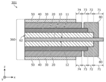
- FIG. 7 is a cross-sectional view of a battery 301 according to this modified example.
- Figure 8 is a cross-sectional view of another battery 301a according to this modified example.
- the battery 301 includes a unit cell 360 and is formed from one unit cell 360.
- the unit cell 360 differs from the unit cell 160 according to the first modification in that it further includes two insulating layers 80.
- One of the two insulating layers 80 is disposed on the main surface 11 side of the electrode collector 10 and covers at least a portion of the first region 71, at least a portion of the second region 72, and at least a portion of the third region 73.
- the other of the two insulating layers 80 is disposed on the main surface 12 side of the electrode collector 10 and covers at least a portion of the first region 71, at least a portion of the second region 72, and at least a portion of the third region 73.
- the battery 301a includes a unit cell 360a and is formed from one unit cell 360a.
- the unit cell 360a differs from the unit cell 160 according to the first modification in that it further includes two insulating layers 80a.
- One of the two insulating layers 80a is disposed on the main surface 11 side of the electrode collector 10 and covers at least a part of the first region 71, at least a part of the second region 72, at least a part of the third region 73, and at least a part of the fourth region 74.
- the other of the two insulating layers 80a is disposed on the main surface 12 side of the electrode collector 10 and covers at least a part of the first region 71, at least a part of the second region 72, at least a part of the third region 73, and at least a part of the fourth region 74.
- Fig. 9 is a top view of a battery 401 according to this modification.
- Fig. 10 is a cross-sectional view of the battery 401 according to this modification.
- Fig. 9 shows the shape of the battery 401 in plan view when viewed from the z-axis positive side.
- Fig. 10 is a cross-sectional view taken at the position indicated by line X-X in Fig. 9.
- the outlines of the electrode active material layer 20 and the solid electrolyte layer 30 when viewed through the insulating layer 80 are indicated by dashed lines.
- the battery 401 includes a unit cell 460 and is formed from one unit cell 460.
- the unit cell 460 differs from the unit cell 260 of Modification Example 2 in that it has an electrode current collector 410 and a counter electrode current collector 450 instead of the electrode current collector 10 and the counter electrode current collector 50.
- the electrode collector 410 has a protrusion 411, which is a portion of the end of the electrode collector 410 in the x-axis positive direction that protrudes further in the x-axis positive direction than other portions.
- the electrode collector 410 has a shape in which a rectangular tab-shaped protrusion 411 is added to the electrode collector 10 having a rectangular shape in plan view described above.
- the protrusion 411 functions, for example, as a lead on which a terminal is formed. Another lead material may be joined to the protrusion 411.
- the first region 71 is also provided inside the protrusion 411 in the electrode collector 410, but the main surface 11 in the area other than the protrusion 411 may be covered by the electrode active material layer 20.
- the portion between the protrusion 411 and the electrode active material layer 20 in the first region 71 is not covered by the insulating layer 80 in plan view, but this portion may be covered by the insulating layer 80.
- the electrode collector 410 does not have to have the protrusion 411. In other words, electrode collector 10 may be used instead of electrode collector 410.
- the counter electrode collector 450 has a protrusion 451, which is a portion of the end of the counter electrode collector 450 in the x-axis positive direction that protrudes further in the x-axis positive direction than other portions.
- the counter electrode collector 450 has a shape in which a rectangular tab-shaped protrusion 451 is added to the counter electrode collector 50, which has a rectangular shape in a plan view as described above.
- the protrusion 451 protrudes further in the x-axis positive direction than the insulating layer 80 in a plan view.
- the protrusion 451 functions as, for example, a lead on which a terminal is formed. Another lead material may be further joined to the protrusion 451.
- the protrusion 451 may not be formed and the entire end of the counter electrode collector 450 in the x-axis positive direction may protrude further in the x-axis positive direction than the insulating layer 80 in a plan view.
- the protrusion 451 faces the electrode collector 410, the electrode active material layer 20, and the solid electrolyte layer 30 via the insulating layer 80.
- the protrusions 411 and 451 are arranged in positions where they do not overlap in a planar view.
- the insulating layer 80 does not have to be formed in a position where it does not overlap the protrusion 451 in a planar view.
- the protrusion 451 which is a part of the end of the counter electrode collector 450 in the positive x-axis direction, protrudes in the positive x-axis direction beyond the insulating layer 80 in a plan view.
- This makes it possible to form a terminal on the counter electrode collector 450 at the end of the battery 401, making the structure less complicated than when a terminal is formed on the main surface of the counter electrode collector 450, and improving the reliability of the battery 401.
- another unit cell 260a according to the second modification may have an electrode current collector 410 and a counter electrode current collector 450.
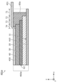
- FIG. 11 is a cross-sectional view of another battery 401a according to this modification.
- the battery 401a includes a unit cell 460a and is formed from one unit cell 460a.
- the unit cell 460a differs from the unit cell 260a according to the second modification in that it has an electrode current collector 410 and a counter electrode current collector 450 instead of the electrode current collector 10 and the counter electrode current collector 50.
- the fourth region 74 is covered with the insulating layer 80a, so a portion of the protrusion 451 is bent and rides up onto the insulating layer 80a that covers the fourth region 74.
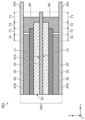
- the battery 501 includes a unit cell 560 and is formed from one unit cell 560.
- the unit cell 560 differs from the unit cell 360 according to the third modification in that it has an electrode current collector 410 and two counter electrode current collectors 450 instead of the electrode current collector 10 and two counter electrode current collectors 50.
- the protrusions 451 of the two counter electrode current collectors 450 face each other via the two insulating layers 80.
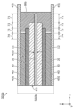
- the battery 501a includes a unit cell 560a and is formed from one unit cell 560a.
- the unit cell 560a differs from the unit cell 360a according to the third modification in that it has an electrode current collector 410 and two counter electrode current collectors 450 instead of the electrode current collector 10 and two counter electrode current collectors 50.
- the protrusions 451 of the two counter electrode current collectors 450 face each other via the two insulating layers 80a.
- FIG. 14 is a cross-sectional view of yet another battery 501b according to this modified example.
- the battery 501b includes a unit cell 560b and is formed from one unit cell 560b.
- the unit cell 560b has a configuration in which the two insulating layers 80 of the unit cell 560 are replaced with an insulating layer 80b.
- the insulating layer 80b covers the end face of the electrode collector 410 in the x-axis positive direction other than the portion where the protrusion 411 is formed. This can further suppress short circuits caused by contact between the protrusion 451 and the electrode collector 410.
- the insulating layer 80b integrally covers the end face of the electrode collector 410 in the x-axis positive direction and the first region 71, the second region 72, and the third region 73 on both main surfaces 11 and 12 of the electrode collector 410.
- the insulating layer 80b does not need to cover other portions of the end face of the electrode collector 410 in the x-axis positive direction as long as it covers the portion that overlaps with the protrusion 451 in a plan view.
- the unit cell 560b may have an insulating layer 80 and another insulating layer that covers the insulating layer 80 and the end face in the x-axis positive direction of the electrode collector 410, instead of the insulating layer 80b that integrally covers the end face in the x-axis positive direction of the electrode collector 410 and the first region 71, the second region 72, and the third region 73 on both main surfaces 11 and 12 of the electrode collector 410.
- the end face in the x-axis positive direction of the electrode collector 410 may be covered with an insulating layer.
- a method for manufacturing the battery according to the present embodiment and each of the modified examples of the present embodiment will be described.
- the following mainly describes a method for manufacturing the battery 501 according to the modified example 5 of the first embodiment, but other batteries can also be manufactured by appropriately applying the manufacturing method described below.
- Fig. 15 is a flow chart showing a method for manufacturing the battery 501 according to the modified example 5 of the first embodiment. Note that the manufacturing method of the battery 501 described below is one example, and the manufacturing method of the battery 501 is not limited to the following example.
- an electrode collector 10 without a protrusion 411 is prepared (step S11).
- an electrode active material layer 20 is laminated on both main surfaces 11 and 12 of the electrode collector 10 (step S12).
- the electrode active material layer 20 is laminated on the main surfaces 11 and 12 so that a first region 71 that is not covered by the electrode active material layer 20 is provided at the end of the main surfaces 11 and 12 in the positive x-axis direction. Note that when manufacturing a battery in which the electrode active material layer 20, etc. is not laminated on the main surface 12 side of the battery 1, etc., the electrode active material layer 20 is laminated only on the main surface 11.
- the solid electrolyte layer 30 is laminated on the electrode active material layer 20 on the side opposite the electrode current collector 10 (step S13). At this time, the solid electrolyte layer 30 is laminated on the electrode active material layer 20 so that a second region 72 that is not covered by the solid electrolyte layer 30 is provided at the end of the electrode active material layer 20 in the positive x-axis direction.
- the counter electrode active material layer 40 is laminated on the side of the solid electrolyte layer 30 opposite the electrode active material layer 20 (step S14). At this time, the counter electrode active material layer 40 is laminated on the solid electrolyte layer 30 so that a third region 73 that is not covered by the counter electrode active material layer 40 is provided at the end of the solid electrolyte layer 30 in the positive x-axis direction.
- step S15 When stacking the electrode active material layer 20, the solid electrolyte layer 30, and the counter electrode active material layer 40, a high-pressure press process (step S15) is performed after each of steps S12 to S14 as necessary. This results in a laminated electrode plate in which the electrode active material layer 20, the solid electrolyte layer 30, and the counter electrode active material layer 40 are stacked in this order from the main surfaces 11 and 12 on both main surfaces 11 and 12 of the electrode collector 10.
- the electrode active material layer 20, the solid electrolyte layer 30, and the counter electrode active material layer 40 are each formed in sequence, for example, by using a wet coating method.
- a wet coating method By using the wet coating method, the electrode active material layer 20, the solid electrolyte layer 30, and the counter electrode active material layer 40 can be easily laminated on the electrode collector 10.
- a coating method such as a die coating method, a doctor blade method, a roll coater method, a screen printing method, or an inkjet method can be used, but is not limited to these methods.
- a coating process is carried out in which the materials forming the electrode active material layer 20, the solid electrolyte layer 30, and the counter electrode active material layer 40 are appropriately mixed with a solvent to obtain a slurry.
- the solvent used in the coating process may be a known solvent used in the manufacture of known all-solid-state batteries (e.g., lithium-ion all-solid-state batteries).
- the slurries for each layer obtained in the coating process are applied to both main surfaces 11 and 12 of the electrode current collector 10 in the order of the electrode active material layer 20, the solid electrolyte layer 30, and the counter electrode active material layer 40.
- the next layer may be applied after the previously applied layer has been applied, or the next layer may be applied while the previously applied layer is being applied.
- steps S12, S13, and S14 may be performed simultaneously in parallel.
- a high-pressure press process (step S15) is performed to promote the filling of the material for each layer.
- the high-pressure press process may be performed after each layer is applied.
- the high-pressure press process may be performed after each layer of the electrode active material layer 20, the solid electrolyte layer 30, and the counter electrode active material layer 40, or may be performed separately after any two layers have been applied and after one layer has been applied, or may be performed all at once after all three layers have been applied.
- the high-pressure press process is performed two or more times, the pressing may be performed so that the pressure of the final high-pressure press process is the highest.
- a roll press, a plate press, or an isostatic press (ISP) is used for the high-pressure press process.
- a heat treatment is performed to remove the solvent before the high-pressure press treatment.
- the heat treatment is performed, for example, after each application of the electrode active material layer 20, the solid electrolyte layer 30, and the counter electrode active material layer 40, but it may also be performed all at once after the electrode active material layer 20, the solid electrolyte layer 30, and the counter electrode active material layer 40 are laminated. Note that at least one of the heat treatment and the high-pressure press treatment does not have to be performed.
- the layered coating method By carrying out the layered coating method in this manner, it is possible to improve the bonding strength at the interface between the electrode collector 10, the electrode active material layer 20, the solid electrolyte layer 30, and the counter electrode active material layer 40, and to reduce the interface resistance. It is also possible to improve the bonding strength and reduce the grain boundary resistance in the powder materials used in the electrode active material layer 20, the solid electrolyte layer 30, and the counter electrode active material layer 40. In other words, good interfaces are formed between the layers of the electrode active material layer 20, the solid electrolyte layer 30, and the counter electrode active material layer 40, and between the powder materials inside each layer.
- steps S12 to S15 above may be performed in a continuous process such as a roll-to-roll process.
- the laminated electrode plate may have a size in plan view corresponding to one battery 501, or may be a size in plan view that can be divided into individual pieces and used for multiple batteries 501.
- FIG. 16 is a top view showing an example of a laminated electrode plate 90. As shown in FIG. 16, the laminated electrode plate 90 has a first region 71, a second region 72, and a third region 73 at both ends on the positive and negative sides of the x-axis.
- the laminated electrode plate 90 has two electrode active material layers 20, two solid electrolyte layers 30, and two counter electrode active material layers 40, and the electrode active material layers 20, the solid electrolyte layers 30, and the counter electrode active material layers 40 are arranged on both sides of the electrode collector 10 in the stacking direction. In FIG. 16, the electrode active material layers 20, the solid electrolyte layers 30, and the counter electrode active material layers 40 arranged on one side (the positive side of the z-axis) of the electrode collector 10 in the stacking direction are shown.
- the battery 501 can also be manufactured by using such laminated electrode plate 90 in the manufacturing process of the battery 501, and then singulating the laminated electrode plate 90 into the shape of a single battery 501 at any stage until the battery 501 is completed.
- This can improve manufacturing efficiency.
- the laminated electrode plate 90 is singulated by cutting at least the laminated electrode plate 90 along the y-axis direction at the center in the x-axis direction. This singulation may also be performed by cutting in step S19, which will be described later. After singulation of the laminated electrode plate 90, polishing or the like may be performed to adjust the size.
- the electrode collector 410 is formed by forming the protrusion 411 on the electrode collector 10 (step S16).
- the protrusion 411 is formed, for example, by removing a part of the first region 71.
- a blade such as a cutter, a slitter, a cutting machine, a punching machine with a Thompson blade, a laser, a jet, or other means may be used, but is not limited to these methods.
- a foil or the like having the shape of the protrusion 411 that is prepared separately may be joined to the electrode collector 10.
- a means such as ultrasonic welding, resistance welding, and crimping may be used, but is not limited to these methods.
- the protrusion 411 may be formed at any stage in the manufacture of the battery 501.
- the electrode collector 410 on which the protrusion 411 is formed in advance may be prepared.
- an insulating layer 80 is formed so as to cover a part of the first region 71 on the second region 72 side, the entire second region 72, and a part of the third region 73 on the second region 72 side (step S17).
- the insulating layer 80 is arranged, for example, by applying and curing a resin material having flowability. The application is performed by an inkjet method or a screen printing method, or by dipping the end face of the laminated electrode plate in the resin material. The curing is performed by drying, heating, or light irradiation, depending on the resin material used.
- the insulating layer 80 when forming the insulating layer 80, a part of the first region 71 may be protected by masking with tape or resist processing so that the entire first region 71 of the main surfaces 11 and 12 of the electrode collector 10 is not insulated. After the insulating layer 80 is formed, the member used for protection as described above is removed to ensure electrical connection in the first region 71.
- the insulating layer 80 may also be formed by attaching an insulating tape, but is not limited to these methods.
- the insulating layer 80a is formed so as to cover the entire third region 73 and a part of the fourth region 74 on the third region 73 side.
- the insulating layer 80b is formed so as to cover the end face of the electrode collector 410 in addition to the region covered by the insulating layer 80.
- the counter electrode current collector 450 is laminated on the opposite side of the counter electrode active material layer 40 from the solid electrolyte layer 30 (step S18). This results in a laminate (unit cell 560) in which the electrode active material layer 20, the solid electrolyte layer 30, the counter electrode active material layer 40, and the counter electrode current collector 450 are laminated in this order on both main surfaces 11 and 12 of the electrode current collector 410. At this time, the counter electrode current collector 450 is laminated on the counter electrode active material layer 40 so that a fourth region 74 that is not covered by the counter electrode current collector 450 is provided at the end of the counter electrode active material layer 40 in the x-axis positive direction.
- the counter electrode active material layer 40 and the counter electrode current collector 450 are bonded to each other by, for example, a high-pressure press treatment or the like.
- the bonding may also be performed by using a counter electrode current collector 450 having a connection layer containing an adhesive binder, coating an adhesive, or attaching an adhesive film.
- the bonding method is not limited to these methods. Heat treatment may also be performed during or after bonding.
- the counter electrode collector 450 may be formed to the desired dimensions prior to stacking, or a portion of it may be removed after stacking. Also, a protrusion 451 may be formed after stacking.
- the unit cell 560 obtained in step S18 is cut along a direction intersecting the main surface 11 to form cut surfaces as side surfaces 62, 63, and 64 at the ends of the unit cell 560 in the negative x-axis direction, the positive y-axis direction, and the negative y-axis direction (step S19).
- This cutting forms three sides that constitute the ends of the unit cell 560 in the negative x-axis direction, the positive y-axis direction, and the negative y-axis direction, which are different from the ends where the first region 71, the second region 72, the third region 73, and the fourth region 74 are provided, in a plan view.
- a cutter for cutting, a cutter, an ultrasonic cutter, a slitter, a dicer, a cutting machine, a punching machine with a Thompson blade, or other blades, a laser, a jet, or other means are used, but are not limited to these methods.
- the side surfaces 62, 63, and 64 may be polished after cutting to remove burrs, etc.
- step S19 the electrode collector 410, the electrode active material layer 20, the solid electrolyte layer 30, the counter electrode active material layer 40, and the counter electrode collector 450 are cut together along a direction intersecting the main surface 11.
- the direction intersecting the main surface 11 is specifically a direction perpendicular to the main surface 11, and can also be said to be the stacking direction of the unit cells 560. This makes it possible to easily manufacture the battery 501, since it is not necessary to stack the electrode collector 410, the electrode active material layer 20, the solid electrolyte layer 30, the counter electrode active material layer 40, and the counter electrode collector 450 in the shape after cutting.
- the region in which the first region 71, the second region 72, the third region 73, and the fourth region 74 are provided remains uncut, it is possible to form the terminal in a structure that can suppress the occurrence of a short circuit. Therefore, it is possible to easily manufacture a highly reliable battery 501.
- the capacity of the unit cell 560 can be adjusted at the position where the unit cell 560 is cut, the capacity accuracy can be improved.
- the respective side surfaces of the electrode collector 410, electrode active material layer 20, solid electrolyte layer 30, counter electrode active material layer 40, and counter electrode collector 450 are exposed.
- a sealing member or the like that covers these exposed side surfaces may be placed to protect these side surfaces. In other words, when these side surfaces are covered with another member such as a sealing member, these exposed side surfaces may also be covered with the other member.
- a battery 501 consisting of one unit cell 560 is obtained.
- the obtained battery 501 may be housed in an exterior body or the like.
- the protrusions 411 and 451 are pulled out to the outside of the exterior body.
- the obtained battery 501 may be subjected to a process of removing corners (intersections of the sides) in a plan view by cutting or the like. In this case, when cutting off a corner in the positive x-axis direction, for example, a portion including the first region 71, the second region 72, the third region 73, and the fourth region 74 is removed. This removes corners that are prone to collapse and breakage, and further improves the reliability of the battery 501.
- step S19 the laminate (laminated electrode plate) in which the electrode collector 410, the electrode active material layer 20, the solid electrolyte layer 30, and the counter electrode active material layer 40 are laminated is cut along a direction intersecting with the main surface 11 to form cut surfaces at the ends of the laminated electrode plate in the x-axis negative direction, the y-axis positive direction, and the y-axis negative direction.
- the electrode collector 410, the electrode active material layer 20, the solid electrolyte layer 30, and the counter electrode active material layer 40 are cut together along a direction intersecting with the main surface 11.
- step S18 a counter electrode current collector 450 having a shape corresponding to the shape of the laminated electrode plate after the cut surface is formed is laminated on the opposite side of the counter electrode active material layer 40 from the solid electrolyte layer 30. This results in a battery 501 composed of one unit cell 560.
- Fig. 17 is a cross-sectional view of a battery 601 according to this embodiment.
- the battery 601 includes a plurality of unit cells 560 according to the fifth modification of the first embodiment, and has a structure in which the plurality of unit cells 560 are stacked. Since the unit cells 560 are stacked in the battery 601, a highly reliable battery 601 can be realized.
- the multiple unit cells 560 have the same configuration and are stacked so that they can be electrically connected in parallel.
- the electrode active material layer 20, the solid electrolyte layer 30, and the counter electrode active material layer 40 stacked on the main surfaces on both sides of each current collector are stacked in the same order from the current collector.
- the multiple unit cells 560 are stacked so that the positions of the side surfaces of the unit cells 560 match when viewed from the stacking direction. Therefore, the side surfaces of each of the multiple unit cells 560 in the negative x-axis direction, the positive y-axis direction, and the negative y-axis direction are flush with each other.
- the protrusions 451 and the protrusions 411 protrude in the same direction, specifically in the positive x-axis direction.
- the protrusions 451 of the multiple unit cells 560 and the protrusions 411 of the multiple unit cells 560 may be bundled together and joined by welding or the like.
- the number of stacked unit cells 560 is four, but it may be two or three, or it may be five or more.
- two adjacent unit cells 560 share the counter electrode current collector 450.
- the two adjacent unit cells 560 may not share the counter electrode current collector 450, and each of the two adjacent unit cells 560 may have an individual counter electrode current collector 450, with two counter electrode current collectors 450 overlapping between the counter electrode active material layers 40.
- a conductive adhesive layer may be provided between the two counter electrode current collectors 450.
- the unit cells according to the first embodiment and each of the modified examples described above may be used instead of the unit cell 560 as the unit cells to be stacked. Even when unit cells other than the unit cell 560 are stacked, adjacent unit cells may share a current collector, or the unit cells may be stacked so that two separate current collectors are stacked without sharing a current collector. In addition, when unit cells in which the electrode active material layer 20, the solid electrolyte layer 30, the counter electrode active material layer 40, and the counter electrode current collector 50 or 450 are stacked only on one main surface 11 of the electrode current collector 10 or 410, such as the unit cell 60, are stacked, the unit cells may be stacked so as to be electrically connected in series.
- the multiple unit cells may include unit cells having different configurations from each other.
- the multiple unit cells may include unit cells having different configurations from the unit cells according to the first embodiment and each of the modified examples.
- the multiple unit cells in this case may include a unit cell in which the side surfaces of the electrode collector 10, the electrode active material layer 20, the solid electrolyte layer 30, the counter electrode active material layer 40, and the counter electrode collector 50 are flush with each other on all sides.
- FIG. 18 is a cross-sectional view of another battery 601a according to this embodiment.
- FIG. 18 shows battery 601a in which multiple unit cells 560a are stacked.
- the battery 601a has a configuration in which the multiple unit cells 560 of the battery 601 are replaced with multiple unit cells 560a.
- the multiple unit cells 560a are stacked and joined together by pressing or the like, so that in the area where the protrusion 451 of the counter electrode collector 450 and the insulating layer 80a overlap in a plan view, the protrusion 451 and the insulating layer 80a are rolled, and the gap between the counter electrode collector 450 and the insulating layer 80a provided in the example shown in FIG. 11 is filled with the insulating layer 80a.
- the bottom and top of the battery 601a may have a structure in which the protrusion 451 rides up onto the insulating layer 80a as shown in FIG. 11.
- a method for manufacturing the battery according to the present embodiment will be described.
- the following will mainly describe a method for manufacturing the battery 601 in which a plurality of unit cells 560 are stacked, but a battery in which unit cells other than the unit cells 560 according to the first embodiment and each of the modified examples described above are stacked can also be manufactured by appropriately applying the manufacturing method described below.
- Fig. 19 is a flow chart showing a method for manufacturing the battery 601 according to the second embodiment. Note that the manufacturing method for the battery 601 described below is one example, and the manufacturing method for the battery 601 is not limited to the following example.
- laminated plates are formed in the same number as the number of unit cells 560 in the battery 601 by a method similar to steps S11 to S17 shown in FIG. 15 and described above.
- the laminated plates may be large laminated plates 90 with an insulating layer 80 formed thereon as shown in FIG. 16, or laminated plates corresponding to the size of the unit cells 560. Note that steps S21 to S27 may be omitted, and the same number of laminated plates as the number of unit cells 560 in the preformed battery 601 may be prepared.
- the counter electrode current collector 450 is laminated on the side of the counter electrode active material layer 40 opposite the solid electrolyte layer 30, and multiple unit cells 560 are laminated (steps S28 and S29).
- the multiple laminated electrode plates and multiple counter electrode current collectors 450 obtained up to step S27 are laminated so that the counter electrode current collector 450 is laminated on the side of the counter electrode active material layer 40 opposite the solid electrolyte layer 30.
- the laminated electrode plate has only the electrode current collector 410 as a collector, and does not have the counter electrode current collector 450. Therefore, when stacking the multiple laminated electrode plates and the multiple counter electrode current collectors 450, it is possible to share one counter electrode current collector 450 with adjacent unit cells 560 without overlapping the counter electrode current collectors 450.
- the counter electrode collector 450 and the laminated electrode plates obtained up to step S27 are alternately stacked, so that the counter electrode collector 450 is shared by the adjacent unit cells 560, and the counter electrode collector 450 is stacked on the counter electrode active material layer 40 and multiple unit cells 560 are stacked.
- the counter electrode collector 450 may be stacked on only one of the two counter electrode active material layers 40 of the laminated electrode plate to form a unit cell having a structure in which one counter electrode collector 450 is removed from the unit cell 560, and this unit cell may be stacked.
- the counter electrode collector 450 may also be shared by the adjacent unit cells 560 by stacking this unit cell so that the counter electrode collector 450 is sandwiched between the counter electrode active material layers 40. In this case, after stacking the required number of unit cells, the counter electrode current collector 450 is stacked on the counter electrode active material layer 40 at the end in the stacking direction, on which the counter electrode current collector 450 is not stacked.
- the counter electrode active material layer 40 and the counter electrode current collector 450 may be joined by a high-pressure press process or the like, as in step S18.
- This joining may be performed at an intermediate stage in the stacking of the counter electrode current collector 450 and the laminated electrode plate, or may be performed all at once after stacking all of the counter electrode current collectors 450 and the laminated electrode plates.
- the joining is performed all at once, for example, all of the multiple counter electrode current collectors 450 and the multiple laminated electrode plates are stacked and pressed all at once after stacking. This makes it possible to reduce the number of handling operations, and prevents foreign matter from being caught in the stacking of the multiple laminated electrode plates and the multiple counter electrode current collectors 450, making it possible to manufacture a highly reliable battery.
- the counter electrode collector 450 may be formed to the desired dimensions prior to stacking, or a portion of the counter electrode collector 450 may be removed after stacking. Also, a protrusion 451 may be formed after stacking.
- step S28 a process similar to step S18 described above is performed as step S28 to obtain a laminate (unit cell 560) in which the electrode active material layer 20, the solid electrolyte layer 30, the counter electrode active material layer 40, and the counter electrode collector 450 are laminated in this order on both main surfaces 11 and 12 of the electrode collector 410. Then, in step S29, the obtained unit cells 560 are laminated. At this time, the unit cells 560 are bonded to each other by a conductive adhesive layer formed by coating an adhesive or laminating an adhesive film.
- the bonding method is not limited to these methods.
- heat treatment and pressing may be performed after bonding.
- all of the counter electrode collectors 450 and the laminated electrode plates may be laminated by stacking the unit cells 560, and then pressed together after stacking.
- step S30 the stack of the unit cells 560 obtained in step S29 is cut along a direction intersecting the main surface 11 to form cut surfaces as side surfaces 62, 63, and 64 at the ends of the unit cells 560 in the negative x-axis direction, the positive y-axis direction, and the negative y-axis direction (step S30).
- This cutting forms three sides that constitute the ends of the unit cells 560 different from the ends where the first region 71, the second region 72, the third region 73, and the fourth region 74 are provided in a plan view.
- the cutting method can be performed in the same manner as in step S19 above.
- step S30 all the unit cells 560 are cut together along a direction intersecting the main surface 11.
- the battery 601 makes it possible to easily manufacture the battery 601 because it is not necessary to stack the electrode collector 410, the electrode active material layer 20, the solid electrolyte layer 30, the counter electrode active material layer 40, and the counter electrode collector 450 of each of the unit cells 560 in the shape after cutting.
- the areas where the first region 71, the second region 72, the third region 73, and the fourth region 74 are provided remain uncut, so it is possible to form the terminals in a structure that can suppress the occurrence of short circuits. Therefore, a highly reliable battery 601 can be easily manufactured.
- the side surfaces of the electrode collector 410, electrode active material layer 20, solid electrolyte layer 30, counter electrode active material layer 40, and counter electrode collector 450 of each of the multiple unit cells 560 are exposed.
- a sealing member or the like that covers these exposed side surfaces may be placed to protect these side surfaces. In other words, when these side surfaces are covered with another member such as a sealing member, these exposed side surfaces may also be covered with the other member.
- a battery 601 having a structure in which a plurality of unit cells 560 are stacked is obtained.
- the obtained battery 601 may be housed in an exterior body or the like.
- the protrusions 411 and 451 are pulled out to the outside of the exterior body.
- the obtained battery 601 may be subjected to a process of removing corners (intersections of the side surfaces) in a plan view by cutting or the like.
- step S30 the formation of the cut surfaces in step S30 may be performed before step S29.
- step S29 the unit cells with the cut surfaces formed are stacked to obtain the battery 601.
- the laminated electrode plate and counter electrode collector 450 laminated in steps S28 and S29 are not limited to a configuration corresponding to the plurality of unit cells 560, and may be a laminated electrode plate and counter electrode collector having a configuration corresponding to the battery to be manufactured.
- the laminated electrode plate and counter electrode collector used in steps S28 and S29 may have a configuration corresponding to the unit cell according to the above-described embodiment 1 and each of the modified examples other than the unit cell 560.
- the laminated electrode plate used in steps S28 and S29 may include a laminated electrode plate in which the side surfaces of the electrode collector 10, the electrode active material layer 20, the solid electrolyte layer 30, and the counter electrode active material layer 40 are flush with each other on all sides.
- the battery is composed of an electrode collector, an electrode active material layer, a solid electrolyte layer, a counter electrode active material layer, and a counter electrode collector, or an electrode collector, an electrode active material layer, a solid electrolyte layer, a counter electrode active material layer, a counter electrode collector, and an insulating layer, but is not limited to this.
- a bonding layer or the like for reducing electrical resistance and improving bonding strength may be provided between each layer of the battery.
- the electrode active material layer, solid electrolyte layer, and counter electrode active material layer are formed by sequentially stacking them directly on the main surface side of the electrode collector, but this is not limited to the above.
- the electrode active material layer, solid electrolyte layer, and counter electrode active material layer may be formed by sequentially stacking them on a sheet-like substrate, and the formed electrode active material layer, solid electrolyte layer, and counter electrode active material layer may be removed from the substrate and stacked on the main surface of the electrode collector.
- the electrode active material layer, solid electrolyte layer, and counter electrode active material layer may be formed on a sheet-like substrate, and the formed electrode active material layer, solid electrolyte layer, and counter electrode active material layer may be stacked by sequentially transferring them to the main surface of the electrode collector.
- the unit cell is provided with the first region, the second region, the third region, and the fourth region, but this is not limited to the above.
- the counter electrode active material layer may be completely covered by the counter electrode current collector, and the fourth region may not be provided.
- the battery according to the present disclosure can be used, for example, as a secondary battery such as an all-solid-state battery for use in various electronic devices, electrical appliances, or automobiles.
Landscapes
- Battery Electrode And Active Subsutance (AREA)
- Secondary Cells (AREA)
Priority Applications (3)
| Application Number | Priority Date | Filing Date | Title |
|---|---|---|---|
| EP24831465.0A EP4738522A1 (en) | 2023-06-28 | 2024-05-17 | Battery and battery manufacturing method |
| CN202480041998.1A CN121368827A (zh) | 2023-06-28 | 2024-05-17 | 电池以及电池的制造方法 |
| JP2025529507A JPWO2025004593A1 (cg-RX-API-DMAC7.html) | 2023-06-28 | 2024-05-17 |
Applications Claiming Priority (2)
| Application Number | Priority Date | Filing Date | Title |
|---|---|---|---|
| JP2023106267 | 2023-06-28 | ||
| JP2023-106267 | 2023-06-28 |
Publications (1)
| Publication Number | Publication Date |
|---|---|
| WO2025004593A1 true WO2025004593A1 (ja) | 2025-01-02 |
Family
ID=93938509
Family Applications (1)
| Application Number | Title | Priority Date | Filing Date |
|---|---|---|---|
| PCT/JP2024/018297 Ceased WO2025004593A1 (ja) | 2023-06-28 | 2024-05-17 | 電池および電池の製造方法 |
Country Status (4)
| Country | Link |
|---|---|
| EP (1) | EP4738522A1 (cg-RX-API-DMAC7.html) |
| JP (1) | JPWO2025004593A1 (cg-RX-API-DMAC7.html) |
| CN (1) | CN121368827A (cg-RX-API-DMAC7.html) |
| WO (1) | WO2025004593A1 (cg-RX-API-DMAC7.html) |
Citations (8)
| Publication number | Priority date | Publication date | Assignee | Title |
|---|---|---|---|---|
| JPH10284130A (ja) * | 1997-04-04 | 1998-10-23 | Nec Corp | 半導体基板搭載型二次電池 |
| JP2018152280A (ja) * | 2017-03-14 | 2018-09-27 | 株式会社アルバック | 積層型ミニチュアライズ薄膜電池及びその製造方法 |
| JP2019140079A (ja) | 2018-02-06 | 2019-08-22 | トヨタ自動車株式会社 | 積層電池 |
| JP2020129519A (ja) | 2019-02-12 | 2020-08-27 | トヨタ自動車株式会社 | 全固体電池 |
| WO2020183795A1 (ja) * | 2019-03-12 | 2020-09-17 | パナソニックIpマネジメント株式会社 | 積層電池 |
| JP2021026877A (ja) * | 2019-08-05 | 2021-02-22 | 国立大学法人神戸大学 | 全固体薄膜電池及びその製造方法 |
| WO2022159985A1 (en) * | 2021-01-25 | 2022-07-28 | Blue Current, Inc. | Solid-state lithium ion multilayer battery and manufacturing method |
| WO2023089874A1 (ja) * | 2021-11-19 | 2023-05-25 | パナソニックIpマネジメント株式会社 | 電池、電池の製造方法および回路基板 |
-
2024
- 2024-05-17 JP JP2025529507A patent/JPWO2025004593A1/ja active Pending
- 2024-05-17 CN CN202480041998.1A patent/CN121368827A/zh active Pending
- 2024-05-17 WO PCT/JP2024/018297 patent/WO2025004593A1/ja not_active Ceased
- 2024-05-17 EP EP24831465.0A patent/EP4738522A1/en active Pending
Patent Citations (8)
| Publication number | Priority date | Publication date | Assignee | Title |
|---|---|---|---|---|
| JPH10284130A (ja) * | 1997-04-04 | 1998-10-23 | Nec Corp | 半導体基板搭載型二次電池 |
| JP2018152280A (ja) * | 2017-03-14 | 2018-09-27 | 株式会社アルバック | 積層型ミニチュアライズ薄膜電池及びその製造方法 |
| JP2019140079A (ja) | 2018-02-06 | 2019-08-22 | トヨタ自動車株式会社 | 積層電池 |
| JP2020129519A (ja) | 2019-02-12 | 2020-08-27 | トヨタ自動車株式会社 | 全固体電池 |
| WO2020183795A1 (ja) * | 2019-03-12 | 2020-09-17 | パナソニックIpマネジメント株式会社 | 積層電池 |
| JP2021026877A (ja) * | 2019-08-05 | 2021-02-22 | 国立大学法人神戸大学 | 全固体薄膜電池及びその製造方法 |
| WO2022159985A1 (en) * | 2021-01-25 | 2022-07-28 | Blue Current, Inc. | Solid-state lithium ion multilayer battery and manufacturing method |
| WO2023089874A1 (ja) * | 2021-11-19 | 2023-05-25 | パナソニックIpマネジメント株式会社 | 電池、電池の製造方法および回路基板 |
Also Published As
| Publication number | Publication date |
|---|---|
| JPWO2025004593A1 (cg-RX-API-DMAC7.html) | 2025-01-02 |
| EP4738522A1 (en) | 2026-05-06 |
| CN121368827A (zh) | 2026-01-20 |
Similar Documents
| Publication | Publication Date | Title |
|---|---|---|
| JP7745181B2 (ja) | 電池 | |
| JP7692156B2 (ja) | 電池 | |
| US20220302462A1 (en) | Battery | |
| JP7437710B2 (ja) | 積層電池 | |
| US20240258666A1 (en) | Battery and method for manufacturing battery | |
| WO2025243576A1 (ja) | 電池 | |
| WO2022172618A1 (ja) | 電池および電池の製造方法 | |
| CN115244753A (zh) | 层叠电池的制造方法 | |
| US20230307717A1 (en) | Battery, laminated battery, and method for manufacturing same | |
| US20240128620A1 (en) | Battery | |
| US20240088348A1 (en) | Battery and method for manufacturing battery | |
| US12315868B2 (en) | Method for manufacturing battery | |
| WO2025004593A1 (ja) | 電池および電池の製造方法 | |
| JP2023172252A (ja) | 電池の製造方法および電池 | |
| WO2022270141A1 (ja) | 電池及び電池の製造方法 | |
| WO2023145223A1 (ja) | 電池および電池の製造方法 | |
| WO2025243578A1 (ja) | 電池および電池の製造方法 | |
| JP2026003429A (ja) | 電池 | |
| WO2026009502A1 (ja) | 電池およびその製造方法 | |
| JP7837007B2 (ja) | 電池および電池の製造方法 | |
| WO2025004594A1 (ja) | 電池および電池の製造方法 | |
| WO2025263026A1 (ja) | 電池 | |
| WO2025263027A1 (ja) | 電池 | |
| CN116636030A (zh) | 电池、层叠电池及其制造方法 | |
| WO2025134550A1 (ja) | 電池および電池の製造方法 |
Legal Events
| Date | Code | Title | Description |
|---|---|---|---|
| 121 | Ep: the epo has been informed by wipo that ep was designated in this application |
Ref document number: 24831465 Country of ref document: EP Kind code of ref document: A1 |
|
| ENP | Entry into the national phase |
Ref document number: 2025529507 Country of ref document: JP Kind code of ref document: A |
|
| WWE | Wipo information: entry into national phase |
Ref document number: 2025529507 Country of ref document: JP |
|
| WWE | Wipo information: entry into national phase |
Ref document number: 2024831465 Country of ref document: EP |
|
| NENP | Non-entry into the national phase |
Ref country code: DE |
|
| ENP | Entry into the national phase |
Ref document number: 2024831465 Country of ref document: EP Effective date: 20260128 |
|
| ENP | Entry into the national phase |
Ref document number: 2024831465 Country of ref document: EP Effective date: 20260128 |