WO2025004566A1 - ソレノイド、緩衝器及びソレノイドの製造方法 - Google Patents
ソレノイド、緩衝器及びソレノイドの製造方法 Download PDFInfo
- Publication number
- WO2025004566A1 WO2025004566A1 PCT/JP2024/017721 JP2024017721W WO2025004566A1 WO 2025004566 A1 WO2025004566 A1 WO 2025004566A1 JP 2024017721 W JP2024017721 W JP 2024017721W WO 2025004566 A1 WO2025004566 A1 WO 2025004566A1
- Authority
- WO
- WIPO (PCT)
- Prior art keywords
- solenoid
- coil
- large diameter
- diameter portion
- bobbin
- Prior art date
- Legal status (The legal status is an assumption and is not a legal conclusion. Google has not performed a legal analysis and makes no representation as to the accuracy of the status listed.)
- Ceased
Links
Images





Classifications
-
- H—ELECTRICITY
- H01—ELECTRIC ELEMENTS
- H01F—MAGNETS; INDUCTANCES; TRANSFORMERS; SELECTION OF MATERIALS FOR THEIR MAGNETIC PROPERTIES
- H01F7/00—Magnets
- H01F7/06—Electromagnets; Actuators including electromagnets
- H01F7/08—Electromagnets; Actuators including electromagnets with armatures
- H01F7/16—Rectilinearly-movable armatures
- H01F7/1607—Armatures entering the winding
-
- B—PERFORMING OPERATIONS; TRANSPORTING
- B60—VEHICLES IN GENERAL
- B60G—VEHICLE SUSPENSION ARRANGEMENTS
- B60G13/00—Resilient suspensions characterised by arrangement, location or type of vibration dampers
- B60G13/02—Resilient suspensions characterised by arrangement, location or type of vibration dampers having dampers dissipating energy, e.g. frictionally
- B60G13/06—Resilient suspensions characterised by arrangement, location or type of vibration dampers having dampers dissipating energy, e.g. frictionally of fluid type
- B60G13/08—Resilient suspensions characterised by arrangement, location or type of vibration dampers having dampers dissipating energy, e.g. frictionally of fluid type hydraulic
-
- B—PERFORMING OPERATIONS; TRANSPORTING
- B60—VEHICLES IN GENERAL
- B60G—VEHICLE SUSPENSION ARRANGEMENTS
- B60G17/00—Resilient suspensions having means for adjusting the spring or vibration-damper characteristics, for regulating the distance between a supporting surface and a sprung part of vehicle or for locking suspension during use to meet varying vehicular or surface conditions, e.g. due to speed or load
- B60G17/02—Spring characteristics, e.g. mechanical springs and mechanical adjusting means
- B60G17/04—Spring characteristics, e.g. mechanical springs and mechanical adjusting means fluid spring characteristics
-
- F—MECHANICAL ENGINEERING; LIGHTING; HEATING; WEAPONS; BLASTING
- F16—ENGINEERING ELEMENTS AND UNITS; GENERAL MEASURES FOR PRODUCING AND MAINTAINING EFFECTIVE FUNCTIONING OF MACHINES OR INSTALLATIONS; THERMAL INSULATION IN GENERAL
- F16F—SPRINGS; SHOCK-ABSORBERS; MEANS FOR DAMPING VIBRATION
- F16F9/00—Springs, vibration-dampers, shock-absorbers, or similarly-constructed movement-dampers using a fluid or the equivalent as damping medium
- F16F9/32—Details
- F16F9/3207—Constructional features
- F16F9/3235—Constructional features of cylinders
- F16F9/325—Constructional features of cylinders for attachment of valve units
-
- F—MECHANICAL ENGINEERING; LIGHTING; HEATING; WEAPONS; BLASTING
- F16—ENGINEERING ELEMENTS AND UNITS; GENERAL MEASURES FOR PRODUCING AND MAINTAINING EFFECTIVE FUNCTIONING OF MACHINES OR INSTALLATIONS; THERMAL INSULATION IN GENERAL
- F16F—SPRINGS; SHOCK-ABSORBERS; MEANS FOR DAMPING VIBRATION
- F16F9/00—Springs, vibration-dampers, shock-absorbers, or similarly-constructed movement-dampers using a fluid or the equivalent as damping medium
- F16F9/32—Details
- F16F9/34—Special valve constructions; Shape or construction of throttling passages
- F16F9/346—Throttling passages in the form of slots arranged in cylinder walls
-
- F—MECHANICAL ENGINEERING; LIGHTING; HEATING; WEAPONS; BLASTING
- F16—ENGINEERING ELEMENTS AND UNITS; GENERAL MEASURES FOR PRODUCING AND MAINTAINING EFFECTIVE FUNCTIONING OF MACHINES OR INSTALLATIONS; THERMAL INSULATION IN GENERAL
- F16F—SPRINGS; SHOCK-ABSORBERS; MEANS FOR DAMPING VIBRATION
- F16F9/00—Springs, vibration-dampers, shock-absorbers, or similarly-constructed movement-dampers using a fluid or the equivalent as damping medium
- F16F9/32—Details
- F16F9/44—Means on or in the damper for manual or non-automatic adjustment; such means combined with temperature correction
- F16F9/46—Means on or in the damper for manual or non-automatic adjustment; such means combined with temperature correction allowing control from a distance, i.e. location of means for control input being remote from site of valves, e.g. on damper external wall
- F16F9/461—Means on or in the damper for manual or non-automatic adjustment; such means combined with temperature correction allowing control from a distance, i.e. location of means for control input being remote from site of valves, e.g. on damper external wall characterised by actuation means
-
- F—MECHANICAL ENGINEERING; LIGHTING; HEATING; WEAPONS; BLASTING
- F16—ENGINEERING ELEMENTS AND UNITS; GENERAL MEASURES FOR PRODUCING AND MAINTAINING EFFECTIVE FUNCTIONING OF MACHINES OR INSTALLATIONS; THERMAL INSULATION IN GENERAL
- F16F—SPRINGS; SHOCK-ABSORBERS; MEANS FOR DAMPING VIBRATION
- F16F9/00—Springs, vibration-dampers, shock-absorbers, or similarly-constructed movement-dampers using a fluid or the equivalent as damping medium
- F16F9/32—Details
- F16F9/44—Means on or in the damper for manual or non-automatic adjustment; such means combined with temperature correction
- F16F9/46—Means on or in the damper for manual or non-automatic adjustment; such means combined with temperature correction allowing control from a distance, i.e. location of means for control input being remote from site of valves, e.g. on damper external wall
- F16F9/465—Means on or in the damper for manual or non-automatic adjustment; such means combined with temperature correction allowing control from a distance, i.e. location of means for control input being remote from site of valves, e.g. on damper external wall using servo control, the servo pressure being created by the flow of damping fluid, e.g. controlling pressure in a chamber downstream of a pilot passage
-
- F—MECHANICAL ENGINEERING; LIGHTING; HEATING; WEAPONS; BLASTING
- F16—ENGINEERING ELEMENTS AND UNITS; GENERAL MEASURES FOR PRODUCING AND MAINTAINING EFFECTIVE FUNCTIONING OF MACHINES OR INSTALLATIONS; THERMAL INSULATION IN GENERAL
- F16K—VALVES; TAPS; COCKS; ACTUATING-FLOATS; DEVICES FOR VENTING OR AERATING
- F16K31/00—Actuating devices; Operating means; Releasing devices
- F16K31/02—Actuating devices; Operating means; Releasing devices electric; magnetic
- F16K31/06—Actuating devices; Operating means; Releasing devices electric; magnetic using a magnet, e.g. diaphragm valves, cutting off by means of a liquid
-
- H—ELECTRICITY
- H01—ELECTRIC ELEMENTS
- H01F—MAGNETS; INDUCTANCES; TRANSFORMERS; SELECTION OF MATERIALS FOR THEIR MAGNETIC PROPERTIES
- H01F27/00—Details of transformers or inductances, in general
- H01F27/28—Coils; Windings; Conductive connections
- H01F27/32—Insulating of coils, windings, or parts thereof
- H01F27/324—Insulation between coil and core, between different winding sections, around the coil; Other insulation structures
- H01F27/325—Coil bobbins
-
- H—ELECTRICITY
- H01—ELECTRIC ELEMENTS
- H01F—MAGNETS; INDUCTANCES; TRANSFORMERS; SELECTION OF MATERIALS FOR THEIR MAGNETIC PROPERTIES
- H01F5/00—Coils
- H01F5/02—Coils wound on non-magnetic supports, e.g. formers
-
- H—ELECTRICITY
- H01—ELECTRIC ELEMENTS
- H01F—MAGNETS; INDUCTANCES; TRANSFORMERS; SELECTION OF MATERIALS FOR THEIR MAGNETIC PROPERTIES
- H01F7/00—Magnets
- H01F7/06—Electromagnets; Actuators including electromagnets
- H01F7/08—Electromagnets; Actuators including electromagnets with armatures
- H01F7/127—Assembling
-
- H—ELECTRICITY
- H01—ELECTRIC ELEMENTS
- H01F—MAGNETS; INDUCTANCES; TRANSFORMERS; SELECTION OF MATERIALS FOR THEIR MAGNETIC PROPERTIES
- H01F7/00—Magnets
- H01F7/06—Electromagnets; Actuators including electromagnets
- H01F7/08—Electromagnets; Actuators including electromagnets with armatures
- H01F7/128—Encapsulating, encasing or sealing
-
- H—ELECTRICITY
- H01—ELECTRIC ELEMENTS
- H01F—MAGNETS; INDUCTANCES; TRANSFORMERS; SELECTION OF MATERIALS FOR THEIR MAGNETIC PROPERTIES
- H01F7/00—Magnets
- H01F7/06—Electromagnets; Actuators including electromagnets
- H01F7/08—Electromagnets; Actuators including electromagnets with armatures
- H01F7/16—Rectilinearly-movable armatures
-
- B—PERFORMING OPERATIONS; TRANSPORTING
- B60—VEHICLES IN GENERAL
- B60G—VEHICLE SUSPENSION ARRANGEMENTS
- B60G2202/00—Indexing codes relating to the type of spring, damper or actuator
- B60G2202/20—Type of damper
- B60G2202/24—Fluid damper
-
- B—PERFORMING OPERATIONS; TRANSPORTING
- B60—VEHICLES IN GENERAL
- B60G—VEHICLE SUSPENSION ARRANGEMENTS
- B60G2204/00—Indexing codes related to suspensions per se or to auxiliary parts
- B60G2204/10—Mounting of suspension elements
- B60G2204/20—Mounting of accessories, e.g. pump, compressor
-
- B—PERFORMING OPERATIONS; TRANSPORTING
- B60—VEHICLES IN GENERAL
- B60G—VEHICLE SUSPENSION ARRANGEMENTS
- B60G2500/00—Indexing codes relating to the regulated action or device
- B60G2500/10—Damping action or damper
- B60G2500/11—Damping valves
Definitions
- the present invention relates to a solenoid for a solenoid valve, a shock absorber, and a method for manufacturing the solenoid.
- Patent Document 1 describes a molded coil in which a coil is wound between frame disks provided near both ends of a cylindrical coil bobbin made of thermoplastic resin, protrusions are formed on the outer and outer peripheral surfaces of the frame disks that continue in the circumferential direction and have thin-walled sections at their tips, and a molten high-temperature molding material made of the same resin is injection molded onto the outer peripheral part of the coil bobbin, whereby the thin-walled sections are heated and melted by the molding material, and the two are heat-fused together (see abstract).
- the molded coil of Patent Document 1 has a structure in which the ridges on the end face of the coil bobbin are melted, so it is necessary to inject molding material onto the end face of the coil bobbin, and the molding material on the end face of the coil bobbin increases the axial length of the coil.
- the object of the present invention is to provide a solenoid structure that can shorten the axial length.
- the solenoid of the present invention comprises: A solenoid mounted on a solenoid valve,
- the solenoid is a bobbin having a cylindrical portion and a large diameter portion formed at one end of the cylindrical portion and extending radially outward from the cylindrical portion; a coil wound around the cylindrical portion of the bobbin; a primary exterior body covering an outer periphery of the coil and a side surface of the large diameter portion of the bobbin and forming a seal between the primary exterior body and the side surface of the large diameter portion of the bobbin; having Of both end faces of the large diameter portion, at least a portion of the end face opposite the side on which the coil is wound is exposed from the primary exterior body.
- the axial length of the solenoid can be shortened by providing a seal on the side surface of the large diameter portion of the bobbin and eliminating the seal on the end surface of the large diameter portion.
- FIG. 1 is a vertical cross-sectional view of a solenoid according to an embodiment of the present invention.
- FIG. 2 is a vertical cross-sectional view showing a molded coil taken out from the solenoid of FIG. 1.
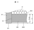
- 3 is an enlarged view of the vicinity of the side surface of the large diameter portion of the molded coil (part III in FIG. 2 ).
- FIG. FIG. 13 is an enlarged view of the vicinity of the side surface of the large diameter portion of the molded coil, showing a modified example (first modified example) of the solenoid according to the present invention.
- FIG. 13 is a diagram showing a modified example (second modified example) of the solenoid according to the present invention, and is an enlarged view of the vicinity of the side surface of the large diameter portion of the molded coil.
- FIG. 4 is an enlarged view of the outer periphery of the molded coil. 4 is an enlarged view of the vicinity of the outer periphery of the large diameter portion of the bobbin.
- FIG. 4 is an example of a vertical cross-sectional view of a molding die for a primary exterior body.
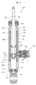
- FIG. 1 is a vertical sectional view of a shock absorber according to the present invention;
- FIG. 13 is an enlarged view of a side surface of a large diameter portion of a molded coil in a comparative example of the present invention.
- FIG. 9 is a vertical cross-sectional view of a shock absorber 100 according to the present invention. Note that in this embodiment, a shock absorber with adjustable damping force 100 will be used as an example.
- the damping force adjustable hydraulic shock absorber (hereinafter referred to as the shock absorber) 100 has a double cylinder structure with an outer cylinder 103 provided on the outside of a cylinder 102, and a reservoir 104 is formed between the cylinder 102 and the outer cylinder 103.
- a piston 105 is slidably fitted in the cylinder 102, and the inside of the cylinder 102 is divided into two chambers, a cylinder upper chamber 102A and a cylinder lower chamber 102B, by this piston 105.
- One end of a piston rod 106 is connected to the piston 105 by a nut 107, and the other end of the piston rod 106 passes through the cylinder upper chamber 102A, is inserted into a rod guide 108 and an oil seal 109 attached to the upper end of the cylinder 102 and the outer cylinder 103, and is extended to the outside of the cylinder 102.
- a base valve 110 is provided at the lower end of the cylinder 102 to separate the cylinder lower chamber 102B from the reservoir 104.
- the piston 105 is provided with oil passages 111 and 112 that connect the upper and lower cylinder chambers 102A and 102B.
- the oil passage 111 is provided with a check valve 113 that only allows oil to flow from the lower cylinder chamber 102B to the upper cylinder chamber 102A
- the oil passage 112 is provided with a disk valve 114 that opens when the pressure of the oil in the upper cylinder chamber 102A reaches a predetermined pressure, relieving the oil in the upper cylinder chamber 102A to the lower cylinder chamber 102B.
- the base valve 110 has oil passages 115 and 116 that connect the cylinder lower chamber 102B and the reservoir 104.
- the oil passage 115 has a check valve 117 that only allows oil to flow from the reservoir 104 to the cylinder lower chamber 102B, and the oil passage 116 has a disk valve 118 that opens when the pressure of the oil in the cylinder lower chamber 102B reaches a predetermined pressure, relieving the oil in the cylinder lower chamber 102B to the reservoir 104.
- the oil is sealed in the cylinder 102, and the oil and gas are sealed in the reservoir 104.
- Separator tubes 120 are fitted to the upper and lower ends of the cylinder 102 via seal members 119, and an annular oil passage 121 is formed between the cylinder 102 and the separator tube 120.
- the annular oil passage 121 is connected to the cylinder upper chamber 102A by an oil passage 122 provided in the side wall near the upper end of the cylinder 102.
- a small diameter opening 123 is provided in the side wall of the separator tube 120, and a large diameter opening 124 is provided in the side wall of the outer cylinder 103 approximately concentric with the opening 123, and a damping force generating mechanism 125 is attached to the opening 124 in the side wall of the outer cylinder 103.
- the damping force adjustable shock absorber 100 is mounted, for example, on an automobile suspension device.
- the damping force adjustable shock absorber 100 comprises a cylinder 102 filled with oil, a piston 105 connected to a piston rod 106 which is slidably fitted inside the cylinder 102 to divide the cylinder 102 into two chambers, and the flow of oil caused by the sliding of the piston 105 inside the cylinder 102 is controlled by a damping force generating mechanism 125 consisting of an orifice, a disk valve, etc. to generate a damping force, and a pressure control valve 128 is used to change the flow resistance of the damping force generating mechanism 125 to adjust the damping force.
- the damping force generating mechanism 125 comprises a solenoid 1 for controlling the pressure control valve 128, and constitutes an electromagnetic valve.
- the damping force generating mechanism 125 will be referred to as an "electromagnetic valve.”
- FIG. 1 is a vertical cross-sectional view of a solenoid 1 according to an embodiment of the present invention.
- the "axial direction” refers to the direction along the central axis 20a of the bobbin 20
- the radial direction refers to the radial direction of the bobbin 20, i.e., the direction perpendicular to the central axis 20a.
- the bobbin 20 has a tubular portion (cylindrical portion) 201 (see FIG. 2) as described below, and the central axis 20a is an axis passing through the center of the cylindrical portion 201.
- the solenoid 1 is used to open and close the pressure control valve 128 of the damping force adjustable shock absorber 100 that is mounted on the suspension device of a vehicle such as an automobile.
- the solenoid 1 comprises a molded coil 2, a yoke 3, a housing 4, a cylinder 5, an armature 6, an anchor 7, a rod 8, and a bush 9. 10 is a plate provided at one end of the solenoid 1.
- the rod 8 is fixed to the center of the armature 6, and the rod 8 is supported by the anchor 7 via the bush 9 so that it can move linearly in the axial direction.
- the rod 8 applies thrust to the valve body of the pressure control valve 128.
- FIG. 2 is a vertical cross-sectional view showing the molded coil 2 taken out from the solenoid 1 of FIG.
- the molded coil 2 has a bobbin 20 consisting of a cylindrical portion 201 and a large diameter portion 202 extending radially outward from the cylindrical portion 201, a coil 21 with an insulating coating wound around the cylindrical portion 201 of the bobbin 20, and a primary exterior body 22 that covers the outer periphery of the coil 21 and a side surface 202a of the large diameter portion 202 of the bobbin 20.
- a seal portion 23 is formed between the primary exterior body 22 and the large diameter portion 202 of the bobbin 20, and the seal portion 23 is located on the side surface 202a of the large diameter portion 202.
- the primary exterior body 22 is formed by overmolding the bobbin 20 around which the coil 21 is wound, and the seal portion 23 is formed by melting the interface between the primary exterior body 22 and the bobbin 20.
- end surface refers to the end surface in the axial direction.
- the axial position of end face 221 of primary outer casing 22 differs from the axial position of end face 2022 opposite end face 2021 connected to tubular portion 201 of large diameter portion 202, and distance L1 between end face 221 of primary outer casing 22 and end face 2021 of large diameter portion 202 is greater than thickness T1 of large diameter portion 202. That is, end face 221 of primary outer casing 22 is located in an axial direction away from end face 2022 of large diameter portion 202 on the opposite side to coil 21. In this case, height H1 of seal portion 23 in the axial direction is equal to thickness T1 of large diameter portion 202.
- the end face 2022 of the large diameter portion 202 is exposed over its entire surface.
- “exposed” means that it is not covered by the primary exterior body 22, but is exposed from the primary exterior body 22.
- the end face 2022 may be covered by the yoke 3 or the plate 10, as shown in FIG. 1.
- FIG. 4 is a diagram showing a modified example (first modified example) of the solenoid 1 according to the present invention, and is an enlarged view of the vicinity of the large diameter portion side surface 202a of the molded coil 2.
- the axial position of end face 221 of primary outer casing 22 coincides with the axial position of end face 2022 of large diameter portion 202.
- height H1 of seal portion 23 in the axial direction of bobbin 20 is equal to thickness T1 of large diameter portion 202.
- the axial length of molded coil 2 alone can be shortened compared to the case of Fig. 3, and the axial length of solenoid 1 can be reliably shortened.
- FIG. 5 is a diagram showing a modified example (second modified example) of the solenoid 1 according to the present invention, and is an enlarged view of the vicinity of the large diameter portion side surface 202a of the molded coil 2.
- the distance L1 between the end face 221 of the primary outer casing 22 and the end face 2021 of the large diameter portion 202 is smaller than the thickness T1 of the large diameter portion 202.
- the distance L1 between the end face 221 and the end face 2021 becomes the height H1 of the seal portion 23 in the axial direction, and the height H1 of the seal portion 23 is smaller than the thickness T1 of the large diameter portion 202. If the sealing performance of the seal portion 23 can be ensured, the distance L1 can be made smaller than the thickness T1, and the molded coil 2 can be made smaller in size.
- the side surface 202a of the large diameter portion 202 of the bobbin 20 is shown to have a simple cylindrical shape, but the side surface 202a of the large diameter portion 202 does not necessarily have to be cylindrical.
- the side surface 202a of the large diameter portion 202 may have an irregular shape, such as a protrusion portion.
- the height H1 of the seal portion 23 in the axial direction is equal to or smaller than the thickness T1 of the large diameter portion 202.
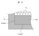
- FIG. 10 is an enlarged view of the large diameter portion side surface 202a of a molded coil in a comparative example to the present invention.
- the seal portion 23 between the primary exterior body 22 and the bobbin 20 is located on the side surface 202a of the large diameter portion 202.
- the primary exterior body 22 is also provided on the end surface 2022 of the large diameter portion, and the seal portion 23 is formed on the end surface 2022 of the large diameter portion 202 of the bobbin as well as on the side surface 202a of the large diameter portion 202 of the bobbin. Therefore, the area of the seal portion 23 is larger than that of this embodiment.
- the molding temperature during overmolding of the primary exterior body 22 is made higher than in the past, and the heat from the primary exterior body 22 reliably melts the resin material on the side surface 202a of the large diameter portion 202.
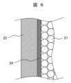
- FIG. 6 is an enlarged view of the outer periphery of the molded coil 2.
- a protective means 24 is provided between the primary exterior body 22 and the coil 21.
- the protective means 24 is, for example, a sheet-like member.
- the protective means will be referred to as a protective member or a protective section. If the molding temperature during overmolding of the primary exterior body 22 is set lower than the melting point of the protective section 24, the protective section 24 will not liquefy during injection molding, and direct contact between the primary exterior body 22 and the coil 21 can be avoided. For this reason, a material with a melting point higher than the heat resistance temperature of the insulating coating of the coil 21 is used for the protective section 24.
- the heat resistance temperature of the insulating coating of the coil 21 is the temperature at which the insulating performance of the coil 21 deteriorates after the primary exterior body 22 is overmolded, and is equal to or lower than the melting point of the insulating coating of the coil 21 .
- the molding temperature of the primary outer casing 22 can be set to or above the heat resistance temperature of the insulating coating of the coil 21, and the primary outer casing 22 can be molded at a higher temperature than conventionally possible.
- the protective part 24 it is preferable to use a material for the protective part 24 that has a lower thermal conductivity than the insulating coating of the coil 21. This makes it possible to reduce the amount of heat that transfers to the coil 21 through the protective part 24 during the injection molding of the primary exterior body 22.
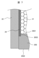
- FIG. 7 is an enlarged view of the vicinity of the outer periphery of the large diameter portion 202 of the bobbin 20.
- the diameter of the large diameter portion 202 is small, and a step (step portion) 2023 is formed in the large diameter portion 202. If there is a gap between the protective portion 24 and the large diameter portion 202, there is a risk that molten resin will flow into the outer periphery of the coil 21 during molding of the primary outer casing 22, damaging the insulating coating of the coil 21.
- the step 2023 it becomes easier to position the protective portion 24 so that the protective portion 24 reliably covers the axial end of the winding range of the coil 21 when winding the protective portion 24 around the outer periphery of the coil 21, and it is possible to prevent a gap from being generated between the end face 2021 of the large diameter portion 202 and the protective portion 24.
- the large diameter portion 202 has the step 2023 at the end face 2021 on the winding side of the coil 21, and the protective portion 24 is provided so as to cover the step 2023.
- the protective portion 24 is wound around the small diameter portion of the step 2023, so the seal portion 23 is not formed at the step 2023. Therefore, in order to prevent a decrease in the waterproof function of the seal portion 23, it is desirable to minimize the height of the step 2023. Also, it is not always necessary to provide the step 2023; for example, if the protective portion 24 is wound around the outer periphery of the coil 21 using a device with high positioning accuracy, the step 2023 does not always need to be provided.
- a sheet-like member is used as the protective portion 24, but other protective means, such as a sprayed coating agent or an overmolded resin layer, may also be used.
- the protective portion 24 is used, but in the case of a material with a small heat of fusion, such as syndiotactic polystyrene resin (SPS), the sealing portion 23 can have a sufficient waterproof function even if the molding temperature of the primary outer casing 22 is below the heat resistance temperature of the insulating coating of the coil 21, so the protective portion 24 does not need to be provided.
- SPS syndiotactic polystyrene resin
- the temperature during molding was determined by finite element analysis when a 0.3 mm thick fluororesin sheet (thermal conductivity 0.25 W.m -1 .K -1 ) was wound as the protective part 24 around the outermost periphery of the bobbin 20 having a 12.5 mm high cylindrical part 201.
- the cylinder temperature was set to 295°C, and the temperature when the primary exterior body 22 reached the large diameter part 202 was 280°C or higher and 295°C or lower, thereby ensuring the waterproof performance of the seal part 23.
- the melting point of the fluororesin sheet is 312°C, the protective part 24 does not melt during injection molding, and the insulating coating of the coil 21 (heat-resistant temperature 290°C to 300°C) is not damaged.
- the manufacturing method of the solenoid 1 of this embodiment is to provide a protective portion 24 on the outer circumferential surface of the coil 21, the protective portion 24 having a melting point higher than the heat resistance temperature of the insulating coating of the coil 21, heat the primary exterior body 22 to 280°C or higher, and then injection mold the primary exterior body 22 so that the outer circumferential surface of the primary exterior body 22 and the side surface 202a of the large diameter portion 202 of the bobbin 20 are covered and the end surface 2022 of the large diameter portion 202 is exposed.
- FIG. 8 is an example of a vertical cross-sectional view of a molding die 30 for the primary exterior body 22 .
- the molding die 30 has restraining portions 301 on both axial ends, which restrict the flow of the primary exterior body 22 in the axial direction Ax during injection molding.
- the protective portion 24 is provided on the outer periphery of the bobbin 20 around which the coil 21 is wound before the injection molding of the primary exterior body 22. Then, after the bobbin 20, the coil 21, and the protective portion 24 are placed inside the molding die 30, the primary exterior body 22 is injected through the gate 302 to fill the inside of the molding die 30.
- FIG. 8 shows an example in which the gate 302 is provided at one location on the molding die 30, and it is desirable to place the gate 302 at half the height of the tubular portion 201 so that the time it takes for the resin forming the primary exterior body 22 to reach the two large diameter portions 202 in the axial direction Ax during injection molding is minimized.
- the heating temperature in the cylinder is set to 295°C or higher so that the temperature when the primary exterior body 22 reaches the large diameter portions 202 during injection molding is 280°C or higher.
- the gate 302 is provided at one location at half the height of the tubular portion 201 is shown, but the gate 302 does not necessarily have to be provided at half the height of the tubular portion 201, and multiple gates may be provided instead of one location.
- the seal portion 23 of the molded coil 2 is located on the side surface 202a of the large diameter portion 202 of the bobbin 20, so the end surface 2022 of the large diameter portion 202 is exposed. Therefore, the axial length of the molded coil 2 can be made shorter than that of the molded coil structure of the comparative example to the present invention shown in FIG. 10. This allows the axial length of the housing 4 and anchor 6 to be shortened, the axial length of the solenoid 1 to be shortened, and the solenoid valve 125 of the shock absorber 100 to be made smaller.
- the axial length of the tubular portion 201 of the bobbin 20 can be made longer than the molded coil structure of the comparative example of the present invention.
- the number of turns of the coil 21 can be increased, thereby increasing the attractive force of the armature 6 and anchor 7 and increasing the thrust of the solenoid 1.
- a solenoid 1 mounted on an electromagnetic valve 125, Solenoid 1 is a bobbin 20 having a cylindrical portion 201 and a large diameter portion 202 formed at one end of the cylindrical portion 201 and extending radially outward from the cylindrical portion 201; A coil 21 wound around a cylindrical portion 201 of a bobbin 20; a primary exterior body 22 that covers an outer periphery of the coil 21 and a side surface 202 a of the large diameter portion 202 of the bobbin 20 and forms a seal portion 23 between the primary exterior body 22 and the side surface 202 a of the large diameter portion 202 of the bobbin 20; having Of both end faces 2021 , 2022 of large diameter portion 202 , end face 2022 opposite the side on which coil 21 is wound is at least partially exposed from primary exterior body 22 .
- the height H1 of the seal portion 23 in the axial direction of the bobbin 20 is equal to or smaller than the thickness T1 of the large diameter portion 202.
- a protective portion 24 is provided between the outer circumferential surface of the coil 21 and the primary outer casing 22, The melting point of the protective portion 24 is higher than the heat-resistant temperature of the insulating coating of the coil 21 .
- the thermal conductivity of the protective portion 24 is less than that of the insulating coating of the coil 21.
- a protective portion 24 is provided between the outer circumferential surface of the coil 21 and the primary outer casing 22,
- the protective portion 24 is made of a sheet-like member.
- the large diameter portion 202 has a step 2023 on the end surface 2021 on the winding side of the coil 21,
- the protective portion 24 is provided to cover the step 2023 .
- a shock absorber 100 that is mounted on a suspension device of an automobile and has a pressure control valve 128 and a solenoid for controlling the pressure control valve 128,
- the solenoid includes a solenoid 1.
- a method for manufacturing a solenoid 1, comprising the steps of: A protective portion 24 having a melting point higher than the heat resistance temperature of the insulating coating of the coil 21 is provided on the outer circumferential surface of the coil 21, The primary exterior body 22 is heated to 280° C. or higher. The primary exterior body 22 is injection molded so as to cover the outer peripheral surface of the primary exterior body 22 and the side surface 202a of the large diameter portion 202 of the bobbin 20 and to expose the end surface 2022 of the large diameter portion 202.
- the protective portion 22 has a lower thermal conductivity than the insulating coating of the coil 21 .
- the present invention is not limited to the above-mentioned examples, and other forms that are conceivable within the scope of the technical concept of the present invention are also included within the scope of the present invention, so long as they do not impair the characteristics of the present invention. Furthermore, the present invention is not limited to the above-mentioned examples, and includes various modified examples. For example, the above-mentioned examples have been described in detail to clearly explain the present invention, and are not necessarily limited to those that include all of the configurations. Furthermore, it is possible to add, delete, or replace part of the configuration of the examples with other configurations.
Landscapes
- Engineering & Computer Science (AREA)
- General Engineering & Computer Science (AREA)
- Physics & Mathematics (AREA)
- Electromagnetism (AREA)
- Mechanical Engineering (AREA)
- Power Engineering (AREA)
- Electromagnets (AREA)
- Magnetically Actuated Valves (AREA)
- Fluid-Damping Devices (AREA)
Abstract
Description
電磁弁に搭載されるソレノイドであって、
前記ソレノイドは、
筒部と、前記筒部の一端に形成され前記筒部の径方向外方に向けて延びる大径部と、を有するボビンと、
前記ボビンの前記筒部に巻回されたコイルと、
前記コイルの外周と前記ボビンの前記大径部の側面とを被覆し前記ボビンの前記大径部の側面との間でシール部を構成する1次外装体と、
を有し、
前記大径部の両端面のうち前記コイルの巻回側とは反対側の端面は、少なくとも一部が前記1次外装体から露出している。
上記した以外の課題、構成および効果は、以下の発明を実施するための形態の説明により明らかにされる。
<ソレノイド1の構造>
図1は、本発明の一実施例に係るソレノイド1の縦断面図である。
以下の説明において、「軸方向」はボビン20の中心軸線20aに沿う方向であり、径方向はボビン20の径方向、すなわち中心軸線20aに直交する方向である。ボビン20は、後述するように筒部(円筒部)201(図2参照)を有しており、中心軸線20aは円筒部201の中心を通る軸線である。
図2は、図1のソレノイド1からモールドコイル2を取り出して示す縦断面図である。
モールドコイル2は、筒部201と筒部201から径方向外方に向けて延びる大径部202とからなるボビン20と、ボビン20の筒部201に巻回された絶縁被覆付きのコイル21と、コイル21の外周とボビン20の大径部202の側面202aとを被覆する1次外装体22と、を有する。1次外装体22とボビン20の大径部202との間でシール部23が構成されており、シール部23は大径部202の側面202aに位置する。1次外装体22は、コイル21が巻回されたボビン20をオーバーモールドして形成され、シール部23は1次外装体22とボビン20との界面が溶融して形成されるものである。
1次外装体22の端面221の軸方向位置は、大径部202の筒部201とつながっている端面2021と反対側の端面2022の軸方向位置と異なり、1次外装体22の端面221と大径部202の端面2021との距離L1は大径部202の厚みT1よりも大きい。すなわち1次外装体22の端面221は、軸方向において、大径部202の端面2022に対してコイル21側とは反対側に外れた位置にある。この場合、軸方向におけるシール部23の高さH1は、大径部202の厚さT1と等しい。
本例では、1次外装体22の端面221の軸方向位置は大径部202の端面2022の軸方向位置と一致する。この場合、ボビン20の軸方向におけるシール部23の高さH1は、大径部202の厚さT1と等しい。本例は、図3の場合と比べて、モールドコイル2単体での軸方向長さを短くでき、ソレノイド1の軸方向長さを確実に短くできる。
本例では、1次外装体22の端面221と大径部202の端面2021との距離L1は大径部202の厚みT1よりも小さい。この場合、端面221と端面2021との距離L1が軸方向におけるシール部23の高さH1となり、シール部23の高さH1は大径部202の厚さT1よりも小さい。シール部23でのシール性能を確保できる場合、距離L1を厚みT1よりも小さくすることができ、モールドコイル2を小型化することができる。
図10は、本発明との比較例におけるモールドコイルの大径部側面202aの拡大図である。
本実施例において、1次外装体22とボビン20とのシール部23は大径部202の側面202aに位置している。一方、本発明との比較例では、図10に示すように、1次外装体22は大径部の端面2022にも設けられ、シール部23はボビンの大径部202の側面202aのほか、大径部の端面2022にも構成される。このため、シール部23の面積は本実施例より大きい。
1次外装体22とコイル21との間に保護手段24が設けられている。保護手段24は、例えばシート状の部材を用いる。以下、保護手段は保護部材または保護部と呼んで説明する。1次外装体22のオーバーモールド時の成形温度を保護部24の融点よりも低く設定すると、射出成形時に保護部24が液化することはないため、1次外装体22とコイル21との直接接触は避けられる。そのため、保護部24として、融点がコイル21の絶縁被膜の耐熱温度よりも高い材料を用いる。
1次外装体22とコイル21との間に保護部24を設けることにより、1次外装体22の成形温度をコイル21の絶縁被膜の耐熱温度以上に設定でき、従来よりも高い温度で1次外装体22をモールド成形することができる。
モールドコイル2の大径部202の端面2021において、大径部202の直径は小さくなっており、大径部202に段差(段差部)2023が形成されている。保護部24と大径部202との間に隙間がある場合、1次外装体22の成形中に溶融樹脂がコイル21の外周部に流れ込み、コイル21の絶縁被膜を損傷させるリスクがある。しかし、段差2023を設けることにより、保護部24をコイル21の外周部に巻き付ける際に、保護部24がコイル21の巻回範囲の軸方向端部を確実に覆うように保護部24を位置決めすることが容易になり、大径部202の端面2021と保護部24との間に隙間が生じることを防ぐことができる。この場合、大径部202は、コイル21の巻回側の端面2021に段差2023を有し、保護部24は段差2023を覆うように設けられる。
ガラス繊維強化ナイロン樹脂(PA66-GF30)を用いて、本実施例におけるシール部23の防水性能を検証した。直径28mm、厚さ3mmの大径部を有するボビン20を対象に、1次外装体22がボビン20の大径部202に到達した時に280℃以上になるように、ボビン20の大径部202の側面付近にゲートを設置してボビン20のオーバーモールドを行った。そして、得られたモールドコイル2の水没試験により漏れの有無を確認した。その結果、漏れは大径部側面202aの厚さ1mmの部分で遮断されており、1次外装体20とボビン20とのシール部を大径部側面202aにのみ設けても、必要な防水機能が確保されることを確認した。
次にソレノイド1のモールドコイル2の製造プロセスの例を示す。なお、本実施例では、ガラス繊維強化ナイロン樹脂(例えば、PA66-GF30)の例を示す。
成形金型30は、軸方向の両端に拘束部301を備え、射出成型時に1次外装体22の軸方向Axへの流動を規制している。
以上説明した実施例およびその変更例によれば、次の作用効果が得られる。
(1)電磁弁125に搭載されるソレノイド1であって、
ソレノイド1は、
筒部201と、筒部201の一端に形成され筒部201の径方向外方に向けて延びる大径部202と、を有するボビン20と、
ボビン20の筒部201に巻回されたコイル21と、
コイル21の外周とボビン20の大径部202の側面202aとを被覆しボビン20の大径部202の側面202aとの間でシール部23を構成する1次外装体22と、
を有し、
大径部202の両端面2021,2022のうちコイル21の巻回側とは反対側の端面2022は、少なくとも一部が1次外装体22から露出している。
保護部24は、融点がコイル21の絶縁被膜の耐熱温度よりも高い。
保護部24は、シート状の部材で構成される。
保護部24は、段差2023を覆うように設けられる。
ソレノイドとしてソレノイド1を備える。
コイル21の外周面に、融点がコイル21の絶縁被膜の耐熱温度よりも高い保護部24を設け、
1次外装体22を280℃以上に加熱し、
1次外装体22の外周面とボビン20の大径部202の側面202aを被覆し、大径部202の端面2022が露出するように、1次外装体22を射出成形する。
保護部22は、熱伝導率がコイル21の絶縁被膜の熱伝導率よりも小さい。
Claims (10)
- 電磁弁に搭載されるソレノイドであって、
前記ソレノイドは、
筒部と、前記筒部の一端に形成され前記筒部の径方向外方に向けて延びる大径部と、を有するボビンと、
前記ボビンの前記筒部に巻回されたコイルと、
前記コイルの外周と前記ボビンの前記大径部の側面とを被覆し前記ボビンの前記大径部の側面との間でシール部を構成する1次外装体と、
を有し、
前記大径部の両端面のうち前記コイルの巻回側とは反対側の端面は、少なくとも一部が前記1次外装体から露出しているソレノイド。 - 請求項1に記載のソレノイドであって、
前記ボビンの軸方向における前記シール部の高さは、前記大径部の厚さと等しいか前記大径部の厚さよりも小さいソレノイド。 - 請求項1に記載のソレノイドであって、
前記大径部の両端面のうち前記コイルの巻回側とは反対側の端面は、全体が前記1次外装体から露出しているソレノイド。 - 請求項1に記載のソレノイドであって、
前記コイルの外周面と前記1次外装体との間に保護部を有し、
前記保護部は、融点が前記コイルの絶縁被膜の耐熱温度よりも高いソレノイド。 - 請求項4に記載のソレノイドであって、
前記保護部は、熱伝導率が前記絶縁被膜の熱伝導率よりも小さいソレノイド。 - 請求項1に記載のソレノイドであって、
前記コイルの外周面と前記1次外装体との間に保護部を有し、
前記保護部は、シート状の部材で構成されるソレノイド。 - 請求項6に記載のソレノイドであって、
前記大径部は、前記コイルの巻回側の端面に段差を有し、
前記保護部は、前記段差を覆うように設けられているソレノイド。 - 自動車のサスペンション装置に装着され、圧力制御弁と、前記圧力制御弁を制御するためのソレノイドとを有する緩衝器であって、
前記ソレノイドとして請求項1に記載のソレノイドを備えた緩衝器。 - 請求項1に記載のソレノイドの製造方法であって、
前記コイルの外周面に、融点が前記コイルの絶縁被膜の耐熱温度よりも高い保護部を設け、
前記1次外装体を280℃以上に加熱し、
前記1次外装体の外周面と前記ボビンの前記大径部の側面を被覆し、前記大径部の端面が露出するように、前記1次外装体を射出成形するソレノイドの製造方法。 - 請求項9に記載のソレノイドの製造方法であって、
前記保護部は、熱伝導率が前記絶縁被膜の熱伝導率よりも小さいソレノイドの製造方法。
Priority Applications (3)
| Application Number | Priority Date | Filing Date | Title |
|---|---|---|---|
| DE112024000376.1T DE112024000376T5 (de) | 2023-06-30 | 2024-05-14 | Solenoid, stossdämpfer und verfahren zur herstellung eines solenoids |
| KR1020257025731A KR20250130391A (ko) | 2023-06-30 | 2024-05-14 | 솔레노이드, 완충기 및 솔레노이드의 제조 방법 |
| CN202480009721.0A CN120660157A (zh) | 2023-06-30 | 2024-05-14 | 螺线管、缓冲器及螺线管的制造方法 |
Applications Claiming Priority (2)
| Application Number | Priority Date | Filing Date | Title |
|---|---|---|---|
| JP2023107732A JP2025006750A (ja) | 2023-06-30 | 2023-06-30 | ソレノイド、緩衝器及びソレノイドの製造方法 |
| JP2023-107732 | 2023-06-30 |
Publications (1)
| Publication Number | Publication Date |
|---|---|
| WO2025004566A1 true WO2025004566A1 (ja) | 2025-01-02 |
Family
ID=93938109
Family Applications (1)
| Application Number | Title | Priority Date | Filing Date |
|---|---|---|---|
| PCT/JP2024/017721 Ceased WO2025004566A1 (ja) | 2023-06-30 | 2024-05-14 | ソレノイド、緩衝器及びソレノイドの製造方法 |
Country Status (5)
| Country | Link |
|---|---|
| JP (1) | JP2025006750A (ja) |
| KR (1) | KR20250130391A (ja) |
| CN (1) | CN120660157A (ja) |
| DE (1) | DE112024000376T5 (ja) |
| WO (1) | WO2025004566A1 (ja) |
Citations (3)
| Publication number | Priority date | Publication date | Assignee | Title |
|---|---|---|---|---|
| JPH0550703U (ja) * | 1991-12-03 | 1993-07-02 | 日信工業株式会社 | 電磁コイル |
| JP2017089763A (ja) * | 2015-11-11 | 2017-05-25 | 住友電装株式会社 | ソレノイドバルブ及びソレノイドバルブの製造方法 |
| WO2021117800A1 (ja) * | 2019-12-12 | 2021-06-17 | 日立Astemo株式会社 | ソレノイド、減衰力調整機構および減衰力調整式緩衝器 |
Family Cites Families (1)
| Publication number | Priority date | Publication date | Assignee | Title |
|---|---|---|---|---|
| JPH0963835A (ja) | 1995-08-24 | 1997-03-07 | Tokimec Inc | モールドコイル |
-
2023
- 2023-06-30 JP JP2023107732A patent/JP2025006750A/ja active Pending
-
2024
- 2024-05-14 CN CN202480009721.0A patent/CN120660157A/zh active Pending
- 2024-05-14 WO PCT/JP2024/017721 patent/WO2025004566A1/ja not_active Ceased
- 2024-05-14 DE DE112024000376.1T patent/DE112024000376T5/de active Pending
- 2024-05-14 KR KR1020257025731A patent/KR20250130391A/ko active Pending
Patent Citations (3)
| Publication number | Priority date | Publication date | Assignee | Title |
|---|---|---|---|---|
| JPH0550703U (ja) * | 1991-12-03 | 1993-07-02 | 日信工業株式会社 | 電磁コイル |
| JP2017089763A (ja) * | 2015-11-11 | 2017-05-25 | 住友電装株式会社 | ソレノイドバルブ及びソレノイドバルブの製造方法 |
| WO2021117800A1 (ja) * | 2019-12-12 | 2021-06-17 | 日立Astemo株式会社 | ソレノイド、減衰力調整機構および減衰力調整式緩衝器 |
Also Published As
| Publication number | Publication date |
|---|---|
| KR20250130391A (ko) | 2025-09-01 |
| JP2025006750A (ja) | 2025-01-17 |
| CN120660157A (zh) | 2025-09-16 |
| DE112024000376T5 (de) | 2025-10-09 |
Similar Documents
| Publication | Publication Date | Title |
|---|---|---|
| CN100575766C (zh) | 压力容器的制造方法 | |
| CN103807071B (zh) | 直喷式燃料喷射阀的支承结构 | |
| JP7217756B2 (ja) | 減衰力調整式緩衝器およびソレノイド | |
| JP6877286B2 (ja) | 減衰力調整式緩衝器及びその製造方法 | |
| KR101497655B1 (ko) | 서모스탯용 카트리지 히터 및 그 제작방법 | |
| CN114787947A (zh) | 螺线管、衰减力调整机构以及衰减力调整式缓冲器 | |
| JP4996558B2 (ja) | 可変減衰力ダンパ | |
| JP2006528311A (ja) | 騒音を減衰する減衰円板を有する電磁弁 | |
| JP6049903B2 (ja) | 燃料噴射弁、及び燃料噴射弁の製造方法 | |
| JP2025006750A (ja) | ソレノイド、緩衝器及びソレノイドの製造方法 | |
| KR20230023018A (ko) | 솔레노이드, 솔레노이드 밸브, 완충기 및 솔레노이드의 제조 방법 | |
| JP4027428B2 (ja) | 点火装置のための棒状コイル | |
| US12044311B2 (en) | Locking unit | |
| WO2016147317A1 (ja) | 高圧ガス容器及び高圧ガス容器の製造方法 | |
| KR20130105832A (ko) | 연료분사밸브 | |
| US6003792A (en) | Cylinder injection type fuel injection valve | |
| JP2019173786A (ja) | 緩衝器 | |
| JP2006329272A (ja) | 弁装置 | |
| CN102700050B (zh) | 磁流变减振器的电磁线圈组件注塑加工工艺 | |
| JP7377958B2 (ja) | ソレノイド、減衰力調整機構および減衰力調整式緩衝器 | |
| US10738747B2 (en) | Injector | |
| WO2026053521A1 (ja) | ソレノイド | |
| JP5009580B2 (ja) | 内燃機関ための点火コイル | |
| US5095234A (en) | Electromagnetic solenoid | |
| JP2005209853A (ja) | コイル装置の製造方法 |
Legal Events
| Date | Code | Title | Description |
|---|---|---|---|
| 121 | Ep: the epo has been informed by wipo that ep was designated in this application |
Ref document number: 24831439 Country of ref document: EP Kind code of ref document: A1 |
|
| WWE | Wipo information: entry into national phase |
Ref document number: 202480009721.0 Country of ref document: CN |
|
| ENP | Entry into the national phase |
Ref document number: 1020257025731 Country of ref document: KR Free format text: ST27 STATUS EVENT CODE: A-0-1-A10-A15-NAP-PA0105 (AS PROVIDED BY THE NATIONAL OFFICE) |
|
| WWE | Wipo information: entry into national phase |
Ref document number: 112024000376 Country of ref document: DE |
|
| WWP | Wipo information: published in national office |
Ref document number: 202480009721.0 Country of ref document: CN |
|
| WWP | Wipo information: published in national office |
Ref document number: 112024000376 Country of ref document: DE |
|
| 122 | Ep: pct application non-entry in european phase |
Ref document number: 24831439 Country of ref document: EP Kind code of ref document: A1 |