WO2025004539A1 - ガスタービン発電プラント、及びその運転方法 - Google Patents
ガスタービン発電プラント、及びその運転方法 Download PDFInfo
- Publication number
- WO2025004539A1 WO2025004539A1 PCT/JP2024/017029 JP2024017029W WO2025004539A1 WO 2025004539 A1 WO2025004539 A1 WO 2025004539A1 JP 2024017029 W JP2024017029 W JP 2024017029W WO 2025004539 A1 WO2025004539 A1 WO 2025004539A1
- Authority
- WO
- WIPO (PCT)
- Prior art keywords
- gas turbine
- power plant
- output
- turbine power
- storage battery
- Prior art date
- Legal status (The legal status is an assumption and is not a legal conclusion. Google has not performed a legal analysis and makes no representation as to the accuracy of the status listed.)
- Ceased
Links
Images

Classifications
-
- B—PERFORMING OPERATIONS; TRANSPORTING
- B01—PHYSICAL OR CHEMICAL PROCESSES OR APPARATUS IN GENERAL
- B01D—SEPARATION
- B01D53/00—Separation of gases or vapours; Recovering vapours of volatile solvents from gases; Chemical or biological purification of waste gases, e.g. engine exhaust gases, smoke, fumes, flue gases, aerosols
- B01D53/34—Chemical or biological purification of waste gases
- B01D53/46—Removing components of defined structure
- B01D53/62—Carbon oxides
-
- F—MECHANICAL ENGINEERING; LIGHTING; HEATING; WEAPONS; BLASTING
- F01—MACHINES OR ENGINES IN GENERAL; ENGINE PLANTS IN GENERAL; STEAM ENGINES
- F01K—STEAM ENGINE PLANTS; STEAM ACCUMULATORS; ENGINE PLANTS NOT OTHERWISE PROVIDED FOR; ENGINES USING SPECIAL WORKING FLUIDS OR CYCLES
- F01K23/00—Plants characterised by more than one engine delivering power external to the plant, the engines being driven by different fluids
-
- F—MECHANICAL ENGINEERING; LIGHTING; HEATING; WEAPONS; BLASTING
- F02—COMBUSTION ENGINES; HOT-GAS OR COMBUSTION-PRODUCT ENGINE PLANTS
- F02C—GAS-TURBINE PLANTS; AIR INTAKES FOR JET-PROPULSION PLANTS; CONTROLLING FUEL SUPPLY IN AIR-BREATHING JET-PROPULSION PLANTS
- F02C1/00—Gas-turbine plants characterised by the use of hot gases or unheated pressurised gases, as the working fluid
- F02C1/02—Gas-turbine plants characterised by the use of hot gases or unheated pressurised gases, as the working fluid the working fluid being an unheated pressurised gas
-
- F—MECHANICAL ENGINEERING; LIGHTING; HEATING; WEAPONS; BLASTING
- F02—COMBUSTION ENGINES; HOT-GAS OR COMBUSTION-PRODUCT ENGINE PLANTS
- F02C—GAS-TURBINE PLANTS; AIR INTAKES FOR JET-PROPULSION PLANTS; CONTROLLING FUEL SUPPLY IN AIR-BREATHING JET-PROPULSION PLANTS
- F02C6/00—Plural gas-turbine plants; Combinations of gas-turbine plants with other apparatus; Adaptations of gas-turbine plants for special use
- F02C6/04—Gas-turbine plants providing heated or pressurised working fluid for other apparatus, e.g. without mechanical power output
- F02C6/06—Gas-turbine plants providing heated or pressurised working fluid for other apparatus, e.g. without mechanical power output providing compressed gas
- F02C6/08—Gas-turbine plants providing heated or pressurised working fluid for other apparatus, e.g. without mechanical power output providing compressed gas the gas being bled from the gas-turbine compressor
-
- F—MECHANICAL ENGINEERING; LIGHTING; HEATING; WEAPONS; BLASTING
- F02—COMBUSTION ENGINES; HOT-GAS OR COMBUSTION-PRODUCT ENGINE PLANTS
- F02C—GAS-TURBINE PLANTS; AIR INTAKES FOR JET-PROPULSION PLANTS; CONTROLLING FUEL SUPPLY IN AIR-BREATHING JET-PROPULSION PLANTS
- F02C9/00—Controlling gas-turbine plants; Controlling fuel supply in air- breathing jet-propulsion plants
- F02C9/48—Control of fuel supply conjointly with another control of the plant
- F02C9/50—Control of fuel supply conjointly with another control of the plant with control of working fluid flow
- F02C9/52—Control of fuel supply conjointly with another control of the plant with control of working fluid flow by bleeding or by-passing the working fluid
Definitions
- a gas turbine is equipped with a compressor that compresses air, a combustor that burns fuel in the air compressed by the compressor to generate combustion gas, and a turbine that is driven by the combustion gas.
- the rotor of the gas turbine is connected to the rotor of a generator.
- Patent Document 1 discloses a technology for dealing with a situation when the load on the power system decreases and the required output from the outside decreases. With this technology, when the required output from the outside decreases, some of the air compressed by the compressor is bled from the gas turbine to suppress the output of the gas turbine. The high-pressure air bled from the gas turbine is stored in an air tank and used as appropriate.
- the present disclosure therefore aims to provide technology that can flexibly respond to fluctuations in external required output.
- the bleed valve when the actual output of the gas turbine falls below a predetermined bleed output that is smaller than the rated output, the bleed valve is opened, and a portion of the compressed air generated by the compressor is bled outside the gas turbine as bleed air. Therefore, in this embodiment, when the actual output of the gas turbine falls from the rated output to the bleed output or less, and the flow rate of fuel supplied to the combustor decreases accordingly, the flow rate of compressed air supplied to the combustor also decreases, making it possible to suppress deterioration of fuel combustibility. Therefore, in this embodiment, it is possible to handle cases where the required output is below the bleed output and the actual output is set to below the bleed output, while suppressing deterioration of fuel combustibility.
- the auxiliary turbine is driven by the bleed air, and the auxiliary generator generates electricity by this drive.
- the electricity generated by the auxiliary generator is stored in the storage battery.
- the external power system in addition to the power from the gas turbine generator, can be supplied with power from the storage battery. Therefore, in this embodiment, it can be used even in cases where the required output from outside is greater than the rated output, and the gas turbine generator alone cannot handle the demand.
- this embodiment can flexibly respond to fluctuations in external required output.
- This gas turbine power plant includes a gas turbine having a compressor capable of compressing air, a combustor capable of burning fuel in the compressed air compressed by the compressor to generate combustion gas, and a turbine capable of being driven by the combustion gas, and a gas turbine generator connected to the gas turbine, generating electricity by driving the turbine, and capable of transmitting the electricity to an external power system.
- the method executes an extraction process of extracting a part of the compressed air generated by the compressor as extraction air to the outside of the gas turbine to reduce a flow rate of the compressed air flowing into the combustor, and a charging process of storing electricity in a storage battery that can be discharged to the external power system, wherein an auxiliary turbine is driven by the extraction air, an auxiliary generator is driven by the driving of the auxiliary turbine to generate electricity, and the electricity generated by the auxiliary generator is stored in the storage battery.
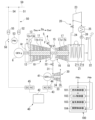
- FIG. 1 is a system diagram of a gas turbine power plant in a first embodiment according to the present disclosure.
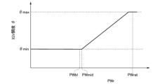
- 4 is a graph showing a relationship between an actual output and an IGV aperture of a gas turbine power plant in the first embodiment according to the present disclosure.
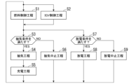
- 4 is a flowchart showing an operation of the gas turbine power plant in the first embodiment according to the present disclosure.
- FIG. 4 is a system diagram of a gas turbine power plant in a second embodiment according to the present disclosure.
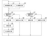
- 10 is a flowchart showing an operation of a gas turbine power plant in a second embodiment according to the present disclosure.
- FIG. 1 A first embodiment of gas turbine power plant
- FIG. 1 A first embodiment of a gas turbine power plant according to the present disclosure will be described with reference to FIGS. 1 to 3.
- FIG. 1 A first embodiment of a gas turbine power plant according to the present disclosure will be described with reference to FIGS. 1 to 3.
- FIG. 1 A first embodiment of a gas turbine power plant according to the present disclosure will be described with reference to FIGS. 1 to 3.
- FIG. 1 First embodiment of gas turbine power plant
- the gas turbine power plant in this embodiment includes a gas turbine 1, a waste heat utilization system 20 that utilizes the heat of the exhaust gas discharged from the gas turbine 1, a gas turbine generator 6 that generates electricity by driving the gas turbine 1, an air extraction system 30 that can extract part of the air inside the gas turbine 1 to the outside, an auxiliary power generation system 40, a power system system 50, and a control device 100.
- the gas turbine 1 includes a compressor 10 capable of compressing air A, a combustor 15 capable of generating combustion gas by burning fuel F in the compressed air compressed by the compressor 10, a fuel valve 5, a turbine 16 capable of being driven by the high-temperature, high-pressure combustion gas, and an intermediate casing 3.
- the compressor 10 has a compressor rotor 11 that rotates around the rotor axis Ar, a compressor casing 12 that covers the compressor rotor 11, and an intake air regulator 13.
- the direction in which the rotor axis Ar extends is referred to as the axial direction Da
- one of the two sides of this axial direction Da is referred to as the axial upstream side Dau
- the other is referred to as the axial downstream side Dad.
- the compressor rotor 11 has a compressor rotor shaft 11s extending in the axial direction Da centered on the rotor axis Ar, and a number of moving blade rows 11b fixed to the compressor rotor shaft 11s.
- the multiple moving blade rows 11b are aligned in the axial direction Da.
- Each of the multiple moving blade rows 11b has a number of moving blades aligned in the circumferential direction about the rotor axis Ar.
- the intake air regulator 13 has a number of inlet guide vanes (IGVs) 13v arranged inside the compressor casing 12 and axially upstream Dau of the multiple moving blade rows 11b, and a driver 13d that can change the orientation of each inlet guide vane 13v.
- IGVs inlet guide vanes
- the turbine 16 is disposed on the axial downstream side Dad of the compressor 10.
- This turbine 16 has a turbine rotor 17 that rotates around the rotor axis Ar by the combustion gas from the combustor 15, and a turbine casing 18 that covers this turbine rotor 17.
- the turbine rotor 17 has a turbine rotor shaft 17s that extends in the axial direction Da centered on the rotor axis Ar, and multiple moving blade rows 17b fixed to the turbine rotor shaft 17s.
- the multiple moving blade rows 17b are aligned in the axial direction Da.
- Each of the multiple moving blade rows 17b has multiple moving blades aligned in the circumferential direction relative to the rotor axis Ar.
- the turbine rotor 17 and the compressor rotor 11 are connected to each other so that they can rotate together about the same rotor axis Ar, forming the gas turbine rotor 2.
- the rotor of the gas turbine generator 6 is connected to this gas turbine rotor 2.
- the intermediate casing 3 is disposed between the compressor casing 12 and the turbine casing 18 in the axial direction Da, and connects the compressor casing 12 and the turbine casing 18. Compressed air discharged from the compressor 10 flows into the intermediate casing 3.
- the combustor 15 is fixed to the intermediate casing 3.
- a fuel line 4 is connected to the combustor 15.
- the fuel line 4 is provided with the aforementioned fuel valve 5 that adjusts the flow rate of the fuel F flowing through the fuel line 4.
- the waste heat utilization equipment 20 comprises a waste heat recovery boiler 21, a chimney 22, a steam turbine 23 driven by steam from the waste heat recovery boiler 21, a main steam line 24 capable of directing steam generated in the waste heat recovery boiler 21 to the steam turbine 23, a condenser 25 capable of converting steam exhausted from the steam turbine 23 back into water, a feed water line 26 capable of directing the water in the condenser 25 to the waste heat recovery boiler 21, and a feed water pump 27 provided in the feed water line 26.
- a driven object that can be rotated by the rotation of the rotor is connected to the rotor of the steam turbine 23. Examples of the driven object include the rotor of the gas turbine generator 6, the rotor of a ST generator independent of the gas turbine generator 6, and the impeller of a pump.
- the heat recovery boiler 21 can generate steam by evaporating water using the heat of the exhaust gas, which is the combustion gas discharged from the turbine 16.
- the heat recovery boiler 21 has a duct 21d connected to the turbine casing 18, and a heat transfer tube 21t arranged in the duct 21d. Exhaust gas from the turbine 16 flows in the duct 21d. Liquid water or gaseous water flows in the heat transfer tube 21t.
- One end of the heat transfer tube 21t forms a water inlet and is connected to the water supply line 26.
- the other end of the heat transfer tube 21t forms a steam outlet and is connected to the main steam line 24.
- the chimney 22 is connected to the duct 21d of the heat recovery boiler 21.
- the bleed air equipment 30 includes an bleed air line 31 that can bleed a portion of the compressed air generated by the compressor 10 from the gas turbine 1 as bleed air, an bleed air valve 32, and an auxiliary turbine 33 that can be driven by the bleed air that flows through the bleed air line 31.
- the auxiliary turbine 33 has a rotatable auxiliary turbine rotor 34 and an auxiliary turbine casing 35 that covers the auxiliary turbine rotor 34.
- One end of the bleed line 31 is connected to the intermediate casing 3 of the gas turbine 1.
- the other end of the bleed line 31 is connected to the auxiliary turbine casing 35.
- the auxiliary turbine rotor 34 rotates due to the bleed air that has flowed into the auxiliary turbine casing 35.
- the bleed valve 32 is provided in the bleed line 31. This bleed valve 32 can adjust the flow rate of the bleed air flowing through the bleed line 31.
- the auxiliary power generating equipment 40 includes an auxiliary generator 41, a storage battery 42, an auxiliary generator power line 43, an AC/DC converter 44 capable of converting AC power to DC power, and a DC/AC converter 45 capable of converting DC power to AC power.
- the rotor of the auxiliary generator 41 is connected to the auxiliary turbine rotor 34. Therefore, the auxiliary generator 41 generates power by driving the auxiliary turbine 33.
- the auxiliary generator power line 43 electrically connects the auxiliary generator 41 and the storage battery 42.
- the AC/DC converter 44 is provided in this auxiliary generator power line 43. Therefore, the AC power generated by the auxiliary generator 41 is converted to DC power by the AC/DC converter 44, and the electrical energy of this AC power is stored in the storage battery 42.
- the power system equipment 50 includes a gas turbine power line 51 that electrically connects the gas turbine generator 6 to an external power system 59, a transformer 52 provided on the gas turbine power line 51, a power meter 53, a storage battery power line 54 that electrically connects the storage battery 42 to the external power system 59, a transformer 55 provided on the storage battery power line 54, and a switch 56.
- the power meter 53 can detect the actual power generation amount of the gas turbine generator 6, in other words, the actual output that is the actual output of the gas turbine 1.
- the switch 56 is provided in the storage battery power line 54 between the transformer 55 and the storage battery 42.
- the switch 56 can realize an ON state in which the storage battery 42 and the external power system 59 are electrically connected, and an OFF state in which the storage battery 42 and the external power system 59 are not electrically connected.
- the DC/AC converter 45 described above is provided in the storage battery power line 54 between the switch 56 and the storage battery 42.
- the control device 100 has a fuel controller 101 capable of controlling the opening of the fuel valve 5, an IGV controller 102 capable of controlling the IGV opening ⁇ , which is the opening of the inlet guide vane 13v of the compressor 10, an air bleed controller 103 capable of controlling the opening of the air bleed valve 32, and an opening/closing controller 104 capable of controlling the state of the opening/closing switch 56.
- the fuel controller 101 receives the required power PWc required of the gas turbine 1 from the outside and the actual power PWr detected by the power meter 53, determines the opening of the fuel valve 5 according to the deviation between the required power PWc and the actual power PWr, and instructs the fuel valve 5 of this opening.
- the change in the flow rate of fuel supplied to the combustor 15 is positively correlated with the change in the opening of the fuel valve 5.
- the change in the opening of the fuel valve 5 is also positively correlated with the change in the required power PWc. Therefore, the change in the flow rate of fuel supplied to the combustor 15 is positively correlated with the change in the required power PWc. Therefore, when the required power PWc increases, the flow rate of fuel supplied to the combustor 15 increases, and when the required power PWc decreases, the flow rate of fuel supplied to the combustor 15 decreases.
- the IGV controller 102 receives the actual output PWr detected by the power meter 53, determines the IGV opening ⁇ according to this actual output PWr, and indicates this IGV opening ⁇ to the intake air regulator 13.
- the change in the IGV opening ⁇ has a positive correlation with the change in the actual output PWr. Therefore, when the actual output PWr increases, the IGV opening ⁇ also increases, and when the actual output PWr decreases, the IGV opening ⁇ also decreases.
- the IGV opening ⁇ is at the minimum opening ⁇ min
- the actual output PWr is the rated output PWrad
- the IGV opening ⁇ is at the maximum opening ⁇ max.
- the bleed controller 103 receives the actual output PWr detected by the power meter 53, and instructs the bleed valve 32 to open or close depending on whether or not the actual output PWr satisfies the bleed condition.
- the bleed condition is that the actual output PWr detected by the power meter 53 is equal to or less than a predetermined bleed output PWbl.
- the bleed output PWbl is a pressure equal to or less than the intermediate output PWmid, as shown in FIG. 2.
- the bleed controller 103 determines that the actual output PWr detected by the power meter 53 satisfies the bleed condition, in other words, that the actual output PWr is equal to or less than the bleed output PWbl, it instructs the bleed valve 32 to open. Also, when the bleed controller 103 determines that the actual output PWr detected by the power meter 53 does not satisfy the bleed condition, in other words, that the actual output PWr is greater than the bleed output PWbl, it instructs the bleed valve 32 to close.
- the switching controller 104 instructs the switch 56 to be in the on or off state depending on whether the discharge conditions are met.
- the discharge conditions include the actual output PWr detected by the power meter 53 being greater than the extraction output PWbl described above. Furthermore, the discharge conditions include, for example, the external required output PWc being greater than the rated output PWrad of the gas turbine 1, or the amount of change per unit time of the required output PWc being greater than a predetermined value. If the switching controller 104 determines that the discharge conditions are met, it instructs the switch 56 to be in the on state. Furthermore, if the switching controller 104 determines that the discharge conditions are not met, it instructs the switch 56 to be in the off state.
- the fuel controller 101 receives the required output PWc from the outside and the actual output PWr detected by the power meter 53, determines the opening of the fuel valve 5 according to the deviation between the required output PWc and the actual output PWr, and instructs the fuel valve 5 to this opening (fuel control process S1). Therefore, the flow rate of fuel supplied to the combustor 15 becomes a value that has a positive correlation with the required output PWc, as described above.
- the IGV controller 102 receives the actual output PWr detected by the power meter 53, determines the IGV opening ⁇ according to this actual output PWr, and instructs the intake amount regulator 13 to this IGV opening ⁇ (IGV control process S2). In this case, the IGV opening ⁇ becomes a value that has a positive correlation with the actual output PWr, as described above.
- the bleed controller 103 judges whether the bleed condition is satisfied (bleed condition judgment step S3).
- the bleed condition is that the actual output PWr is equal to or less than the bleed output PWbl, which is equal to or less than the intermediate output PWmid. Therefore, the bleed controller 103 judges that the bleed condition is not currently satisfied and instructs the bleed valve 32 to close. Therefore, if the bleed valve 32 is closed, the bleed valve 32 remains closed, and if the bleed valve 32 is open, the bleed valve 32 closes and a portion of the compressed air is not bled from the gas turbine 1 (bleed stop step S6).
- the switching controller 104 judges whether the discharge conditions are met (discharge condition judgment step S7).
- the switching controller 104 judges that the discharge conditions are not met. In this case, it instructs the switch 56 to turn off. Therefore, if the switch 56 is in the off state, the switch 56 remains in the off state, and if the switch 56 is in the on state, the switch 56 turns off, and the electricity stored in the storage battery 42 is not supplied to the external power system 59 via the switch 56 (discharge stop step S9).
- the fuel controller 101 receives the required output PWc from the outside and the actual output PWr detected by the power meter 53, as in the case where the actual output PWr is equal to or greater than the intermediate output PWmid, determines the opening of the fuel valve 5 according to the deviation between the required output PWc and the actual output PWr, and instructs the fuel valve 5 of this opening (fuel control process S1). Therefore, the flow rate of fuel supplied to the combustor 15 becomes a value that has a positive correlation with the required output PWc, as in the case where the actual output PWr is equal to or greater than the intermediate output PWmid.
- the IGV controller 102 receives the actual output PWr detected by the power meter 53, determines the IGV opening ⁇ according to this actual output PWr, and instructs the intake air regulator 13 of this IGV opening ⁇ (IGV control process S2).
- the IGV opening ⁇ is maintained at the minimum opening ⁇ min, which is the same as the IGV opening ⁇ when the actual output PWr is the intermediate output PWmid, unlike when the actual output PWr is equal to or greater than the intermediate output PWmid.
- the flow rate of air sucked into the compressor 10 is maintained at the flow rate when the actual output PWr is the intermediate output PWmid.
- the bleed controller 103 judges whether the bleed condition is satisfied (bleed condition judgment step S3). In this case, since the actual output PWr is equal to or less than the bleed output PWbl, the bleed controller 103 judges that the bleed condition is currently satisfied and instructs the bleed valve 32 to open. As a result, the bleed valve 32 opens and a portion of the compressed air is bled from the gas turbine 1 as bleed air (bleed step S4). This bleed air flows into the auxiliary turbine casing 35, causing the auxiliary turbine rotor 34 to rotate. As a result, the auxiliary generator 41 generates electricity. The AC power generated by the auxiliary generator 41 is converted to DC power by the AC/DC converter 44, and the electrical energy of this AC power is stored in the storage battery 42 (charging step S5).
- the switching controller 104 determines whether the discharge conditions are met (discharge condition determination step S7). In this case, the switching controller 104 determines that the discharge conditions are not met. Therefore, the electricity stored in the storage battery 42 is not supplied to the external power system 59 via the switch 56 (discharge stop step S9).
- the extraction process S4 is not executed.
- the flow rate of fuel supplied to the combustor 15 becomes a value that has a positive correlation with the required output PWc, while the flow rate of air sucked into the compressor 10 is maintained at the flow rate when the actual output PWr is the intermediate output PWmid, and the flow rate of air supplied to the combustor 15 is maintained at the flow rate when the actual output PWr is the intermediate output PWmid. Therefore, the fuel-air ratio, which is the ratio of the fuel flow rate to the air flow rate in the combustor 15, becomes smaller than when the actual output PWr is the intermediate output PWmid.
- the extraction process S4 is executed and a portion of the compressed air is extracted from the gas turbine 1. Therefore, in this embodiment, even when the actual output PWr is equal to or less than the extraction output PWbl, the fuel-air ratio is maintained at approximately the fuel-air ratio when the actual output PWr is the intermediate output PWmid, and the decrease in the output efficiency of the exhaust heat utilization equipment 20 and the deterioration of the combustibility of the fuel can be suppressed.
- the discharge conditions in this embodiment include the actual output PWr detected by the power meter 53 being greater than the extraction output PWbl, the required output PWc being greater than the rated output PWrad of the gas turbine 1, or the amount of change per unit time of the required output PWc being greater than a predetermined value.
- the fuel controller 101 receives the required output PWc from the outside and the actual output PWr detected by the power meter 53, just as when the actual output PWr is the intermediate output PWmid, determines the opening of the fuel valve 5 according to the deviation between the required output PWc and the actual output PWr, and notifies the fuel valve 5 of this opening (fuel control process S1). Furthermore, in this case, the IGV controller 102 receives the actual output PWr detected by the power meter 53, just as when the actual output PWr is the intermediate output PWmid, determines the IGV opening ⁇ according to this actual output PWr, and notifies the intake amount regulator 13 of this IGV opening ⁇ (IGV control process S2).
- the bleed controller 103 judges whether the bleed conditions are met (bleed condition judgment step S3). In this case, since the actual output PWr is greater than the bleed pressure, the bleed controller 103 judges that the bleed conditions are not met and instructs the bleed valve 32 to close. Therefore, if the bleed valve 32 is closed, the bleed valve 32 remains closed, and if the bleed valve 32 is open, the bleed valve 32 closes and a portion of the compressed air is not bled from the gas turbine 1 (bleed stop step S6). Therefore, in this case, the bleed step S4 and the charging step S5 are not executed.
- the switching controller 104 determines whether the discharge conditions are met (discharge condition determination step S7). In this case, the switching controller 104 determines that the discharge conditions are met, and instructs the switch 56 to turn on. As a result, the switch 56 turns on, and the electricity stored in the storage battery 42 is supplied to the external power system 59 via the switch 56 (discharge step S8).
- the external power system 59 is supplied with power from the storage battery 42 in addition to power from the gas turbine generator 6. Therefore, in this embodiment, it is possible to deal with cases where the required output PWc is greater than the rated output PWrad of the gas turbine 1, or where the change in the required output PWc per unit time is greater than a predetermined value and cannot be handled by the gas turbine generator 6 alone.
- this embodiment can flexibly respond to fluctuations in the required output PWc from the outside.
- the gas turbine power plant in this embodiment is a plant in which a carbon dioxide capture device 60 is added to the gas turbine power plant in the first embodiment, as shown in FIG. 4.
- the carbon dioxide capture device 60 includes an adsorbent 61 capable of adsorbing carbon dioxide in the atmosphere, a duct 62 in which the adsorbent 61 is disposed, a blower fan 63 capable of sending air into the duct 62 and directing the air to the adsorbent 61, a suction blower 64 capable of sucking in the carbon dioxide adsorbed in the adsorbent 61, and a carbon dioxide tank 65 capable of storing the carbon dioxide from the suction blower 64.
- the blower fan 63 is electrically connected to a fan power line 67.
- This fan power line 67 is electrically connected to the portion of the auxiliary generator power line 43 between the storage battery 42 and the AC/DC converter 44.
- a heating medium line 68 is connected to the adsorbent 61, which can guide the exhaust gas in the duct 21d of the exhaust heat recovery boiler 21, the air heated by the heat of the exhaust gas, or the steam generated by the heat of the exhaust gas as a heating medium to the adsorbent 61.
- the fuel control process S1, IGV control process S2, extraction condition determination process S3, extraction process S4, charging process S5, extraction stop process S6, discharge condition determination process S7, discharging process S8, and discharge stop process S9 are executed, as in the gas turbine power plant of the first embodiment.
- the carbon dioxide capture process S10 is further executed.
- the auxiliary generator 41 starts generating power, and the AC power generated by the auxiliary generator 41 is converted to DC power by the AC/DC converter 44, and then a part of the electric energy of this DC power is stored in the storage battery 42 (charging process S5).
- the remainder of this DC power is supplied to the blower fan 63.
- the blower fan 63 is driven, and the air is guided to the adsorbent 61, and the carbon dioxide in the air is adsorbed by the adsorbent 61 (carbon dioxide capture process S10).
- a heating medium is sent from the heating medium line 68 to the adsorbent 61, and the adsorbent 61 is heated by this heating medium.
- the carbon dioxide adsorbed in the adsorbent 61 is released from the adsorbent 61.
- the released carbon dioxide is sucked in by the suction blower 64 and sent to the carbon dioxide tank 65.
- carbon dioxide in the atmosphere can be captured using a portion of the surplus electricity generated by the auxiliary generator 41.
- the fan power line 67 is electrically connected to the portion of the auxiliary generator power line 43 between the storage battery 42 and the AC/DC converter 44, and drives the blower fan 63 with part of the power generated by the auxiliary generator 41.
- the fan power line 67 may also be electrically connected to the portion of the storage battery power line 54 between the storage battery 42 and the DC/AC converter 45.
- the blower fan 63 is driven with the power stored in the storage battery 42. Therefore, in this case, as long as a certain amount of power is stored in the storage battery 42, the carbon dioxide capture process S10 can be executed whether the auxiliary generator 41 is generating power or not.
- the gas turbine power plant in the above embodiment includes the exhaust heat utilization facility 20.
- the gas turbine power plant does not necessarily have to include the exhaust heat utilization facility 20.
- a gas turbine power plant includes: A gas turbine 1 has a compressor 10 capable of compressing air, a combustor 15 capable of burning fuel in the compressed air compressed by the compressor 10 to generate combustion gas, and a turbine 16 capable of being driven by the combustion gas, a gas turbine generator 6 connected to the gas turbine 1 and capable of generating electricity by driving the turbine 16, an extraction line 31 capable of extracting a portion of the compressed air generated by the compressor 10 as extraction air from the gas turbine 1, and a compressor connected to the extraction line 31 the gas turbine generator 6 being equipped with an auxiliary turbine 33 that can be driven by the bleed air flowing through the bleed line 31, an air bleed valve 32 provided in the bleed line 31, an auxiliary generator 41 that is connected to the auxiliary turbine 33 and capable of generating electricity by driving the auxiliary turbine 33, a storage battery 42 that can store electricity generated by the auxiliary generator 41, a gas turbine power line 51 that electrically connects the gas turbine generator 6 to an external power system 59, and a storage battery power line 54 that electrically connects the
- the extraction valve 32 is opened, and a portion of the compressed air generated by the compressor 10 is extracted as extraction air outside the gas turbine 1. Therefore, in this embodiment, when the actual output PWr of the gas turbine 1 becomes equal to or less than the extraction output PWbl from the rated output PWrad, and the flow rate of fuel supplied to the combustor 15 decreases accordingly, the flow rate of compressed air supplied to the combustor 15 also decreases, and deterioration of the combustibility of the fuel can be suppressed.
- the auxiliary turbine 33 is driven by the extracted air, and the auxiliary generator 41 generates electricity by this drive.
- the electricity generated by the auxiliary generator 41 is stored in the storage battery 42.
- the external power system 59 in addition to the power from the gas turbine generator 6, the external power system 59 can be supplied with power from the storage battery 42. Therefore, in this embodiment, it can be used even in cases where the gas turbine generator 6 alone cannot handle the demand, such as when the required output PWc from the outside is greater than the rated output PWrad.
- this embodiment can flexibly respond to fluctuations in the required output PWc from the outside.
- a gas turbine power plant includes: The gas turbine power plant in the first aspect further includes a control device 100.
- the control device 100 has a bleed controller 103 that instructs the bleed valve 32 to open when an actual output PWr, which is an actual output of the gas turbine 1, becomes equal to or less than a predetermined bleed output PWbl which is smaller than a rated output PWrad of the gas turbine 1, and instructs the bleed valve 32 to close when the actual output PWr becomes larger than the bleed output PWbl.
- the extraction valve 32 can be opened. Therefore, when the actual output PWr of the gas turbine 1 becomes equal to or less than the extraction output PWbl, a part of the compressed air generated by the compressor 10 is extracted outside the gas turbine 1 as extraction air, so that the ratio of air to fuel in the combustor 15 does not increase, and as described above, deterioration of the combustibility of the fuel can be suppressed. Furthermore, in this embodiment, the auxiliary turbine 33 is driven by the extraction air, and this drive causes the auxiliary generator 41 to generate electricity, and the electricity generated by the auxiliary generator 41 is stored in the storage battery 42.
- the bleed valve 32 can be closed. Therefore, when the actual output PWr of the gas turbine 1 becomes greater than the extraction output PWbl, a portion of the compressed air generated by the compressor 10 is not bled out of the gas turbine 1 as bleed air, the ratio of air to fuel in the combustor 15 does not decrease, and deterioration of the combustibility of the fuel can be suppressed.
- a gas turbine power plant includes: The gas turbine power plant in the second aspect further includes a fuel valve 5 capable of adjusting a flow rate of fuel supplied to the combustor 15.
- the control device 100 has a fuel controller 101 that determines an opening degree of the fuel valve 5 in response to a required output PWc for the gas turbine 1 from the outside and instructs the fuel valve 5 to the opening degree.
- fuel can be supplied to the combustor 15 at a flow rate that corresponds to the required output PWc.
- a gas turbine power plant comprises:
- the gas turbine power plant in the second or third aspect further includes a switch 56 that is provided in the storage battery power line 54 and is capable of realizing an on state in which the storage battery 42 and the external power system 59 are electrically connected and an off state in which the storage battery 42 and the external power system 59 are not electrically connected.
- the control device 100 has a switching controller 104 that instructs the switch 56 to be in the on state when a discharge condition, part of which is that the actual output PWr is greater than the extraction steam output PWbl, is satisfied, and that instructs the switch 56 to be in the off state when the discharge condition is not satisfied.
- the switch 56 when the discharge conditions are met, the switch 56 is turned on, and power from the storage battery 42 can be supplied to the external power system 59.
- a gas turbine power plant includes:
- the discharge conditions include a condition that a required output PWc from an external source to the gas turbine 1 is larger than a rated output PWrad of the gas turbine 1 .
- a gas turbine power plant comprises:
- the discharge condition includes a condition that a change amount per unit time of a required output PWc from outside to the gas turbine 1 is larger than a predetermined value.
- a gas turbine power plant comprises: In the gas turbine power plant in any one of the first to sixth aspects, the plant further includes a carbon dioxide capture device 60 capable of capturing carbon dioxide from the atmosphere using electricity generated by the auxiliary generator 41 or electricity stored in the storage battery 42.
- carbon dioxide in the atmosphere can be captured using a portion of the surplus electricity generated by the auxiliary generator 41.
- the gas turbine power plant comprises:
- the carbon dioxide capture device 60 has an adsorbent 61 capable of adsorbing carbon dioxide, and a blower fan 63 capable of directing air to the adsorbent 61 using electricity generated by the auxiliary generator 41 or electricity stored in the storage battery 42.
- a ninth aspect of the gas turbine power plant includes:
- the carbon dioxide capture device 60 can capture carbon dioxide from the atmosphere using the electric power stored in the storage battery 42 .
- the operation method of the gas turbine power plant in the above embodiment and the modified example can be understood as follows, for example. (10)
- the method of operating a gas turbine power plant in a tenth aspect is applied to the following gas turbine power plant.
- This gas turbine power plant includes a gas turbine 1 having a compressor 10 capable of compressing air, a combustor 15 capable of burning fuel in the compressed air compressed by the compressor 10 to generate combustion gas, and a turbine 16 capable of being driven by the combustion gas, and a gas turbine generator 6 connected to the gas turbine 1, generating electricity by driving the turbine 16, and capable of transmitting the electricity to an external power system 59.
- an extraction process S4 is executed in which a part of the compressed air generated by the compressor 10 is extracted as extraction air to the outside of the gas turbine 1 to reduce the flow rate of the compressed air flowing into the combustor 15, and a charging process S5 is executed in which electricity is stored in a storage battery 42 which can be discharged to the external power system 59.
- an auxiliary turbine 33 is driven by the extraction air
- an auxiliary generator 41 is caused to generate electricity by driving the auxiliary turbine 33, and the electricity generated by the auxiliary generator 41 is stored in the storage battery 42.
- a method for operating a gas turbine power plant according to an eleventh aspect comprising the steps of: In the gas turbine power plant operation method according to the tenth aspect, when the actual output PWr is greater than the extracted steam output PWbl, the extracting step S4 is not executed.
- a method for operating a gas turbine power plant according to a twelfth aspect comprising the steps of:
- the gas turbine power plant includes a fuel valve 5 capable of adjusting a flow rate of fuel supplied to the combustor 15.
- the operation method of this aspect further includes a fuel control step S1 of determining a valve aperture of the fuel valve 5 in response to a required output PWc for the gas turbine 1 from the outside, and instructing the fuel valve 5 to set the valve aperture.
- fuel can be supplied to the combustor 15 at a flow rate according to the required output PWc.
- a method for operating a gas turbine power plant according to a thirteenth aspect comprising the steps of: In the method for operating a gas turbine power plant according to any one of the tenth to twelfth aspects, when a discharge condition is satisfied, the discharge step S8 is further executed in which the electricity stored in the storage battery 42 is discharged from the storage battery 42 to the external power system 59. When the discharge condition is not satisfied, the discharge step S8 is not executed.
- a method for operating a gas turbine power plant according to a fourteenth aspect comprising the steps of:
- the discharge conditions include a condition that an externally required output PWc for the gas turbine 1 is larger than a rated output PWrad of the gas turbine 1 .
- a method for operating a gas turbine power plant according to a fifteenth aspect comprising the steps of:
- the discharge condition includes a condition that a change amount per unit time of a required output PWc for the gas turbine 1 from outside is larger than a predetermined value.
- a method for operating a gas turbine power plant according to a sixteenth aspect comprising the steps of: In the method for operating a gas turbine power plant in any one of the tenth to fifteenth aspects, a carbon dioxide recovery process S10 is further carried out in which carbon dioxide is recovered from the atmosphere using electricity generated by the auxiliary generator or electricity stored in the storage battery 42.
- carbon dioxide in the atmosphere can be recovered using a portion of the surplus electricity generated by the auxiliary generator 41.
- a method for operating a gas turbine power plant according to a seventeenth aspect comprising the steps of:
- the carbon dioxide recovery step S10 is carried out using electric power stored in the storage battery 42.
Landscapes
- Engineering & Computer Science (AREA)
- Chemical & Material Sciences (AREA)
- Combustion & Propulsion (AREA)
- Mechanical Engineering (AREA)
- General Engineering & Computer Science (AREA)
- Biomedical Technology (AREA)
- Health & Medical Sciences (AREA)
- Environmental & Geological Engineering (AREA)
- Analytical Chemistry (AREA)
- General Chemical & Material Sciences (AREA)
- Oil, Petroleum & Natural Gas (AREA)
- Chemical Kinetics & Catalysis (AREA)
- Physics & Mathematics (AREA)
- Fluid Mechanics (AREA)
- Engine Equipment That Uses Special Cycles (AREA)
Priority Applications (1)
| Application Number | Priority Date | Filing Date | Title |
|---|---|---|---|
| JP2025529482A JPWO2025004539A1 (https=) | 2023-06-30 | 2024-05-08 |
Applications Claiming Priority (2)
| Application Number | Priority Date | Filing Date | Title |
|---|---|---|---|
| JP2023108231 | 2023-06-30 | ||
| JP2023-108231 | 2023-06-30 |
Publications (1)
| Publication Number | Publication Date |
|---|---|
| WO2025004539A1 true WO2025004539A1 (ja) | 2025-01-02 |
Family
ID=93938243
Family Applications (1)
| Application Number | Title | Priority Date | Filing Date |
|---|---|---|---|
| PCT/JP2024/017029 Ceased WO2025004539A1 (ja) | 2023-06-30 | 2024-05-08 | ガスタービン発電プラント、及びその運転方法 |
Country Status (2)
| Country | Link |
|---|---|
| JP (1) | JPWO2025004539A1 (https=) |
| WO (1) | WO2025004539A1 (https=) |
Cited By (1)
| Publication number | Priority date | Publication date | Assignee | Title |
|---|---|---|---|---|
| WO2026083769A1 (ja) * | 2024-10-16 | 2026-04-23 | 三菱パワー株式会社 | 二酸化炭素回収設備、及び二酸化炭素の回収方法 |
Citations (7)
| Publication number | Priority date | Publication date | Assignee | Title |
|---|---|---|---|---|
| JPH0230904A (ja) * | 1988-04-19 | 1990-02-01 | Hitachi Ltd | コンバインドプラントの制御方法及び同装置 |
| JPH08277724A (ja) * | 1995-04-04 | 1996-10-22 | Nippon Sanso Kk | ガスタービン発電システムにおける吸入空気冷却装置及びその運転方法 |
| WO1999050545A1 (en) * | 1998-03-30 | 1999-10-07 | Progressive Energy Limited | Power generation apparatus and method |
| JP2002097970A (ja) * | 2000-09-11 | 2002-04-05 | General Electric Co <Ge> | ガスタービン発電設備における圧縮機吐出ブリード空気回路及び関連の方法 |
| JP2019027398A (ja) * | 2017-08-02 | 2019-02-21 | 株式会社日立製作所 | コンバインドサイクル発電プラントおよびコンバインドサイクル発電プラントの制御方法 |
| JP2021159816A (ja) * | 2020-03-31 | 2021-10-11 | 東邦瓦斯株式会社 | 二酸化炭素の分離・回収システム |
| JP2022528676A (ja) * | 2019-04-18 | 2022-06-15 | クライムワークス アーゲー | 空気からco2を回収する高スループット直接空気回収デバイス及びその動作方法 |
-
2024
- 2024-05-08 JP JP2025529482A patent/JPWO2025004539A1/ja active Pending
- 2024-05-08 WO PCT/JP2024/017029 patent/WO2025004539A1/ja not_active Ceased
Patent Citations (7)
| Publication number | Priority date | Publication date | Assignee | Title |
|---|---|---|---|---|
| JPH0230904A (ja) * | 1988-04-19 | 1990-02-01 | Hitachi Ltd | コンバインドプラントの制御方法及び同装置 |
| JPH08277724A (ja) * | 1995-04-04 | 1996-10-22 | Nippon Sanso Kk | ガスタービン発電システムにおける吸入空気冷却装置及びその運転方法 |
| WO1999050545A1 (en) * | 1998-03-30 | 1999-10-07 | Progressive Energy Limited | Power generation apparatus and method |
| JP2002097970A (ja) * | 2000-09-11 | 2002-04-05 | General Electric Co <Ge> | ガスタービン発電設備における圧縮機吐出ブリード空気回路及び関連の方法 |
| JP2019027398A (ja) * | 2017-08-02 | 2019-02-21 | 株式会社日立製作所 | コンバインドサイクル発電プラントおよびコンバインドサイクル発電プラントの制御方法 |
| JP2022528676A (ja) * | 2019-04-18 | 2022-06-15 | クライムワークス アーゲー | 空気からco2を回収する高スループット直接空気回収デバイス及びその動作方法 |
| JP2021159816A (ja) * | 2020-03-31 | 2021-10-11 | 東邦瓦斯株式会社 | 二酸化炭素の分離・回収システム |
Cited By (1)
| Publication number | Priority date | Publication date | Assignee | Title |
|---|---|---|---|---|
| WO2026083769A1 (ja) * | 2024-10-16 | 2026-04-23 | 三菱パワー株式会社 | 二酸化炭素回収設備、及び二酸化炭素の回収方法 |
Also Published As
| Publication number | Publication date |
|---|---|
| JPWO2025004539A1 (https=) | 2025-01-02 |
Similar Documents
| Publication | Publication Date | Title |
|---|---|---|
| US9771864B2 (en) | Gas turbine compressor inlet pressurization and flow control system | |
| US9239007B2 (en) | Gas turbine compressor inlet pressurization having a torque converter system | |
| US8069646B2 (en) | Gas turbine system having an air intake bypass system and an air discharge bypass system | |
| US10533495B2 (en) | Power generation system | |
| US20070095069A1 (en) | Power generation systems and method of operating same | |
| US20130318941A1 (en) | Supercharged Combined Cycle System With Air Flow Bypass | |
| CN104937758B (zh) | 发电系统及发电系统的运转方法 | |
| WO2025004539A1 (ja) | ガスタービン発電プラント、及びその運転方法 | |
| JP6495695B2 (ja) | 燃料電池複合発電システム、およびその運転方法 | |
| CN102562194B (zh) | 蒸汽驱动的动力设备 | |
| CN110364751A (zh) | 燃料电池系统及其控制方法 | |
| JP7219765B2 (ja) | 熱損失を制限するように設計されたマイクロガスタービン | |
| US20260043359A1 (en) | Gas turbine system and bleed control method thereof | |
| WO2025216000A1 (ja) | ガスタービン発電プラント、及びその運転方法 | |
| WO2026083769A1 (ja) | 二酸化炭素回収設備、及び二酸化炭素の回収方法 | |
| KR20260040645A (ko) | 동력 발생 시스템 및 방법 | |
| JP2026071129A (ja) | 二酸化炭素回収設備、及び二酸化炭素の回収方法 | |
| JP2000213373A (ja) | ガスタ―ビン発電設備 | |
| JP6276880B2 (ja) | 発電システム |
Legal Events
| Date | Code | Title | Description |
|---|---|---|---|
| 121 | Ep: the epo has been informed by wipo that ep was designated in this application |
Ref document number: 24831412 Country of ref document: EP Kind code of ref document: A1 |
|
| ENP | Entry into the national phase |
Ref document number: 2025529482 Country of ref document: JP Kind code of ref document: A |
|
| WWE | Wipo information: entry into national phase |
Ref document number: 2025529482 Country of ref document: JP |
|
| NENP | Non-entry into the national phase |
Ref country code: DE |